

Page 1
Any and all SANYO products described or contained herein do not have specifications that can handle
applications that require extremely high levels of reliability, such as life-support systems, aircraft’s
control systems, or other applications whose failure can be reasonably expected to result in serious
physical and/or material damage. Consult with your SANYO representative nearest you before using
any SANYO products described or contained herein in such applications.
SANYO assumes no responsibility for equipment failures that result from using products at values that
exceed, even momentarily, rated values (such as maximum ratings, operating condition ranges,or other
parameters) listed in products specifications of any and all SANYO products described or contained
herein.
Monolithic Linear IC
Telephonic Speech Network
Ordering number:ENN3301A
LA8515N
SANYO Electric Co.,Ltd. Semiconductor Company
TOKYO OFFICE Tokyo Bldg., 1-10, 1 Chome, Ueno, Taito-ku, TOKYO, 110-8534 JAPAN
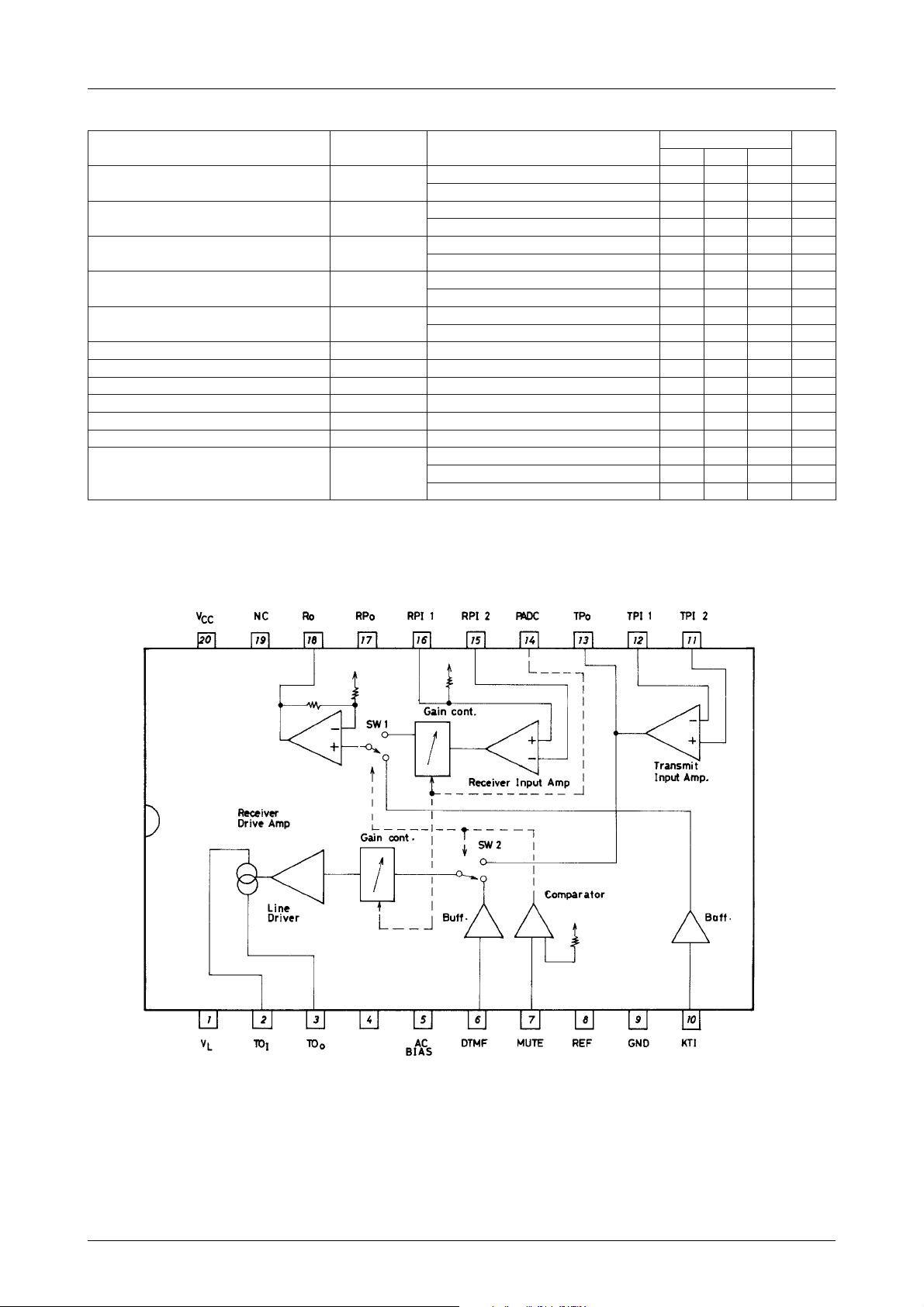
Overview
The SANYO LA8515N telephonic speech network provides
amplification, switching and line drive functions for telephone equipment. It can perform 2 to 4 line conversion and
impedance matching, and supports both DTMF and keytone
signals.
The LA8515N’s low operating current reduces line load.
Switching between the DTMF/keytone and voice circuits
is controlled directly from a single MUTE input.
The LA8515N is available in plastic 20-pin DIPs.
Features
• Direct connection to low-impedance receiver.
• DTMF/keytone and voice circuit switching controlled by
a single MUTE input.
• Receive and transmit gain are adjusted automatically in
response to the line current.
• Applicable to a wide v ariety of tr ansmitters and receivers
by selecting external components.
Specifications
Maximum Ratings at Ta = 25˚C
retemaraPlobmySsnoitidnoCsgnitaRtinU
egatloveniLV
tnerruceniLI
noitapissidrewopelbawollAxamdP 0021Wm
erutarepmetgnitarepOrpoT 57+ot03–
erutarepmetegarotSgtsT 051+ot55–
xam 51V
L
xam 051Am
L
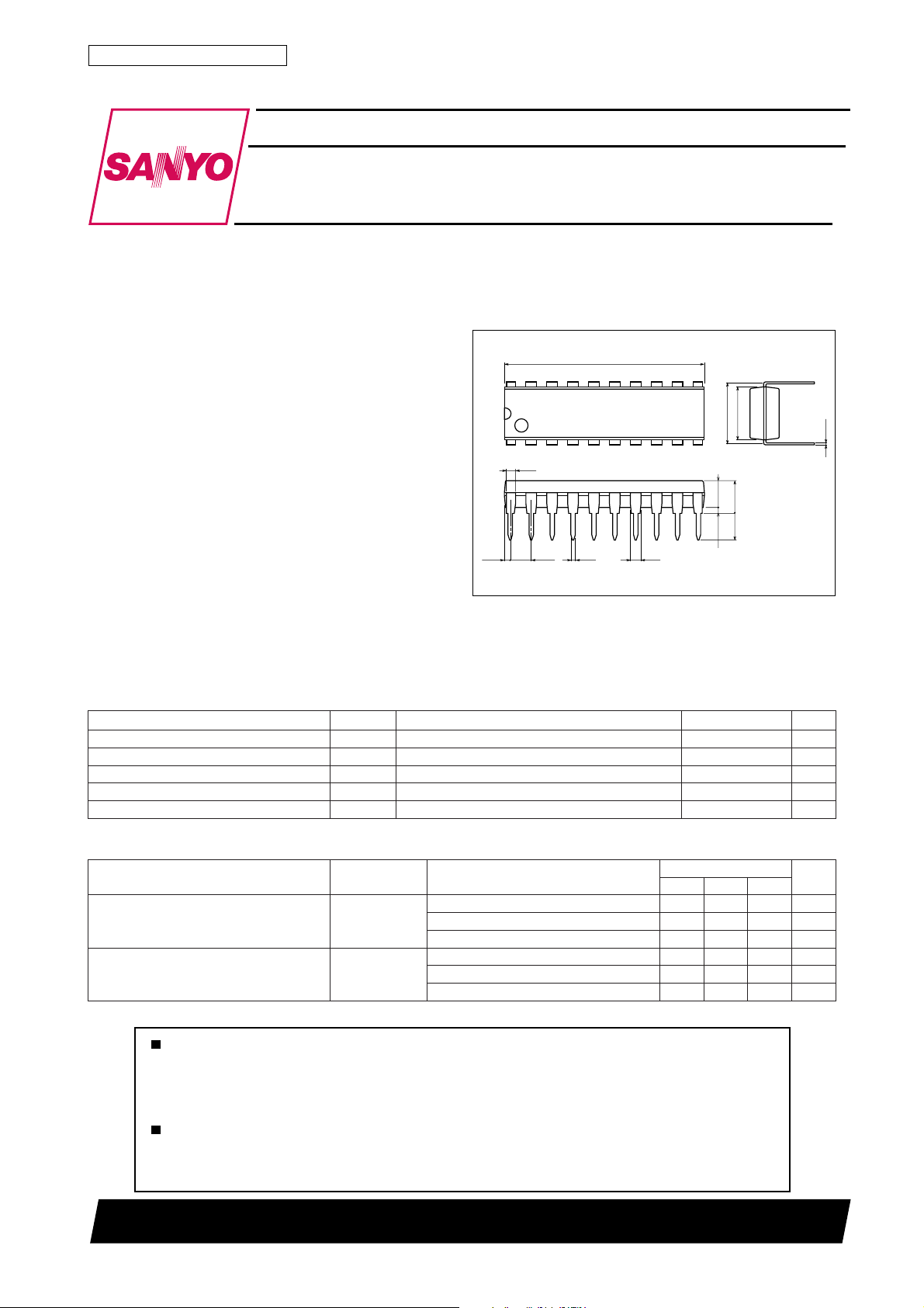
Package Dimensions
unit:mm
3021C-DIP20
[LA8515N]
24.0
20
1
1.0
(0.57)
2.54
0.5
1.2
11
7.62
10
(3.25)
0.51min
SANYO : DIP20
6.4
0.25
3.9max
3.3
˚C
˚C
Operating Characteristics at Ta = 25˚C, f=1kHz, See specified Test Circuit.
retemaraPlobmySsnoitidnoC
I
Am02=6.3V
egatloveniLV
egatlovylppuSV
L
CC
L
I
Am05=1.6V
L
I
Am021=3.21V
L
I
Am02=1.2V
L
I
Am05=6.3V
L
I
Am021=1.7V
L
12501TN (KT)/D159TA/O319TA, TS (US) No.3301–1/6
sgnitaR
nimpytxam
Continued on next page.
tinU
Page 2
Continued from preceding page.
retemaraPlobmySsnoitidnoC
niagtimsnarTG
niagevieceRG
niagFMTDG
egnarcimanydtimsnarTRD
egnarcimanydevieceRRD
ecnadepmitupniFMTDZ
ecnadepmitupniITKZ
egatlovtupnilevel-hgihETUMV
egatlovtupnilevel-wolETUMV
noitaunettatimsnarT
noitaunettaevieceR
egatlovecnerefeRV
Note) Be careful of dielectric breakdown.
∆G
∆G
T
R
FM
T
R
FMI
ITK
HI
LI
T
R
FER
LA8515N
I
L
I
L
I
L
I
L
I
L
I
L
I
L
I
L
I
L
I
L
I
L
I
L
I
L
I
L
I
L
I
L
I
L
I
L
I
L
V,Am02=
NI
V,Am021=
V,Am02=
NI
V,Am021=
V,Am02=
NI
V,Am021=
Am05=42kΩ
Am05=71kΩ
Am02=56.0V
Am05=31.1V
Am021=1.2V
sgnitaR
nimpytxam
VBd55–=830424Bd
VBd55–=5373Bd
NI
VBd02–=4–2–0Bd
VBd02–=5.9–7–5–Bd
NI
VBd03–=325272Bd
VBd03–=0222Bd
NI
%4=DHT,Am02=5.2p-pV
%4=DHT,Am021=6.4p-pV
%01=DHT,Am02=3.0p-pV
%01=DHT,Am021=5.0p-pV
Am021otAm02=5.1V
Am021otAm02=02.0V
k42aivdednuorgCDAP,Am03= Ω 3Bd
k42aivdednuorgCDAP,Am03= Ω 6Bd
CC
tinU
V
Equivalent Circuit Block Diagram
No.3301–2/6
Page 3

Test Circuit
LA8515N
Sample Application Circuit
No.3301–3/6
Page 4

LA8515N
Pin Functions
Pin Number Pin Name Description
1V
2TOITransmit output current source, input side
3TOOTransmit output current source, output side
4 Not used.
5 AC BIAS AC signal reference voltage
6 DTMF DTMF input
7 MUTE Mute control input
8 REF Reference voltage
9 GND Ground
10 KTI Key tone input
11 TPI
12 TPI
13 TP
14 PADC Pad control input
15 RPI
16 RPI
17 RP
18 R
19 NC No connection
20 V
Line voltage
L
Connected to the positive side of the line diode bridge. See the application circuit.
Connected to V
through a 27Ω resistor. Select the value of this resistor after considering the maximum expected line
L
current.
As above, but to ground through a 15Ω resistor.
This pin has a DC bias and should not be connected.
An internally-generated reference voltage.
The signal on this pin is output on V
since it is biased with the REF voltage.
Switches between the transmit side DTMF or receive side keytone, and voice circuits.
LOW : DTMF output, keytone receive output.
HiGH : Voice circuits.
Internal amplifier bias voltage. Requires an external capacitor. This voltage should not be used by external circuitry.
Connected to the negative side of the line diode bridge.
Switched through to the receive circuit output when MUTE (pin 7) is LOW. It should be decoupled using a capacitor
since it is biased with REF voltage.
Transmit input amplifier non-inverting input
2
Transmit voice circuit input. Requires a DC bias from REF (pin 8) through a resistor.
Transmit input amplifier inverting input
1
Negative feedback input. Amplifier gain and frequency response are controlled by the feedback network.
Transmit input amplifier output
O
The value of the resistor between this pin and either V
characteristics. See Electrical Characteristics.
Receive input amplifier inverting input
2
Negative feedback is applied from the amplifier output to control amplifier gain and frequency response.
Receive input amplifier inverting input
1
This pin is internally biased through a resistor using REF.
Receive input amplifier output
O
Receive circuit output
O
Connect to a low-impedance (approximately 15kΩ) receiver through a decoupling capacitor.
Supply voltage
CC
Supply voltage for internal circuitry. This supply should not be used as an external circuit supply except as the highlevel voltage for the MUTE and PADC inputs.
(pin 1) when MUTE (pin 7) is LOW. It should be decoupled using a capacitor
L
CC
or ground determines the shape of the line-current vs. gain
No.3301–4/6
Page 5

LA8515N
No.3301–5/6
Page 6

LA8515N
Specifications of any and all SANYO products described or contained herein stipulate the performance,
characteristics, and functions of the described products in the independent state, and are not guarantees
of the performance, characteristics, and functions of the described products as mounted in the customer's
products or equipment. To verify symptoms and states that cannot be evaluated in an independent device,
the customer should always evaluate and test devices mounted in the customer's products or equipment.
SANYO Electric Co., Ltd. strives to supply high-quality high-reliability products. However, any and all
semiconductor products fail with some probability. It is possible that these probabilistic failures could
give rise to accidents or events that could endanger human lives, that could give rise to smoke or fire,
or that could cause damage to other property. When designing equipment, adopt safety measures so
that these kinds of accidents or events cannot occur. Such measures include but are not limited to protective
circuits and error prevention circuits for safe design, redundant design, and structural design.
In the event that any or all SANYO products(including technical data,services) described or
contained herein are controlled under any of applicable local export control laws and regulations,
such products must not be exported without obtaining the export license from the authorities
concerned in accordance with the above law.
No part of this publication may be reproduced or transmitted in any form or by any means, electronic or
mechanical, including photocopying and recording, or any information storage or retrieval system,
or otherwise, without the prior written permission of SANYO Electric Co. , Ltd.
Any and all information described or contained herein are subject to change without notice due to
product/technology improvement, etc. When designing equipment, refer to the "Delivery Specification"
for the SANYO product that you intend to use.
Information (including circuit diagrams and circuit parameters) herein is for example only ; it is not
guaranteed for volume production. SANYO believes information herein is accurate and reliable, but
no guarantees are made or implied regarding its use or any infringements of intellectual property rights
or other rights of third parties.
This catalog provides information as of January, 2001. Specifications and information herein are subject
to change without notice.
PS No.3301–6/6
 Loading...