

Page 1
Any and all SANYO products described or contained herein do not have specifications that can handle
applications that require extremely high levels of reliability, such as life-support systems, aircraft’s
control systems, or other applications whose failure can be reasonably expected to result in serious
physical and/or material damage. Consult with your SANYO representative nearest you before using
any SANYO products described or contained herein in such applications.
SANYO assumes no responsibility for equipment failures that result from using products at values that
exceed, even momentarily, rated values (such as maximum ratings, operating condition ranges,or other
parameters) listed in products specifications of any and all SANYO products described or contained
herein.
Monolithic Linear IC
Color TV ON-Screen Display Interface
Ordering number:ENN2921A
LA7696
SANYO Electric Co.,Ltd. Semiconductor Company
TOKYO OFFICE Tokyo Bldg., 1-10, 1 Chome, Ueno, Taito-ku, TOKYO, 110-8534 JAPAN
Overview
The LA7696 is a color TV on-screen display interface IC.
The R, G, B graphic input signals can be used to provide
channel display and the fast blanking input signal can be
used to provide black-bordered character, etc. The LA7696
also contains an auto green function to make green color
more vivid and a service switch function in a DIP-20 slimtype package.
Input signals are R-Y, G-Y, B-Y, and -Y and output signals
are converted to R, G, B primary color signals.
Functions and Features
• The R, G, B graphic input signals can be used to provide
on-screen display.
The R, G, B graphic input signals can be combined to
select six colors in addition to white and black.
• Fast blanking function.
• The black level and white level can be set separately, as
desired, in the graphic mode.
• Output of primary color drive type (input : R-Y, G-Y, BY, -Y).
• Excellent frequency characteristic allowing the LA7696
to be used in a high-resolution TV.
• Auto green function.
Bluish green turns more vivid green.
• Service switch function.
It is easy to control the screen grid.
• The LA7696 can be easily used in conjunction with the
LA7650, 7680 (under development) series.
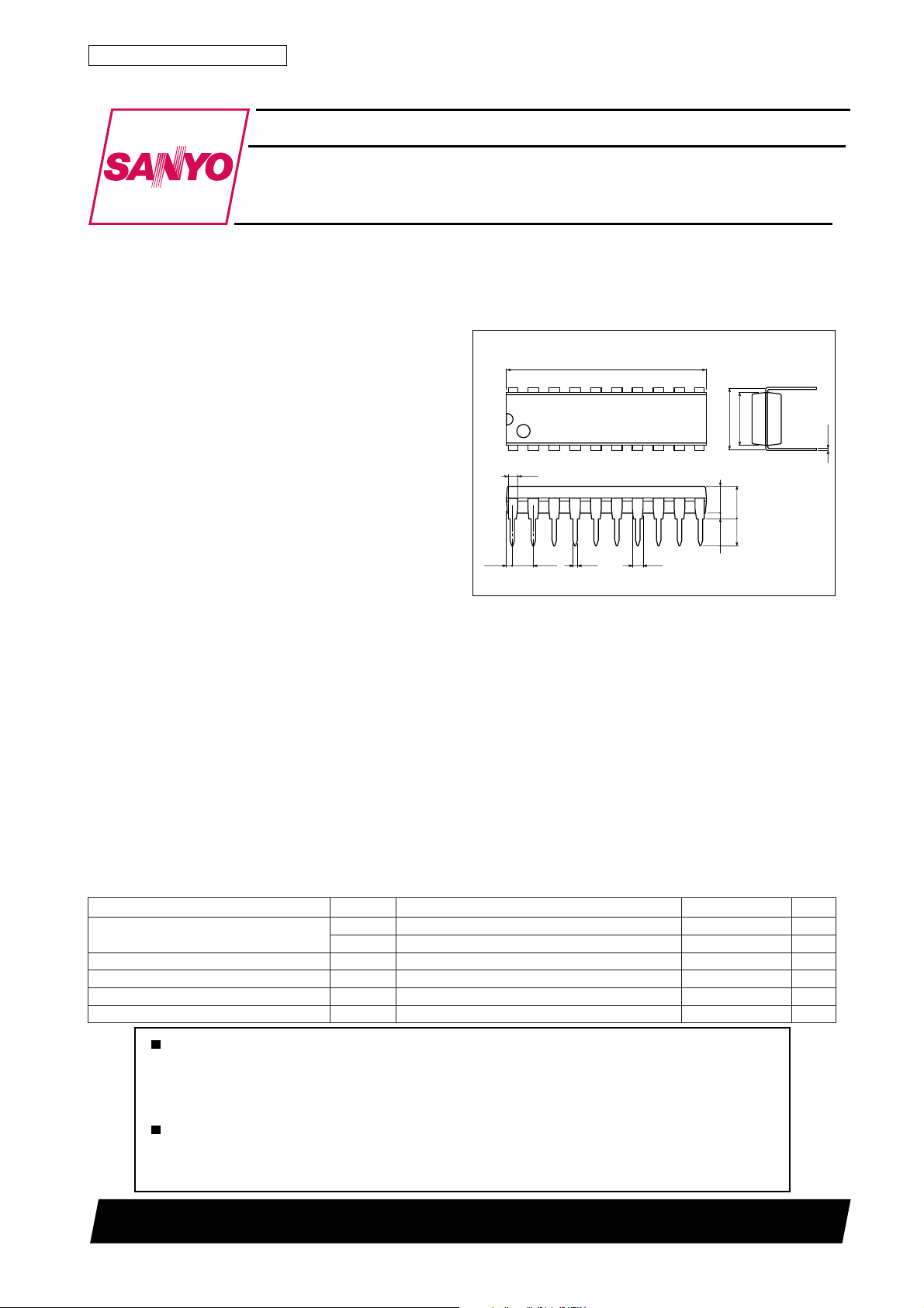
Package Dimensions
unit:mm
3021C-DIP20
[LA7696]
24.0
20
1
1.0
(0.57)
2.54
0.5
1.2
11
7.62
10
(3.25)
3.9max
3.3
0.51min
SANYO : DIP20
6.4
0.25
Specifications
Maximum Ratings at Ta = 25˚C
retemaraPlobmySsnoitidnoCsgnitaRtinU
egatlovylppusmumixaM
tnerructuo-wolfCII
noitapissidrewopelbawollAxamdP 077Wm
erutarepmetgnitarepOrpoT 56+ot01–
erutarepmetegarotSgtsT 521+ot55–
V02xam 41V
VOxam91,71,51sniP 41V
xam81,61,41sniP 02Am
O
Ta≤65˚C
O2500TN (KT)/41095TH (KOTO)/N228YT, TS No.2921–1/6
˚C
˚C
Page 2

LA7696
Operating Conditions at Ta = 25˚C
retemaraPlobmySsnoitidnoCsgnitaRtinU
egatlovylppusdednemmoceRV
egnaregatlovgnitarepOV
02
po 31ot01V
02
Operating Characteristics at Ta = 25˚C, VCC=V20=12V *C=R, G, B
retemaraPlobmySsnoitidnoC
egatlovnwodkaerbtuptuOVB
tnerrucylppuSI
egatlovCDtuptuOV
egatlovlaitnereffidCDtuptuO
tnerrucecivreS
levelkcalbscihparGV
leveletihwscihparGV
niaGGzHk1=f,p-pV1,cdV5.3=Y-,cdV2.5=Y-C09.059.000.1
scitsiretcarahcycneuqerFBd3-fp-pV1,cdV5.3=Y-,cdV2.5=Y-C0.80.41zHM
edomFFOtaegatlovtuptuOV
rotcafnoitrotsidY-Y-
rotcafnoitrotsidY-CY-C
htdiweslupBF&GCP
emityaledBF&GCdT
htdiweslupBFWP
rorrehtdiweslupBF
emityaledBFdT
htdiweslupGCWP
rorrehtdiweslupGC
emityaledGCdT
neerg-otuaumixaMxamGA
neerg-otuaelddiMdimGA
egatlovlevel-HtupnIV
egatlovlevel-LtupnIV
V
CC
egatlovCDtuptuofoecnedneped
∆V
I
I
∆ WP
∆ WP
∆ tuoV
I
OEC
C
02725344Am
CC
CE
CE
V
TCAFC
dleiFC
V
CLB
V
CLW
B,G,R
tsiD
tsiD
BFGCW
BFGC
BF
BF
BF
GC
V
GC
V
GC
V
V210= → V21
V210= → V8
HI
LI
I,Am1.0=
V(0=
B
V0.5= 1.0Am
31
LB
LW
cdV2.5=Y
cdV2.5=Y
cdV2.5=Y
cdV2.5=Y
cdV2.5=Y
cdV8.3=
LB
cdV8.3=
LB
cdV8.3=
LB
)V0.5=61V
31
nepo:31nipcdV2.5=Y-C,cdV0.4=Y-5.40.55.5V
Votpudellup:31niP
CC
cdV0.5=Y-,cdV2.5=Y-C4.45.46.4V
k2.2htiw Ω 5.27.29.2Am
V5=BF,V0=GC,cdV3.4=5.40.55.5V
V5=BF=GC,cdV4.5=5.50.65.6V
cdV2.5=Y-C,zHk1,p-pV1,cdV5.3=Y- 1%
cdV5.3=Y-,zHk1,p-pV1,cdV2.5=Y-C 1%
V,cdV5.4=Y–,sn052,o-pV5=GC=BF
LW
V,cdV5.4=Y–,sn052,o-pV5=GC=BF
LW
V,cdV5.2=Y-,sn052,o-pV5=BF
LB
V,cdV5.2=Y-,sn052,o-pV5=BF
LB
V,cdV5.2=Y-,sn052,o-pV5=BF
LB
V,sn052,o-pV5=GC,cdV5=BF
LW
V,sn052,o-pV5=GC,cdV5=BF
LW
V,sn052,o-pV5=GC,cdV5=BF
LW
V,cdV0.4=Y-,cdV2.5=Y-C
LB
V,cdV0.4=Y-,cdV2.5=Y-C
LB
V(cdV2.5=Y-C,cdV0.4=Y-
)V21=4.44.94.41V/%
CC
-C,cdV3.4=
-C,cdV3.4=
-C,cdV3.4=
,cdV9.5=
,cdV9.5=
,cdV9.5=
,cdV0.2=Y-,cdV2.6=Y-G,cdV2.5=Y-B=Y-R
,cdV0.2=Y-,cdV2.6=Y-G,cdV2.5=Y-B=Y-R
V,V4.5=
V9.5=3.2V
LW
V,V4.5=
V9.5=8.0V
LW
nimpytxam
2.0–02.0+V
-C,cdV9.5=
502552503sn
-C,cdV9.5=
512562513sn
52–052+sn
512562513sn
52–052+sn
9.13.27.2V
9.01.13.1V
Note ) Be sure to connect a protection resistor to pins 15, 17, 19 to prevent the IC from breaking down when discharge
occurs in the cathode-ray tude.
21V
sgnitaR
86001sn
75001sn
56001sn
tinU
No.2921–2/6
Page 3

Block Diagram
LA7696
Auto Green Function
Basic Operation
When a standard NTSC demodulator is used to demodulate green color, an original green color turns bluish green. The
auto green function works to reduce the B-Y component for green color correction so that the original green color can
be reproduced faithfully. This corrention can be provided in the range shown in Fig. 1.
Fig. 1. Auto Green Correction Range
The auto green function compares each color difference signal of R-Y, G-Y, B-Y and if the G-Y component is larger
than the R-Y, B-Y components the B-Y component is reduced in proportion to the difference between them.
The auto green function is also capable of providing your desired correction by setting the control voltage on pin 12.
When the control voltage on pin 12 is changed as 0V → 12V, the input signals are changed equivalently as shown in
Example 1. Actually, 5.2V offset given to R-Y, G-Y, B-Y with -Y=4V causes the B output (pin 14 of LA7696) to
change as 4.83V → 4.64V.
No.2921–3/6
Page 4

LA7696
Example 1
Control voltage on pin 12
0V 12V
R-Y=–0.212V Changed R-Y=–0.212V
G-Y=+0.100V equivalently G-Y=+0.100V
B-Y=–0.167V min B-Y=–0.358V max
If the G-Y component is +0.1V when a color on the G-Y demodulation axis comes, the B output voltage changes with the
control voltage on pin 12 as shown in Fig. 2. The maximum change is –0.19V.
Fig. 2. Auto Green Characteristic
Function of the Service Switch
(screen grid voltage adjustment function during white balance adjustment)
The LA7679 output can be switched between the three modes a , b and c described below by the state of pin 13.
a) Service switch function (for adjustment by a serviceman in the field)
This function is provided to allow the screen grid voltage to be adjusted easily during white balance adjustment.
As shown in Figure 3, when pin 13 is connected to VCC through the resistor R13, the pin 15, 17 and 19 output transistors
will be off. At the same time, a current equi v alent to the cur rent (I13) flo wing in resistor R13 flows into each of the pins
15, 17 and 19. As a result, the CRT cathode potential can be fixed at an arbitrary value by changing R13. Thus the screen
grid voltage can be adjusted easily.
The current flowing into pins 15, 17 and 19 is determined by the following formula.
V
I15=I17=I19=I13=
CC
2×R13
Since pin 13 is connected to VCC through a 2.2kΩ resistor, a current of about 2.7mA flo ws into each pin 15, 17 and 19.
If + High B is set to 200V, the CRT cathode is fixed at 160V. The purpose of Tr1 is to protect the IC.
b) Service switch function (for adjustment at the factory)
The pin 15, 17 and 19 currents can be set to 0 (I15=I17=I19=0) by applying 5V (when VCC=12V) to pin 13. In this state
the pin 15, 17 and 19 output transistors will be off. Fix the CRT cathode potential by connecting a constant current
cource to the points (a total of 3 points) indicated with stars in Figure 3, and then adjust the screen grid voltage.
The mode is appropriate for use in the manufacturing process where the TV set is assembled.
C)Normal operation
When pin 13 is left open, the video signal will be output from pins 15, 17 and 19.
No.2921–4/6
Page 5

LA7696
LA7696 Sample Application Circuit
Fig. 3. Function of the servide switch
No.2921–5/6
Page 6

LA7696
Specifications of any and all SANYO products described or contained herein stipulate the performance,
characteristics, and functions of the described products in the independent state, and are not guarantees
of the performance, characteristics, and functions of the described products as mounted in the customer's
products or equipment. To verify symptoms and states that cannot be evaluated in an independent device,
the customer should always evaluate and test devices mounted in the customer's products or equipment.
SANYO Electric Co., Ltd. strives to supply high-quality high-reliability products. However, any and all
semiconductor products fail with some probability. It is possible that these probabilistic failures could
give rise to accidents or events that could endanger human lives, that could give rise to smoke or fire,
or that could cause damage to other property. When designing equipment, adopt safety measures so
that these kinds of accidents or events cannot occur. Such measures include but are not limited to protective
circuits and error prevention circuits for safe design, redundant design, and structural design.
In the event that any or all SANYO products(including technical data,services) described or
contained herein are controlled under any of applicable local export control laws and regulations,
such products must not be exported without obtaining the export license from the authorities
concerned in accordance with the above law.
No part of this publication may be reproduced or transmitted in any form or by any means, electronic or
mechanical, including photocopying and recording, or any information storage or retrieval system,
or otherwise, without the prior written permission of SANYO Electric Co. , Ltd.
Any and all information described or contained herein are subject to change without notice due to
product/technology improvement, etc. When designing equipment, refer to the "Delivery Specification"
for the SANYO product that you intend to use.
Information (including circuit diagrams and circuit parameters) herein is for example only ; it is not
guaranteed for volume production. SANYO believes information herein is accurate and reliable, but
no guarantees are made or implied regarding its use or any infringements of intellectual property rights
or other rights of third parties.
This catalog provides information as of October, 2000. Specifications and information herein are subject
to change without notice.
PS No.2921–6/6
 Loading...