

SANYO LA7626, LA7625 Datasheet
Ordering number: EN 2289B
Monolithic Linear IC
LA7625, 7626
Video, Chroma and Deflection Circuit for
Color Television Sets
Overview
The LA7625 and LA7626 are based on the LA7620 and
LA7621 with the video circuit DC restoration factor changed
to 100%. The LA7625 and LA7626 are small, multifunction
ICs in which video, chroma and deflection circuits for NTSC
color TV system are packaged in a shrink-type DIP30S (the
same type as the earlier DIP22). In addition to being small,
these ICs greatly reduce the number of components required
and reduce the number of adjustments that must be made. By
combining the LA7625 or LA7626 with the LA7555 or
LA7577 VIF/SIF IC, or LA7832, LA7833, LA7837, or
LA7838 vertical output IC, it is possible to process all
functions of the color television signal system. Note that the
LA7625 has a peak clipping circuit built into the video circuit,
and is suited primarily for compact sets, while the LA7626
does not have a peak clipping circuit and is suited for larger
sets.
Features
.
Small package
.
Few peripheral components needed.
.
Few adjustments needed.
(The functions listed below require no adjustments.)
.
Chroma VCO (APC)
.
Horizontal oscillation H-Hold
.
Vertical oscillation V-Hold
.
Multifunctional.
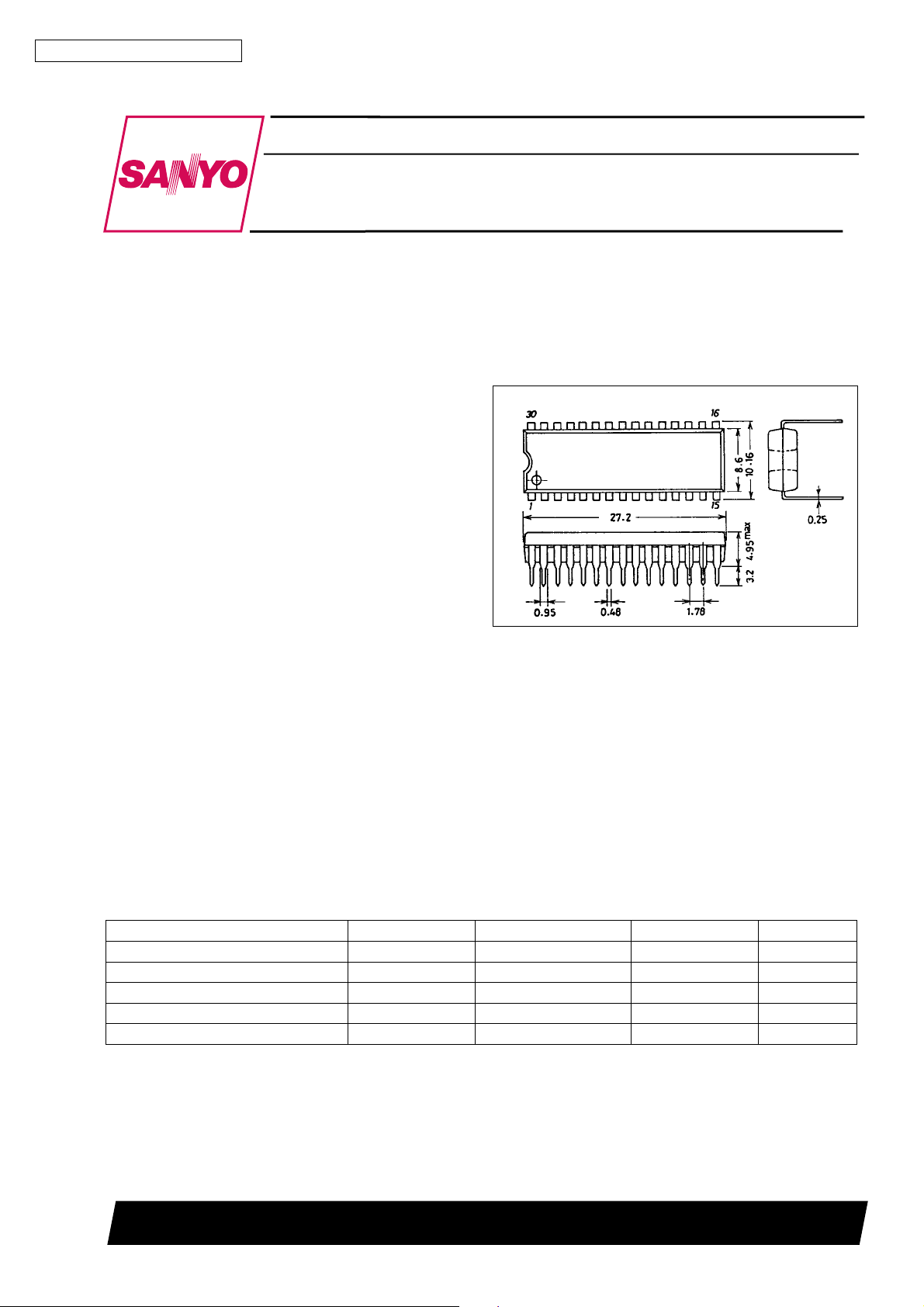
Package Dimensions
unit : mm
3061-DIP30S
[LA7625,7626]
SANYO : DIP30S
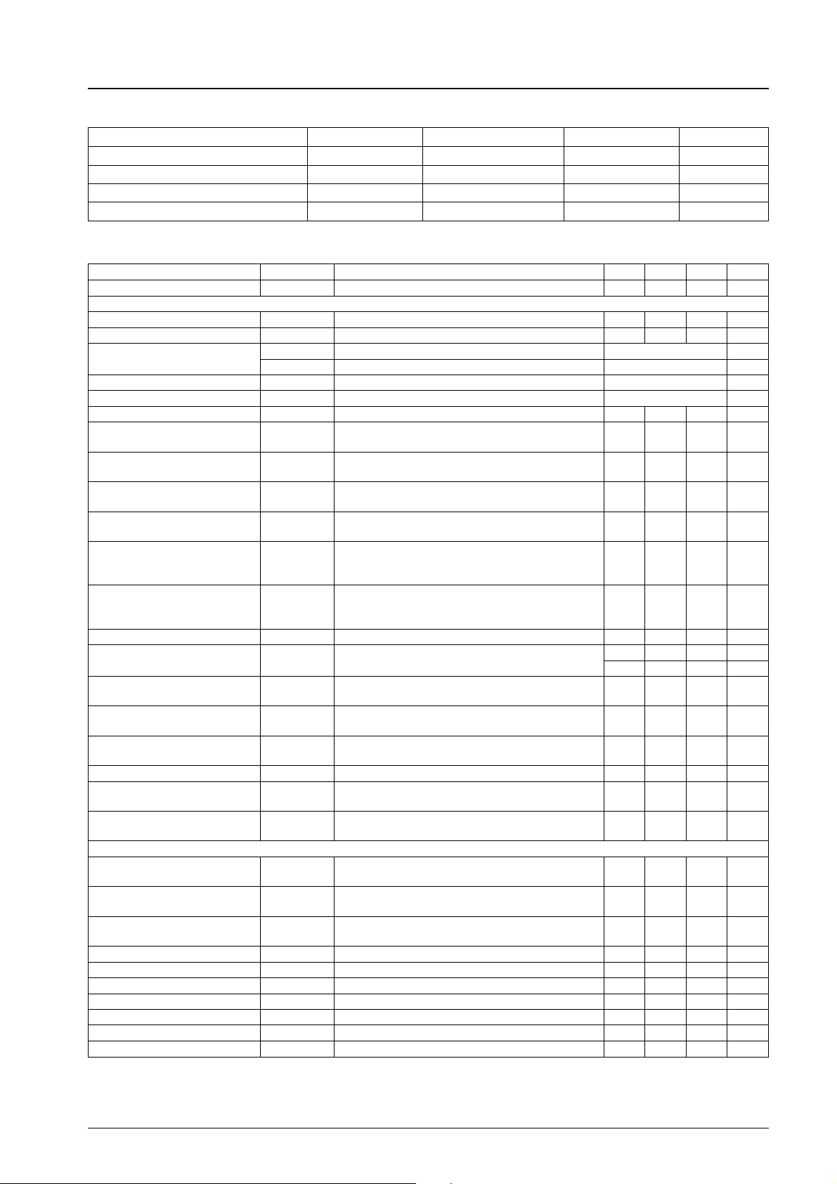
Specifications
Maximum Ratings atTa=25°C
Parameter Symbol Conditions Ratings Unit
Maximum supply voltage V
Maximum supply current I
Allowable power dissipation Pd max Ta % 65°C 1100 mW
Operating temperature Topr –20 to +85
Storage temperature Tstg –55 to +125
max 14.0 V
16
max 15.0 mA
22
SANYO Electric Co.,Ltd. Semiconductor Bussiness Headquarters
TOKYO OFFICE Tokyo Bldg., 1-10, 1 Chome, Ueno, Taito-ku, TOKYO, 110 JAPAN
62095HA (II) No.2289 - 1/6
C
°
C
°
LA7625, 7626
Operating Conditions atTa=25°C
Parameter Symbol Conditions Ratings Unit
Recommended supply voltage V
Recommended supply current I
Operating supply voltage range V
Operating supply current range I
Electrical Characteristics atTa=25°C, VCC=V16=12V,ICC=I22=10mA
16
22
op 9.0 to 14.0 V
16
op 8.5 to 15.0 mA
22
12.0 V
10.0 mA
Parameter Symbol
Circuit current I
16
No signal 40 53 75 mA
Conditions
min typ max Unit
[Deflection block]
Horizontal supply voltage V
Sync separation input DC level V
Vertical free-running
frequency 1
Z22
S.S
f
1f
V
f
2f
V
Vertical blanking pulse width PW V.blk 19.25/f
Vertical output pulse width PW V.out 10.25/f
Vertical drive stage voltage gain G
Vertical output pulse start
voltage
Vertical pull-in operation start
voltage
Vertical blanking pulse wave
peak value
Horizontal free-running
frequency
V
Vcds 4.0 V
Vvps 4.0 V
VV.blk 10 V
f
H
Frequency deviation versus 15.734 kHz –70 0 130 Hz
8.2 8.7 9.2 V
9.0 9.3 9.6 V
/296.5 Hz
H
/224.5 Hz
H
H
H
s
s
13 16.2 19 dB
Dependence of horizontal
oscillation frequency on
supply voltage
∆ f
(V) fH(8V)–fH(7V) –10 0 10 Hz
H
Dependence of horizontal
oscillation frequency on
operating temperature
∆ f
/∆ TTa= –10°Cto60°C –1.5 1.5 Hz/deg
H
Horizontal output pulse width PW Hout 23.5 24.5 25.5 µs
Horizontal sync pull-in
frequency range
Horizontal output pulse start
voltage
Horizontal free-running
frequency drift with time
Hotizontal blanking
threshold level
Horizontal output drive current I
Horizontal oscillation control
sensitivity
Hold-down operation start
voltage
f
pull Differential versus 15.734 kHz
H
V
pos 5.5 V
H
∆ f
V
.blk 11 V
H
H.O
B
fH
V
HD
for 5 seconds to 30 minutes after power is applied –50 –10 30 Hz
HT
Reference value only (i.e. not specified) 236 Hz/µA
400 Hz
–500 Hz
2.0 4.5 mA
0.55 0.65 0.75 V
[Video block]
Video tone
control characteristics 1
Video tone
control characteristics 1
RE1
RE2
Video voltage gain AV
f = 2 MHz,
Video tone VR: 0 V
f = 2 MHz,
Video tone VR: 12 V
f = 100 kHz,
Video tone VR: 5.5 V
–5 –3 –1 dB
12 15 18 dB
12 15 18 dB
Contrast control center eo f = 100 kHz, input: 100 mVp-p 0.2 0.3 0.4 Vp-p
Contrast variable range ∆ eo f = 100 kHz 16 18 20 dB
Bright control characteristics 1 BR1 No signal, bright VR: 3 V 8 V
Bright control characteristics 2 BR2 No signal, bright VR: 6 V 5.8 6.3 6.8 V
Bright control characteristics 3 BR3 No signal, bright VR: 9 V 4.5 V
Frequency response f f = 5 MHz/f = 100 kHz –5 dB
DC restoration factor R
DC
STAIR STEP signal reference value 100 %
Continued on next page.
No.2289 - 2/6
 Loading...