

Page 1
Ordering number:ENN5119
Monolithic Linear IC
LA7449, 7449M
Video Signal Processing IC
for VHS VCR Systems
Overview
The LA7449 and 7449M are video signal processing singlechip ICs that handle the PAL-G, B and I, 4.43 NTSC,
MESECAM and NAP-G, B and I formats. IC internal trimming is used to make the LA7449, 7449M completely adjustment free, and in combination with a special-purpose
CCD (thd LC89970, 89970M) they provide a significant
reduction in external components, including the glass delay line. Thus the LA7449, 7449M can significantly reduce the signal processing board manufacturing costs. Furthermore, the LA7449, 7449M support the NAP format
(NTSC to PAL conv ersion) that is becoming widespread in
Europe, China and other markets.
Features
• Completely adjustment free.
The AGC, carrier, deviation, and PB-Y level are adjustment free.
The YC record current can also be made adjustment free
by using the LA7411, 7416 as the head amplifier.
• Support for NAP and PAL color array correction.
Full modulation using a balanced modulator allows playback and conversion to PAL format of NTSC signals recorded on tape.
• Crosstalk exclusion in combination with a special-purpose CCD
Crosstalk can be excluded without using a glass delay
line by combining the LA7449, 7449M with a specialpurpose CCD (the LC89970, 89970M).
• Minimal number of external components.
New built-in components :
– Detail enhancer CR.
– C-trap in the Y low-pass filter.
– Playback C low-pass filter.
• High performance and multiple functions.
Linear phase picture controller.
Double high-pass noise canceller, high-speed AFC, DCC.
New built-in functions.
– NAP circuit.
– AVNS (advanced vertical noise suppressor).
– Automatic QH insertion.
– FM AGC.
• Miniature package (48-pin QIP or DIP).
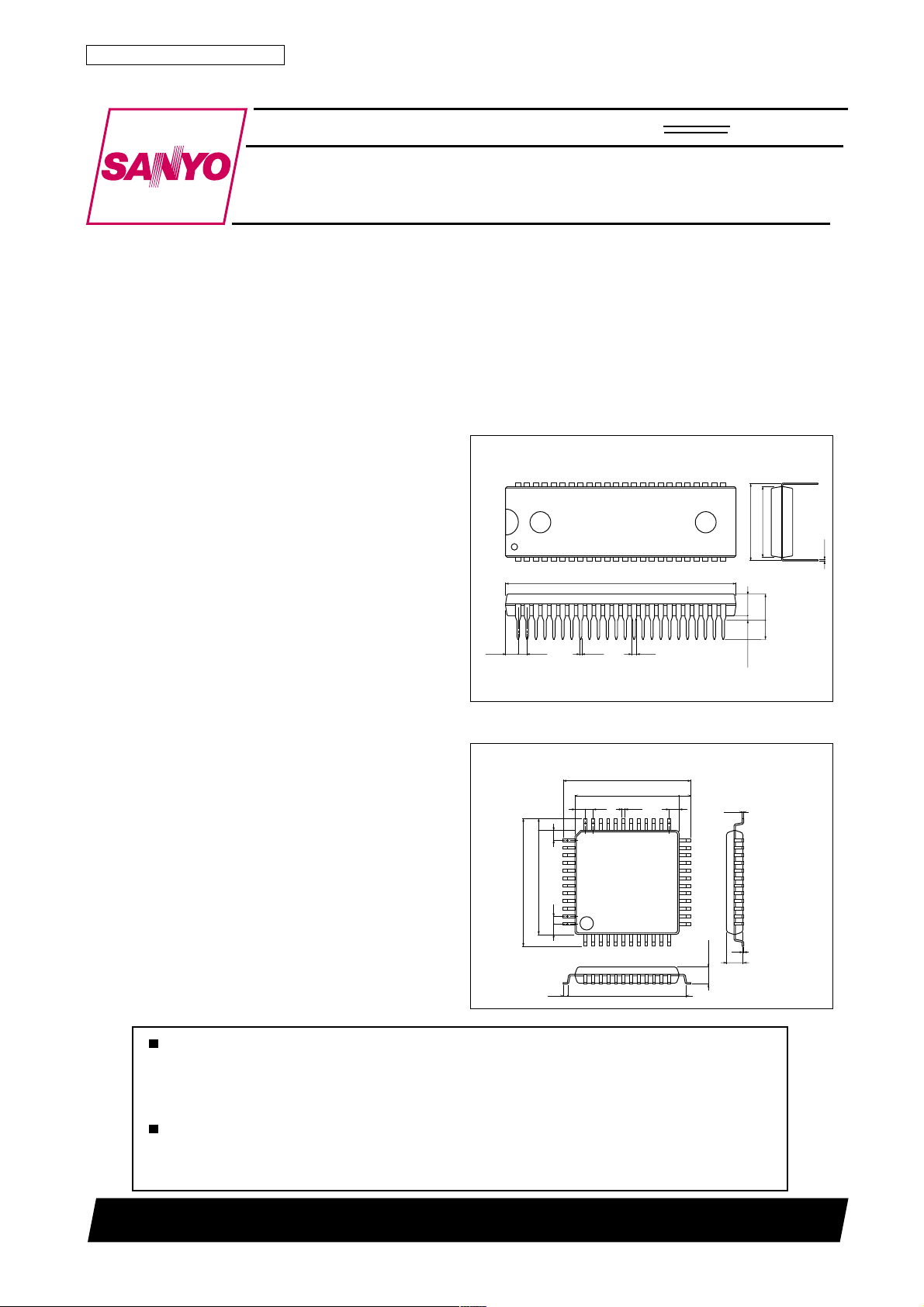
Package Dimensions
unit:mm
3149-DIP48S
[LA7449]
48
1
1.78
2.53
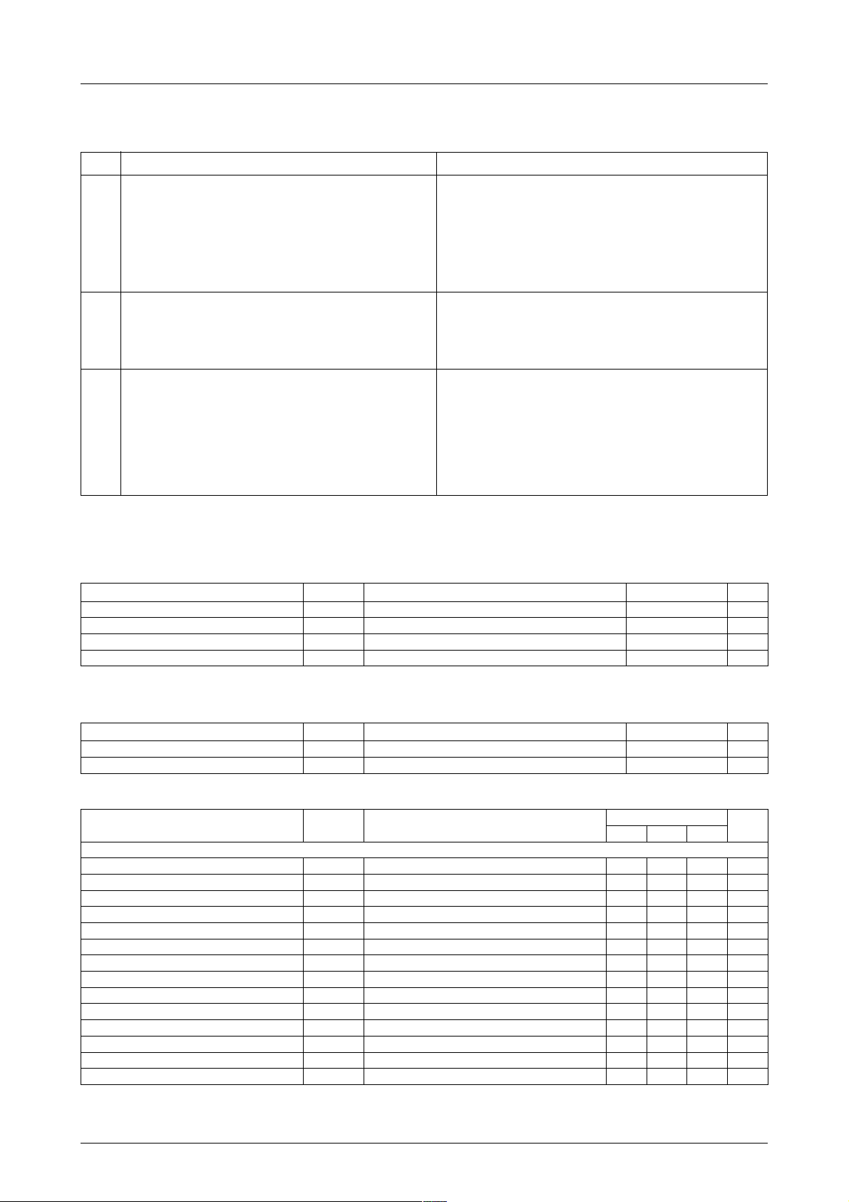
unit:mm
3156-QIP48E
1.6
14.0
17.2
0.8
46.0
[LA7449M]
17.2
14.0
1.0
15.6
0.35
1.05
1.5
25
12
0.48
1.5
36
37
1.5
1.0
48
1.5
1
25
24
1.6
24
13
3.0max
SANYO : QIP48E
SANYO : DIP48S
0.15
0.1
2.7
15.24
4.25
0.51min
13.8
0.25
5.1max
3.8
Any and all SANYO products described or contained herein do not have specifications that can handle
applications that require extremely high levels of reliability, such as life-support systems, aircraft’s
control systems, or other applications whose failure can be reasonably expected to result in serious
physical and/or material damage. Consult with your SANYO representative nearest you before using
any SANYO products described or contained herein in such applications.
SANYO assumes no responsibility for equipment failures that result from using products at values that
exceed, even momentarily, rated values (such as maximum ratings, operating condition ranges,or other
parameters) listed in products specifications of any and all SANYO products described or contained
herein.
SANYO Electric Co.,Ltd. Semiconductor Company
TOKYO OFFICE Tokyo Bldg., 1-10, 1 Chome, Ueno, Taito-ku, TOKYO, 110-8534 JAPAN
O2500TN (KT)/62095HA (OT) No.5119–1/10
Page 2
LA7449, 7449M
Functions
All VHS format VCR signal processing functions.
Luminance Chrominance
Video amplifier. 4.43 BPF Half H killer
Feedback clamp ACC amplifier. BGP generator
R/P YNR (AVNS) Main converter VCO
REC Pre LPF White/dark clip Killer
PB Sub LPF NAP DPLL
Main LPF ACC det. Killer det.
VCA 1.3M LPF Phase shifter
Sync separator VXO/XO Sub converter
4.2V regulator Side lock det. 5.06 BPF
3rd lock protector
Video AGC amplifier. NL emphasis Preamplifier. Burst gate amplifier.
Video AGC det. Main emphasis Burst emphasis (NTSC)
Detail enhancer FM modulator APC det.
1/2 fH carrier shift AFC det.
FM AGC amplifier. Drop out det. Pre amplifier. APC det.
FM AGC det. NL de-emphasis Burst de-emhasis (NTSC) ID det.
Double limiter Picture control PB amplifier DCC
FM demodulator Y/C mix Killer Trick det.
Double highpass noise canceller PAL burst sequence
QV/QH/character insert –Compensator
Main de-emphasis Carrier balancer
DOC Burst gate amplifier.
Specifications
Pin numbers are for the LA7449M
Maximum Ratings at Ta = 25˚C
retemaraPlobmySsnoitidnoCsgnitaRtinU
egatlovylppusmumuxaMV
noitapissidrewopelbawollAxamdP *0531Wm
erutarepmetgnitarepOrpoT 56+ot01–
erutarepmetegarotSgtsT 051+ot04–
Note : * When mounted on a 70mm by 65mm, 1.5mm thickness Bakelite board. The value for the DIP package is 1150mW.
Operating Conditions at Ta = 25˚C
retemaraPlobmySsnoitidnoCsgnitaRtinU
egatlovylppusdednemmoceRV
egatlovylppusgnitarepOV
Operating Characteristics at Ta = 25˚C, V
retemaraPlobmySsnoitidnoC
]metsysYedomdroceR[
niardtnerrucedomdroceRI
1leveltuptuoEEV
1scitsiretcarahcCGA1CGAlangisoedivp-pV0.2metsyszH05:tupnI50.251.252.2p-pV
2scitsiretcarahcCGA2CGAlangisoedivp-pV5.0metsyszH05:tupnI09.100.201.2p-pV
3scitsiretcarahcCGA3CGABd6desaercniCNYSylnohtliwmetsyszH05:tupnI555516596p-pVm
4scitsiretcarahcCGA4CGABd6desaercedCNYSylnohtliwmetsyszH05:tupnI073014054p-pVm
leveltuptuorotarapescnySV
htdiwesluptuptuorotarapescnySWP
emityaleddrocererptuptuorotarapescnyS
leveldlohserhtrotarapescnySHT
levelnoitresniH-oduesP
levelnoitresnietihW
egatlovnoitcetedACVV
PL/PEnoitarepoRNYdroceRV
xam 0.7V
CC
Ta≤65˚C *
CC
po 2.5ot8.4V
CC
=5.0V
CC
nimpytxam
RCC
1langisoedivp-pV0.1metsyszH05:tupnI59.150.251.2p-pV
EE
RYS
RYS
∆T
RYS
RYS
∆ DH
R
∆ HW
R
ACV
1RNY-R
langisoedivp-pV0.1:tupnI001031061Am
thgiehevawesluptuptuoTUO-CNYSehT9.31.43.4V
htdiwesluptuptuoTUO-CNYSehT0.43.46.4sµ
emityaledTUO-CNYSehT9.01.13.1sµ
A41TotdeilppaV7.2htiW004– 003– 002– Vm
A41TotdeilppaV3.1htiW001052004Vm
00.302.304.3V
langisrabrolocdradnatsmetsyszH05:tupnI012141p-pVm
˚C
˚C
0.5V
sgnitaR
02– 51– Bd
tinU
Continued on next page.
No.5119–2/10
Page 3
Continued from preceding page.
retemaraPlobmySsnoitidnoC
]metsysYedomdroceR[
leveltuptuorotaludomMFV
1ycneuqerfreirraCF
1noitaiveD1VEDmetsyszH0559.000.150.1zHM
ytiraenilrotaludomMFL
f2/1
H
level
tfihsreirracSC5.68.71.9zHk
niagsisahpmEG
1scitsiretcarahcsisahpmeLNG
2scitsiretcarahcsisahpmeLNG
3scitsiretcarahcsisahpmeLNG
1scitsiretcarahcsisapmeniaMG
2scitsiretcarahcsisapmeniaMG
levelgnilppilcetihWLCWlangisoediv%001etihw,p-pV0.1:tupnI681591402%
levelgnippilckraDLCDlangisoediv%001etihw,p-pV0.1:tupnI55– 05– 54– %
]metsysYedomkcabyalP[
niardtnerrucedomkcabyalPI
emitnoitasnepmoctuoporDT
niagpoolCODG
levelYkcabyalPV
ytiraenilrotaludomedMFL
ytivitisnesnoitaludomeDS
egakaelreirraCLCp-pVm006,zHM4:tupnI04– 53– Bd
]metsysYedomdroceR[
leveltuptuorotarapescnySV
egatlovrotalugerV2.4V
1levelrotallicsoOXVV
1scitsiretcarahcCCAdroceRCCA
2scitsiretcarahcCCAdroceRCCA
leveltupninorellikCCA
leveltuptuonorellikCCA
leveltupniyrevocerrellikCCA
ytivitisneslortnocOXVS
LA7449, 7449M
sgnitaR
nimpytxam
1scitsiretcarahcycneuqerfFPL-Y1FPLYzHk005ottcepserhtiwnoitaunettazHM1ehT5.0– 0.05.0+Bd
2scitsiretcarahcycneuqerfFPL-Y2FPLYzHk005ottcepserhtiwnoitaunettazHM2ehT0.1– 0.00.1+Bd
3scitsiretcarahcycneuqerfFPL-Y3FPLYzHk005ottcepserhtiwnoitaunettazHM3ehT5.2– 5.0– 0.1+Bd
4scitsiretcarahcycneuqerfFPL-Y4FPLYzHk005ottcepserhtiwnoitaunettazHM34.4ehT 52– Bd
MF
noitrotsidcinomrahdn2tuptuorotaludomMFH
1scitsiretcarahcrecnahneliateDG
2scitsiretcarahcrecnahneliateDG
3scitsiretcarahcrecnahneliateDG
PE/PLscitsiretcarahcRNYkcabyalPG
1scitsiretcarahcsisahpme-edLNG
2scitsiretcarahcsisahpme-edLNG
1scitsiretcarahcrellecnacesionelbuoDG
2scitsiretcarahcrellecnacesionelbuoDG
3scitsiretcarahcrellecnacesionelbuoDG
1scitsiretcarahcesnopserdrahLTC-CIPG
2scitsiretcarahcesnopserdrahLTC-CIPG
1scitsiretcarahcesnopsertfosLTC-CIPG
2scitsiretcarahcesnopsertfosLTC-CIPG
)kcabyalp(levelnoitresniV-oduesP
)kcabyalp(levelnoitresniH-oduesP
)kcabyalp(levelnoitresnietihW
htdiwesluptuptuorotarapescnySWP
emityaleddrocer-erptuptuorotarapescnyS
]metsysecnanimorhcedomdroceR[
tsrubtuptuonoisrevnocdnabwolecnanimorhC
1MF
DOM
DOM
PME
1TED
2TED
3TED
1PMELN
2PMELN
3PMELN
1EM
2EM
PCC
COD
COD
TUOV
MED
MED
1RNY-P
1EDLN
2EDLN
1CNW
2CNW
3CNW
1HP
2HP
1SP
2SP
∆ DV
P
∆ DH
P
∆ HW
P
PYS
PYS
∆T
PYS
GER
V
83-RO
1R-OXV
1R-
2R-
V
V
NO-KCCA
V
KCCA-O
FFO-KCCA
OXV
tupnioN0.12.14.1p-pV
metsyszH057.38.39.3zHM
04– 53– Bd
2– 02+%
evaweniszHk01,p-pV5.0tupnI5.0– 0.05.0+Bd
evaweniszHM2,p-pVm613:tupnI6.19.16.2Bd
evaweniszHM2,p-pVm001:tupnI1.31.41.5Bd
evaweniszHM2,p-pVm6.13:tupnI3.53.63.7Bd
evaweniszHM2,p-pVm005:tupnI5.04.13.2Bd
evaweniszHM2,p-pVm851:tupnI6.28.32.5Bd
evaweniszHM2,p-pVm05:tupnI9.44.69.7Bd
evaweniszHk005,p-pVm001:tupnI9.42.55.5Bd
evaweniszHM2,p-pVm001:tupnI1.316.311.41Bd
531061581Am
27.058.059.0sm
retalH50.1– 0.00.1+Bd
noitaived
zHM6,4,25.3– 0.05.3+%
WC+etihw%05:tupnI5.2– Bd
evaweniszHM2,p-pVm05:tupnI5.01– 0.9– 5.7– Bd
evaweniszHM2,p-pVm851tupnI8.1– 3.1– 8.0– Bd
evaweniszHM2,p-pVm05tupnI2.6– 2.5– 2.4– Bd
evaweniszHM2,p-pVm8.51tupnI7.11– 7.01– 7.8– Bd
A41TotdeilppaV5htiW051– 05– 05+Vm
A41TotdeilppaV7.2htiW004– 003– 002– Vm
A41TotdeilppaV3.1htiW001052004Vm
Bd6
Bd6
zHM0.1ahtiwlangisMFnafokcabyalproF
evaweniszHM2,p-pVm851:tupnI0.6– 0.5– 0.4– Bd
p-pVm851,zHM1=fevawenis+oediv%05:tupnI5.45.55.6Bd
p-pVm851,zHM2=fevawenis+oediv%05:tupnI0.80.90.01Bd
p-pVm851,zHM1=fevawenis+oediv%05:tupnI5.4– 5.3– 5.2– Bd
p-pVm851,zHM2=fevawenis+oediv%05:tupnI0.9– 0.7– 0.5– Bd
thgiehevawesluptuptuoTUO-CNYSehT9.31.43.4V
htdiwesluptuptuoTUO-CNYSehT2.45.48.4sµ
p-pV1,langisrabrolocdradnatsIBG/LAP:tupnI051091032p-pVm
p-pV1,langisrabrolocdradnatsIBG/LAP:tupnI003005007p-pVm
desaercnilevellangisecnanimorhcehtylnohtiW
desaercedlevellangisecnanimorhcehtylnohtiW
59.150.251.2p-pV
74.025.075.0zHM/V
4.16.18.1sµ
0.42.44.4V
2.0+6.0+Bd
5.0– 1.0– Bd
62– Bd
06– 05– Bd
02– Bd
3.12.31.5m/zH
Continued on next page.
tinU
No.5119–3/10
Page 4

Continued from preceding page.
retemaraPlobmySsnoitidnoC
1egnarni-llupCPA
2egnarni-llupCPA
emityaledPGBtDp-pV1,langisrabrolocdradnatsIBG/LAP:tupnI1.34.37.3sµ
htdtiweslupPGBt
1egnarni-llupCFA
2egnarni-llupCFA
leveltsrubtuptuooediVV
leveltsrubtuptuo52niPV
leveltupninorellikkcabyalPV
egakaelreirracretrevnocniaMCPLtnenopmocegakaelreirraczHM60.5ehT04– 33– Bd
TNlevelsisahpme-edtsruBG
1leveltuptuoOXkcabyalPV
1tnerrucrotcetedDLSI
2tnerrucrotcetedDLSI
LA7449, 7449M
]metsysecnanimorhcedomdroceR[
∆f
1CPA
∆f
2CPA
W
∆f
1CFA
∆f
∆ PAN-B
2CFA
11-PO
52-PO
1P2P-
P-KCA
P-KCAO
DB
1P-OX
∆f
∆f
OX
1DLS
2DLS
TNB
edomCSTN52.5– 0.5– 57.4– Bd
OX
edomCSTN552003543p-pVm
p-pVm03tsrub:tupni,edomPS552003543p-pVm
p-pVm03tsrub:tupni,edomPS591032562p-pVm
)zHM(916334.4–f=
]metsysecnanimorhcedomkcabyalP[
1scitsiretcarahcCCAkcabyalPCCA
2sctisiretcarahcCCAkcabyalPCCA
leveltuptuoecnanimorhcnorellikkcabyalPV
noitaivedycneuqerfrotallicsoOXkcabyalP
leveltuptuotsrubkcabyalpCSTNV
leveltsrubsixaV-noisrevnocLAPotCSTNPAN-BV0.1– 0.00.1+Bd
oitarleveltsrubnoisrevnocLAPotCSTN
sgnitaR
nimpytxam
053zH
053– zH
7.49.41.5sµ
0.1+0.7+zHk
7.3– 0.1– zHk
Bd6desaercnilevelecnanimorhcehthtiW5.0+8.0+Bd
Bd6desaercedlevelecnanimorhcehthtiW8.0– 5.0– Bd
04– 23– 52– Bd
44– 04– Bd
003054006p-pVm
9– 09+zH
071Aµ
071Aµ
0.2– 0.00.2+Bd
tinU
L7449M Control Pin Table
Pin No.
3 R/P Edit
5
6
12
14
15
18
22
23
24
26
29
44
48
Control function L M H
YNR (AVNS)-CTL
R/P
R
******
P
N, C, CTL
R/P
C-rotary
QV/QH CHARA. INS
P
Auto QH INS on
P
N. L.-on (weak)
R/P
R
Detail-ENHA
R/P
EP/LP/SP
R
SP carrier shift stop
P
NAP
NT/MESEC/PAL
R/P
Trick
P
DOC-off
P
R/P
PB-H
1.0 VDC to less
YNR-off
1.5 VDC or less
N, C-off
0 to 1.9 VDC
Low CH
0.8 VDC or less
Through
Pull down by 3.9kΩ
0.6 VDC or less
N. L-off
Normal
1.2 VDC or less
SP
1.2 VDC or less
Through
1.2 VDC or less
PAL
1.5 to 2.5 VDC
YNR-CTL
2.0 to 3.0 VDC
N, C-CTL
1.2 to 2.2 VDC
CHARA insert
1.0 to 3.0 VDC
N. L.-on
Weak and fC down
2.0 to 2.7 VDC
LP
2.0 to 2.7 VDC
Balanced-mod output
2.0 to 2.7 VDC
MESEC
2.3 VDC or more
High CH
2.6 to 3.3 VDC
Pedestal insert
3.8 VDC or more
3.5 VDC or more
YNR (strong)
3.9 VDC or more
3.7 VDC or more
QV insert
3.9 VDC or more
N. L.-off
Normal
3.9 VDC or more
EP
3.0 VDC or more
SP carrier shift stop
3.3 VDC or more
NAP-on
3.9 VDC or more
NTSC
3.9 VDC or more
4.1 VDC or more
4.0 VDC or more
Note : Do not allow pin 3 to fall under 1.5V. (The chip will enter test mode.)
No.5119–4/10
Page 5

LA7449, 7449M
Function Control in each of the LA7449M Operating Modes
RNYLNrecnahneliateDCN
tidE
LMHH/LMLMHLMH
nOffOffOffOffOnOffOelbairaVretneC ––––
PS
CER
BP
ffOffOffOffOffOnOffOelbairaVretneC ––––
nOffO
PL
PE
ffOffO
nO
PS
ffO
nO
PL
PE
ffO
0.0=1K
0.0=2K
0.0=1K
0.0=2K
0.0=1K
5.0=2K
0.0=1K
5.0=2K
lortnoc5niPlortnoc81niP
2.0=1K
0.0=2K
5.0=1K
0.0=2K
0.0=1K
0.0=2K
2.0=1K
0.0=2K
2.0=1K
5.0=2K
2.0=1K
5.0=2K
2.0=1K
nOnOffOelbairaVretneC ––––
0.0=2K
5.0=1K
nOnOffOelbairaVretneC ––––
0.0=2K
5.0=1K
ffOnO ––– ffOelbairaVretneCretneC –
0.0=2K
5.0=1K
ffOnO ––– ffOelbairaVretneC –
0.0=2K
5.0=1K
nOnO ––– ffOelbairaVretneCretneC –
5.0=2K
5.0=1K
nOnO ––– ffOelbairaVretneC –
5.0=2K
Note : 1. K1 is the YNR coefficient, K2 is the LNC coefficient.
2. Use the 1/2f
carrier shift entries in parentheses when pin 23 is high.
H
3. The detail enhancer is off when pin 18 is at the middle level.
f2/1
lortnoc6niP
)H/Llortnoc81niphtiw(
lortnoc6niP
H
LTC-CIP
(×)
(×)
reirrac
tfihs
°
°
°
°
°
°
No.5119–5/10
Page 6

LA7449, 7449M
No.5119–6/10
LA7449 Test Circuit (DIP)
Page 7

LA7449, 7449M
No.5119–7/10
LA7449 Block Diagram (DIP)
Page 8

LA7449, 7449M
No.5119–8/10
LA7449M Test Circuit
Page 9

LA7449, 7449M
No.5119–9/10
LA7449M Block Diagram
Page 10

LA7449, 7449M
Specifications of any and all SANYO products described or contained herein stipulate the performance,
characteristics, and functions of the described products in the independent state, and are not guarantees
of the performance, characteristics, and functions of the described products as mounted in the customer's
products or equipment. To verify symptoms and states that cannot be evaluated in an independent device,
the customer should always evaluate and test devices mounted in the customer's products or equipment.
SANYO Electric Co., Ltd. strives to supply high-quality high-reliability products. However, any and all
semiconductor products fail with some probability. It is possible that these probabilistic failures could
give rise to accidents or events that could endanger human lives, that could give rise to smoke or fire,
or that could cause damage to other property. When designing equipment, adopt safety measures so
that these kinds of accidents or events cannot occur. Such measures include but are not limited to protective
circuits and error prevention circuits for safe design, redundant design, and structural design.
In the event that any or all SANYO products(including technical data,services) described or
contained herein are controlled under any of applicable local export control laws and regulations,
such products must not be exported without obtaining the export license from the authorities
concerned in accordance with the above law.
No part of this publication may be reproduced or transmitted in any form or by any means, electronic or
mechanical, including photocopying and recording, or any information storage or retrieval system,
or otherwise, without the prior written permission of SANYO Electric Co. , Ltd.
Any and all information described or contained herein are subject to change without notice due to
product/technology improvement, etc. When designing equipment, refer to the "Delivery Specification"
for the SANYO product that you intend to use.
Information (including circuit diagrams and circuit parameters) herein is for example only ; it is not
guaranteed for volume production. SANYO believes information herein is accurate and reliable, but
no guarantees are made or implied regarding its use or any infringements of intellectual property rights
or other rights of third parties.
This catalog provides information as of October, 2000. Specifications and information herein are subject
to change without notice.
PS No.5119–10/10
 Loading...