

Page 1
AS
Quik ‘N Easy Setup
Call Us, We Can Help!
1-800-877-5032
www.sanyoctv.com
Part Number: 1JC6P1P0231A-
BEGIN ALL CHANNEL SEARCH
Channel Search Note:
Before starting All Channel Search, point your antenna(s) toward the transmitting tower(s). (Log onto
www.antennaweb.org, then type in your street
address and zip code to view a list of your local channels and the type of antenna that is necessary to receive
them. Click on “View Street Level Map” to see a map
and graph of the transmitting towers in your area.)
The channel search process may take a few minutes.
Please be patient.
Monitor Usage Note:
If you did not connect an
antenna in Item 1, you must
run All Channel Search twice.
Follow the on-screen instructions. See Item 3 below to
connect a DVD player or similar Audio Video (AV) device.
After the second channel
search is complete, you can
use the INPUT key to select
the AV inputs, for monitor use.
1
Press the POWER key.
2
Press the CH L (channel up) key to start
All Channel Search.
SEARCH FOR AVAILABLE
CHANNELS
2
nd
BEFORE YOU MAKE ANY AV CONNECTIONS...
THE SIGNAL MAKES THE DIFFERENCE
Signal quality is the Number One factor affecting picture quality.
That being said, it is important to understand that the signal will reproduce differently, depending on how you connect your external equipment to the DTV.
Critical Hookup Advice for Best Picture
1. DO NOT connect your DVD
player or similar digital AV
device to the Composite
VIDEO2 jacks on the DTV.
2. DO NOT connect the RF
output of a Satellite receiver or
Digital Cable box to the RF
input terminal on the DTV
(UHF/VHF/CATV).
These connections should be used
only with Analog equipment, such
as a VCR. Avoid connecting digi-
tal equipment to these jacks, as
that will reduce the picture quality.
To display the clearest images
from your DVD player or other
digital AV device, you must con-
nect them to the DTV using the
COMPONENT input jacks.
DVD PLAYER CONNECTION (most common method)
THE SIGNAL MAKES THE DIFFERENCE
The Component jacks on this DTV will accept any video signal resolution, making Component a great choice when connecting your DVD
player or similar digital AV device, such as, a Satellite receiver, Digital
Cable Box, or video game.
Connecting a DVD Player to the Component Video2 Jacks
1
Simply connect a Component
cable’s Red, Blue, and Green
connectors to the VIDEO2 Red,
Blue, and Green video jacks on
the DTV and to a DVD player,
as shown here. (Cable is not
supplied.)
2
Then connect an Audio cable’s
White and Red connectors to
the VIDEO2 audio jacks and to
the DVD player. (Cable is not
supplied.)
3
Use the INPUT key on the
remote control to select Component2 as the input source.
NOTE: The Component and Composite
VIDEO2 inputs share the same
audio inputs, therefore, you can
connect only one device at a time to
the VIDEO2 inputs.
DVD PLAYER AND OTHER
DIGITAL EQUIPMENT CONNECTIONS
33
rrdd
First
Please connect all signals
and antennas to jacks and
the terminals on the back.
Then press Channel UP key.
Initial On-Screen Display
No input signal sources
could be located.
Please check cable or
antenna connections.
Then press Channel UP key.
No Signal Detected—Press CH L Again
VIDEO(MONO)
VIDEO2
(MONO)
S-VIDEO
UHF
VHF
CATV
R
L
Y
LR
PBPR
DIGITAL AUDIO
OUTPUT
AUDIO
OUTPUT
DIGITAL
AUDIO OUT
COMPONENT OUT
(1080i/720p/480p)
Y
P
B
PR
A/V OUT
(480i)
S-VIDEO
OUT
AUDIO
L
R
VIDEO
IN
OUT
(1080i/7
HDMI
OUTPUT
DO NOT Connect Your
DVD Player to the Composite Input Jacks
DO NOT Connect a Satellite Receiver
or Digital Cable Box to the RF Terminal
© 2006 Sanyo Manufacturing Corporation
CONNECT DIGITAL ANTENNA
To receive your local Digital channels you
must connect an antenna to the Digital
Antenna In terminal on the back of the
DTV. Other digital signals can be received
from a set-top box (STB) through the
Component INPUT2 jacks (Item 3 below).
The signal makes the difference.
To receive analog channels, connect an
antenna or your analog cable system to the
UHF/VHF/CATV terminal.
CONNECT
ANTENNAS
1
st
VIDEO
DIGITAL ANTENNA IN
(MONO)
VIDEO2
(MONO)
S-VIDEO
UHF
VHF
CATV
R
L
Y
L
R
PBP
R
DIGITAL AUDIO
OUTPUT
AUDIO
OUTPUT
DIGITAL
ANTENNA IN
UHF/VHF/CATV
Antenna
Antenna
or
Cable
VIDEO
DIGITAL ANTE
(MONO)
VIDEO2
(MONO)
S-VIDEO
UHF
VHF
CATV
R
L
LR
DIGITAL AUDIO
OUTPUT
AUDIO
OUTPUT
HDMI
INPUT
VIDEO OUT SELECT
COPONENT
S
Y
P
BPR
RL
COMPONENT VIDEO OUT
S-VIDEO OUT
DIGITAL
OUT
OPT.
AUDIO OUT VIDEO OUT
DTV Back
DTV
Back
1
45 6
123
POWER
INPUT
45 6
123
CAPTIONEXIT
VOL
RESETAUDIOPIX SHAPE
CH
POWER
key
CHANNEL
UP key
VIDEO OUT SELECT
COPONENT
S
Y
P
B
P
R
AUDIO OUT
RL
VIDEO OUT
COMPONENT VIDEO OUT
S-VIDEO OUT
DIGITAL
OUT
OPT.
VIDEO
VIDEO2
S-VIDEO
R
L
YP
RPB
L
R
AUDIO
OUTPUT
(MONO)
DVD Player
(or Satellite receiver,
Digital Cable box,
video game, etc.)
NOTE: Subscription
to Cable or Satellite service is required
for those connections.
Video
(Step 1)
Audio
(Step 2)
DTV
Back
TUNER
INPUT
key
M
Page 2
GOOD AND BETTER RESOLUTION
THE SIGNAL MAKES THE DIFFERENCE
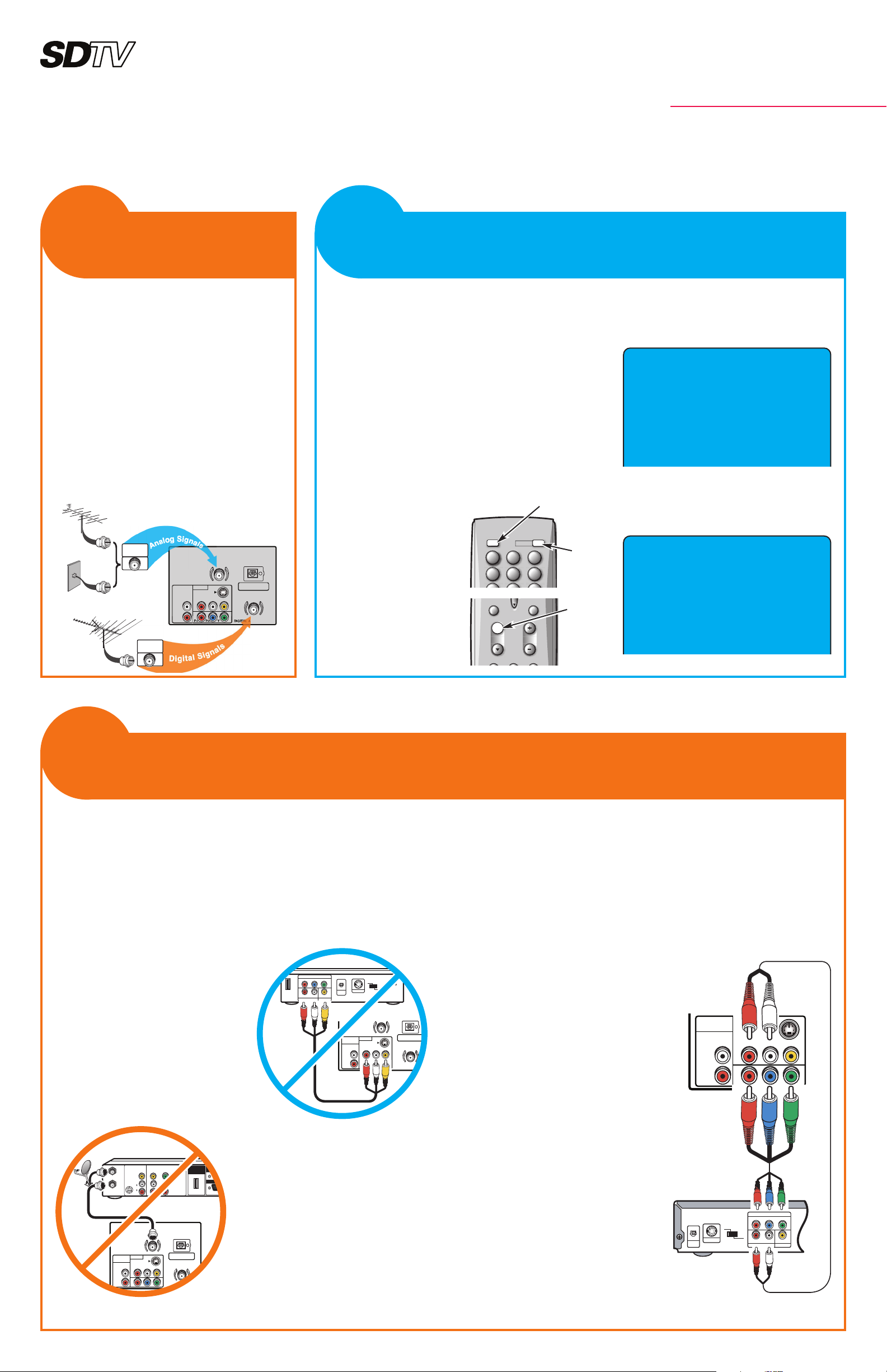
The standard analog AV and S-Video composite connectors are
included on your new DTV to provide continued compatibility with
older analog devices, such as a VCR.
The S-Video connector will provide the best resolution. If you have an
S-Video connector on your old analog equipment, you should use it
instead of the standard video connector.
1
Connect your external equipment as shown here, matching connector colors to jack colors. (Cables are not supplied.)
2
Use the INPUT key on the remote control to select Video 2 to watch video from
equipment connected to the VIDEO2 Composite jacks.
NOTES:Composite and Component VIDEO2 inputs share the same audio inputs,
therefore, you can connect only one device at a time to the VIDEO2 inputs.
Connect other analog device to the Front AV jacks (VIDEO1). Refer to the
owner’s manual for instructions.
S-Video
Audio/Video
Analog Device
CHOOSE THE BEST CONNECTION
FOR YOUR ANALOG EQUIPMENT
44
tthh
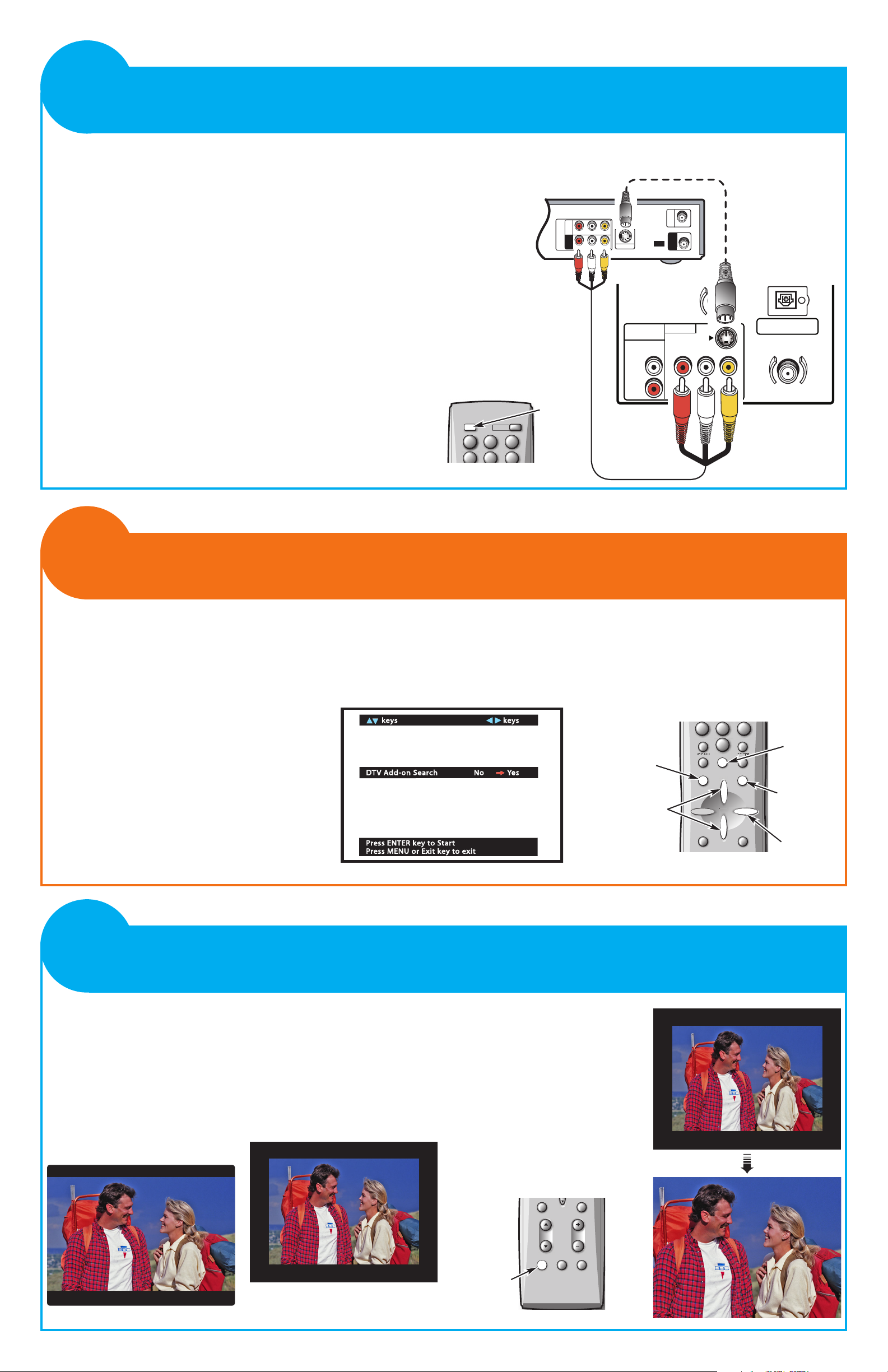
The aspect ratio (ratio of the width
to the height) of the broadcast
image and the aspect ratio of the
original program material all
affect picture shape.
Identifying Picture Shapes
Letterbox—This describes a wide
screen image displayed on a 4:3
aspect ratio screen.
Postage Stamp—This describes
an image that has a black border
surrounding the picture (images
fail to fill screen both vertically
and horizontally). This can occur
when the broadcaster upconverts
4:3 programming to wide screen
format (16:9).
Use the PIX SHAPE key to adjust
the image to suit your personal
preference. Available shapes may
vary by broadcast and input mode.
Available options are Pix1, Pix2,
and Pix3.
NOTE: The shapes available to you
depend on the aspect ratio of the
broadcast signal and the input
mode. They may differ in appearance from those represented here.
IDENTIFYING PICTURES SHAPES
AND PIX SHAPE KEY OPERATION
66
tthh
Simulated TV Images
34
R-AUDIO-L
R-AUDIO-L VIDEO
VIDEO
VHF/UHF
TO TV
FROM ANT.
RF
CHANNEL
IN
OUT
IN
OUT
S-VIDEO OUT
VIDEO
DIGITAL ANTENNA IN
(MONO)
VIDEO2
(MONO)
S-VIDEO
UHF
VHF
CATV
R
L
Y
L
R
P
B
P
R
DIGITAL AUDIO
OUTPUT
AUDIO
OUTPUT
DTV Back
CAPTIONEXIT
VOL
RESETAUDIOPIX SHAPE
CH
PIX SHAPE
key
Postage Stamp
Zoom
DTV ADD-ON SEARCH
Use this feature to add digital channels to the
digital channel database of active channels.
If necessary, after the initial All Channel
Search, turn the antenna then use the Setup
Menu to perform a DTV Add-on Search.
Repeat these steps, as necessary, for each
transmitting tower (channel) in your area.
Log on to www.antennaweb.org for a list of
those channels.
A DTV Add-on Search will take a few minutes to complete.
NOTE: DTV Add-on Search will not affect channels
already in the digital channel database. It will
only add new channels that may be found.
1
Press the TUNER key to select the
Digital Tuner. The channel display will
begin with the letter “D,” such as, D03-1.
2
Press the MENU key.
3
Use the CURSOR LM keys to highlight DTV Add-on Search.
4
Press the CURSOR > key so the red
arrow (©) points toward Yes .
5
Press ENTER.
ADDING NEW DIGITAL CHANNELS
TO THE DIGITAL CHANNEL DATABASE
55
tthh
keys
keys
keys
keys
Picture/Sound
Pic ture /Sou nd
CH Scan Memory
CH Sc an M emor y
Menu Language
Menu Lang uage
V-Guide
V-Gui de
Digital Captions
Digit al Capt ions
Yes
Yes
No
No
All CH Search
All CH Sear ch
DTV Cable Search
DT V Ca ble Search
DTV Add-on Search
DT V Ad d-on Se arch
Press ENTER key to Start
Pre ss E NTER ke y to Start
Press MENU or Exit key to exit
Pre ss M ENU or Exit key to exi t
789
INFO
RECALL
MENU
CAPTIONEXIT
ENTER
TUNER MUTE
SLEEP
0
789
0
3
CURSOR LM
keys
1
TUNER key
M
M
>
>
1
45 6
123
POWER
INPUT
45 6
123
INPUT
key
2
MENU key
5
ENTER key
4
CURSOR >
key
Remote Control
Remote Control
Remote Control
 Loading...