

Page 1
General Installation Manual
© 2009 January, Sanyo Electric Co., Ltd. All Rights Reserved 1/1/09
General Installation Manual for SANYO
HIT© Double Photovoltaic Modules.
Please read this manual completely
before installation or use of HIT Double
modules. This manual applies to the
following products:
HIT Double 200 (HIP-200DA3)
HIT Double 195 (HIP-195DA3)
HIT Double 190 (HIP-190DA3)
HIT Double 186 (HIP-186DA3)
HIT Double 180 (HIP-180DA3)
INTRODUCTION
Thank you for choosing SANYO HIT©
Double PV modules. With proper operation
and maintenance, SANYO modules will
provide you with clean, renewable solar
electricity for many years. This manual
contains important installation, maintenance
and safety information. The word “module”
as used in this manual refers to one or
more PV modules. Retain this manual for
future reference.
Disclaimer of Liability
SANYO does not assume responsibility and
expressly disclaims liability for loss,
damage, or expense arising out of, or in
any way connected with installation,
operation, use, or maintenance by using
this manual.
SANYO assumes no responsibility for any
infringement of patents or other rights of
third parties, which may result from use of
modules.
No license is granted by implication or
under any patent or patent rights. The
information in this manual is believed to be
reliable, but does not constitute an
expressed and/or implied warranty.
SANYO reserves the right to make changes
to the product, specifications, or this
manual without prior notice.
The return of any modules will not be
accepted by SANYO unless prior written
authorization has been given by SANYO.
General Information
The installation of solar modules requires a
great degree of skill and should only be
performed by qualified licensed
professionals, including, without limitation,
licensed contractors and electricians.
WARNING
All instructions should be read and
understood before attempting to install,
wire, operate, and/or maintain the
photovoltaic module. PV modules
generate DC electrical energy when
exposed to sunlight or other light
sources. Contact with electrically active
parts of the module such as terminals
1
can result in burns, sparks, and lethal
shock whether the module is connected
or disconnected.
The shock hazard increases as modules
are connected in parallel, producing
higher current, and as modules are
connected in series, producing higher
voltage.
The installer assumes the risk of all
personal injury or property damage that
might occur during installation and
handling of modules.
To avoid injury or damage:
• Cover the entire front and back
surface of the bifacial modules with
a dense, opaque material such as a
cardboard box or heavy cloth.
• Work only in dry conditions, with
dry modules and tools.
• Do not stand or step on a module.
• Do not drop a module.
• Do not break the glass surfaces of a
module.
• Do not allow children and
unauthorized persons near the
installation site or storage area of
modules.
• Completely ground all modules
according to applicable electric
codes.
• Do not disassemble the module, or
remove any part installed by the
manufacturer.
• Do not open the cover of the
junction box.
• Wear suitable protection (gloves,
clothes, etc.) to prevent direct
contact with 30V DC or greater.
• Carry a module by its’ frame with
two or more people.
• Do not carry a module by its wires
or junction box.
• Wear non-slip gloves.
• Do not drop or place heavy items on
the surfaces of a module (such as
tools).
• Check that all other system
components (inverters, wires, racks,
balance of system materials, etc.)
are mechanically and electrically
compatible.
• Do not install the module where
flammable gases or vapors are
present.
• Never leave a module unsupported
or unsecured.
• Do not use or install broken
modules.
• Do not artificially concentrate
sunlight on a module by mirror,
Fresnel lens, magnification, etc.
• Do not touch the junction box
terminals.
• Do not change the wiring of bypass
diodes.
CAUTIONS
• Use a module for its intended
purpose only.
• Do not treat any portion of the
module with paint or adhesives, to
avoid damage to the module,
inoperable conditions, or reducing
the module’s functionality.
• HIT Double modules have bifacial
performance. These modules
produce power from both surfaces
of the module at the same time and
may generate up to 30% more
output power than its’ STC rated
value. Refer to Figure 5 for these
output electrical characteristics.
• This additional power depends upon
the level of incident light irradiance
(albedo) available to the back side of
the module, and can be increased or
decreased depending upon site
characteristics, installation design,
weather, etc.
• Treat the back side of the module
the same as the front side and avoid
objects that directly shade the solar
cells. Refer to “Notes on
installation” section.
GENERAL SAFETY
Follow all permission, installation and
inspection requirements.
• Before installing modules, contact the
appropriate authorities to determine
permissions, installation and inspection
requirements that apply to your site
and installation.
• Electrically ground modules for all
systems of any voltage. If not
otherwise specified, it is recommended
that requirements of the latest National
Electrical Code (USA) or Canadian
Electric Code (Canada) or other
national or international electrical
standards be followed. Refer to “Earth
Ground Wiring” section.
• Check applicable building codes to
ensure that the construction or
structure (roof, facade, support, etc.)
where the modules are being installed
has enough strength.
• For modules mounted on roofs, special
construction or structures may be
required to help provide proper
installation support.
• Both roof construction and module
installation design have an effect on
the fire resistance of a building.
Improper installation may contribute to
fire hazards. Additional devices such
Page 2
General Installation Manual
14
27
27
φ8
Installation (refe
rence)
(4
)
© 2009 January, Sanyo Electric Co., Ltd. All Rights Reserved 1/1/09
as ground faults, fuses, and
disconnects may be required.
• Do not use modules of different
specifications in the same series string.
• Do not use modules of different
specifications in parallel.
• Check and follow all safety precautions
of other system components used.
UL Listing Information
To satisfy UL standard 1703 requirements,
when installing modules, be sure to:
• Use only stranded or solid copper
single–conductor type UF cable or
USE cable, rated sunlight resistant, for
modules and interconnect wiring that is
exposed to weather.
• Observe the requirements described in
sections labeled INSTALLTION and
SPECIFICATIONS.
INSTALLATION
General
Please read this guide completely before
installation or use of the modules. This
section contains electrical and mechanical
specifications needed before using your
SANYO PV modules.
• Modules should be firmly fixed in place
in a manner suitable to withstand all
expected loads, including wind and
snow loads.
• Metals used in locations that are
exposed to moisture shall not be
employed alone or in combinations that
could result in deterioration.
• Install modules where they are not
shaded by obstacles like buildings and
trees. Especially pay attention to avoid
partially shading modules by objects
during the daytime.
• Modules are water resistant, but not
waterproof. Moisture may leak through
where the frame and glass connect.
• Please contact your SANYO
Authorized Representative with
questions regarding mounting profiles
for modules if needed.
Notes on Installation
• Clearance between the roof surface
and module frame is required to allow
cooling air to circulate under the back
side of the module. This also allows
any condensation or moisture to
dissipate. Install modules so that air
can circulate between the roof and the
module as freely as possible.
• Leave 4 inches of clearance between
the roof and the module frame.
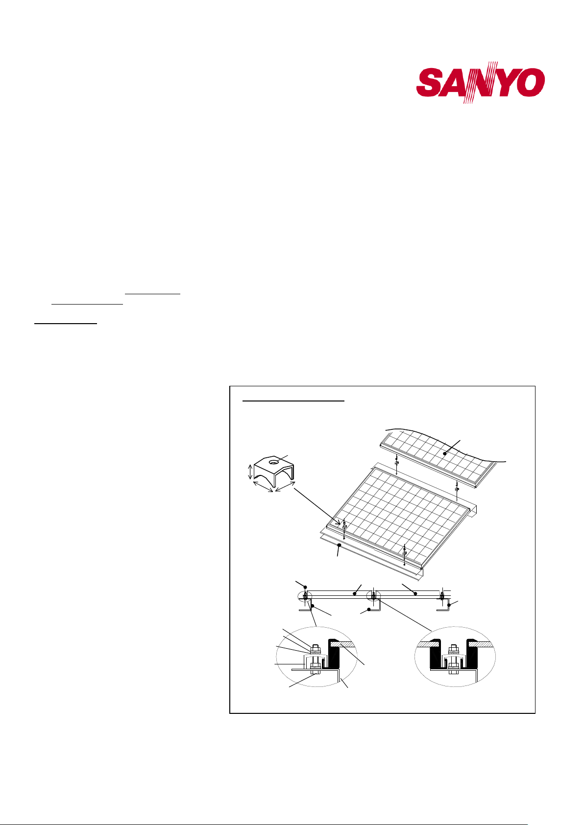
• SANYO recommends (but does not
require) the installation method and
mounting profile shown in Figure 1.
• A module should be attached on a
mount or support structure rail by metal
fittings (Size: 27x27x14mm, Material;
SUS304 or NSSC180). The metal
fitting must meet the following
specifications. Size: not less than 1.06’’
(27mm) width
Thickness: not less than 0.12’’ (3 mm)
Material: Stainless steel
• Bolting torque must be more than 8N.m.
The following information is provided to
help customers obtain good performance
without exceeding a module’s operating
conditions or warranty parameters.
• Do not artificially concentrate sunlight
on a module by mirror, Fresnel lens,
magnification, etc.
• The surface upon which modules are
installed is recommended to be flat, to
prevent artificially concentrated
sunlight.
• Additional output power from the back
face of the panel can be increased or
decreased depending upon angles of
installation, height from surfaces,
shade from structures or rails, and the
This referential figure is for HIT Double
(HIP-xxxDA3) modules
Metal fitting
Metal fitting
M6 Nut
Spring washer
Flat washer
Metal fitting
M6 Bolt/setscrew
places
Mounting
Structure Rail
End of Module
albedo of surrounding surfaces.
• Please see Figure 5 for the effect of
angles of installation on output power.
• The height of a module above a
surface affects the power potential of
the module’s back face.
• When possible, maximize the height of
modules above surfaces in order to
maximize ambient light beneath the
modules.
• Always position support structures and
rails along the edges of a module, or
between modules, and do not allow
rails to shade a module’s back surface.
• Light colored surfaces reflect more light
than dark colored surfaces. Installing
HIT Double modules over light colored
surfaces will increase the output power
potential from the back side.
Operating Conditions
SANYO requires that modules be operated
within the following conditions:
1) Terrestrial applications only—no outer
space use.
2) The ambient temperature must be
within –20°C (-4°F) to 46°C (115°F).
Solar Module
Solar Module
Mounting
Structure Rail
Mounting Structure Rail
Module
Mounting Structure Rail
Between Modules
Figure 1. Installation
2
Page 3

General Installation Manual
Module Ground Position
© 2009 January, Sanyo Electric Co., Ltd. All Rights Reserved 1/1/09
The temperature limits are defined as
the monthly average low and high of
the installation site.
3) The wind pressure load of the
installation site should be less than
1,440Pa (30PSF)*.
*Note: HIT Double modules were
tested at 30PSF at UL’s testing lab.
Modules of exactly the same structure
successfully achieved 50PSF load
ratings at JET’s (Japan Electrical
Safety & Environment Technology
Laboratories) testing lab, and are
certified as fully compliant at 50PSF.
4) Modules must not be installed nor
operated in areas where, salt, hail,
snow, sand, dust, air pollution,
chemically active vapors, acid rain,
soot, etc., are excessive.
SPECIFICATIONS
• Rated electrical characteristics are
within –5% to +10% of the values
measured at STC. STC Conditions are;
Irradiance of 1000W/m2, 25oC cell
temperature, and solar spectral
irradiance per IEC 60904-3.
• Under normal conditions, a
photovoltaic module may experience
conditions that produce more current
and/or voltage than reported at
Standard Test Conditions. Accordingly,
the values of Isc and Voc marked on
modules should be multiplied by a
factor of 1.25 when determining
voltage ratings, conductor capacities,
fuse sizes, and size of controls
connected to the module output.
Refer to Section 690 of the National
Electrical Code (NEC) for an
additional multiplying factor of 1.25,
which may be applicable.
• The current output for the modules
shown in the SPECIFICATIONS
section is measured at Standard Test
Conditions. These conditions may not
be frequently observed in actual
practice.
Mechanical Loading
• HIT Double modules should be
mounted at four (4) symmetrical
quarter points within the shaded areas
(Range A) shown in Figure 4, or any
mounting method with a continuous
attachment, by which those four points
are included in each side.
• The four symmetrical quarter point
method offers a maximum loading of
1,440Pa (30PSF) in a static state on
the module surface.
Note: This mechanical loading value
was tested using the following
mounting device:
3
Provider: AKATSUKI Industries, Ltd.
Part number: PVK-AJ4B
Note: HIT Double modules were tested
at 30PSF at UL’s testing lab. Modules
of exactly the same structure
successfully achieved 50PSF load
ratings at JET’s (Japan Electrical
Safety & Environment Technology
Laboratories) testing lab, and are
certified as fully compliant at 50PSF.
WIRING
• All wiring should be done in
accordance with applicable electrical
codes.
• Wiring methods should be in
accordance with the NEC in the USA
or the CEC in Canada.
• A qualified, licensed professional
should do all wiring.
• Wiring should be protected to help
ensure personal safety and to prevent
its damage.
• All modules connected in series should
be of the same model number and/or
type.
• Do not connect modules in parallel
without using a connection box.
• Use caution and design the system in
consideration of the increased output
power (Pmax) and current (Isc) from
the bifacial effect (see Table 1).
• Additional electrical values are
provided up to 30% beyond the STC
values for accurate system sizing
including the bifacial effect.
• If in doubt about the expected power
potential from the bifacial effect for
your particular site, please use the
values stated under the 30%
column.
Module Wiring
• The number of modules that can be
wired in series is recommended at
seven (7) or fewer. If connecting
eight (8) modules in series, check
local temperature conditions and
follow the National Electric Code
(690.7) to ensure compliance with
maximum voltage limitations. Also,
be sure to calculate and account for
the bifacial effect of the modules.
• HIT Double modules are not
designed for “off-grid” or battery
charging systems, because of their
operating voltage. Therefore, it is
not recommended to use them to
charge batteries.
• These modules contain factory
installed bypass diodes. If these
modules are incorrectly connected
to each other, the bypass diodes,
cable, or junction box may be damaged.
Array Wiring
• The term “array” is used to describe
the assembly of several modules on a
support structure with associated
wiring.
• Use copper wire that is sunlight
resistant and is insulated to withstand
the maximum possible system open
circuit voltage.
• Check local codes for requirements.
Earth Ground Wiring
• Grounding should be carried out by
attachment to the module or array
frame, to avoid the hazards of electric
shock or fire.
• The array frame shall be grounded in
accordance with NEC Article 250
(USA) or CEC in Canada.
• Each framed module has a 0.16”
diameter (4 mm) hole marked “G” in
the shorter side frame rail (see Figure
2), to connect a grounding conductor to
the module’s metal frame.
• Bonding shall be by a positive means,
such as clamping, riveting, bolting,
screwed connectors, welding, soldering,
or brazing.
• The bolt and nut size must be M3
(0.12” diameter (3 mm)).
• Washers are required as part of the
grounding connection. A star-washer is
required in order to penetrate the
coating of the frame in order to ensure
a good ground connection between the
grounding hardware, lead, and frame.
Ground Location (1 place)
Junction Box
Backside
The ground hole is
on the inside of the
module frame.
Figure 2.
Page 4

General Installation Manual
© 2009 January, Sanyo Electric Co., Ltd. All Rights Reserved 1/1/09
The star-washer’s material shall be
made of stainless steel in order to
avoid corrosion when in contact with
other metal types. The size of the starwasher as well as the size of any other
washers used will be M3 (0.12”
diameter (3mm)). The star-washer
shall be placed between the module’s
metal frame and the grounding
conductor.
• The grounding lead size must be
greater than 6mm2 (No.10 AWG), and
its type shall be sunlight-resistant UF
cable or USE-2 cable.
• Maximum torque value for the
connection must be 2.7 N.m (24 in-lb).
Module Terminations
• A junction box as a terminal enclosure
is equipped for electrical connections.
• Modules are equipped with MC3TM
plugs as a terminal enclosure. Use
these MC3TM plugs for electrical
connections.
Junction Box and Terminals
• Modules equipped with one junction
box and contain terminals for both
positive and negative polarity, and
bypass diodes.
• One terminal is dedicated to each
polarity; with the polarity symbols
engraved onto the body of the junction
box (see Figure 3).
Conduit
• For applications where wire conduits
are used, follow the applicable codes
for outdoor installation of wires in
conduits.
• Verify that all fittings are properly
installed to protect wires against
damage and prevent moisture intrusion.
Bypass Diodes
• When modules in series strings are
partially shaded, it may cause reverse
voltage across the cells or modules,
because the current from other cells in
the same series is forced to flow
through the shaded area. This may
cause undesirable heating to occur.
• The use of a diode to bypass the
shaded area can minimize both heating
and array current reduction.
• Modules are equipped with four (4)
factory installed bypass diodes. The
factory-installed diodes provide proper
circuit protection for the systems within
the specified system voltage, so that
you do not need any other additional
bypass diodes.
MAINTENANCE
• Some maintenance is recommended to
maintain optimal output performance of
the HIT Double solar modules.
• When a module’s front or back surface
becomes dirty, power output is reduced.
• It is recommended to clean the front
surface of the module with water and a
soft cloth or sponge, twice or more per
year. It is recommended to clean the
back surface as needed.
• A mild non-abrasive detergent may be
applied for persistent dirt.
• It is also recommended to inspect the
electrical and mechanical connections
annually.
• If you need electrical or mechanical
inspection or maintenance, it is
recommended to have a licensed
authorized professional carry out the
inspection or maintenance to avoid the
hazards of electric shock or injury.
For further information, please visit
www.sanyo.com/solar or contact your
SANYO Authorized Representative.
Connector
MCTM Plug
negative ( - )
Cable
Cable
Connector
MCTM Plug
positive ( + )
Figure 3. Configuration of Junction Box
4
Page 5

General Installation Manual
Dimensions
© 2009 January, Sanyo Electric Co., Ltd. All Rights Reserved 1/1/09
SPECIFICATIONS
HIT Double Series (HIP-xxxDA3)
Specifications
Cell Number in Series [Pieces]
Cell Type
Maximu m System Voltage [V]
Bypass Diodes
Panel Area
Panel We ight
Panel Dimensions LxWxH
Cable Lengths
Cable Size / Connector Type
Static Wind / Snow L oad
Pallet Dimensions LxWxH
Full Pallet Quantity / Full Pallet W eight
Quantity per 20', 40', 53' Container
HIT Double Series (HIP-xxxDA3)
Dimensions in mm
898
HIT* (hybrid of amorphous and monocrystalline silicon)
60
(107)
96
600
4 Bypass Di odes
2
13.06 f t
(1.21m2)
50.7 lbs. (23kg)
53.2x35.35x2.36in (1351x898x60mm)
39.4in each (1000mm )
No.12 A WG / MC3TM Connectors
50PSF (2400Pa) / 39PSF (1876Pa)
54.3x36x70.1in (1379x912x1781mm)
20pcs / 1 014Lbs (460kg)
200pcs / 420pcs / 54 0pcs
Ground (1 place)
Junction Box
(449)
(620)
1351
(620)
392
Front
392
Mount Locations
Side
Note: A module should be installed on support structure rails in
Note: A module should be installed on a support structure rail
accordance with the following: Use four symmetrical mounting
points within set range A.
using four (4) symmetrical attachment points within Range A.
Range A
Negative (-)
Connector (MC™ Plug)
Backside
1
Section A-A’
Positive (+)
60
7
7
19.3
5
Figure 4. Dimensions
Page 6

General Installation Manual
Electrical
S
pecifications
I
ncluding
B
ifacial
Effect
P mono
facial
Figure
5.
Installation angles and output changes
.
10
40 50 60 70 80 90
°
))))
Normalized
[
bifacial /
°
]
P bifacial
UP
’
10
40 50 60 70 80 90
o
)
bifacial
UP
Table 1
.
Specifications Including Bifacial Effect
© 2009 January, Sanyo Electric Co., Ltd. All Rights Reserved 1/1/09
Model
HIT Double 200
HIT Double 195
HIT Double 190
HIT Double 186
HIT Double 180
Maxim um Pow e r (Pmax)
Maxim um Pow e r V oltage (V pm )
Maxim um Pow e r Curr ent (Ipm )
Open Cir cuit Voltage (Voc)
(HIP-200DA3)
Short Circuit Curr ent (Is c)
Maxim um Pow e r (Pmax)
Maxim um Pow e r V oltage (V pm )
Maxim um Pow e r Curr ent (Ipm )
Open Cir cuit Voltage (Voc)
(HIP-195DA3)
Short Circuit Curr ent (Is c)
Maxim um Pow e r (Pmax)
Maxim um Pow e r V oltage (V pm )
Maxim um Pow e r Curr ent (Ipm )
Open Cir cuit Voltage (Voc)
(HIP-190DA3)
Short Circuit Curr ent (Is c)
Maxim um Pow e r (Pmax)
Maxim um Pow e r V oltage (V pm )
Maxim um Pow e r Curr ent (Ipm )
Open Cir cuit Voltage (Voc)
(HIP-186DA3)
Short Circuit Curr ent (Is c)
Maxim um Pow e r (Pmax)
Maxim um Pow e r V oltage (V pm )
Maxim um Pow e r Curr ent (Ipm )
Open Cir cuit Voltage (Voc)
(HIP-180DA3)
Short Circuit Curr ent (Is c)
Rated
STC
1
Specif ications Including Backside Irradiat ion Contribution
in Isc as a Percen t of STC
5% 10% 15% 20% 25% 30%
W 200 209 219 228 237 246 256
V 56.2 56.3 56.3 56.4 56.4 56.5 56.5
A 3.56 3.72 3.88 4.04 4.20 4.36 4.52
V 68.8 69.0 69.1 69.2 69.4 69.3 69.6
A 3.75 3.94 4.13 4.31 4.50 4.69 4.88
W 195 204 213 222 231 240 249
V 55.8 55.8 55.8 55.9 56.0 56.0 56.1
A 3.50 3.66 3.82 3.97 4.13 4.29 4.45
V 68.7 68.9 69.0 69.1 69.2 69.2 69.5
A 3.73 3.92 4.10 4.29 4.48 4.66 4.85
W 190 199 208 216 225 234 243
V 55.3 55.3 55.4 55.4 55.5 55.5 55.6
A 3.44 3.60 3.75 3.91 4.06 4.22 4.37
V 68.1 68.3 68.4 68.5 68.6 68.6 68.8
A 3.70 3.89 4.07 4.26 4.44 4.63 4.81
W 186 195 203 212 220 229 238
V 54.8 54.8 54.8 54.9 54.9 55.0 55.1
A 3.40 3.55 3.71 3.86 4.01 4.16 4.32
V 67.5 67.7 67.8 67.9 68.0 68.0 68.2
A 3.68 3.86 4.05 4.23 4.42 4.60 4.78
W 180 188 197 205 213 222 230
V 54.4 54.4 54.5 54.5 54.6 54.6 54.6
A 3.31 3.46 3.61 3.76 3.91 4.06 4.21
V 67.0 67.2 67.3 67.4 67.5 67.5 67.7
A 3.62 3.80 3.98 4.16 4.34 4.53 4.71
1
STC: Cell Temp. 25oC, AM1.5, 1000W/m
2
Pmax is normalized to that of a monofacial module at an inclination angle of 30°
1.6
1.6
30
rated
1.4
1.4
1.2
1.2
Pmax
Normalized Pmax
1.0
1.0
0.8
0.8
Pmax
0.6
0.6
Pmax
0.4
0.4
0.2
0.2
0.0
0.0
Horizontal installation
Horizontal installation
Albedo of ground (Concrete) : 55%
Albedo of ground (Concrete): 55%
Installation height : 1m
Installation height: 1m
15%
5
1111
HIT solar cell
Front incident light
Front incident light
Tempered glass
Tempered glass
0
0
20 30
20 30
HIT solar cell
Angle of Inclination (Degrees
6
Albedo =
P rated
monofacial
Rear incident light
Rear incident light
Angle of inclination (
EVA
EVA
Surface
concrete
Concrete Surface
<As an example>
Vertical installation
Vertical installation
 Loading...