

Sanyo HIP-205NKHE6, HIP-210NKHE6-2, HIP-205NKHE6-2, HIP-210NKHE6 User Manual
General Installation Manual
General Installation Manual for SANYO
HIT Photovoltaic Modules. Please read
this manual completely before
installation or use of SANYO modules.
This manual applies to the following
products:
HIP-210NKHE6, HIP-210NKHE6-2,
HIP-205NKHE6, HIP-205NKHE6-2
INTRODUCTION
Thank you for choosing SANYO HIT
photovoltaic (PV) modules. With proper
operation and maintenance, SANYO HIT
PV modules will provide you with clean,
renewable solar electricity for many years.
This manual contains important
installation, maintenance and safety
information. The word “module” as used in
this manual refers to one or more PV
modules. Retain this manual for future
reference.
Disclaimer of Liability
SANYO does not assume responsibility
and expressly disclaims liability for loss,
damage, or expense arising out of, or in
any way connected with installation,
operation, use, or maintenance by using
this manual.
SANYO assumes no responsibility for any
infringement of patents or other rights of
third parties, which may result from use of
modules.
No license is granted by implication or
under any patent or patent rights. The
information in this manual is believed to
be reliable, but does not constitute an
expressed and/or implied warranty.
SANYO reserves the right to make
changes to the product, specifications, or
manual without prior notice.
General Information
The installation of solar modules requires
a great degree of skill and should only be
performed by qualified licensed
professionals, including, without limitation,
licensed contractors and licensed
electricians.
WARNING
• All instructions should be read and
understood before attempting to
install, wire, operate, and maintain
the photovoltaic module. Contact
with electrically active parts of the
module such as terminals can
result in burns, sparks, and lethal
shock whether the module is
connected or disconnected.
• The installer assumes the risk of
all injury that might occur during
installation, including, without
limitation, the risk of electric shock.
• PV modules generate DC electrical
energy when exposed to sunlight
or other light sources. Although
single modules produce only a low
voltage and current, shocks and
burns are still a potential hazard.
• To avoid the hazard of electric
shock and injury, cover the entire
front surface of the PV modules
with a dense, opaque material such
as a cardboard box, during
installation and handling of the
modules.
• The shock hazard increases as
modules are connected in parallel,
producing higher current, and as
modules are connected in series,
producing higher voltages.
• The shock hazard increases as
modules with nominal open-circuit
voltage (Voc) in excess of 50 V,
and/or modules rated for maximum
system voltage in excess of 50 V.
• To avoid the hazard of electric
shock, work only in dry conditions,
with dry modules and dry tools.
• Do not stand or step on a module
to avoid the hazard of injury and
damage to the module.
• Do not puncture or damage the
back sheet of a module, to avoid
the hazard of electric shock and
fire.
• To avoid the hazard of electric
shock and injury, children and
unauthorized persons should not
be allowed near the installation of
PV modules.
• To avoid the hazard of electric
shock and injury, be sure to
completely ground all modules.
• To avoid the hazard of electric
shock, fire, and injury, do not
disassemble the module, or
remove any part installed by the
manufacturer.
• Unauthorized persons—except the
qualified licensed professional—
should not open the cover of the
junction box to avoid the hazard of
electric shock.
• Do not touch terminals while a
module is exposed to light. Provide
suitable guards to prevent yourself
from direct contact with 30 VDC or
greater to avoid the hazard of
electric shock or injury.
• When carrying a module, two or
more people should carry it by its
frame and wear non-slip gloves (to
avoid injury by a slipping module,
to a foot, or cuts by the edge of a
frame, and so on).
• Do not carry a module by its wires
or junction box, to avoid the
hazard of electric shock, injury or
damage to the module.
• Do not drop anything on the
surfaces of a module, to avoid the
hazard of electric shock, injury,
and damage.
• To avoid the hazard of electric
shock and fire, be sure that all
other system components are
compatible, and they do not
subject the module to mechanical
or electrical hazards.
• Since sparks may occur, do not
install the module where
flammable gases or vapors are
present.
• Never leave a module unsupported
or unsecured.
• Do not drop a module.
• Do not use or install broken
modules to avoid the hazard of fire,
electric shock, and injury.
• Do not artificially concentrate
sunlight on a module to avoid the
hazard of fire or damage.
• Do not touch the junction box
terminals to avoid the hazard of
electric shock and injury.
• Do not change the wiring of
bypass diodes to avoid the hazard
of electric shock and injury.
• Do not disconnect terminals while
PV modules generate electricity
and connect electrical load to
avoid the hazard of electrical
shock.
CAUTIONS
• Use a module for its intended
purpose only.
• Do not treat the back sheet or front
surface with paint or adhesives, to
avoid reducing its’ functionality,
damage, inoperable conditions,
and other unknown troubles.
GENERAL SAFETY
Follow all permission, installation and
inspection requirements.
• Before installing modules, contact the
appropriate authorities to determine
permissions, installation and
inspection requirements, which
should be followed.
• Be sure that the construction or
structure (roof, etc.) where the
modules are being installed has
enough strength.
• For modules mounted on roofs,
special construction or structures may
be required to help provide proper
installation support.
• Both roof construction and module
installation design have an effect on
the fire resistance of a building.
Improper installation may contribute
to fire hazards. Additional devices
such as ground fault, fuses, and
disconnects may be required.
• Do not use modules of different
specifications in the same system.
• Follow all safety precautions of other
system components used.
1
General Installation Manual
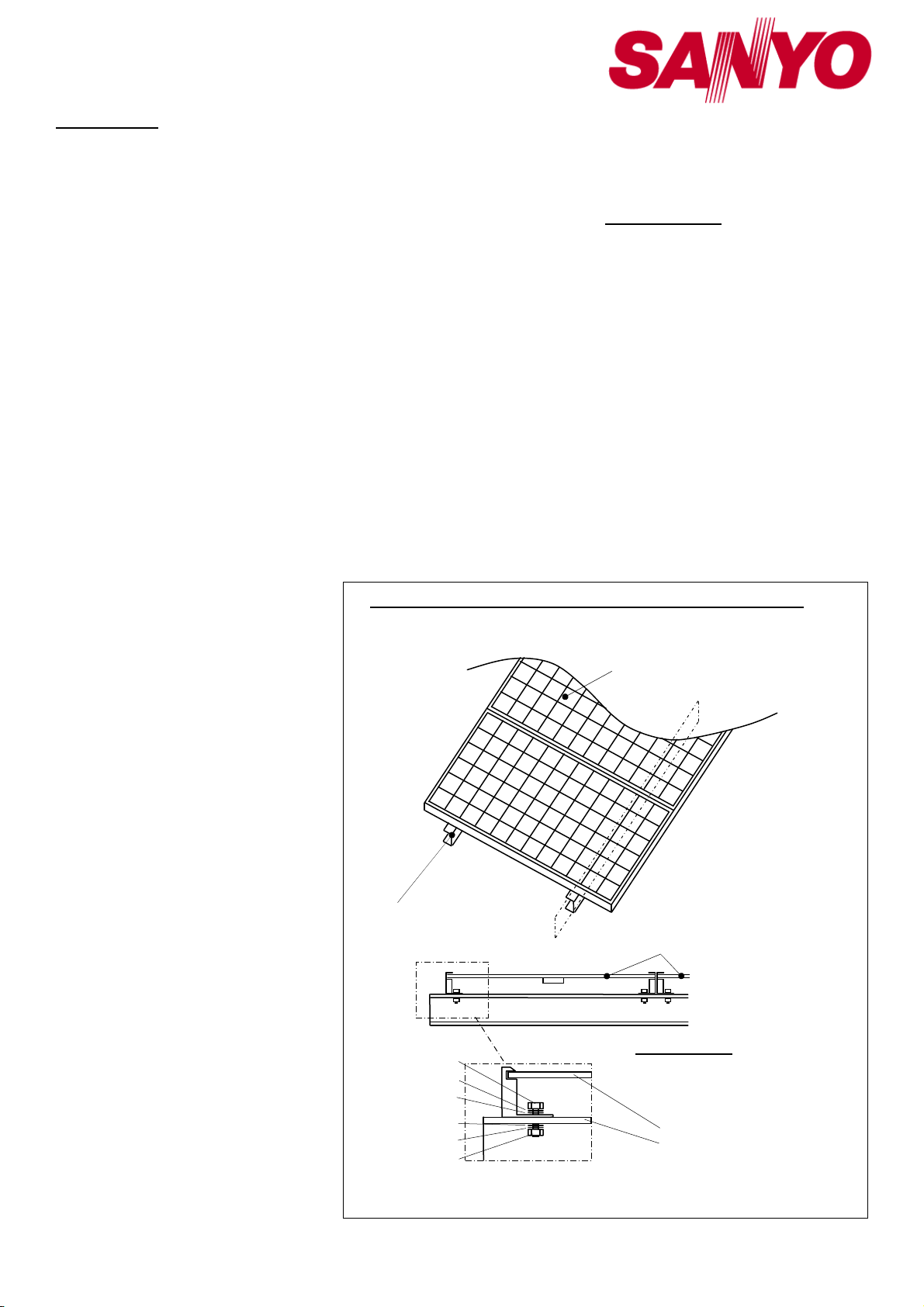
Spring washer
Flat washer
Flat washer
Spring washer
INSTALLATION
General
• Please read this guide completely
before installation or use of the
modules. This section contains
electrical and mechanical
specifications needed before using
your SANYO PV modules.
• Modules should be firmly fixed in
place in a manner suitable to
withstand all expected loads,
including wind and snow loads.
• The drilling and addition of ground
holes is permitted, but should be
avoided whenever possible to avoid
damage to the module. When
additional ground holes are
necessary, they must not penetrate
the inner side of the aluminum frame.
Caution is advised to avoid
accidentally drilling, scratching, or
penetrating the back sheet surface of
the module. If required, it is
recommended to add additional
ground holes to the outer aluminum
lip area of the module. In such case,
additional ground holes must be at
least 65 mm away from any frame
corner.
• For a non-integral module or panel,
the assembly is to be mounted over a
fire resistant roof covering rated for
the application.
• Appropriate material should be used
for mounting hardware to prevent the
module frame, mounting structure,
and hardware itself from corrosion.
• Install modules where they are not
shaded by obstacles like buildings
and trees. Especially pay attention to
avoid partially shading the modules
by objects during the daytime.
• Please contact your SANYO
Authorized Representative with
questions regarding mounting profiles
for modules if needed.
Notes on Installation
• Clearance of “10 cm” between the
roof surface and module frame is
required to allow cooling air to
circulate around the back of the
module. This also allows any
condensation or moisture to dissipate.
Install modules so that air can
circulate between the roof and the
module.
• We recommend installation methods
shown in Figure 1. In some areas,
local electrical codes may govern the
installation and use of PV modules.
• To avoid the hazard of the electric
shock and fire, do not contact and
damage the back sheet of the module
with mounting bolts.
Operating Conditions
SANYO recommends that modules be
operated within the following Operating
Conditions. An installation location with
conditions beyond the Operating
Conditions or with other Special
Conditions (see below) should be avoided.
Operating Conditions of SANYO modules
are as follows:
1) The modules should be operated only
in terrestrial applications. No space or
other Special Conditions (see below).
2) The ambient temperature should be
within –20°C (-4°F) to 40°C (104°F).
3) The relative humidity should be within
45% to 95%.
4) The wind pressure load of the
installation site should be less than
2,400N/m2 (50PSF).
Special Conditions
1) The ambient temperature and
installation place are different from
the recommended Operating
Conditions.
2) Salt damage is severe at the
installation place.
3) Hail and snow damage is excessive
at the installation place.
Installation (reference) – HIP-xxxNKHE6, xxxNKHE6-2
For questions regarding mounting profiles for modules, please contact your local dealer.
Mounting Structure Rail
M6 Bolt
M6 Nut
4) Sand and dust damage is excessive
at the installation place.
5) Air pollution, chemically active vapors,
acid rain, and/or soot, etc. are
excessive at the installation place.
SPECIFICATIONS
Notes on Specifications
1) Rated electrical characteristics are
within 10% of the values measured at
Standard Test Conditions (STC).
Irradiance of 1000W/m2, 25oC cell
temperature, and solar spectral
irradiance per IEC 60904-3.
2) Under normal conditions, a
photovoltaic module may experience
conditions that produce more current
and/or voltage than reported at
standard component test conditions.
Accordingly, the values of Isc and
Voc should be multiplied by a factor
of 1.25 when determining voltage
ratings, conductor capacities, fuse
sizes, and size of controls connected
to the module output.
3) The current output for the modules
shown in the Specifications is
measured at Standard Test
Conditions. These conditions may
Solar Module
A
Solar Module
Section A-A
Figure 1: Installation
A
Module
Mounting Structure Rail
2
 Loading...