

Page 1
General Installation Manual
© Jun 2011, Sanyo Electric Co., Ltd. All Rights Reserved 6/13/11
General Installation Manual for SANYO HIT® Photovoltaic
Modules. Please read this manual carefully before installing
or using SANYO modules. This manual applies to the
following HIT Power products:
HIT Power 220N (HIP-220NKHA5, NKHA6)
HIT Power 215N (HIP-215NKHA5, NKHA6)
HIT Power 210N (HIP-210NKHA5, NKHA6)
HIT Power 205N (HIP-205NKHA5, NKHA6)
HIT Power 200N (HIP-200NKHA5, NKHA6)
HIT Power 195N (HIP-195NKHA5, NKHA6)
INTRODUCTION
Thank you for choosing SANYO HIT photovoltaic (PV) modules.
With proper operation and maintenance, SANYO HIT PV modules
will provide you with clean, renewable solar electricity for many
years. This manual contains important installation, maintenance
and safety information. The word “module” as used in this manual
refers to one or more PV modules. Retain this manual for future
reference.
Disclaimer of Liability
SANYO does not assume responsibility and expressly disclaims
liability for loss, damage, or expense arising out of, or in any wa y
connected with installation, operation, use, or maintenance by
using this manual.
SANYO assumes no responsibility for any infringement of p atents
or other rights of third parties, which may result from use of
modules.
No license is granted by implication or under an y patent or patent
rights. The information in this manual is believed to be r eliable, but
does not constitute an expressed and/or implied warranty.
SANYO reserves the right to make changes to the product,
specifications, data sheets and this manual without prior notice.
General Information
The installation of solar modules requires a great degree of skill
and should only be performed by qualified licensed profession als,
including, without limitation, licensed contractors and electricians.
WARNING
• All instructions should be read and understood before
attempting to install, wire, operate, and maintain a
photovoltaic module.
• Contact with electrically active parts of the module such
as terminals can result in burns, sparks, and lethal shock
whether the module is connected or disconnected.
• The installer assumes the risk of all injury that might
occur during installation, including, without limitation, the
risk of electric shock.
• PV modules generate DC (direct current) electrical energy
when exposed to sunlight or other light sources. E ven a
single module produces enough voltage and current, to
cause shocks and burns if safety precautions are not
followed.
• The shock hazard increases as modules are connected in
parallel, producing higher current, and as modules are
connected in series, producing higher voltages.
• To avoid the hazard of electric sparks, shock, fire, burns,
damage and injury:
• Work only in dry conditions, with dry modules and dry
tools.
• Do not stand or step on modules. Do not puncture, cut,
scratch or damage the backsheet of a module.
Backsheet damage will void a module’s Limited
Warranty and may cause fire. Never use modules with a
damaged back sheet.
• Do not allow children and unauthorized persons near
the installation or storage site of modules.
• Completely ground all modules.
• Do not disassemble a module, attempt any repair, open
the junction box cover, nor remove any parts installed
by Sanyo. There are no user serviceable parts within
the module or junction box.
• Unauthorized persons - except the qualified licensed
professional - should not perform any electrical work,
including wiring,
• Wear suitable clothing, guards, eye protection and
gloves to prevent you from direct contact with 30 VDC
or greater.
• Wear non-slip gloves and carry modules by the frame
using both hands. Do not attempt to carry a module by
yourself.
• Do not carry a module by its wires or junction box.
• Do not drop anything on the surface of a module.
• Ensure all system components are compatible, and
they do not subject the module to mechanical or
electrical hazards.
• Sparks may occur; do not install modules where
flammable gases or vapors are present.
• Never rest or leave a module unsupported or
unsecured.
• Do not drop modules.
• Do not use or install broken modules.
• Do not artificially concentrate sunlight on a module.
• Do not touch the junction box terminals.
• Do not change the wiring of bypass diodes.
• Do not touch a PV module unnecessarily. The glass
surface and frames get hot. There is a risk of burn.
CAUTIONS
• Use a module for its intended purpose only.
• Do not treat the back sheet, frame, or front surface with
paint or adhesives, to avoid reducing its’ functionality,
damage, and causing inoperable conditions, and other
unknown troubles.
GENERAL SAFETY
Follow all permissions, installation and inspection
requirements.
• Before installing modules, contact the appropriate authorities
having jurisdiction to determine permissions, installation and
inspection requirements, which should be followed.
• Electrically ground modules for all systems of any voltage. If
not otherwise specified, it is recommended that requirements
of the latest National Electrical Code (USA) or Canadian
Electric Code (Canada) or other national or international
electrical standards be followed. Refer to “Earth Ground
Wiring” section for more information.
• Be sure that the building or structure (roof, façade, etc.) where
the modules are being installed has enough strength to
support the load of the modules.
• For modules mounted on roofs, special structures may be
required to help provide proper installation support.
• Both, roof construction and module installation design have an
effect on the fire resistance of a building. Improper installation
1
Page 2
General Installation Manual
© Jun 2011, Sanyo Electric Co., Ltd. All Rights Reserved 6/13/11
may contribute to fire hazards. Additional devices such as
ground fault, fuses, and disconnects may be required.
• Do not use modules of different specifications in the same
system.
• Follow all safety precautions of other system components
which are used.
UL Listing Information
To satisfy UL requirements, when installing the modules, be sure
to:
1) Use only stranded or solid copper single–conductor sunlightresistant cable rated for outdoor use (e.g. type UF or USE) ,
for all wiring that is exposed to weather.
2) Observe the requirements described in sections labeled
INSTALLATION
INSTALLATION
General
Please read this guide completely before installing or using your
Sanyo PV modules. This section contains important electrical and
mechanical specifications..
• Modules should be firmly fixed in place in a manner suitable to
withstand all expected loads, including wind and snow loads.
• Metals used in locations that are exposed to moisture shall
not be employed alone or in combinations that could result in
deterioration or corrosion.
• Install modules where they are not shaded by obstacles like
buildings and trees. Pay special attention to avoid partially
shading the modules by objects during the daytime.
• If needed, contact an Authorized Representative with
questions regarding mounting profiles for Sanyo modules.
Notes on Installation
• Clearance between the roof surface and module frame is
required to allow cooling air to circulate around the back of
the module. This also allows any condensation or moisture to
dissipate. Install modules with a minimum of 1 inch clearance
between the roof surface and the modules so that air can
circulate.
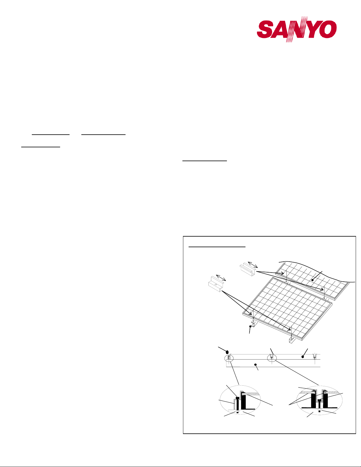
• SANYO recommends the installation method and mounting
profile shown in Figure 1
• A module should be attached on a mount or support
structure rail by corrosive-resistant met al clamps.
•
The clamps should be made of aluminum alloy or other
material that will reasonably protect against the a risk
of electrolytic corrosion.
• Recommendation of bolt torque range: 16N.m to 20N.m
•
The module was tested using Unirac clamps with the
specifications below; if a different clamp is used it must
have a design load capacity equivalent to or greater
than the load specified in this Manual.
¾ Provider: UniRac, Inc.
¾ Part number: SolarMount®
¾ Clamps type: Top Mounting Clamps
¾ Clamp size:Mid clamp and End clamp, F size,
¾ Unirac Part No.320029, 320102
¾ Width: 1.5” (38 mm)
¾ Thickness : 0.12”(3 mm)
¾ Torque range: 16N.m to 20N.
¾ Material: Aluminum Alloy
and SPECIFICATIONS.
2
• Sanyo does not provide a warranty for clamps. The modul e
warranty Sanyo provides shall be voided if clamps selected
by the customer are of an improper material or size.
.
Operating Conditions
SANYO requires that modules are operated within the following
Operating Conditions:
1) Terrestrial applications only—no outer space or Special
Conditions (see below).
2) The ambient temperature mus t be within –20°C (-4°F) to 46°C
(115°F). The temperature limits are defined as the Monthly
Average High or Low of the installation site.
3) The wind pressure load of the installation site should be less
than 2,880N/m2 (60PSF)
4) Some environmental conditions could apply. Please refer to
Sanyo’s warranty exclusions.
SPECIFICATIONS
Notes on Specifications
1) Rated electrical characteristics are within –5% to +10% of the
values measured at Standard Test Conditions (STC). STC
conditions are; Irradiance of 1000W/m, 25
and solar spectral irradiance per IEC 60904-3. Note: At the
time of shipment, Sanyo guarantees the output level of its
modules to be -0/+10% against Rated Power in
SPECIFICATIONS based on Sanyo’s factory inspection at
STC conditions. Under real conditions, a photovoltaic module
may experience conditions that produce more current and/or
voltage than reported at Standard Test Conditions. Therefore,
Installation (reference)
38mm
38mm
Metal clamp B
(2 places)
Metal clamp A
(2 places)
Mounting
Metal clamp B Solar Module
Mounting Structure Rail
Metal clamp B
Module
Mounting StructureM8 Nut
Figure 1. Installation
Metal clamp A
M8 Bolt
Metal clamp A
Structure Rail
End of Module Between Modules
o
C cell temperature,
Solar Module
M8 Bolt
M8 Nut
Page 3
General Installation Manual
(
© Jun 2011, Sanyo Electric Co., Ltd. All Rights Reserved 6/13/11
the Isc value of modules should be multiplied by a factor of
1.25 to determine ampacity. An additional factor of 1.25 may
be required for sizing conductors, fuses, disconnects, etc.
Please refer to section 690.8 of the National Electric Code
(NEC) for guidelines. The Voc must be factored according to
the lowest recorded ambient temperature recorded for the
location where the modules will be installed. Please refer to
section 690.7 of the NEC for more information regarding
voltage temperature factors.
3) The current output for the modules shown in the
SPECIFICATIONS section is measured at Standard Test
Conditions. These conditions may not be frequently observed
in actual practice.
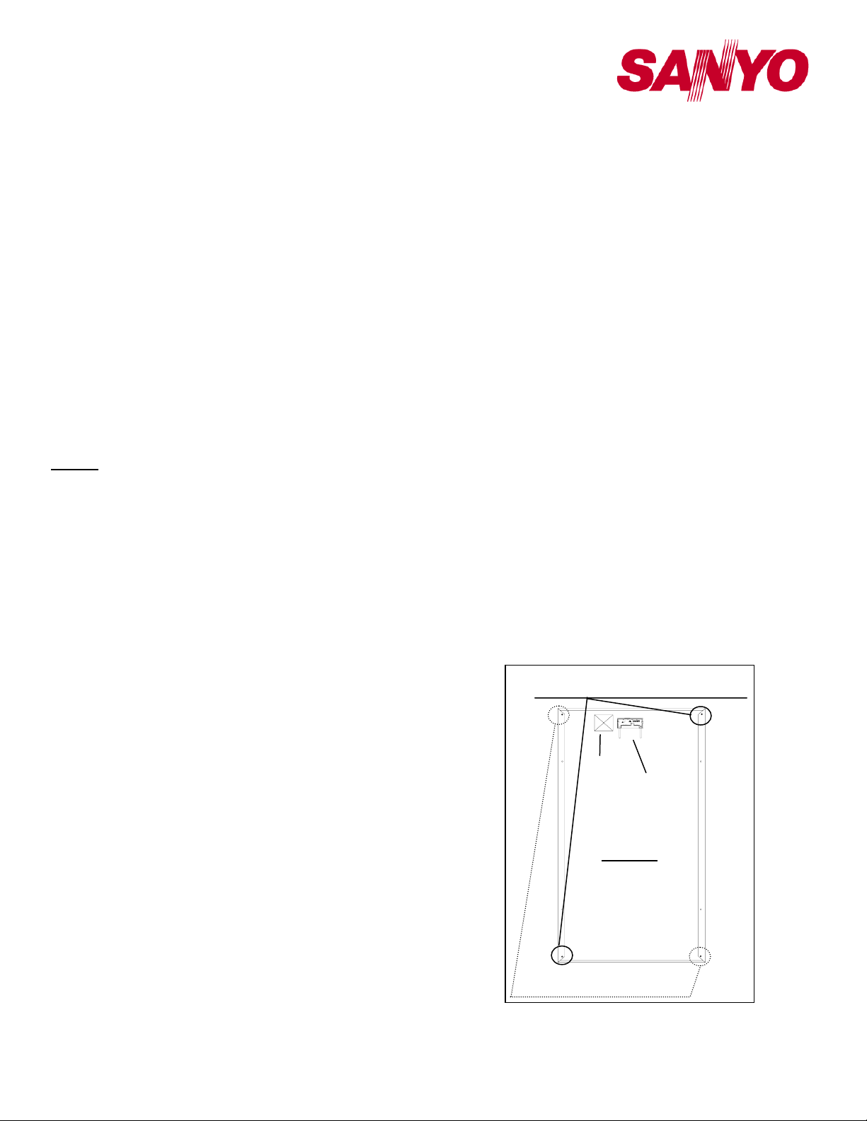
Mechanical Loading
• The modules should be mounted at the four (4) quarter points
by the means shown in Figure 2.
• This method offers a maximum load of 2,880N/m2 (60PSF) in
a static state on the module surface.
Note: This mechanical loading value was tested using the
mounting device specified in section “Notes on Installation”.
WIRING
General
• All wiring should be done in accordance with applicable
• Wiring methods should be in accordance with the NEC in USA
• A qualified, licensed professional should do all wiring.
• Wiring should be protected to help ensure personal safet y and
• All modules connected in series should be of the same model
• Do not connect modules in parallel without using a connection
Module Wiring
• The number of modules that can be wired in series is
• Modules are not designed for “off-grid” or battery charging
• These modules contain factory installed bypass diodes. If
• Do not disconnect terminals while PV modules generate
• To avoid the hazard of electric shock and sparks, please
• Cable conduits should be used in locations where the wiring is
electrical codes.
or CEC in Canada.
to prevent damage.
number and/or type.
box that connects appropriate FUSE for each series string or
each module.
recommended to be ten (10) or fewer. If connecting eleven
(11) modules in series, check local temperature conditions
and follow the National Electric Code (690.7) to ensure
compliance with maximum voltage limitations.
systems, because of their operating voltage. Therefore, it is
not recommended to use them for charging batteries.
these modules are incorrectly connected to each other, the
bypass diodes, cable, or junction box may be damaged.
electricity and connect electrical load to avoid the hazard of
electrical shock.
connect each cable after confirming the polarity of them is
correct.
inaccessible to children or small animals.
Array Wiring
• The term “array” is used to describe the assembly of several
modules on a support structure with associated wiring.
• Use copper wire which insulation is sunlight resistant and can
withstand the maximum possible system open circuit voltage.
• Interconnection of modules must be performed in a
professional fashion. Wires should be secured and only
reasonable slack should be allowed.
• Check local codes for requirements.
Earth Ground Wiring
• All modules should be grounded. All structures or metallic
components in direct contact with the modules or electric
wires should be properly grounded too. To avoid the hazards
of electric shock or fire, modules should be grounded by the
frame only at the locations marked in this manual (see
grounding methods below).
• T he array frame shall be grounded in accordance with NEC
Article 250 (USA) or the CEC in Canada.
• Bonding shall be by a positive means, such as clamping,
riveting, bolted or screwed connectors, or welding, soldering
or brazing. If the bonding means depends upon screw threads
two or more screws or two full threads of a single screw must
engage the metal
• Great care should be exercised to ensure that corrosion
caused by the grounding means be avoided.
• Corrosion can increase the resistance of the grounding
connection on the module, or can even cause the grounding
connection to fail entirely. Corrosion can be caused by the
effects of weather, humidity, dirt and so on. It can also be
caused when two dissimilar metals are in contact (galvanic
reaction).
¾ The module frame material is aluminum/magnesium alloy.
¾ All fasteners (nuts, bolts, washers, screws, etc.) must be
stainless steel unless otherwise specified.
• Length of self-tapping screw or bolt should not be more than
Ground Location
(smaller holes for self-tapping screw)
PVU-B50.2
IP6
5
600
V
PVU-B50.2
Label
Junction Box
Backside
The ground holes
are on the backside of
the module frame.
Ground Location
larger holes for bolt and nut)
Figure 3.1
Module Ground Position
3
Page 4

General Installation Manual
© Jun 2011, Sanyo Electric Co., Ltd. All Rights Reserved 6/13/11
0.78’’ (20 mm) in order to avoid contacting the back-sheet of
the module.
• Acceptable grounding wire is following.
Ilsco Corp. GBL-4DBT 10-14AWG-Solid, 4-6, 8, 10-14AWGStrand
Burndy L L C CL501TN 14AWG-Solid, 14-4AWG-Strand
Tyco Electronics Corp. 1954381-1/1954381-2 10-12AWG
Solid
• Each ledge on the module frame has two smaller holes for
self-tapping screws (0.165’‘diameter (4.2 mm)) and two larger
holes for bolts (0.205’‘diameter (5.2 mm)). These ground
holes are marked with a “G” adjacent to their location on t he
frame rail (see Figure 3.1).
• Ground wires must be connected to the module’s metal
frame at one of these locations.
• Lay-in lugs or grou nding clips can be used to ground Sanyo
HIT modules. Both methods are explained below, please
choose one.
Grounding Locations (or grounding holes)
Using a self tapping screw. (see Figures 3.2 and 3.4)
• If using this method, use one of the smaller holes with
diameter of 0.165’‘ (4.2 mm)
• The self-tapping screw size must be No.10 (0.190’‘diameter
(4.83mm)).
• This method requires a minimum number of threads-per-inc h
to achieve an adequate electrical connection. For a single
screw, the thread pitch must be at least 32 threads per inch
(TPI). A single screw less than 32 TPI does not provide
sufficient thread contact. Note: Self-tapping screws are also
called thread cutting screws.
• Recommended torque value in tightening self tapping screw is
2.3 N.m (20in-lb).
Using bolt and nut (see Figures 3.3 and 3.5)
• If using this method, use one of the larger holes with diameter
of 0.205’‘ (5.2 mm)
¾ The bolt and nut size should be No.8 (0.164’‘diameter (4.16
mm)), or No.10 (0.190’‘diameter (4.83 mm)) or M5
(0.197’‘diameter (5.0 mm)).
• Star washers must be used to make contact through the
anodization of the module frame.
• In this case, the screw threads are not providing the electrical
ground contact.
• Recommended torque value in tightening bolt and nut is 2.3
N.m (20in-lb).
Grounding Methods
Wire connection using cup washers (see Figures 3.2 and
3.3)
• The use of cup washers is to prevent wire from slipping out
from under the screw head (and/or the flat washer).
• Make sure that the cup washer is placed between the wire
and the module frame.
• Choose an adequate size for the cup washer and the flat
washer so that the wire is fully clamped between them.
• Note: Cup washers are also called terminal cup washers.
• The cup washers should be stainless steel, or a cup washer
made of brass may be used only if a large flat washer made of
stainless steel is inserted between the module frame and the
cup washer.
• Choose the adequate size for the lar ge flat washer (between
• If using this method, use one of the smaller holes with
• T he self-tapping screw size must be No.10 (0.190’‘ diameter
• This method requires a minimum number of threads-per-inch
• If using this method, use one of the larger holes with
• Star washers must be used to make contact through the
• In this case, the screw threads are not providing the electrical
Using lay-in lug with self tapping screw
• If using this method, please follow instructions in previous
• Use a grounding tin plated solid copper lay-in lug rated for
• The self-tapping screw size must be No.10 (0.190’‘diameter
• This method requires a minimum number of threads-per-inch
• As shown in figure 3.4, attach grounding lug to module frame
• Insert a stainless steel star washer between the module
• Tighten stainless steel set screw at the torque specified by
• Recommended torque value in tighte ning self tapping screw
the module frame and the cup washer) so that the cup washer
doesn’t contact the module frame and is fixed stably to the
module frame.
Method 1- Use a self tapping screw (see Figures 3.1 and 3.2)
diameter of 0.165’‘ (4.2 mm)
(4.83mm)).
to achieve an adequate electrical connection. For a single
screw, the thread pitch must be at least 32 threads per inch
(TPI). A single screw less than 32 TPI does not provide
sufficient thread contact. Note: Self-tapping screws are also
called thread cutting screws.
Method 2- Use a bolt and nut (see Figures 3.1 and 3.3)
diameter of 0.205’‘ (5.2 mm)
• The bolt and nut size should be No.8 (0.164’‘ diameter
(4.16 mm)), or No.10 (0.190’‘ diameter (4.83 mm)) or
M5 (0.197’‘ diameter (5.0 mm)).
anodization of the module for this method.
ground contact.
section regarding using self tapping screws.
direct burial and outdoor use. Lug must be used ILSCO
GBL-4DBT, Burndy CL501TN.
(4.83mm)).
to achieve an adequate electrical connection. For self-tapping
screws, the thread pitch must be at least 32 threads per inch
(TPI). A single screw less than 32 TPI does not provide
sufficient thread contact. Note: Self-tapping screws are also
called thread cutting screws.
using a stainless steel self tapping screw.
frame and the lug to penetrate frame anodization.
lug manufacturer to secure copper wire.
The specified torque is following
Ilsco Corp. GBL-4DBT
10-14AWG-Solid -> 20 in-lbs,
4-6AWG-Strand -> 35 in-lbs, 8AWG-Strand -> 25 in-lbs, 1014AWG-Strand -> 20 in-lbs
Burndy L L C CL501TN
14AWG-Solid -> 35 in-lbs,
14AWG-Strand -> 35 in-lbs, 4AWG-Strand -> 45 in-lbs
s 2.3 N.m (20in-lb).
4
Page 5

General Installation Manual
© Jun 2011, Sanyo Electric Co., Ltd. All Rights Reserved 6/13/11
Using a lay-in lug with bolt and nut
• If using this method, please follow instructions in previous
section regarding using bolts and nuts with larger groundi ng
holes.
• Use a grounding tin plated solid copper lay-in lug rated for
direct burial and outdoor use. Lug must be used ILSCO
GBL-4DBT, Burndy CL501TN.
• Attach grounding lug to module frame using a stainless steel
bolt and lock-nut as shown in figure 3.5.
• Tighten stainless steel set screw at the torque specified by
lug manufacturer to secure copper wire.
• Recommended torque value in tightening bolt and nut is 2.3
N.m (20in-lb).
Using a Grounding Clip with self- tapping screw
• Use T yco Electronics 1954381-1 as grounding clip.
• As shown in figure 3.6, place the grounding clip onto the
module frame.
• Thread the screw into the hole until the h ead is flush with the
base and base is flush with the frame, then tighten the screw
with 1/4 to 1/2 turn.
Recommended torque value in tightening self tapping screw
is between 2.3 and 2.8 Nm.
• Insert the wire into the wire slot. Press down on both ends of
the wire.
• Manually, or using channel lock pliers, push the slider over
the base until it covers the base. This will terminate the wire.
• For more information, please refer to Instruction sheet issued
by Tyco Electronics.
Using a Grounding Clip with bolt and nut
• Use Tyco Electronics 1954381-2 as grounding clip.
• As shown in figure 3.7, place the grounding clip onto the
module frame.
• Thread the hex nut onto the end of the scr ew, then using a
3/8-in. wrench, tighten the nut.
Recommended torque value in tightening bolt and nut is
between 1.7 and 2.2 Nm.
• Insert the wire into the wire slot. Press down on both ends of
the wire.
• Manually, or using channel lock pliers, push the slider over
the base until it covers the base. This will terminate the wire.
• For more information, please refer to Instruction sheet issued
by Tyco Electronics.
Module Terminations
A junction box as a terminal enclosure is equipped for electrical
connections.
Modules are equipped with MC
Use these MC
TM
plugs for electrical connections.
TM
plugs as a terminal enclosure.
Junction Box and Terminals
• Modules are equipped with one junction box containing
terminals for both, positive and negative polarity, and bypass
diodes.
• Each terminal is dedicated to one polarity with the polarity
symbols engraved onto the body of the junction box (see
Figure 4)
• Each terminal is provided with factory installed lead cables
and a latching connector for series and string connections.
Always use these connectors and do not detach them from
cables.
• Latching connectors are type IV and made by Multi-Contact.
Supplied connectors listed by UL.
• In order to comply with NEC 2008, a locking sleeve nee ds to
be used with all connectors that are exposed.
• The locking sleeve (PV-SSH4) is made by Multi-Contact and
can only be released with a special tool also made by
Multicontact (PV-MS). Locking sleeves are not supplied with
modules and must be purchased separately.
Conduit
• In applications where wire raceways or conduit are used,
follow the applicable codes for outdoor installations..
• Verify that all fittings are properly installed to protect wires
against damage and prevent moisture intrusion.
DIODES
Bypass Diodes
• When modules in series strings are partially shaded, it may
cause reverse voltage across cells or modules, because the
current from other cells in the same series is forced to flow
through the shaded area. This may cause undesirable heating
to occur.
• The use of a diode to bypass the shaded area can minimize
both heating and array current reduction.
• Modules are equipped with factory installed bypass diodes.
The factory-installed diodes provide proper circuit protection
PVU-B50.2
IP6
5
600
V
PVU-B50.2
Cable
Connector
TM
MC
Plug
Option:
Safety lock clip
Negative ( - ) Positive ( + )
Figure 4 Configuration of
Junction Box
5
Page 6

General Installation Manual
© Jun 2011, Sanyo Electric Co., Ltd. All Rights Reserved 6/13/11
for the systems within the specified system voltage, so that
you do not need any other additional bypass diodes.
• Contact your SANYO Authorized Representative for proper
diode type, if it is necessary to add or change diodes due to
system specifications.
MAINTENANCE
• Some maintenance is recommended to maintain optimal
output performance of the solar modules.
• If the module surface becomes dirty, it may reduce output
power.
• It is recommended to clean the surface of the module with
water and a soft cloth or sponge, twice or more per year.
• A mild non-abr asive detergent may be applied for persistent
dirt.
• It is also recommended to inspect the electrical and
mechanical connections annually.
• If you need electrical or mechanical inspection or
maintenance, it is recommended to have a licensed
authorized professional carry out the inspection or
maintenance to avoid the hazards of electric shock or injury.
The return of any modules will not be accepted by SANYO unless
prior written authorization has been given by SANYO.
As part of SANYO’s policy of continuous improvement, SANYO
reserves the right to change product specifications at any time
without prior notice.
For further information, please visit sanyo.com/solar
contact your SANYO Authorized Representative.
or
6
Page 7

General Installation Manual
© Jun 2011, Sanyo Electric Co., Ltd. All Rights Reserved 6/13/11
Cup washer (Terminal cup)
(Stainless steel or *brass)
Flat washer (Stainless steel)
Spring washer (Stainless steel)
Self-tapping screw (Stainless steel)
#10-32
Frame (Longer side)
Grounding hole
(0.165’‘ diameter (4.2 mm) )
Glass
Backsheet
*Flat washer (Stainless steel)
Ground wire (#12AWG)
(wound around the screw)
Length
(not less than 0.47’‘(12 mm)
not more than 0.78’‘(20 mm))
Figure 3.2 (Method 1)
Grounding method
using self-tapping screw
Note: Use the smaller
ground
holes illustrated in Figure
3.1.
*If using a brass cup washer, a flat washer must be inserted between the cup washer and
module frame, and the flat washer diameter must be greater than the cup washer diameter.
Glass
Frame (Longer side)
Nut (Stainless steel)
Flat washer (Stainless steel)
Star washer (Stainless steel)
Cup washer (Terminal cup)
(Stainless steel or *brass)
Flat washer (Stainless steel)
Spring washer (Stainless steel)
Bolt (Stainless steel)
#8, #10, M5
Backsheet
Grounding hole
0.205’‘ diameter
(5.2 mm))
*Flat washer (Stainless steel)
Ground wire (#12AWG)
(wound around the bolt)
Length
(not less than 0.63’‘(16 mm)
not more than 0.78’‘(20 mm))
Figure 3.3 (Method 2)
Grounding method
using bolt and nut
Note: Use the larger
ground
holes illustrated in Figure
3.1.
*If using a brass cup washer, a flat washer must be inserted between the cup washer and
module frame, and the flat washer diameter must be greater than the cup washer diameter.
7
Page 8

General Installation Manual
© Jun 2011, Sanyo Electric Co., Ltd. All Rights Reserved 6/13/11
Frame (Longer side)
Copper wire
Set screw (Stainless screw)
Glass
Backsheet
Grounding hole
(0.165” diameter (4.2mm))
Star washer (Stainless steel)
Thickness:
not less than 0.02” (0.51 mm)
Diameter:
not less than 0.4” (10.16 mm)
Grounding Lug
Self-tapping screw (Stainless steel)
Length
(not less than 0.47’‘(12 mm)
not more than 0.78’‘(20 mm))
Figure 3.4
Grounding method
Using self-tapping screw
Note: Use the smaller
ground
holes illustrated in Figure 3.1.
Select a grounding the
following lug.
ILSCO GBL-4DBT,
Burndy CL501TN
Frame (Longer side)
Grounding Lug
Copper wire
Set screw (Stainless screw)
Glass
Grounding hole
(0.205” diameter (5.2mm))
Nut (Stainless steel)
Star washer (Stainless steel)
Flat washer (Stainless steel)
Thickness:
not less than 0.037” (0.94 mm)
Diameter:
not less than 0.75” (19.05 mm)
Bolt (Stainless steel)
#8, #10, M5
Length
(not less than 0.63’‘(16 mm)
not more than 0.78’‘(20 mm))
Backsheet
Figure 3.5
Grounding method
Using bolt and nut
Note: Use the larger
ground
holes illustrated in Figure 3.1.
Select a grounding the
following lug.
ILSCO GBL-4DBT,
Burndy CL501TN
8
Page 9

General Installation Manual
© Jun 2011, Sanyo Electric Co., Ltd. All Rights Reserved 6/13/11
Frame (Longer side)
Grounding hole
(0.165” diameter (4.2mm))
Self-tapping screw (Stainless steel)
Copper wire
Glass
Backsheet
Length
(not less than 0.47’‘(12 mm)
not more than 0.78’‘(20 mm))
Grounding Clip
Figure 3.6
Grounding method
Using Grounding Clip with
self-tapping screw
Note: Use the smaller
ground
holes illustrated in Figure
3.1.
Grounding Clip Assemblies:
Tyco Electronics 1954381-1.
Copper wire
Frame (Longer side)
Grounding hole
(0.205” diameter (5.2mm))
Grounding Clip
Glass
Backsheet
8-32 Screw (Stainless steel)
Length
(not less than 0.63’‘(16 mm)
not more than 0.78’‘(20 mm))
Nut (Stainless steel)
Figure 3.7
Grounding method
Using Grounding Clip with
bolt and nut
Note: Use the larger
ground
holes illustrated in Figure
3.1.
Grounding Clip Assemblies:
Tyco Electronics 1954381-2
9
Page 10

General Installation Manual
© Jun 2011, Sanyo Electric Co., Ltd. All Rights Reserved 6/13/11
SPECIFICATIONS
Elect rical Speci fications
Model HIT Power 215N HIT Power 210N HIT Power 205N HIT Power 200N
(HIP-215NKHA5,6) (HIP-210NKHA5,6) (HIP-205NKHA5,6) (HIP-200NKHA5,6)
Cell Number in Series 72 72 72 72
Rated Power, Watts (Pmax) 215 210 205 200
Maximum Power Voltage (Vpm) 42.0 41.3 40.7 40.0
Maximum Power Current (Ipm) 5.13 5.09 5.05 5.00
Open Circui t Voltage (Voc) 51.6 50.9 5 0.3 49.6
Short Circuit Current (Isc) 5.61 5.57 5.54 5.50
Cel l Type HI T HI T HI T HIT
Maximum System Voltage (Voc) 600 600 600 600
Factory Installed Bypass Diodes 3 3 3 3
Maximum Series Fuse (A) 15151515
Mechanical Speci fications
Length, mm (inches)
Width, mm (inches)
Frame Depth, mm (inches)
Weight, kg (pounds) 16 (3 5 . 3)
All HIT Power N Models (HIP-xxxNKHA5, HIP-xxxNKHA6)
Dimensions in mm
1580 (62.2)
798 (31.4)
46 (1.8)
Dimensions
Mount Locations
PVU-B50.2
IP6
5
600
V
PVU-B50.2
Label
Negative (-)
88cm
(34.6 in)
Junction Box
Positive (+)
103cm
(40.6 in)
Connector (MC TM Plug)
Ground (4 places)
Section A-A’
Front Side Backside
Note: A module should be installed on a mounting structure rail in accordance with the following
Section B-B’
>Use four (4) symmetrical mounting within setting range A.
: Range A
Figure 2 Dimensions
10
 Loading...