

Page 1
General Installation Manual
© Jun 2011, Sanyo Electric Co., Ltd. All Rights Reserved 6/13/11
General Installation Manual for SANYO
©
Double Photovoltaic Modules.
HIT
Please read this manual completely
before installation or use of HIT Double
modules. This manual applies to the
following products:
HIT Double 200 (HIP-200DA3)
HIT Double 195 (HIP-195DA3)
HIT Double 190 (HIP-190DA3)
HIT Double 186 (HIP-186DA3)
HIT Double 180 (HIP-180DA3)
INTRODUCTION
Thank you for choosing SANYO HIT
Double PV modul es. With proper operation
and maintenance, SANYO modules will
provide you with clean, renewable solar
electricity for many years. This manual
contains important installation, maintenance
and safety information. The word “module”
as used in this manual refers to one or
more PV modules. Retain this manual for
future reference.
Disclaimer of Liability
SANYO does not assume responsibility and
expressly disclaims liability for loss,
damage, or expense arising out of, or in
any way connected with installation,
operation, use, or maintenance by using
this manual.
SANYO assumes no responsibility for any
infringement of patents or other rights of
third parties, which may result from use of
modules.
No license is granted by implication or
under any patent or patent rights. The
information in this manual is believed to be
reliable, but does not constitute an
expressed and/or implied warranty.
SANYO reserves the right to make changes
to the product, specifications, or this
manual without prior notice.
The return of any modules will not be
accepted by SANYO unless prior written
authorization has been given by SANYO.
General Information
The installation of solar modules requires a
great degree of skill and should only be
performed by qualified licensed
professionals, including, without limitation,
licensed contractors and electricians.
WARNING
All instructions should be read and
understood before attempting to install,
wire, operate, and/or maintain the
photovoltaic module. PV modules
generate DC electrical energy when
exposed to sunlight or other light
sources. Contact with electrically active
parts of the module such as terminals
can result in burns, sparks, and lethal
shock whether the module is connected
or disconnected.
The shock hazard increases as modules
are connected in parallel, producing
higher current, and as modules are
connected in series, producing higher
voltage.
The installer assumes the risk of all
personal injury or property damage that
might occur during installation and
handling of modules.
To avoid injury or damage:
©
• Cover the entire front and back
surface of the bifacial modules with
a dense, opaque material such as a
cardboard box or heavy cloth.
• Work only in dry conditions, with
dry modules and tools.
• Do not stand or step on a module.
• Do not drop a module.
• Do not break the glass surfaces of a
module.
• Do not allow children and
unauthorized persons near the
installation site or storage area of
modules.
• Completely ground all modules
according to applicable electric
codes.
• Do not disassemble the module, or
remove any part installed by the
manufacturer.
• Do not open the cover of the
junction box.
• Wear suitable protection (gloves,
clothes, etc.) to prevent direct
contact with 30V DC or greater.
• Carry a module by its’ frame with
two or more people.Do not carry a
module by its wires or junction
box.Wear non-slip gloves.
• Do not drop or place heavy items on
the surfaces of a module (such as
tools).
• Check that all other system
components (inverters, wires, racks,
balance of system materials, etc.)
are mechanically and electrically
compatible.
• Do not install the module where
flammable gases or vapors are
present.
• Never leave a module unsupported
or unsecured.
• Do not use or install broken
modules.
•
Do not artificially concentrate
sunlight on a module by mirror,
Fresnel lens, magnification, etc.
• Do not touch the junction box
terminals.
• Do not change the wiring of bypass
diodes.
• Do not touch a PV module
unnecessarily. The glass surface
and frames get hot. There is a risk of
burn.
CAUTIONS
• Use a module for its intended
purpose only.
• Do not treat any portion of the
module with paint or adhesives, to
avoid damage to the module,
inoperable conditions, or reducing
the module’s functionality.
• HIT Double modules have bifacial
performance. These modules
produce power from both surfaces
of the module at the same time and
may generate up to 30% more
output power than its’ STC rated
value. Refer to Figure 5 for these
output electrical characteristics.
• This additional power depends upon
the level of incident light irradiance
(albedo) available to the back side of
the module, and can be increased or
decreased depending upon site
characteristics, installation design,
weather, etc.
• Treat the back side of the module
the same as the front side and avoid
objects that directly shade the solar
cells. Refer to “Notes on
installation” section.
GENERAL SAFETY
Follow all permission, installation and
inspection requirements.
• Before installing modules, contact the
appropriate authorities to determine
permissions, installation and inspection
requirements that apply to your site
and installation.
• Electrically ground modules for all
systems of any voltage. If not
otherwise specified, it is recommended
that requirements of the latest National
Electrical Code (USA) or Canadian
Electric Code (Canada) or other
national or international electrical
standards be followed. Refer to “Earth
Ground Wiring” section.
• Check applicable building codes to
ensure that the construction or
structure (roof, facade, support, etc.)
where the modules are being installed
has enough strength.
• For modules mounted on roofs, special
construction or structures may be
required to help provide proper
installation support.
1
Page 2
General Installation Manual
φ
© Jun 2011, Sanyo Electric Co., Ltd. All Rights Reserved 6/13/11
• Both roof construction and module
installation design have an effect on
the fire resistance of a building.
Improper installation may contribute to
fire hazards. Additional devices such
as ground faults, fuses, and
disconnects may be required.
• Do not use modules of different
specifications in the same series string.
• Do not use modules of different
specifications in parallel.
• Check and follow all safety precautions
of other system components used.
UL Listing Information
To satisfy UL standard 1703 requirements,
when installing modules, be sure to:
• Use only stranded or solid copper
single–conductor type UF cable or
USE cable, rated sunlight resistant, for
modules and interconnect wiring that is
exposed to weather.
• Observe the requirements described in
sections labeled INSTALLTION
SPECIFICATIONS
.
INSTALLATION
General
Please read this guide completely before
installation or use of the modules. This
section contains electrical and mechanical
specifications needed before using your
SANYO PV modules.
• Modules should be firmly fixed in place
in a manner suitable to withstand all
expected loads, including wind and
snow loads.
• Metals used in locations that are
exposed to moisture shall not be
employed alone or in combinations that
could result in deterioration.
• Install modules where they are not
shaded by obstacles like buildings and
trees. Especially pay attention to avoid
partially shading modules by objects
during the daytime.
• Modules are water resistant, but not
waterproof. Moisture may leak through
where the frame and glass connect.
• Please contact your SANYO
Authorized Representative with
questions regarding mounting profiles
for modules if needed.
Notes on Installation
• Clearance between the roof surface
and module frame is required to allow
cooling air to circulate under the back
side of the module. This also allows
any condensation or moisture to
dissipate. Install modules so that air
can circulate between the roof and the
module as freely as possible.
• Leave 4 inches of clearance between
the roof and the module frame.
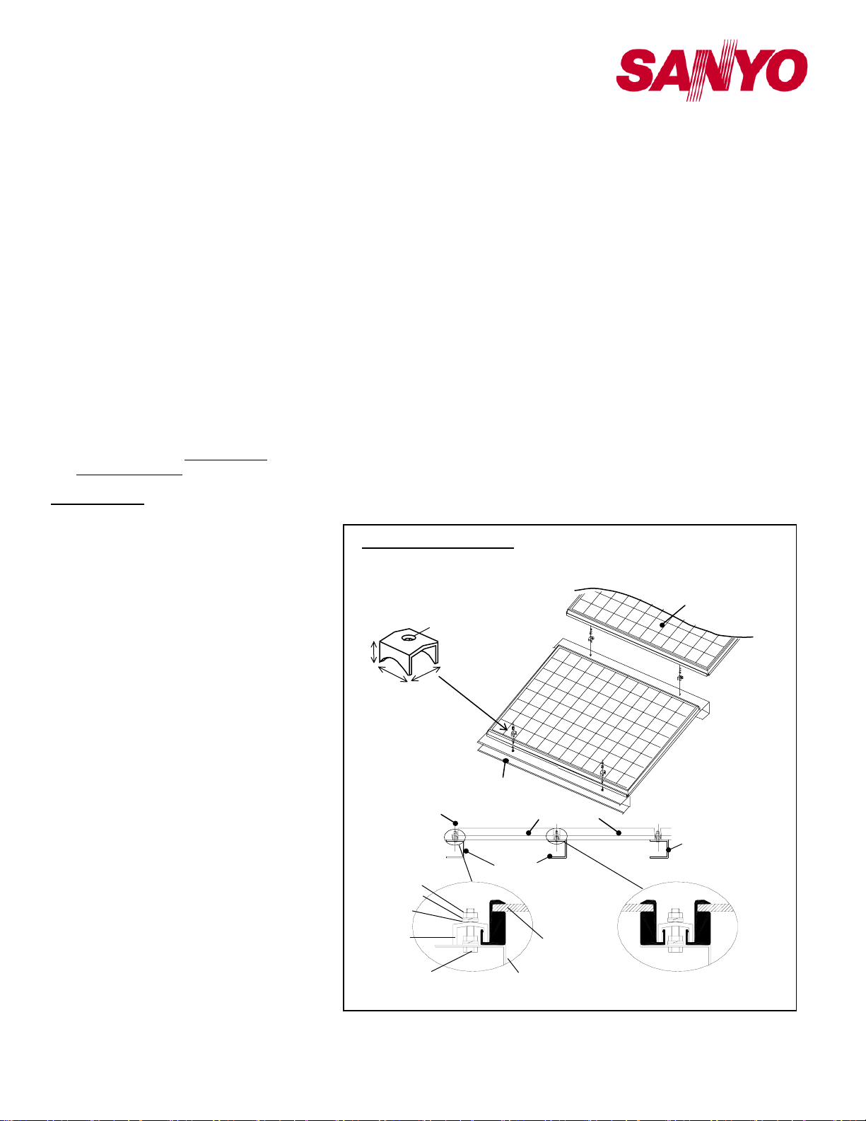
• SANYO recommends (but does not
require) the installation method and
mounting profile shown in Figure 1.
• A module should be attached on a
mount or support structure rail by metal
fittings (Size: 27x27x14mm, Material;
SUS304 or NSSC180). The metal
fitting must meet the following
specifications. Size: not less than 1.06’’
(27mm) width
Thickness: not less than 0.12’’ (3 mm)
Material: Stainless steel
• Bolting torque must be more than 8N.m.
The following information is provided to
help customers obtain good performance
without exceeding a module’s operating
conditions or warranty parameters.
• Do not artificially concentrate sunlight
on a module by mirror, Fresnel lens,
magnification, etc.
and
• The surface upon which modules are
installed is recommended to be flat, to
prevent artificially concentrated
sunlight.
Installation (reference)
This referential figure is for HIT Double
(HIP-xxxDA3, HIT-xxxDA5) modules
14
27
Spring washer
Flat washer
Metal fitting
M6 Bolt/setscrew
27
Metal fitting
(4 places)
Metal fitting
M6 Nut
End of Module
8
Mounting
Structure Rail
Mounting Structure Rail
Mounting Structure Rail
Figure 1. Installation
• Additional output power from the back
face of the panel can be increased or
decreased depending upon angles of
installation, height from surfaces,
shade from structures or rails, and the
albedo of surrounding surfaces.
• Please see Figure 6 for the effect of
angles of installation on output power.
• The height of a module above a
surface affects the power potential of
the module’s back face.
• When p ossible, maximize the height of
modules above surfaces in order to
maximize ambient light beneath the
modules.
• Always position support structures and
rails along the edges of a module, or
between modules, and do not allow
rails to shade a module’s back surface.
• Light colored surfaces reflect more light
than dark colored surfaces. Installing
HIT Double modules over light colored
surfaces will increase the output power
potential from the back side.
Operating Conditions
SANYO requires that modules be operated
Solar Module
Solar Module
Mounting
Structure Rail
Module
Between Modules
2
Page 3
General Installation Manual
© Jun 2011, Sanyo Electric Co., Ltd. All Rights Reserved 6/13/11
within the following conditions:
1) Terrestrial applications only—no outer
space use.
2) The ambient temperature must be
within –20°C (-4°F) to 46°C (115°F).
The temperature limits are defined as
the monthly average low and high of
the installation site.
3) The wind pressure load of the
installation site should be less than
1,440Pa (30PSF)*.
*Note: HIT Double modules were
tested at 30PSF at UL’s testing lab.
Modules of exactly the same structure
successfully achieved 50PSF load
ratings at JET’s (Japan Electrical
Safety & Environment Technology
Laboratories) testing lab, and are
certified as fully compliant at 50PSF.
4) Modules must not be installed nor
operated in areas where, salt, hail,
snow, sand, dust, air pollution,
chemically active vapors, acid rain,
soot, etc., are excessive.
SPECIFICATIONS
• Rated electrical characteristics are
within –5% to +10% of the values
measured at STC. STC Conditions are;
Irradiance of 1000W/m
temperature, and solar spectral
irradiance per IEC 60904-3.
• Under normal conditions, a
photovoltaic module may experience
conditions that produce more current
and/or voltage than reported at
Standard Test Conditions. Accordingly,
the values of Isc and Voc marked on
modules should be multiplied by a
factor of 1.25 when determining
voltage ratings, conductor capacities,
fuse sizes, and size of controls
connected to the module output.
Refer to Section 690 of the National
Electrical Code (NEC) for an
additional multiplying factor of 1.25,
which may be applicable.
• The current output for the modules
shown in the SPECIFICATIONS
section is measured at Standard Test
Conditions. These conditions may not
be frequently observed in actual
practice.
Mechanical Loading
• HIT Double modules should be
mounted at four (4) symmetrical
quarter points within the shaded areas
(Range A) shown in Figure 4, or any
mounting method with a continuous
attachment, by which those four points
are included in each side.
• The four symmetrical quarter point
method offers a maximum loading of
2
, 25oC cell
1,440Pa (30PSF) in a static state on
the module surface.
Note: This mechanical loading value
was tested using the following
mounting device:
Provider: AKATSUKI Industries, Ltd.
Part number: PVK-AJ4B
Note: HIT Double modules were tested
at 30PSF at UL’s testing lab. Modules
of exactly the same structure
successfully achieved 50PSF load
ratings at JET’s (Japan Electrical
Safety & Environment Technology
Laboratories) testing lab, and are
certified as fully compliant at 50PSF.
WIRING
• All wiring should be done in
• Wiring methods should be in
• A qualified, licensed professional
• Wiring should be protected to help
• All modules connected in series should
• Do not connect modules in parallel
• Do not disconnect terminals while PV
• To avoid the hazard of electric shock
• Cable conduits should be used in
• Use caution and design the system in
• Additional electrical values are
• If in doubt about the expected power
Module Wiring
• The number of modules that can be
accordance with applicable electrical
codes.
accordance with the NEC in the USA
or the CEC in Canada.
should do all wiring.
ensure personal safety and to prevent
its damage.
be of the same model number and/or
type.
without using a connection box that
connects appropriate FUSE for each
series string or each module.
modules generate electricity and
connect electrical load to avoid the
hazard of electrical shock.
and sparks, please connect each cable
after confirming the polarity of them is
correct.
locations where the wiring is
inaccessible to children or small
animals.
consideration of the increased output
power (Pmax) and current (Isc) from
the bifacial effect (see Table 1).
provided up to 30% beyond the STC
values for accurate system sizing
including the bifacial effect.
potential from the bifacial effect for
your particular site, please use the
values stated under the 30% column.
wired in series is recommended at
seven (7) or fewer. If connecting eight
(8) modules in series, check local
temperature conditions and follow the
National Electric Code (690.7) to
ensure compliance with maximum
voltage limitations. Also, be sure to
calculate and account for the bifacial
effect of the modules.
• HIT Double modules are not designed
for “off-grid” or battery charging
systems, because of their operating
voltage. Therefore, it is not
recommended to use them to charge
batteries.
• These modules contain factory
installed bypass diodes. If these
modules are incorrectly connected to
each other, the bypass diodes, cable,
or junction box may be damaged.
Array Wiring
• The term “array” is used to describe
the assembly of several modules on a
support structure with associated
wiring.
• Use copper wire that is sunlight
resistant and is insulated to withstand
the maximum possible system open
circuit voltage.
• Check local codes for requirements.
Earth Ground Wiring
• Grounding should be carried out by
attachment to the module or array
frame, to avoid the hazards of electric
shock or fire.
• The array frame shall be grounded in
accordance with NEC Article 250
(USA) or CEC in Canada.
• Bonding shall be by a positive means,
such as clamping, riveting, bolted or
screwed connectors, or welding,
soldering or brazing. If the bonding
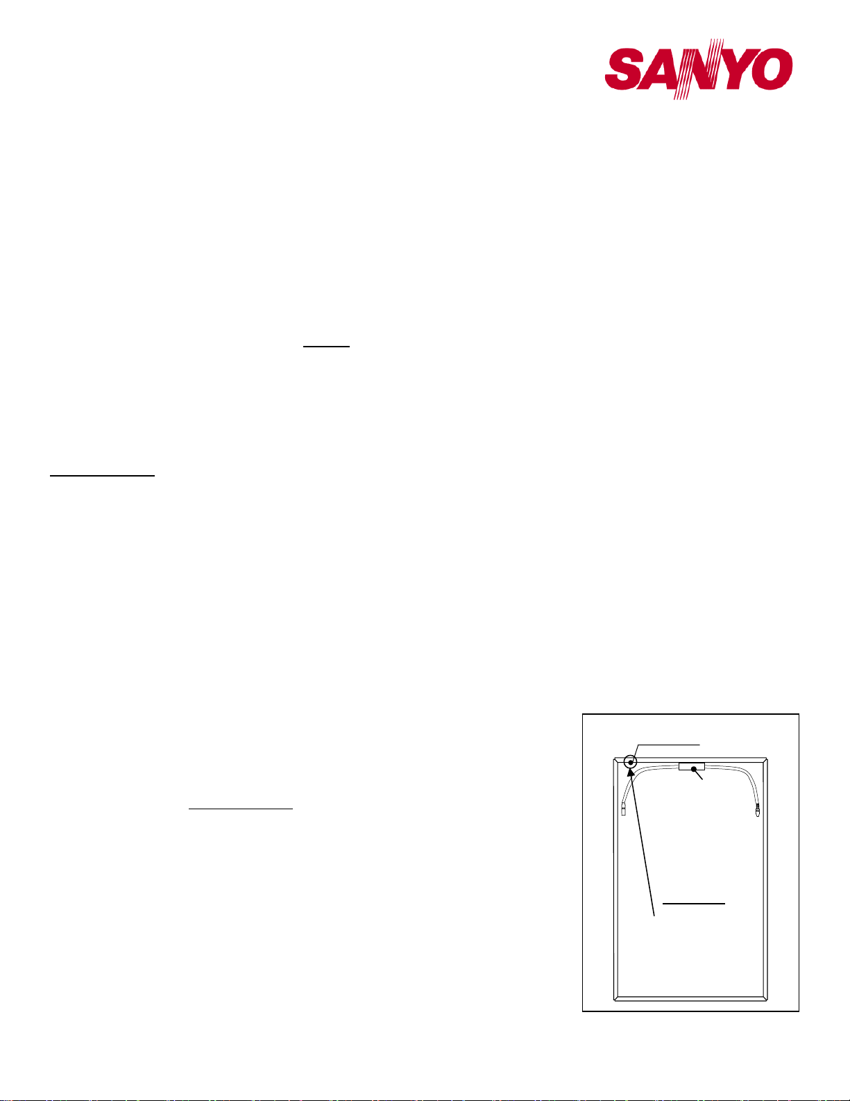
Ground Location (1 place)
Junction Box
Backside
The ground hole
is on the inside of
the module frame.
Figure 2. Module Ground Position
3
Page 4

General Installation Manual
© Jun 2011, Sanyo Electric Co., Ltd. All Rights Reserved 6/13/11
means depends upon screw threads
two or more screws or two full threads
of a single screw must engage the
metal.
• All the washers illustrated in Figure 4.1
are required as part of the grounding
connection.
• Great care should be exercised to
ensure that corrosion caused by the
grounding means be avoided.
Corrosion can increase the resistance
of the grounding connection on the
module, or can even cause the
grounding connection to fail entirely.
Corrosion can be caused by the effects
of weather, humidity, dirt and so on. It
can also be caused when two
dissimilar metals are in contact
(galvanic action).
¾ Note that the module frame material
is aluminum/magnesium alloy.
¾ All fasteners (nuts, bolts, washers,
etc.) must be stainless steel unless
otherwise specified.
• Length of bolt should not be more than
1.26’’(32 mm).
• Acceptable grounding wire is following.
Ilsco Corp. GBL-4DBT 10-14AWGSolid, 4-6, 8, 10-14AWG-Strand
Burndy L L C CL501TN 14AWG-Solid,
14-4AWG-Strand
Tyco Electronics Corp. 1954381-2 1012AWG Solid
• Each framed module has a hole for a
bolt (0.205” diameter (5.2 mm)). This
ground hole is marked with a “G”
adjacent to the location on the frame
rail (see Figure 2). Ground wires must
be connected to the module’s metal
frame at this location.
Grounding Locations (or grounding
holes)
• If using this method, use one of the
larger holes with diameter of
0.205’‘ (5.2 mm)
¾ The bolt and nut size should be No.8
(0.164’‘diameter (4.16 mm)), or
No.10 (0.190’‘diameter (4.83 mm))
or M5 (0.197’‘diameter (5.0 mm)).
• Star washers must be used to make
contact through the anodization of the
module frame.
• In this case, the screw threads are not
providing the electrical ground contact.
Grounding Method
Wire connection using cup washers
(see Figures 4.1)
・ Use a bolt and nut (see Figures 2
Figures 4.1)
・ The use of cup washers is to prevent
wire from slipping out from under the
screw head (and/or the flat washer).
・ Make sure that the cup washer is
placed between the wire and the
module frame.
・ Choose an adequate size for the cup
washer and the flat washer so that the
wire is fully clamped between them.
・ Note: Cup washers are also called as
terminal cup washers.
・ The cup washers should be stainless
steel, or a cup washer made of brass
may be used only if a large flat washer
made of stainless steel is inserted
between the module frame and the cup
washer.
・ Choose the adequate size for the large
flat washer (between the module frame
and the cup washer) so that the cup
washer doesn’t contact the module
frame and is fixed stably to the module
frame.
• Star washers must be used to make
contact through the anodization of the
module for this method.
• In this case, the scre w threads are not
providing the electrical ground contact.
• Recommended torque value in
tightening bolt and nut is 2.3N.m
(20in-lb).
Using “grounding lug . (see Figures 4.2)
Use a bolt and nut (see Figures 2 and
4.2)
• The bolt and nut size should be No.8
(0.164’‘ diameter (4.16 mm)), or No.10
(0.190’‘ diameter (4.83 mm)) or M5
(0.197’‘ diameter (5.0 mm))
• Star washers must be used to make
contact through the anodization of the
module for this method..
• In this case, the screw threads are not
providing the electrical ground contact.
As shown in Figures 4.2, tighten the
set screw (stainless steel) to ground
wire at the torque specified by lug
manufacturer.
The specified torque is following
Ilsco Corp. GBL-4DBT
10-14AWG-Solid -> 20 in-lbs,
4-6AWG-Strand -> 35 in-lbs, 8AWGStrand -> 25 in-lbs, 10-14AWG-Strand
-> 20 in-lbs
Burndy L L C CL501TN
14AWG-Solid -> 35 in-lbs,
14AWG-Strand -> 35 in-lbs, 4AWGStrand -> 45 in-lbs
• Recommended torque value in
tightening bolt and nut is 2.3N.m (20inlb).
• Use a grounding tin plated solid copper
lay-in lug rated for direct burial and
outdoor use. Lug must be used ILSCO
GBL-4DBT, Burndy CL501TN.
Using a Grounding Clip with bolt and
nut
Use a bolt and nut (see Figures 2 and
4.2)
• Use Tyco Electronics 1954381-2 as
grounding clip.
• As shown in figure2, place the
grounding clip onto the module frame.
• Thread the hex nut onto the end of the
screw, then using a 3/8-in. wrench,
tighten the nut.
Recommended torque value in
tightening bolt and nut is between 1.7
and 2.2 Nm.
• Insert the wire into the wire slot. Press
down on both ends of the wire.
• Manually, or using ch annel lock pliers,
push the slider over the base until it
covers the base. This will terminate
the wire.
• For more information, please refer to
Instruction sheet issued by Tyco
Electronics.
Additional ground hole – If needed,
drilling one hole allowed in specified
locations on the frame of the module (see
Figures 4.3(a) and (b)).This hole is for
grounding purposes only. The grounding
hole size should be 0.205” 5.2 mm.
1. Scratch the hole centers of
additional ground hole both side of
frame.
2. Fix a module and Drill the pilot holes
from outside of frame. (hole
diameter: 2 mm)
3. Fix a module and Drill the pilot holes
from inside of frame. (hole diameter:
2 mm)
4. Fix a module and Drill plated
through hole from outside of frame
(hole diameter: 5.2 mm)
5. If barr side of frame outside is more
than 1 mm, remove the barr by
using sandpaper.
WARNING
Do not damage the back side of module
when the holes are drilled.
Junction Box and Terminals
• Modules are equipped with one
junction box containing terminals for
both, positive and negative polarity,
and bypass diodes.
• Each terminal is provided with factory
installed lead cables and Multi Contact
MC3 connectors for series and string
connections. Always use these
connectors and do not detach them
from cables.
4
Page 5

General Installation Manual
© Jun 2011, Sanyo Electric Co., Ltd. All Rights Reserved 6/13/11
Bypass Diodes
• When modules in series strings are
partially shaded, it may cause reverse
voltage across the cells or modules,
because the current from other cells in
the same series is forced to flow
through the shaded area. This may
cause undesirable heating to occur.
• The use of a diode to bypass the
shaded area can minimize both heating
and array current reduction.
• Modules are equipped with four (4)
factory installed bypass diodes. The
factory-installed diodes provide proper
circuit protection for the systems within
the specified system voltage, so that
you do not need any other additional
bypass diodes.
MAINTENANCE
• Some maintenance is recommended to
maintain optimal output performance of
the HIT Double solar modules.
• W hen a module’s front or back surface
becomes dirty, power output is reduced.
• It is recommended to clean the front
surface of the module with water and a
soft cloth or sponge, twice or more per
year. It is recommended to clean the
back surface as needed.
• A mild non-abrasive detergent may be
applied for persistent dirt.
• It is also recommended to inspect the
electrical and mechanical connections
annually.
• If you need electrical or mechanical
inspection or maintenance, it is
recommended to have a licensed
authorized professional carry out the
inspection or maintenance to avoid the
hazards of electric shock or injury.
For further information, please visit
www.sanyo.com/solar
SANYO Authorized Representative.
or contact your
5
Page 6

General Installation Manual
gr
© Jun 2011, Sanyo Electric Co., Ltd. All Rights Reserved 6/13/11
Connector
TM
Plug
MC
negative ( - ) positive ( + )
Cable Cable
Figure 3-1. Configuration of Junction Box for HIP-xxxDA3
Glass
Connector
TM
Plug
MC
Star washer (Stainless steel)
Flat washer (Stainless steel)
Nut (Stainless steel)
Glass
Bolt (Stainless steel)
Length
(not less than 1.024”(26 mm)
not more than 1.26”(32 mm))
#8, #10, M5.
Frame (Shorter side)
Grounding hole
(0.205” diameter
(5.2 mm))
Spring washer (Stainless steel)
Flat washer (Stainless steel)
Ground wire (#12AWG)
(wound around the bolt)
*Flat washer (Stainless steel)
Cup washer (Terminal cup)
(Stainless steel or *brass)
*If using a brass cup washer, a flat washer must be inserted between the cup washer and module frame, and the flat
washer diameter must be
eater than the cup washer diameter.
Figure 4.1
Grounding method using cup washer
6
Page 7

General Installation Manual
© Jun 2011, Sanyo Electric Co., Ltd. All Rights Reserved 6/13/11
Set screw
(Stainless steel)
Grounding lug
Copper wire
Frame
Grounding lug
*Select a grounding
the following lug
Ilsco GBL-4DBT
Burndy CL501TN
[Top view]
Glass
Nut (Stainless steel)
[Section]
Bolt (Stainless steel)
#8, #10, M5.
Length
(not less than 1.024”(26 mm)
not more than 1.26”(32 mm))
Star washer
(Stainless steel)
Grounding hole
(0.205” diameter
(5.2 mm))
Grounding Clip
TYCO 1954381-2(SolKlip)
Copper wire
Frame
Grounding hole
(0.205” diameter
Grounding Clip
TYCO 1954381-2(SolKlip)
(5.2 mm))
[Top view]
Glass
Nut (Stainless steel)
[Section]
Bolt (Stainless steel)
#8, #10, M5.
Length
(not less than 1.024”(26 mm)
not more than 1.26”(32 mm))
Flat washer
(Stainless steel)
Thickness:
not less than 0.037” (0.94 mm)
Diameter
not less than 0.75” (19.05 mm)
Grounding method using grounding lug
Figure 4.2
7
Page 8

General Installation Manual
© Jun 2011, Sanyo Electric Co., Ltd. All Rights Reserved 6/13/11
(a) Long frame and Short frame (Not J-Box side)
0.7”
0.4”
Glass side of the module
3’ 3”
(b) Short frame (J-Box side)
0.7”
0.4”
3’ 3”
Drill in this area
Glass side of the module
5” 5”
Drill in this area
Figure 4.3
Acceptable area for drilling
8
Page 9

General Installation Manual
© Jun 2011, Sanyo Electric Co., Ltd. All Rights Reserved 6/13/11
SPECIFICATIONS
HIT Double Series (HIP-xxxDA3)
Specifications
Ce ll Numbe r in S er ies [ Pieces]
Cell Type
Maximum System Voltage [V]
Bypas s Diod es
Maximum Series Fuse (A)
Panel Area
Panel Weight
Panel Dimensions LxWxH
Cable Lengths
Cabl e Size / Connector Type
St atic Wind / Snow Load
Pall et Dimens ion s LxWxH
Full Pallet Qua ntit y / Ful l Pallet Weight
Quantity per 20', 40', 53' Container
Dimensions
HIT Double Series (HIP-xxxDA3)
HIT* (hybrid of amor phous and monocry stal l ine si licon)
96
600
4 Bypass Diodes
15
13.06 ft
2
(1.21m2)
50.7 lbs. (23kg)
53.2x35.35x2.36in (1351x898x60mm)
39.4in each (1000mm)
No.12 AWG / MC Connectors
50PS F (2400P a) / 39PSF (1876P a)
54.3x36x70.1in (1379x912x1781mm)
20pcs / 1014Lbs (460kg)
200pcs / 420pcs / 540pcs
Dimensions in mm
(620)
(620)
392
898
Front
392
60
1351
Mount Locations
Side
(107)
Negative (-)
Connector (MC
Ground (1 place)
Junction Box
™ Plug)
Backside
(449)
Positive (+)
Note: A module should be installed on support structure rails in
Note: A module should be installed on a support structure rail
accordance with the following: Use four symmetrical mounting
points within set range A.
using four (4) symmetrical attachment points within Range A.
Range A
Figure 5. Dimensions
1
Section A-A’
9
60
7
7
19.3
Page 10

General Installation Manual
/
S
ifi
© Jun 2011, Sanyo Electric Co., Ltd. All Rights Reserved 6/13/11
Electrical Specifications Including Bifacial Effect
pec
Rated
M odel STC 5% 10% 15% 20% 25% 30%
Maxim um Pow er (P m ax) W 200 209 219 228 237 246 256
Maxim um Power Voltage (V pm ) V 56.2 56.3 56.3 56.4 56.4 56.5 56.5
Maxim u m P o w e r C u rre n t (Ip m ) A 3 .5 6 3 .7 2 3 .8 8 4 .0 4 4 .2 0 4 .3 6 4 .5 2
O pen C irc u it V o ltage (V oc) V 68.8 69.0 69.1 69.2 69.4 69.3 69.6
HIT-200D A5)
(HIP-200D A 3,
HIT D ouble 200
Short C irc u it C u rre n t ( Is c ) A 3 .7 5 3 .9 4 4 .1 3 4 .3 1 4 .5 0 4 .6 9 4 .8 8
Maxim um Pow er (P m ax) W 195 204 213 222 231 240 249
Maxim um Power Voltage (V pm ) V 55.8 55.8 55.8 55.9 56.0 56.0 56.1
Maxim u m P o w e r C u rre n t (Ip m ) A 3 .5 0 3 .6 6 3 .8 2 3 .9 7 4 .1 3 4 .2 9 4 .4 5
O pen C irc u it V o ltage (V oc) V 68.7 68.9 69.0 69.1 69.2 69.2 69.5
HIT-195D A5)
(H IP-195D A3,
HIT D ouble 195
Short C irc u it C u rre n t ( Is c ) A 3 .7 3 3 .9 2 4 .1 0 4 .2 9 4 .4 8 4 .6 6 4 .8 5
Maxim um Pow er (P m ax) W 190 199 208 216 225 234 243
Maxim um Power Voltage (V pm ) V 55.3 55.3 55.4 55.4 55.5 55.5 55.6
Maxim u m P o w e r C u rre n t (Ip m ) A 3 .4 4 3 .6 0 3 .7 5 3 .9 1 4 .0 6 4 .2 2 4 .3 7
O pen C irc u it V o ltage (V oc) V 68.1 68.3 68.4 68.5 68.6 68.6 68.8
HIT-190D A5)
(HIP-190D A 3,
HIT D ouble 190
Short C irc u it C u rre n t ( Is c ) A 3 .7 0 3 .8 9 4 .0 7 4 .2 6 4 .4 4 4 .6 3 4 .8 1
Maxim um Pow er (P m ax) W 186 195 203 212 220 229 238
Maxim um Power Voltage (V pm ) V 54.8 54.8 54.8 54.9 54.9 55.0 55.1
Maxim u m P o w e r C u rre n t (Ip m ) A 3 .4 0 3 .5 5 3 .7 1 3 .8 6 4 .0 1 4 .1 6 4 .3 2
O pen C irc u it V o ltage (V oc) V 67.5 67.7 67.8 67.9 68.0 68.0 68.2
HIT-186D A5)
(H IP-186D A3,
HIT D ouble 186
Short C irc u it C u rre n t ( Is c ) A 3 .6 8 3 .8 6 4 .0 5 4 .2 3 4 .4 2 4 .6 0 4 .7 8
Maxim um Pow er (P m ax) W 180 188 197 205 213 222 230
Maxim um Power Voltage (V pm ) V 54.4 54.4 54.5 54.5 54.6 54.6 54.6
Maxim u m P o w e r C u rre n t (Ip m ) A 3 .3 1 3 .4 6 3 .6 1 3 .7 6 3 .9 1 4 .0 6 4 .2 1
O pen C irc u it V o ltage (V oc) V 67.0 67.2 67.3 67.4 67.5 67.5 67.7
HIT-180D A5)
(HIP-180D A 3,
HIT D ouble 180
Short C irc u it C u rre n t ( Is c ) A 3 .6 2 3 .8 0 3 .9 8 4 .1 6 4 .3 4 4 .5 3 4 .7 1
cations Including Backside Irradiation
C ontribution in Is c a s a P e rc e n t o f S T C
Table 1. Specifications Including Bifacial Effect
Pmax is normalized to that of a monofacial module at an inclina tion angle of 30°
1.6
1.6
]
°
30
rated
1.4
1.4
1.2
1.2
Pmax
bifacial
Normalized Pmax
1.0
1.0
0.8
0.8
Pmax
[
0.6
0.6
Pmax
Normalized
0.4
0.4
0.2
0.2
0.0
0.0
Horizontal installation
Horizontal installation
Albedo of ground (Concrete) : 55%
Albedo of ground (Concrete): 55%
Installation height : 1m
Installation height: 1m
Front incident light
Front incident light
Tempered glass
Tempered glass
0
0
15%
UP
5
UP
1
HIT solar cell
HIT solar cell
Rear incident light
Rear incident light
10 20 30 40 50 60 70 80 90
10 20 30 40 50 60 70 80 90
Angle of Inclination (Degrees
Angle of inclination (
Albedo =
P monofacial
Figure 6. Installation angles and output changes.
P rated
monofacial
P bifacial
bifacial
EVA
EVA
Surface
concrete
o
)
°
)
Concrete Surface
<As an example>
Vertical installation
’
Vertical installation
10
 Loading...