


FILE No.
SERVICE MANUAL Chair Type Massager
(Massage Lounger)
HEC-DR7700 HEC-DR7700K (U.S.A.) HEC-DR7750 (CANADA)

REFERENCE NO. SM6510550-00
-1-
Specifications
| Power source | AC Local voltage 50/60 Hz |
|---|---|
| Power consumption | 290 W |
| Power dissipation of electric heating equipment | 33 W |
| Rating time | 30 minutes |
| Timer |
(WHOLE BODY SENSOR AUTOMATIC COURSE) Approx. 15 minutes (maximum Approx. 20 minutes)
(AUTOMATIC COURSE) Approx. 15 minutes (MANUAL COURSE) Approx. 15 minutes |
| Dimensions |
730 mm[width] x 1,350 mm[depth] x 1,220 mm[height]
* When not reclined (with foot rest retracted) |
| Diffensions |
730 mm[width] x 1,840 mm[depth] x 760 mm[height]
* When reclined (with foot rest set horizontally) |
| Weight | Approx. 83kg |
| Accessories | Stand, Installation screws(Three) |
| Exterior cloth | Artificial leather |
| Massaging frequency | (5 stages) Approx. 10 - 30 times/min. |
| Tapping frequency (Upper body) | (5 stages) Approx. 300 - 600 times/min. |
| Tapping width (Upper body) | (5 stages) Approx. 70-130mm |
| Vertical movement speed | One up/down pass in approx. 35 sec. |
| Spine stretching width | (5 stages) Approx. 70-130mm |
| Range of partial stretching |
Partial stretching(Long) :Repetition within Approx.200mm
Partial stretching(Short) :Repetition within Approx.100mm |
|
Medical treatment range
(UP DOWN direction) |
Approx. 790 mm
(Massaging rollers movement range : Approx. 660 mm) |
|
Height adjustment of
massaging rollers |
No gradation or 1cm/one press of button |
| Reclining angle | Approx. 120 - 170 degrees |
| Reclining method |
Back rest : Motor-driven type (Linked with foot rest)
Foot rest : Motor-driven type (Foot rest only) Seat surface : Motor-driven type (Linked with back rest and foot rest) |
|
Lower body massaging
(Air pressure) |
(3 stages) Approx. 23 - 32 kPa
* There is a slight difference according to the part. |

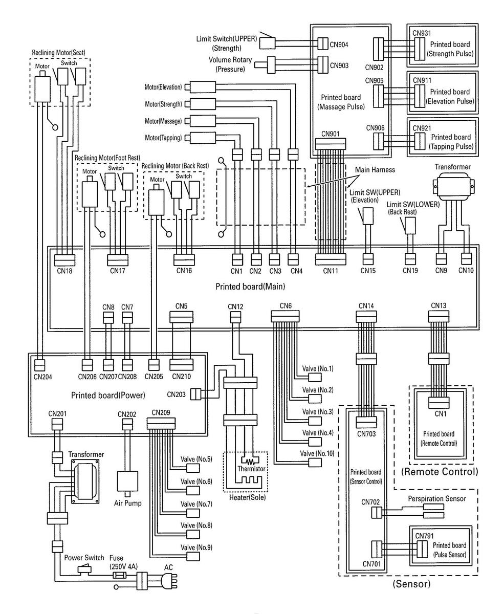
Wiring Diagram (for LOW voltage)
HEC-DR7700

- 4 --
Wiring Diagram (for HIGH voltage)
Error message indication (in Service Mode)
*Abnormal indications detected during operation are stored in a memory up to seven. Seven abnormal indications stored can be confirmed in the service mode (Older indications than the seven abnormal indications will be deleted sequentially).
To change over to the service mode, turn ON the POWER switch at the rear of the massager while simultaneously pressing the OPERATION ON/OFF on a remote controller. When the "FINE" button is pressed three times with the OPERATION ON/OFF kept pressed, the massager is placed in the service mode.
(When the massager is placed in the service mode, four blue lamps at the WHOLE BODY SENSOR AUTOMATIC COURSE come on).
POWER switch "ON" POSITION ADJUST "UP" "DOWN" button "FINE" button (three times)
To reset the service mode, turn OFF the POWER switch.
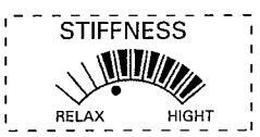
When the massager is placed in the service mode, the latest abnormal indication is displayed. The POSITION ADJUST "▼(DOWN)" button of the remote controller is used to display older abnormal indications one by one, and "▲(UP)" to display newer abnormal indication one by one (Following the sixth older (the oldest) indication, the latest indication is displayed again). Up to seven abnormal indications are stored in a memory. In case of less than seven, since there are not any abnormal indications, some of the seven STIFFNESS indicators are lit alternatively to indicate the state that abnormalities are not stored.

<Resetting Procedure of Abnormal Indication Memory>
Simultaneously press "REPATE" button on the sensor controller to delete all abnormal indication memory (When the seven STIFFNES indicators are all lit up, all abnormal indication memory have been deleted).
All abnormal indication memory have been deleted

| Troubled portion | Error message | Troubled phenomenon | Check item | Counteraction method |
| РОМЕК | Nothing is displayed after the power ON. |
|
Replace the current fuse.
Check the power switch, power cord and transformer for normal conductivity and creplace them if necessary upon check. Check the Printed board (Power). Check the Connector (Printed board). Replace the transformer. Insert the connector. Replace the Connector A,B (Remote control) of Replace the Printed board (Remote control). Replace the Printed board (Remote control) of Printed board (Main). |
|
|
REMOTE
CONTROL |
SIFFAGES |
It displays after [ remote control
communication impossible ] 3 seconds. (When Printed board (Main) detects) |
|
Insert the connector.
Insert the connector. Replace the Connector A,B (Remote control) . Replace the Printed board (Remote control) or Printed board (Main). |
| At STREAMERS |
It displays after [ remote control
communication impossible ] 3 seconds. (When Printed board (Remote control) detects) |
|
Insert the connector.
Insert the connector. Replace the Connector A,B (Remote control) . Replace the Printed board (Remote control) or Printed board (Main). |
|
| SENSER | SSBH44LS |
It displays after [ sensor
communication impossible ] 3 seconds. (When Printed board (Main) detects) |
|
Insert the connector.
Insert the connector. Replace the Connector A,B (Sensor) . Replace the Printed board (Sennsor ) or Printed board (Main). |
| 4- STEFINESS |
It displays after [ sensor
communication impossible ] 3 seconds. (When Printed board (Senser) detects) |
|
Insert the connector.
Insert the connector, Replace the Connector A,B (Sensor) . Replace the Printed board (Sennsor ) or Printed board (Main). |
|
|
Indication does not disappear.
"Grip the Sensor" |
|
Insert the connector.
dry skin), the degree of stiffness may hand cream. |
-7-
Downloaded from www.Manualslib.com manuals search engine
| Troubled portion | Error message | Troubled phenomenon | Check item | Counteraction method |
|---|---|---|---|---|
| MASSAGE | STEPHNESS | Massage mode doesn't move. |
|
Insert the connector.
Insert the connector. If output Replace the massage motor. If no output Replace the Printed board (Main). |
|
*When there is not output level
at sensor(IC902) for continuation 30 seconds while Massage motor are getting erectricity. |
A stop of massaging motion
can not be carried out. Massage motor rotation. |
|
Insert the connector.
Replace the main harness. The magnet position correction for the detection. Correct the tilted condition or replace the Printed board (Massage pulse). The massage motor belt correction, the exchange. |
|
|
STIFFACESS
MILLION MILLION MILLION |
Massage mode doesn't move. |
|
Insert the connector.
Insert the connector. If output Replace the massage motor. If no output Replace the Printed board (Main). |
|
|
*When there is no output at sensor
(IC902) for continuation 15 seconds while Massage motor are getting erectricity. |
A stop of massaging motion
can not be carried out. Massage motor rotation. |
|
Insert the connector.
Replace the main harness. The magnet position correction for the detection. Correct the tilted condition or replace the Printed board (Massage pulse). The massage motor belt correction, the exchange. |
|
| TAPPING |
STIFFACES
STIFFACES |
Tapping mode doesn't move.
A stop of tapping motion |
|
Insert the connector.
If output Replace the tapping motor. If no output Replace the Printed board (Main). Insert the connector. |
|
*When there is no output at sensor
(IC921) for continuation 15 seconds while tapping motor are getting erectricity. |
can not be carried out.
Tapping motor rotation. |
and Printed board (Massage pulse) CN901 and CN906.
2. Check turning on confirmation main harness. 3. The magnet check for the tapping detection. 4. Check the Printed board (Tapping pulse) IC921 for inclination. 1. Check the tapping motor belt for dislocation and cut-off. |
Replace the main harness.
The magnet position correction for the detection. Correct the tilted condition or replace the Printed board (Tapping pulse). The tapping motor belt correction, the exchange. |
HEC-DR7700
- 8 -
| Troubled portion | Error message | Troubled phenomenon | Check item | Counteraction method |
|---|---|---|---|---|
| STRENGTH | SERVICE CS | A stop of strength motion can not be carried out. |
|
Insert the connector. |
|
When there is no detection of lower
limit position for continuation 15 seconds while strendth motor are |
|
Replace the main harness.
The magnet position correction for the detection. Correct the tilted condition or replace the |
||
| moving downward way. | inclination. | Printed board (Strength pulse). | ||
| STHEAKESS | A stop of strength motion can not be carried out. |
|
Insert the connector. | |
| When there is no detection of upper limit | 2. The connection confirmation of Printed board (Massage | Insert the connector. | ||
|
position for continuation 15 seconds while
strength motor are moving upper ward way. |
3. Check the limit switch(strength).
4 Others. |
Replace the switch(strength).
Replace the Printed board (Main). |
||
| SILENESS | Strength mode doesn't move. | 1. The connection confirmation of Printed board (Main) CN3 | Insert the connector. | |
| And the second s |
|
If output Replace the strength motor.
If no output Replace the Printed board (Main). |
||
| • | A stop of strength motion |
|
Insert the connector. | |
| When there is not output level at | can not be carried out. |
The connection confirmation of Printed board (Strength
niles) (N931 |
||
|
sensor for continuation 15 seconds
while strength motor are getting |
|
Replace the main harness.
The magnet position correction for the |
||
|
detection.
Correct the tilted condition or replace the Printed board (Strength pulse). |
|||
| Strength motor rotation. | 1. Check the strength motor belt for dislocation and cut-off. | The strength motor belt correction, the exchange. | ||
| STIFANESS | Strength mode doesn't move. | 1. The connection confirmation of Printed board (Main) CN3 | Insert the connector. | |
| Assession Assess |
2. Check the Printed board (Main) CN3 output (approx.
DC60 - 100V). |
If output Replace the strength motor.
If no output Replace the Printed board (Main). |
||
| • | A stop of strength motion |
|
Insert the connector. | |
| _ | When there is not output level at | call not be califed out. |
The connection confirmation of Printed board (Strength
pulse) CN931. |
|
| _ | while strength motor are getting |
|
Replace the main harness.
The magnet position correction for the |
|
| 4. Check the Printed board (Strength pulse) IC931, IC932 for inclination. |
Correct the tilted condition or replace the
Printed board (Strength pulse). |
|||
| Strength motor rotation. | 1. Check the strength motor belt for dislocation and cut-off. | The strength motor belt correction, the exchange. |
| froubled portion | Error message | Troubled phenomenon | Check item | Counteraction method |
|---|---|---|---|---|
| ELEVATION |
STERNESS
STATUS Status Status Status Status Status Status Status Status Status Status Status Status Status Status Status Status Status Status Status Status Status Status Status Status Status Status Status Status Status Status Status Status Status Status Status Status Status Status Status Status Status Status Status Status Status Status Status Status Status Status Status Status Status Status Status Status Status Status Status Status Status Status Status Status Status Status Status Status Status Status Status Status Status Status Status Status Status Status Status Status Status Status Status Status Status Status Status Status Status Status Status Status Status Status Status Status Status Status Status Status Status Status Status Status Status Status Status Status Status Status Status Status Status Status Status Status Status Status Status Status Status Status Status Status Status Status Status Status Status Status Status Status Status Status Status Status Status Status Status Status Status Status Status Status Status Status Status Status Status Status Status Status Status Status Status Status Status Status Status Status Status Status Status Status Status Status Status Status Status Status Status Status Status Status Status Status Status Status Status Status Status Status Status Status Status Status Status Status Status Status Status Status Status Status Status Status Status Status Status Status Status Status Status Status Status Status Status Status Status Status Status Status Status Status Status Status Status Status Status Status Status Status Status Status Status Status Status Status Status Status Status Status Status Status Status Status Status Status Status Status Status Status Status Status Status Status Status Status Status Status Status Status Status Status Status Status Status Status Status Status Status Status Status Status Status Status Status Status Status Status Status Status Status Status Status Status Status Status Status Status Status Status Status Status Status Status Status Status Status Status |
A stop of elevation motion
can not be carried out. |
|
Insert the connector.
Replace the main harness. The magnet position correction for the detection. Correct the titled condition or replace the Printed board (Elevation pulse). |
|
When there is no detection of lower
limit position for continuation 30 seconds while elevation motor are moving downward way. |
Elevation motor rotation. |
|
insert the connector.
The elevation motor belt correction, the exchange. Insert the connector. |
|
| SSIENANATAR |
A stop of elevation motion
can not be carried out. |
|
Replace the switch assembly.
Repair limit switch (elevation) installation. Replace the switch(elevation). Replace the Printed board (Main). |
|
|
Elevation motor rotation. |
|
The elevation motor belt correction, the
exchange. Insert the connector. |
|
| States and a state of the state | Elevation mode doesn't move. |
|
Insert the connector.
If output Replace the elevation motor. If no output Replace the Printed baard (Main). The elevation motor belt correction, the exchange. |
|
|
When there is not output level at
sensor(IC912) for continuation 30 seconds while elevation motor are getting erectricity. |
A stop of elevation motion
can not be carried out. |
|
Insert the connector.
Replace the main harness. The magnet position correction for the detection. Correct the tilted condition or replace the Printed board (Elevation pulse). Replace the switch(elevation). Insert the connector. |
|
|
STIFFICES
SIFFICES |
Elevation mode doesn't move. |
|
Insert the connector.
If output Replace the elevation motor. If no output Replace the Printed board (Main). The elevation motor belt correction, the exchange. |
|
|
When there is not output level at
sensor(IC911) for continuation 30 seconds while elevation motor are getting erectricity. |
A stop of elevation motion
can not be carried out. |
|
Insert the connector.
Replace the main harness. The magnet position correction for the detection. Correct the tilted condition or replace the Printed board (Elevation pulse). |
Downloaded from www.Manualslib.com manuals search engine
| Troubled portion | Error message | Troubled phenomenon | Check item | Counteraction method |
|---|---|---|---|---|
|
RECLINING
FOOT REST |
STEPHCES
MILLION MILLION MERCENTRAL |
The foot rest reclining motion
doesn't move. (Don't up) |
|
Insert the connector.
If output Replace the reclining motor (foot rest). If no output Replace the Printed board (Power). |
|
When there is no detection of rectining
switch(upper limit) at the foot part for continuation 1 minutes while reclining motor are moving for raising seat. |
A foot rest lilacinning operation
stop is not carried out. |
|
Insert the connector.
Replace the reclining motor (foot rest). Replace the Printed board (Main). |
|
|
STRENESS
MILLION MILLION MILLION |
The foot rest reclining motion
doesn't move. (Don't down) |
|
Insert the connector.
If output Replace the reclining motor (foot rest). If no output Replace the Printed board (Power). |
|
|
When there is no detection of reclining
switch(lower limit) at the foot part for continuation 1 minutes while reclining motor are moving for lower seat. |
A foot rest lilacinning operation stop is not carried out. |
|
Insert the connector.
Replace the reclining motor (foot rest). Replace the Printed board (Main). |
|
|
STIFFNESS
STIFFNESS Packar Maan |
The foot rest reclining motion
doesn't move. (Don't down) |
|
Insert the connector.
If output Replace the reclining motor (foot rest). If no output Replace the Printed board (Power). |
|
|
When there is detection of reclining
switch(upper limit) at the foot part for continuation 1 minutes while reclining motor are moving for lower seat. |
A foot rest lilacinning operation
stop is not carried out. |
|
Insert the connector.
Replace the reclining motor (foot rest). Replace the Printed board (Main). |
|
| STREMESS |
The foot rest reclining motion
doesn't move. (Don't up) |
|
Insert the connector.
If output Replace the reclining motor (foot rest). If no output Replace the Printed board (Power). |
|
|
When there is detection of reclining
switch(lower limit) at the foot part for continuation 1 minutes while reclining motor are moving for raising seat. |
A foot rest lilacinning operation
stop is not carried out. |
|
Insert the connector.
Replace the reclining motor (foot rest). Replace the Printed board (Main). |
- 11 -
| Counteraction method |
Insert the connector.
If output Replace the reclining motor (back rest). If no output Replace the Printed board (Power). |
Insert the connector.
Replace the reclining motor (back rest). Replace the Printed board (Main). |
Insert the connector.
If output Replace the reclining motor (back rest). If no output Replace the Printed board (Power). |
Insert the connector.
Replace the reclining motor (back rest). Replace the Printed board (Main). |
Insert the connector.
If output Replace the reclining motor (back rest). If no output Replace the Printed board {Power}. |
Insert the connector.
Replace the reclining motor (back rest). Replace the Printed board (Main). |
Insert the connector.
If output Replace the reclining motor (back rest). If no output Replace the Printed board (Power). |
Insert the connector.
Replace the reclining motor (back rest). Replace the Printed board (Main). |
|---|---|---|---|---|---|---|---|---|
| Check item |
|
|
|
|
|
|
|
|
| Troubled phenomenon |
The back rest reclining motion
doesn't move. (Don't up) |
A back rest lilacinning operation
stop is not carried out. |
The back rest reclining motion
doesn't move. (Don't down) |
A back rest lilacinning operation
stop is not carried out. |
The back rest reclining motion
doesn't move. (Don't down) |
A back rest lilacinning operation stop is not carried out. |
The back rest reclining motion
doesn't move. (Don't up) |
A back rest lilacinning operation stop is not carried out. |
| Error message |
STIFFNESS
MULTIC |
When there is no detection of reclining
switch(upper limit) at the back part for continuation 1 minutes while reclining motor are moving for raising seat. |
STEFICES
AND MARKEN |
When there is no detection of reclining
switch(lower limit) at the back part for continuation 1 minutes while reclining motor are moving for lower seat. |
SCHERNESS |
When there is detection of reclining
switch(upper limit) at the back part for continuation 1 minutes while reclining motor are moving for lower seat. |
STEPRESS
MULTIN ACTION |
When there is detection of reclining
switch(lower limit) at the back part for continuation 1 minutes while reclining motor are moving for raising seat. |
| Troubled portion |
RECLINING
BACK REST |
L |
| Froubled portion | Error message | Troubled phenomenon | Check item | Counteraction method |
|---|---|---|---|---|
|
RECLINING
SEAT |
SETENCES A |
The seat reclining motion
doesn't move. (Don't down) |
|
Insert the connector.
If output Replace the reclining motor (seat). If no output Replace the Printed board (Power). |
|
When there is no detection of reclining
switch(lower limit) at the seat part for continuation 1 minutes while reclining motor are moving for lower seat. |
A foot rest lilacinning operation
stop is not carried out. |
|
Insert the connector.
Replace the reclining motor (seat). Replace the Printed board (Main). |
|
|
STRATESS
STRATESS North Manual |
The foot rest reclining motion
doesn't move. (Don't up) |
|
Insert the connector.
If output Replace the reclining motor (seat). If no output Replace the Printed board (Power). |
|
|
When there is no detection of reclining
switch(upper limit) at the seat part for continuation 1 minutes while reclining motor are moving for raising seat. |
A foot rest lilacinning operation
stop is not carried out. |
|
Insert the connector.
Replace the reclining motor (seat). Replace the Printed board (Main). |
|
| НЕАТЕК |
STEPHCESS
MULLIC RELAX |
When there is thermistor output
of continuation 2 second and more then 4.9V. |
|
Insert the connector.
Replace the Connector ass'y A,B (heater). Replace the heater(sole). Replace the Printed board (main). |
|
STITUTES
STITUTES States States States States States States States States States States States States States States States States States States States States States States States States States States States States States States States States States States States States States States States States States States States States States States States States States States States States States States States States States States States States States States States States States States States States States States States States States States States States States States States States States States States States States States States States States States States States States States States States States States States States States States States States States States States States States States States States States States States States States States States States States States States States States States States States States States States States States States States States States States States States States States States States States States States States States States States States States States States States States States States States States States States States States States States States States States States States States States States States States States States States States States States States States States States States States States States States States States States States States States States States States States States States States States States States States States States States States States States States States States States States States States States States States States States States States States States States States States States States States States States States States States States States States States States States States States States States States States States States States States States States States States States States States States States States States States States States States States States States States States States States States States States States States States States States States State |
When there is thermistor output
of continuation 2 second and less then 0.1V. |
|
Insert the connector.
Replace the Connector ass'y A,B (heater). Replace the heater(sole). Replace the Printed board (main). |
|
|
PRESSURE
SENSOR |
STEFACES
N.E.M. HELM |
When there is pressure sensor
output of Continuation 3 second and less then 0.1V. |
|
Replace the volume rotary (pressure).
Insert the connector. Replace the main harness. Replace the Printed board (main). |

HEC-DR7700
– 14 – -
HEC-DR7700
Air-Bag Operation Confirmation Procedure
Start-up of Examination Mode
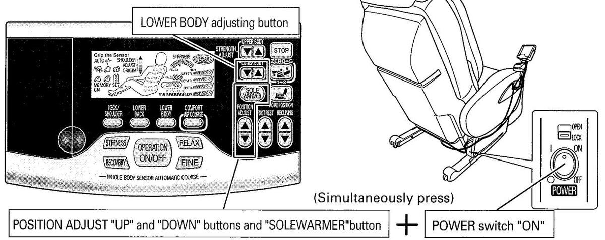
Turn ON the POWER switch at the rear of the massager while simultaneously pressing the POSITION ADJUST "UP" and "DOWN" buttons and "SOLE WARMER" button on the remote controller (This operation should be started with the POWER switch turned OFF). When the examination mode is started up, both a backrest and a foot rest move slightly and come to a stop.
Air-Bag Operation Confirmation
Press either "▼(DOWN)" or "▲(UP)" button of the LOWER BODY adjustment on the remote controller.
Check if the air-bag inflates sequentially as shown below.
* If there are any problems, check air leakage, breakage of air hoses, and the air-bag.

1, Foot pinching, outside 2, Foot pinching, inside 3, Foot shiatsu, middle 4. Foot shiatsu, back and forth 5, Ankle pinching 6, Leg pinching, inside, outside 7, Leg shiatsu, lower 8, Leg shiatsu, upper 9. Waist, right, left
Motor Operation Confirmation Procedure
HEC-DR7700
Start-up of Examination Mode
Turn ON the POWER switch at the rear of the massager while simultaneously pressing the POSITION ADJUST "UP" and "DOWN" buttons and "SOLE WARMER" button on the remote controller (This operation should be started with the POWER switch turned OFF). When the examination mode is started up, both a backrest and a foot rest move slightly and come to a stop.
Air-Bag Operation Confirmation
Press either "V(DOWN)" or "A (UP)" button of the LOWER BODY adjustment on the remote controller. (move for 3min)
Motor Operation Confirmation
Seven motors work at the same time when they push "REPEAT" button.
Massage motor and tapping motor is fastest moves.
Elevevation motor and Strength motor goes to an upper
point and lower point and return.
Reclinning motor (foot rest/back rest/seat) repeats the expansion and contraction.
Movement / a stop is possible with a "REPEAT" button again and again.
*When I changed massage unit assembly / reclining motore /pcb, I confirm movement by this function.
Because lstop by an error when there is abnormality, I confirm a place of pertinence. As for this function , sole warmer / air pump / valve moves at the same time ,too.
<Back rest>

<Seat under>


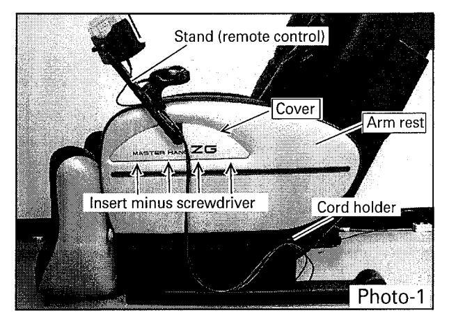
(1) Replacement of arm rest assembly , cover (arm rest lower)
- 1, Remove one cord holder set screw and unfix two remote controller cords. Photo-1
- 2, Insert a minus screwdriver in a hole under a cover and remove a this side discounted cover. Photo-1
- 3, Remove three stand assembly (remote control) set screws and take off the stand assembly (remote control). Photo-2
- 4, Remove two set screws on the arm rest and lift up and take off the arm rest . Photo-2
- 5, Take off the other side in the same way.
- 6, Remove four cover (arm rest lower) set screws and take off the cover (arm rest lower). Photo-2

- (2) Replacement of PCBs (main) & (power)
- 1, Remove four cover (arm rest lower) left set screws and take off the cover (arm rest lower) left. Photo-2
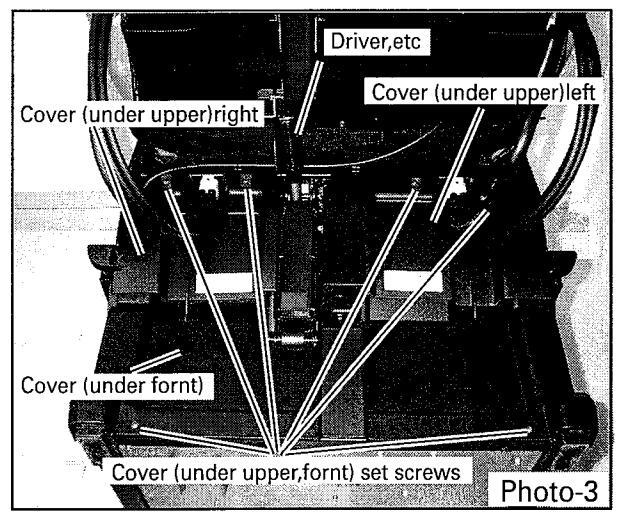
- 2, Defeat the main body so that a leg becomes the top with the back possible Photo-3
- 3, Lift up a foot rest and insert a screwdriver and so forth into a link to fix the link.
Photo-3
4, Remove six cover (under) set screws and take off the cover (under upper)right ,cover (under upper)left, cover (under front)
Photo-3
5, Remove one cover (PCB) set screws and take off the latches of ribs at the rear of the cover (PCB). Photo-4

HEC-DR7700
- 6, Disconnect connectors connected to the PCB (power). Photo-5
- 7, Unfix nine stoppers (PCB) and take off the PCB (power). Photo-5
- 8, Remove three stay (PCB) set screws and take off the stay (PCB). Photo-5
- * There is a set screw around under a reclining motor at the left side.
- 9, Disconnect the connectors connected to the PCB (main). Photo-5
- 10, Unfix nine stoppers (PCB) from the bottom side of the massager and take off the PCB (main). Photo-5

(3) Replacement of Valve
- 1, Take off the arm rest and cover(arm rest lower). Photo-1,2
- 2, Take off the cover (under front ) Photo-3
- 3, Disconnect each air hose. Photo-6
*When taking off the air hoses, indicate a mark such as number, symbol (Exercise care so as not to make a mistake in connecting the hoses).
- 4, Remove the cord processing of a valve. Photo-6
- 5, Remove one holder(valve) set screws and take off the valve assembly and holder(valve).
- 6, Remove two valve set screws and take off the valve assembly. Photo-6

(4) Replacement of Air Pump, Transformer
- 1, Take off the arm rest and cover(arm rest lower). Photo-1,2
- 2, Take off the cover (under front ) Photo-3
- 3 , Remove two cover(air pump) set screws and take off the cover(air pump). Photo-7
- 4, Take off the cord processing of an air pump.
- 5, Remove four fixing rubbers of the air pump and take off the air pump. Photo-7
- 6, Take off the cord processing of a transformer.
- 7, Remove two transformer set screws and take off the transformer. Photo-7

HEC-DR7700
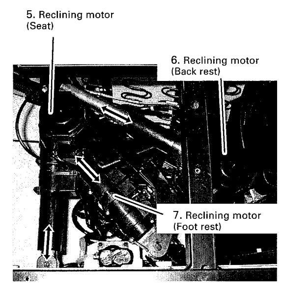
(5) Replacement of Reclining Motor
- 1, Take off the arm rest and cover(arm rest lower). Photo-1,2
- 2, Take off the cover (under front ). Photo-3
- 3, Disconnect each cord processing and cords.
- 4, Lay down the massager with its left side facing downward. Photo-8

5, Each reclining motor (set) is fixed at two places on both ends. Therefore, remove E rings on both ends and pull out fixing pins. Photo-9

- (6) Replacement of Power Switch and Current Fuse
- 1, Take off the cover (arm rest lower) right. Photo-2
- 2, Remove each cord processing and disconnect the cords.
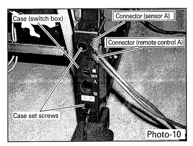
- 3, Remove two case (switch box) set screws and take off the case (switch box).
Photo-10
- 4, Open a fuse case of current fuses and take out a current fuse. Photo-11
- 5, Remove two switch holder set screws and take off a switch holder.
Photo-11
6, Remove a switch fixing screw and take off the POWER switch. Photo-11

- 19 - -
HEC-DB7700
Replacement Procedure
(7) Replacement of Remote Control
- 1. Take off the cover (arm rest lower) right. Photo-2
- 2. Take off the power supply box assembly. , Photo-10
- 3. Remove each connector processing and disconnect the connectors. Photo-12

4. Remove nine remote control case set screws and take off a remote control case (lower). Photo-13

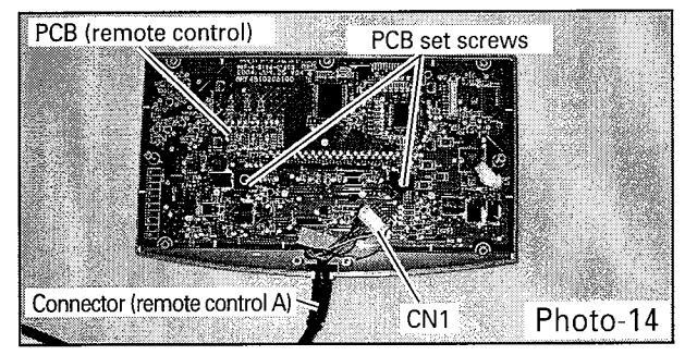
5, Remove two PCB (remote control) set screws and take off the PCB (remote control).
Photo-14
6. Disconnect the interconnecting connector CN1 of the connector (remote control A).
Photo-14
(8) Replacement of Sensor
1. Take off the cover (arm rest lower) right. Photo-2
- 2. Take off the power supply box assembly. Photo-10
- 3, Remove each cord processing and disconnect the cords. Photo-12
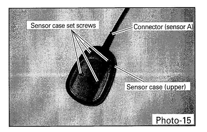
- 4. Remove four sensor case set screws and take off the sensor case (upper).
Photo-15
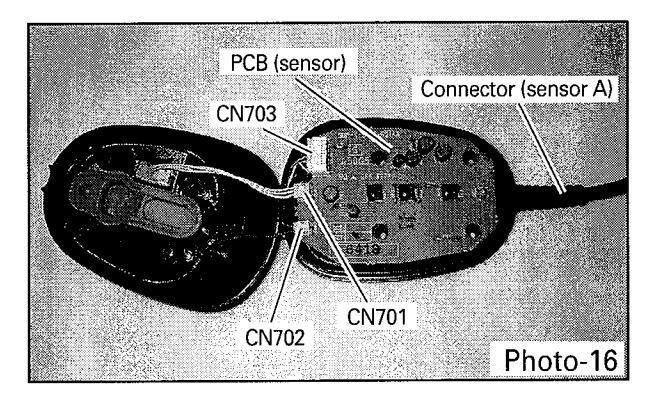
5. Take off the PCB (sensor). Photo-16 6. Disconnect the interconnecting connector CN701 .CN702.CN703 of the connector (sensor A).
Photo-16
HEC-DR7700
(9) How to Remove A Massage Unit
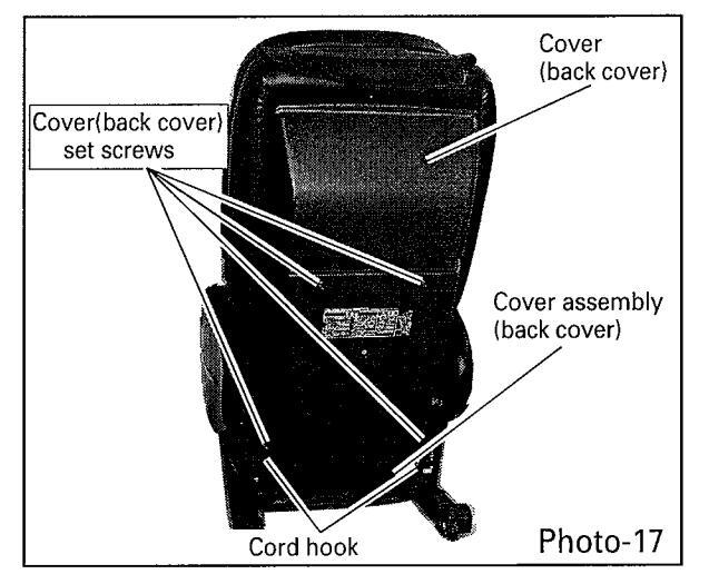
- 1, Cut off four fixed bands tying cover assembly (back cover) and cord hook to. Photo-17
- 2, Remove four cover(back cover) set screws and take off a cover(back cover). Photo-17
3, Move the massage unit upwards to its top position. Usually the massage unit is at a stop at its top position. When the massage unit is at a stop halfway, however, turn on the power and make the massage unit move up to its top position. At the top position, when the massage unit comes to a stop, pull out a POWER plug.

* While the massage unit is moving upwards, exercise care so as not to come into contact with the operating portion.
If the massage unit does not move upwards when the power is turned on, turn a pulley (elevation) clockwise to move the massage unit to the top position. Photo-18
-
Remove the cord processing of the cord (main) and disconnect the connectors (four connectors for motors, one for signal line). Photo-19 Remove one earthing set screw and cut eight insulation lock black cords.
- * Cut the cords with a nipper so that the cords do not get scratched.
- * In order to restore the wiring processing after reassembling the massage unit, indicate a markon the cords before disconnecting the wiring.
- 5, Remove one spring A (harness main) set screw and take off a spring A (harness main). Photo-19
- 6, Remove two screws(stopper) inside of a back frame. Photo-19
- 7, Turn the pulley (massage) clockwise to minimize the massage hand width.
Photo-19
8, Turn the pulley (strength) counterclockwise to bring to minimum position (maximum strength) of a thread bar. Photo-19

HEC-DR7700
9, Turn the pulley (evevation) clockwise, move the massage unit upwards, and take off a driving wheel from a back frame guide.
Photo-20
* When taking off the driving wheel, hold the massage unit firmly.

10, With a guide roller removed, further turn the pulley (evevation) clockwise.
Photo-21
11, When right and left gears are disengaged from the back frame gears (rack), take off the massage unit from the massager body. Photo-21

(10) How to Reassemble the Massage Unit
-
1, Tape a lever of a micro switch.
- For the purpose of preventing the lever of the micro switch from being deformed or damaged by incidentally hitting it when installing the massage unit.
- * After installing the massage unit, peel the tape. Photo-22

2, Before fitting the massage unit into the massager body, minimize massage hand width by turning the pulley (massage) clockwise.
Turn the pulley (strength) counterclockwise to bring to minimum position (maximum strength) of a thread bar. Photo-23

3, Fit the massage unit in parallel so that the first right and left gear (rack) teeth engage with the right and left gears of the massage unit simultaneously. Photo-23
HEC-DR7700
- (11) Replacement of PCB (strength pulse)
- 1, Disconnect the connector CN931 of the PCB (strength pulse). Photo-24
- 2, Remove one PCB (strength pulse) set screw and take off the PCB (strength pulse).
Photo-24

- (12) Replacement of Motor (strength)
- 1, Remove each cord processing.
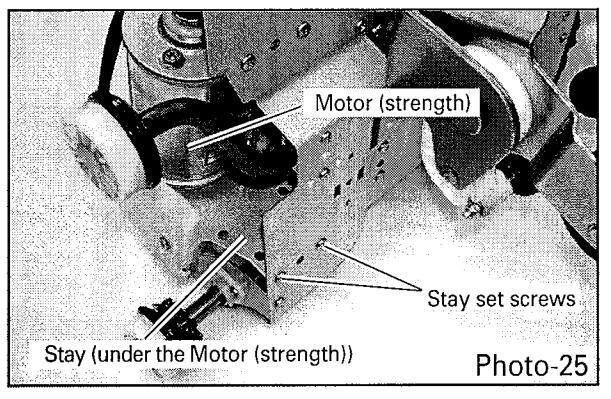
- 2, Remove two stay (under the motor (strength)) set screws. Photo-25
- 3, Disconnect the belt (strength). Photo-24
- 4, Remove two motor (strength) set screws and take off the motor (strength) and the stay (under the motor (strength)). Photo-24, 25
-
5, Remove two motor (strength) set screws and take off the motor (strength).
- * Exercise care so as not to adhere grease to the driving portions such as belt
(Failure to observe this precaution may lead to malfunction due to slippage).
- (13) Replacement of PCB (Massage)
- 1, Disconnect five PCB (massage) connectors. Photo-26
- 2, Remove two PCB (massage) set screws and take off the PCB (massage). Photo-26

- (14) Replacement of Motor (Massage)
- 1, Remove each cord processing.
- 2, Disconnect the belt (massage). Photo-26
3, Remove two motor (massage) set screws. Photo-26
Photo-26
- 4, Remove two stay (under the motor (massage)) set screws and take off the motor (massage). and the stay (under the motor (massage)). Photo-27
-
5, Remove one motor (massage) set screw and take off the motor (massage). Photo-27
- * Exercise care so as not to adhere grease to the driving portions such as belt (Failure to observe this precaution may lead to malfunction due to slippage).

HEC-DR7700
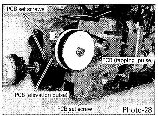
- (15) Replacement of PCB (Tapping pulse) and PCB(elvation pulse)
- 1, Disconnect the connector CN921 of the PCB (tapping pulse). Photo-28
- 2, Remove one PCB (tapping pulse) set screw and take off the PCB (tapping pulse).
Photo-28
- 3, Disconnect the connector CN911 of the PCB (elevation pulse). Photo-28
- 4, Remove two PCB (elevation pulse) set screws and take off the PCB (elevation pulse).
Photo-28
- (16) Replacement of Motor (elevation)
- * Take off the motor (massage) in advance.
- 1, Remove each cord processing.
2, Remove two stay motor (elevation) set screws. Photo-29
3, Remove two motor (elevation) set screws.


4, Disconnect the belt (elevation).
Photo-30
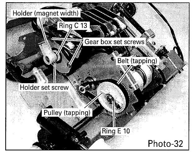
5, Remove two gear box (elevation) set screws, slide the gear box outwards, and turn it clockwise as shown in Photo-32.
Photo-30, 31
6, Remove two stay motor (elevation) set screws. Photo-30

7, Remove two motor (elevation) set screws and take off the motor (elevation).
Photo-31
* Exercise care so as not to adhere grease to the driving portions such as belt (Failure to observe this precaution may lead to malfunction due to slippage).

HEC-DR7700
(17) Replacement of Motor (Tapping)
- * Take off the motor (massage) and motor (elevation) in advance.
- 1, Disconnect the belt (tapping). Photo-32
- 2, Remove ring E 10 and pull out pulley (tapping) from shaft. Photo-32
- 3, Remove one holder (magnet width) set screw and pull out holder (magnet width) from shaft. Photo-32
- 4, Remove ring C 13 from shaft. Photo-32
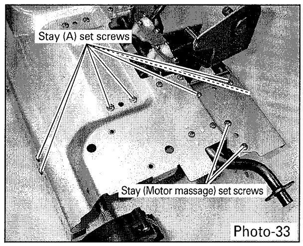
- 5, Remove two stay (motor massage) set screws. Photo-33
- 6, Remove seven stay (A) set screws.
Photo-33
7, Remove two holder (shaft tapping) set
| serews. | Photo-34 |
|---|---|
| 8, Remove ring E 10. | Photo-34 |
9, Remove two motor (tapping) set screws.
Photo-34

10, Move stay (A) along a shaft.Photo-3511, Take out the moter (tapping).Photo-35
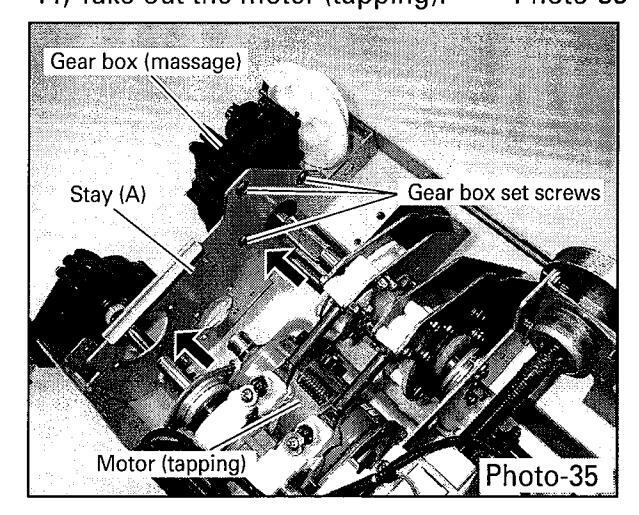
- (18) Replacement of Gear box (Massage)
- 1, Remove two gear box (massage) set screws. Photo-32
- 2, Remove three gear box (massage) set screws and pull out gear box (massage) from shaft. Photo-35
HEC-DR7700
(19) Replacement of Limit switch (Elevation)
1, Remove one cover (shaft screw) set screw and take off the cover (shaft screw).
Photo-36
2, Take off the holder (limit switch).
Photo-36
3, Disconnect the limit switch.
Photo-36

(20) Replacement of Volume rotary
- * Take off the motor (strength) in advance.
- 1, Remove one cam (pressure) set screw and take off the cam (pressure).
Photo-37
- 2, Loosen a nut of volume fixation and take off the volume rotary. Photo-37 3. Disconnect the volume rotary.
- 3, Disconnect the volume rotary.
Photo-37

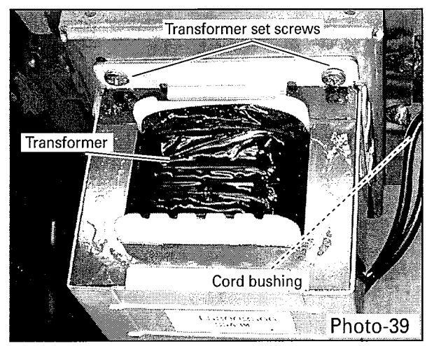
- (21) Replacement of Transfommer
- 1, Disconnect the transformer connector.
Photo-38
- 2, Remove one cover (transformer) set screw and cut of two fixed bands.
- 3, Take off the cover (transformer).
Photo-38

4, Remove two transformer set serews. Photo-39
| - | n | In the first second | DI 00 | |
|---|---|---|---|---|
| э, | Remove | cora | busning. | Photo-39 |
HEC-DR7700
(22) Replacement of Foot rest comp.
- 1, Defeat the main body so that a leg becomes the top with the back possible. Photo-40
- 2, Lift up a foot rest and insert a screwdriver and so forth into a link to fix the link.
Photo-40
3 , Remove six cover (under) set screws and take off the cover (under upper)right ,cover (under upper)left, cover (under front).

4, Disconnect each air hose and disconnect connector assembly (HEATER B). Photo-41

5, Remove four stand piece set screws and take off the stand piece.
Photo-42

6, Remove four cover (leg upper) set screws and take off the cover (leg upper) right , cover (leg upper) left. Photo-43

HEC-DR7700
7, Remove five cover (leg lower) set screws and take off the cover (leg lower) right , cover (leg lower) left. Photo-44

- 8, Remove six foot rest comp set screws and take off the foot rest comp.
- * Set screw four them hide behind helicalc spring of right and left. Photo-45

5, Open a fastener of foot rest cover and unite cover fixation string and take off the foot rest cover.
Photo-46
6, Exchange of air hose and air bag is possible. Photo-46


SANYO Electric Co.,Ltd Osaka, Japan
Apr./2007 Printed in Japan


 Loading...