

sanyo HDR-SR11, HDR-SR11E, HDR-SR12, HDR-SR12E Diagram
HDR-SR11/SR11E/SR12/SR12E
RMT-835
Ver. 1.2 2008.06
Revision History
Revision History
Link
Link
Before starting adjustments
Adjusting items when replacing main parts and boards
List of service tools
CAMERA SECTION ADJUSTMENTS
PREPARATIONS BEFORE ADJUSTMENTS
ADJUSTMENT PROGRAM
HDD SYSTEM ADJUSTMENTS
DESTINATION DATA WRITE
SECTION 6
ADJUSTMENTS
SERVICE MODE
APPLICATION FOR ADJUSTMENT (SeusEX)
SERVICE MODE
DATA BACKUP
Auto-ADJ
USB SERIAL No. INPUT
VIDEO SYSTEM ADJUSTMENTS
CAMERA SYSTEM ADJUSTMENTS
LCD/EVF SYSTEM ADJUSTMENTS
AUDIO SYSTEM ADJUSTMENTS
ERROR
• Use this Service Manual together with the Automatic Adjustment Program (HDR-SR11 Series Auto-Adj
Ver_1.2r03.exe).
HDR-SR11/SR11E/SR12/SR12E_ADJ
9-852-254-53
Sony EMCS Co.
2008F0500-1
© 2008.6
Published by Kohda TEC
6. ADJUSTMENTS
p
j
j
p
j
j
j
j
j
d
Before starting adjustments
1-1. Adjusting items when replacing main parts and boards
When replacing main parts and boards, adjust the items indicated by z in the following table.
Note 1: The Automatic Adjustment Program does not support.
Note 2: When replacing the HDD block, refer to “HDD Replacement Procedure”. (See page 6-10)
Note 3: IC2101 (Flash memory) on the VC-516 board cannot be replaced.
Replaced parts
Parts replacementBlock replacement
Board
replacement
Adjusting item
Destination Data
Write
USB Serial No.
ut
In
(Note 1)
S VIDEO OUT an
VIDEO OUT
adjustment
COMPONENT
OUT adjustment
CAMERA
adjustment 1
CAMERA
ad
ustment 2
CAMERA
ad
ustment 3
CAMERA
adjustment 4
CAMERA
adjustment 5
CAMERA
adjustment 6
CAMERA
ad
ustment 7
CAMERA
ad
ustment 8
LCD
adjustment
EVF
adjustment
Touch panel
ad
ustment
AUDIO adjustment Internal 3ch microphone sensitivity adj.
Adjustment
Destination data write
USB serial No. input
Origin oscillation check
S VIDEO OUT Y level adj.
S VIDEO OUT chroma level adj.
VIDEO OUT level check
COMPONENT OUT Y level adj.
COMPONENT OUT Pb level adj.
COMPONENT OUT Pr level adj.
STEADY HALL adj.
HALL & MR adj.
Flange back adj.
Flange back check
F No. & ND light qualiy
standard data in
Mechanical shutter ad
Linear matrix adj.
AWB standard data input
LV standard data input
AWB adj.
Color reproduction adj. & check
MAX GAIN adj.
White defect adj.
Black defect adj.
Strobe light level & white balance adj.
GYRO sensor sensitivity adj.
V-COM adj.
Transmissive mode white balance ad
EVF automatic adj.
White balance adj.
Touch panel adj.
ut
Lens device
HDD block (Note 2)
LCD block LCD901 (LCD panel)
EVF block LCD902 (LCD panel)
Flash unit
Microphone unit MIC901
CMOS block assy (Including CM-094 board and CMOS imager)
BL-017 board D5701 (EVF backlight)
FR-278 board SE9001, 9002 (PITCH, YAW sensor)
VC-516 board X1301 (Clock generator)
VC-516 board IC2401 (D/A conv.)
VC-516 board IC2501 (Component out AMP)
VC-516 board IC2801 (Video out, Audio I/O)
VC-516 board IC3101 (EVF drive)
PD-343 board IC5901 (LCD drive)
BL-017 board (COMPLETE)
FR-278 board (COMPLETE)
VC-516 board (COMPLETE)
PD-343 board (COMPLETE)
z
z
zz
zzz
zz
z
zz z
zz z
z
z
zz
zzzz
.
zzzzz
z
z
z
z
z
zzzzz
zzz
z
z
z
z
z
z
HDR-SR11/SR11E/SR12/SR12E_ADJ
Table 6-1-1
6-1
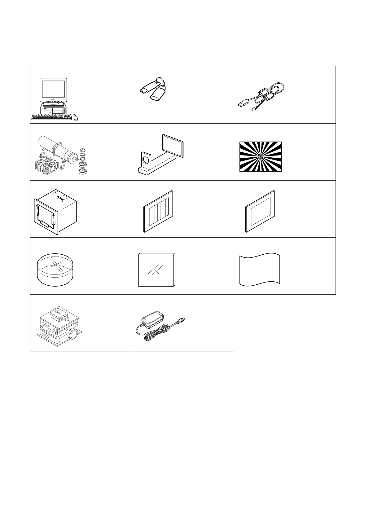
1-2. List of service tools
• Oscilloscope • Color monitor • Frequency counter
• Amplifier built-in speaker for PC • Adjustment sound source file
J-1
J-4
J-7
J-10
Personal computer
(Note)
Minipattern box
J-6082-353-B
Pattern box PTB-450
J-6082-200-A
or
Small pattern box
PTB-1450
J-6082-557-A
Filter for color
temperature correction
(C14)
J-6080-058-A
J-2
HASP key and application
for adjustment (SeusEX)
Contact our service headquater of each area
how to get the application for adjustment
(SeusEX) and HASP key.
J-5
Flange back
adjustment jig
J-6082-563-A
J-8
Color bar chart
For PTB-450:
J-6020-250-A
For PTB-1450:
J-6082-559-A
J-11
ND filter 1.0
J-6080-808-A
ND filter 0.4
J-6080-806-A
ND filter 0.1
J-6080-807-A
J-3
USB cable
1-829-868-31
J-6
Siemens star chart
J-6080-875-A
J-9
Clear chart
For PTB-450:
J-6080-621-A
For PTB-1450:
J-6082-560-A
J-12
Background paper
J-2501-130-A
J-13
Camera table
J-6082-384-A
Note: Personal computer
OS: Windows 2000/XP Home/XP Pro
RAM: 256MB or more recommended
USB: 2.0 recommended (also compatible with 1.1)
Two connectors are required.
J-14
AC adaptor
AC-L200/L200B
1-479-285-21
Fig. 6-1-1
HDR-SR11/SR11E/SR12/SR12E_ADJ
6-2
Ver. 1.2 2008.06
6-1. CAMERA SECTION ADJUSTMENTS
1-1. PREPARATIONS BEFORE ADJUSTMENTS
(CAMERA SECTION)
1-1-1. Preparations
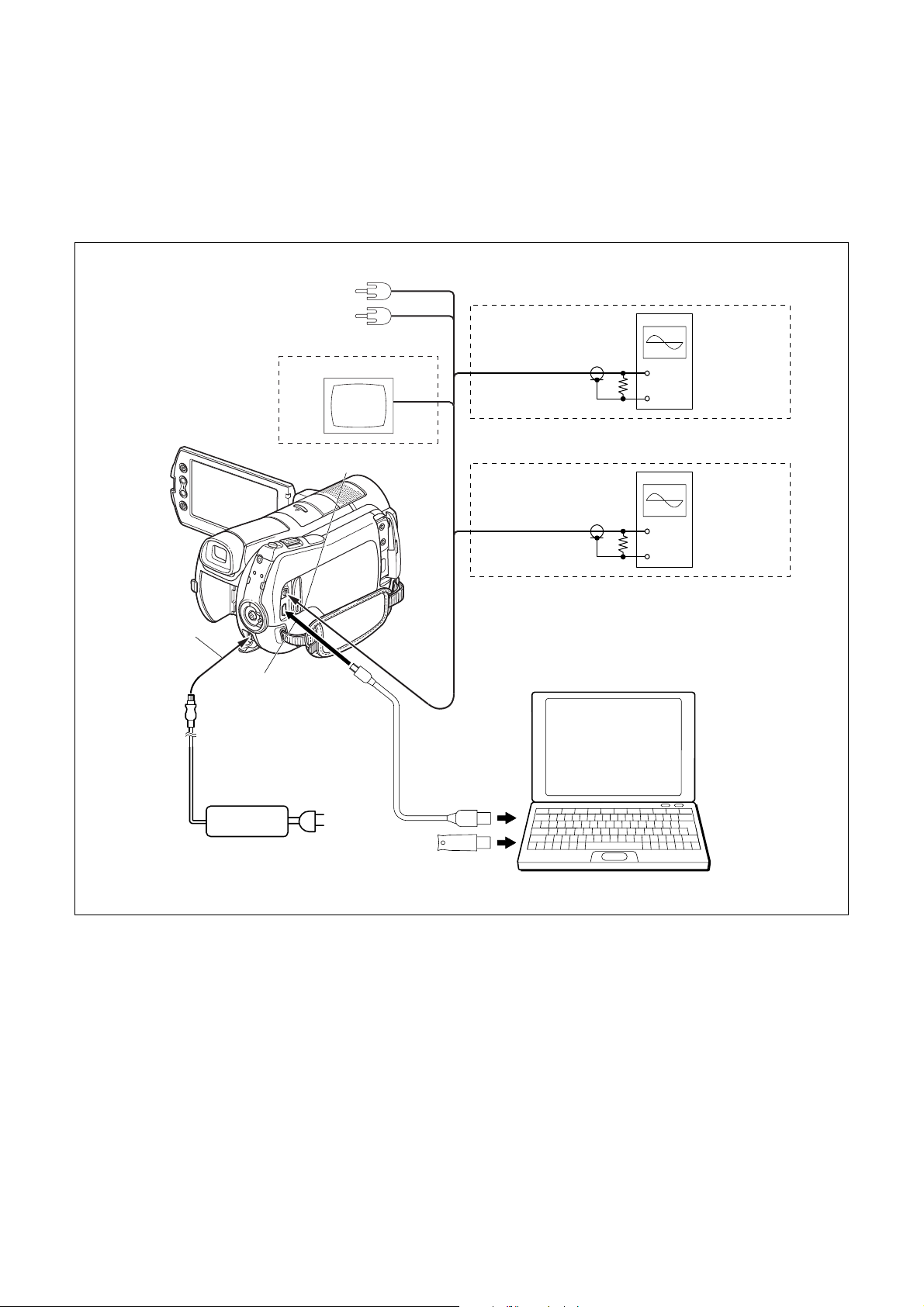
1) Connect the equipment for adjustments according to Fig. 6-1-2.
To DC IN jack
Camera system Adjustment
Color monitor
To A/V Remote connector
To USB jack
Audio L
Audio R
Video
S VIDEO OUT and VIDEO OUT Adjustment
Oscilloscope
S-Video or
Video
COMPONENT OUT Adjustment
Y or Pb or Pr
PC
OS: Windows 2000/XP
RAM: 256MB or more recommended
USB: 2.0 recommended (also compatible with 1.1)
Two connectors are required.
Terminated
75 Ω
Oscilloscope
Terminated
75 Ω
(The SeusEX must be installed in the PC.)
AC adaptor
AC-L200/L200B
(1-479-285-21)
USB cable
(1-829-868-31)
AC IN
HASP Key
Fig. 6-1-2
HDR-SR11/SR11E/SR12/SR12E_ADJ
6-3
1-1-2. Precaution
1. Setting the Switch
Unless otherwise specified, set the switches as follows and perform adjustments without inserting disc.
1. POWER switch ............................................................. Movie
2. BACK LIGHT .................................................................. OFF
3. NIGHT SHOT .................................................................. OFF
4. (OPTION) menu
FOCUS .......................................................................... AUTO
2. Order of Adjustments
Basically carry out adjustments in the order given.
Color bar chart (Color reproduction adjustment frame)
H
Yellow
Cyan
Green
AB B
Fig. a
(VIDEO terminal of A/V jack
output waveform)
A=B
White
Magenta
Red
CD
Blue
A
Enlargement
B
C = D = 0
Difference in level
A
5. (HOME) menu – (SETTINGS) – MOVIE SETTINGS
DIGITAL ZOOM ............................................................. OFF
STEADY SHOT ............................................................... OFF
6. (HOME) menu – (SETTINGS) – GENERAL SET
DEMO MODE ................................................................. OFF
Electronic beam scanning frame
White
Red
Magenta
Cyan
Green
Yellow
V
Fig. b (monitor TV picture)
Adjust the camera zoom and direction to
obtain the output waveform shown in Fig. a and
the monitor TV display shown in Fig. b.
CRT picture frame
Blue
Fig. 6-1-3
3. Subjects
1) Color bar chart (Color reproduction adjustment frame)
When performing adjustments using the color bar chart, adjust the picture frame as shown in Fig. 6-1-3. (Color reproduction adjustment frame)
2) Clear chart (AWB adjustment frame)
Shoot the color bar chart. Then adjust the zoom to TELE side
from WIDE side, and stop it when the black frame of the chart
disappears. Remove the color bar chart from pattern box and
insert a clear chart in its place.
3) Chart for flange back adjustment
Join together a piece of white A0 size paper (1189 mm × 841
mm) and a piece of black paper to make the chart shown in
Fig. 6-1-4.
Note: Use a non-reflecting and non-glazing vellum paper. The
size must be A0 or larger and the joint between the white
and black paper must not have any undulations.
White
841 mm
Black
1189 mm
Fig. 6-1-4
HDR-SR11/SR11E/SR12/SR12E_ADJ
6-4
Ver. 1.2 2008.06
4. Setting Distance between Pattern Box and Camera
Set the distance from the front of the lens to the pattern box as
shown in Fig. 6-1-5.
L = 1 m (PTB-450)
L = 40 cm (PTB-1450)
Pattern box
Front of the lens
L
Camera
Fig. 6-1-5
5. Precautions When Using Pattern Box
1) It takes about 30 minutes for pattern box to stabilize its brightness.
Turn on the pattern box 30 minutes before the adjustment starts.
2) Make arrangement so that the outside light does not enter the chart surface in the pattern box.
Also, place a board between chart and camera, and make a hole at the lens part of the board so that the camera is not reflected in the
shot image screen.
(Adjustment may not be performed correctly due to the influence of outside light.)
Example 1: Place a box to block a section between pattern box and camera.
Make the hole of the same
size as the pattern box.
Pattern box
L = 1 m (PTB-450)
L = 40 cm (PTB-1450)
L
Make the hole of the same
size as the lens.
Front of the lens
Camera
Example 2: Place a board having a hole in front of the camera and cover the pattern box and camera with a blackout curtain
Cover with a blackout curtain
L = 1 m (PTB-450)
Pattern box
L = 40 cm (PTB-1450)
L
Board that opens hole
to lens part
Front of the lens
Camera
3) Control of color chart
The color chart will fade if it is exposed to direct sunlight or strong light.
Since the fading of color chart progresses even with the light in the pattern box, remove and store the color chart when it is not used.
Remove the color chart and store it.
Store the color chart in a place not exposed to direct light, avoiding high temperature and humidity.
Use the color chart for about three years, and afterward replace it with a new chart.
HDR-SR11/SR11E/SR12/SR12E_ADJ
6-5
6. Preparing the Flash Adjustment Box
A dark room is required to provide an accurate flash adjustment.
If it is not available, prepare the flash adjustment box as given
below;
1) Provide woody board A, B, C and D of 15 mm thickness.
woody board A (2)
400 mm
513 mm 513 mm 700 mm
woody board B (2)
370 mm
700 mm730 mm
Fig. 6-1-6
2) Apply black mat paint to one side of woody board A, B and D.
3) Attach background paper (J-2501-130-A) to woody board C.
4) Assemble so that the black sides and the background paper
side of woody board A, B, C and D are internal. (Fig. 6-1-7)
woody board A
woody board B
woody board C (1)
700 mm
woody board D
woody board D (1)
100 mm
woody board A
370 mm
370 mm
120 mm
Flash adjustment box
Background paper
HDR-SR11/SR11E/SR12/SR12E_ADJ
woody board B
woody board C
Fig. 6-1-7
L = 50 cm
L
Fig. 6-1-8
6-6
Front of the lens
Camera
Ver. 1.2 2008.06
1-2. ADJUSTMENT PROGRAM
The HDR-SR11/SR11E/SR12/SR12E are adjusted by the Automatic Adjustment Program. The Automatic Adjustment Program
enters automatically via the SeusEX the adjustment operations that
were formerly entered manually by the adjustment remote commander (some items may be adjusted by manual operation on the
operation screen of the SeusEX).
1. Precautions When Using Automatic Adjustment
Program
1) The Automatic Adjustment Program writes the adjustment re-
sults such as EVR data to the set through two-way communication with the camcorder via the SeusEX. Accordingly, the
Automatic Adjustment Program must be used in the environment where the SeusEX operates.
2) The Automatic Adjustment Program cannot be used when the
SEUS or the SeusCam is running. Exit the SEUS or the
SeusCam before using the Automatic Adjustment Program.
3) The SeusEX must be already started on the PC when using the
Automatic Adjustment Program. With the SeusEX not started,
some adjustment items will take time in adjustment.
4) The program run time may vary depending on the environ-
ment of the personal computer used.
2. Start of Automatic Adjustment Program
Double-click the application file (HDR-SR11 Series Auto-Adj
Ver_1.2r03.exe), and the Automatic Adjustment Program will start.
3. Function of Each Button on Main Menu Screen
When the Automatic Adjustment Program started, the Main Menu
screen in Fig. 6-1-9 will appear. On this screen, select each adjustment section.
qd
qs
4
5
6
7
8
9
1
2
q;
qa
3
Fig. 6-1-9
1 [Connecting the Equipment] button
A connection diagram of the equipment is displayed.
2 [CONNECT] button
The mode of Camcorder is switched to the Adjustment Mode.
When the Adjustment Mode has switched normally, the operation of the buttons 4 - qa is enabled.
3 [END] button
The mode of Camcorder is switched to the normal mode.
When the normal mode has switched correctly, the Automatic
Adjustment Program is finished.
4 [DESTINATION DATA WRITE] button
The “DESTINATION DATA WRITE” screen appears.
5 [USB SERIAL No. INPUT] button
The “USB SERIAL No. INPUT” screen appears.
6 [VIDEO SYSTEM ADJUSTMENT] button
The “VIDEO SYSTEM ADJUSTMENT” screen appears.
7 [CAMERA SYSTEM ADJUSTMENT] button
The “CAMERA SYSTEM ADJUSTMENT” screen appears.
8 [LCD/EVF SYSTEM ADJUSTMENT] button
The “LCD/EVF SYSTEM ADJUSTMENT” screen appears.
9 [AUDIO SYSTEM ADJUSTMENT] button
The “AUDIO SYSTEM ADJUSTMENT” screen appears.
q; [SERVICE MODE] button
The “SERVICE MODE” screen appears.
qa [DATA BACKUP] button
The “DATA BACKUP” screen appears.
HDR-SR11/SR11E/SR12/SR12E_ADJ
qs This part indicates the version of Automatic Adjustment Pro-
gram.
qd [Adjust item] button
“Adjusting items when replacing main parts and boards” table
is displayed.
6-7
4. Setting of Adjustment Mode
Before performing the adjustment, “Setting of Adjustment Mode”
is required.
5. Release of Adjustment Mode
To finish the adjustment, be sure to perform “Release of Adjustment Mode”.
[Setting method]
1) Connect the Camcorder to the PC with a USB cable, and turn
on the power switch.
2) The USB SELECT menu will appear on the LCD screen of
the Camcorder, and then select “COMPUTER” to establish
the connection.
3) Start the Automatic Adjustment Program, and click the [Con-
nect] button on the Main Menu screen.
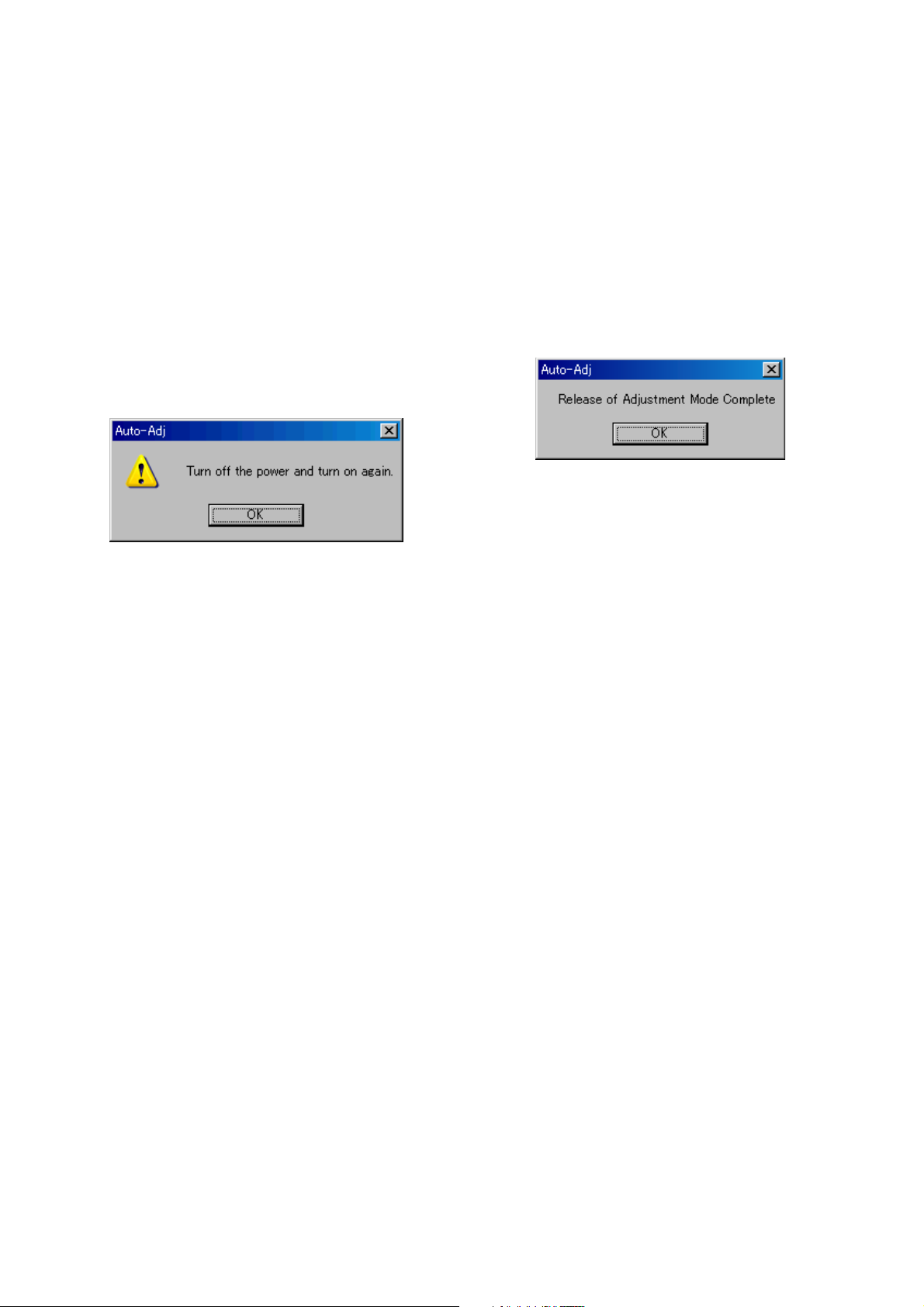
4) When the following message is displayed, turn off and on again
the power switch of the Camcorder.
Note: Turning off and on the power switch causes the
Camcorder to be switched to the Adjustment Mode.
After the Camcorder restarted, click the [OK] button in
the message window.
5) Upon successful completion of the settings in the Adjustment
Mode, the operation of each button on the Main Menu screen
is enabled.
[Releasing method]
1) Click the [END] button on the Main Menu screen.
2) When the following message is displayed, releasing of adjust-
ment mode has completed. Click the [OK] button in the mes-
sage window to exit the Automatic Adjustment Program.
Note: The Camcorder switches to the normal mode by turn-
ing off and on the power switch. After the adjustment
finished, turn off and on again the power switch of the
Camcorder to confirm that the USB SELECT menu is
displayed.
HDR-SR11/SR11E/SR12/SR12E_ADJ
6-8

1-3. HDD SYSTEM ADJUSTMENTS
When the HDD is replaced, the following VBScript files are used.
The Automatic Adjustment Program (HDR-SR11 Series Auto-Adj
Ver_1.[]r[][].exe) is not used.
• CheckHDDError_After2008.vbe
• SetFactoryCheckDefault_After2008.vbe
• SetFactoryCheckFull_After2008.vbe
•ExecAfterFactoryCheck_2008.vbe
For the VBScript files ([][][][][][][].vbe), the program is executed
by double-clicking the file.
Note 1: The VBScript files can only be used on the PC in which
the SeusEX is installed.
Note 2: The VBScript file to be used must include 2008 in the
file name.
HDR-SR11/SR11E/SR12/SR12E_ADJ
6-9

)
1. HDD Replacement Procedure
Note 1: 60GB: HDR-SR11/SR11E
120GB: HDR-SR12/SR12E
Note 2: Select correct capacity and retry, if the HDD capacity
setting was wrong.
Start
Connect the camcorder to the PC
with a USB cable, and turn on the
power switch.
The USB SELECT menu will appear
on the LCD screen of the camcorder,
and the select “USB CONNECT” to
establish the connection.
Execte the “CheckHDDError_After2008.vbe”.
(Double-click the file.)
Message is checked.
When message is
“No Error”
Replacing the HDD is unneccessary.
End
(See page 6-11)
When message is
“Error Detected”
A
B
(See page 6-11
HDR-SR11/SR11E/SR12/SR12E_ADJ
6-10
Note: During the execution of Factory Check, the LCD screen of
the camcorder becomes gray, and the ACCESS lamp becomes dark and light.
When the Factory Check finished, the LCD screen changes
as follows:
When Factory Check is OK: Camera image display
When Factory Check is NG: Blue display
(See page 6-10)
B
Ye s
New HDD
Execte the
“SetFactoryCheckDefault_After2008.vbe”.
(Double-click the file.)
Wait until “JOB Success”
message is displayed.
(several seconds)
Is replacement HDD new one?
Turn off the power of camcorder.
Turning on the power of camcorder
will start automatic Factory Check.
No
Reused HDD
Execte the
“SetFactoryCheckFull_After2008.vbe”.
(Double-click the file.)
Wait until “JOB Success”
message is displayed.
(several seconds)
Replace the HDD.
Wait until Factory Check completed. (Note)
[EST. PROCESS TIME]
Default: 6 min.
Full:
40GB About 2 hour 36 min.
60GB About 3 hour 36 min.
120GB About 7 hour 15 min.
Execte the
“ExecAfterFactoryCheck_2008.vbe”.
(Double-click the file.)
HDR-SR11/SR11E/SR12/SR12E_ADJ
Wait until “JOB Success”
message is displayed.
(several seconds)
A
(See page 6-10)
6-11
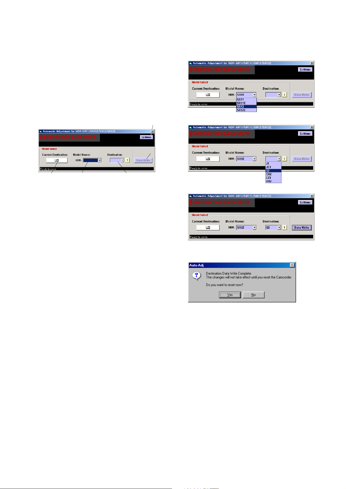
1-4. DESTINATION DATA WRITE
Note: The DESTINATION DATA WRITE can be set with the
Service board only.
Performing the DESTINATION DATA WRITE with other
than the Service board causes the error (E:20:00 will be
blinking) and the power to be shut down.
1. Function of Each Button on Destination Data Write
Screen
Click the [DESTINATION DATA WRITE] button on the Main Menu
screen, and the “DESTNATION DATA WRITE” screen in Fig. 61-10 will appear.
1
5
2. Destination Data Write
[Writing method]
1) Select the model name from the pulldown list.
2) Select the target destination from the pulldown list.
2
3
4
Fig. 6-1-10
1 [To Menu] button
Return to the main menu.
2 Destination Check button
Current destination setting checked when the “DESTINATION
DATA WRITE” screen started is displayed.
When this button is clicked, the destination is checked and the
display is updated.
3 Model Name List
Selects the model name.
4 Destination List
Selects the written destination.
5 [Data Write] button
Write the destination data to the camcorder.
3) Click the [Data Write] button.
4) Following message will be appeared after completing data
writing.
5) After the destination data writing completed, click the Destination Check button to check the destination.
HDR-SR11/SR11E/SR12/SR12E_ADJ
6-12
Ver. 1.1 2008.05
3. Selectable Language Table
SELECTABLE LANGUAGE
DESTINATION
J1 J
U2 US
E23
KR2 KR
JE3
NTSC model
CA2
E34 E
TH6
HK1
AU2
CN2 CH
JE3
PAL model
CEL
CEH
CEN
E
JE
CND
Thai
HK
AUS
JE
NE
UK
AEP
AREA
English
z
z aaa a
z aaaaaa
a aaaaza
z aaaaaa
z aaaaaa
z aaaaaaaaa a aaaa aa
z aaaaaaaaa a aaaa aa
z aaaaaaaaa a aaaa aa
z aaaaaaaaa a aaaa aa
a aaaaaazaa a aaaa aa
z aaaaaaaaa a aaaaaaaaaa
z aaaaaaaaa a a aaaaa
z aaaaa aaa a a aaaaa
z aaaaa aaa a a aaaaa
z: INITIAL LANGUAGE
French
Japanese
Italian
German
Spanish
Dutch
Russian
Simplified Chinese
Greek
Portuguese
Braz.Portuguese
Korean
Espanyol
Canadian French
Traditional Chinese
Simplified English
Arabic
Persian
Thai
Polish
Turkish
Czech
Table 6-1-2
Melayu
Indonesia
Hungarian
HDR-SR11/SR11E/SR12/SR12E_ADJ
6-13
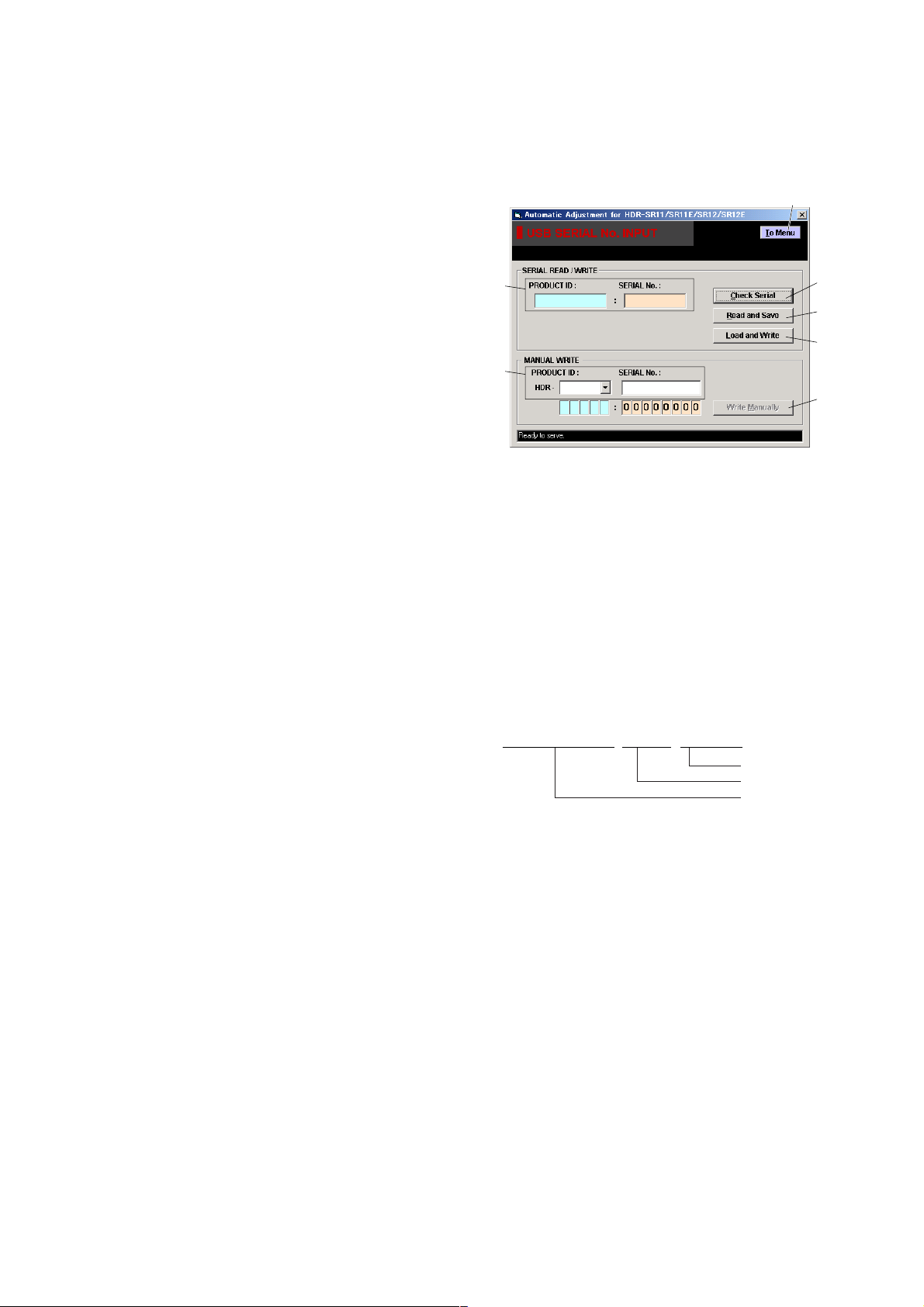
1-5. USB SERIAL No. INPUT
HDR-SR11_SERIAL_xxxxxxxx_yyyymmdd.dat
Date
USB serial number
Data name
The set is shipped with a unique ID (USB Serial No.) written in it.
This ID has not been written in a new board for service, and therefore it must be entered after the board replacement.
If original ID can be read from the board before replacement, read
it from the board before replacement using the “SERIAL READ/
WRITE” screen, and then write it after replacement.
If original ID cannot be read from the board before replacement,
write the ID for service using the “MANUAL WRITE” screen.
(The ID for service is different from the ID written when the set is
shipped.) Enter the PRODUCT ID (last 5 characters of model name)
and SERIAL No. into the screen and write them.
1. Function of Each Button on USB Serial No. Input
Screen
Click the [USB SERIAL No. INPUT] button on the Main Menu screen,
and the “USB SERIAL No. INPUT” screen in Fig. 6-1-11 will
appear.
1
2
6
3
4
5
7
Fig. 6-1-11
1 [To Menu] button
Return to the main menu.
2 Display area
The “PRODUCT ID” and “SERIAL No.” are displayed.
3 [Check Serial] button
The USB SERIAL No. data is read from the camcorder and
displayed in the display area.
4 [Read and Save] button
The USB SERIAL No. data is read from the camcorder and
saved in PC as a file.
Default file name is as follows:
5 [Load and Write] button
The USB SERIAL No. data is loaded from the file saved in
PC and written to the camcorder.
6 Input area
Enter “PRODUCT ID” and “SERIAL No.” when writing the
ID for service.
The “PRODUCT ID” is set from the last 5 characters of model
name if the model name is selected.
For the “SERIAL No.”, read it from the label on the camcorder
body and enter it.
7 [Write Manually] button
The USB SERIAL No. data entered in the input area is written
to the camcorder.
HDR-SR11/SR11E/SR12/SR12E_ADJ
6-14
 Loading...