

Page 1
AS
FILE NO.
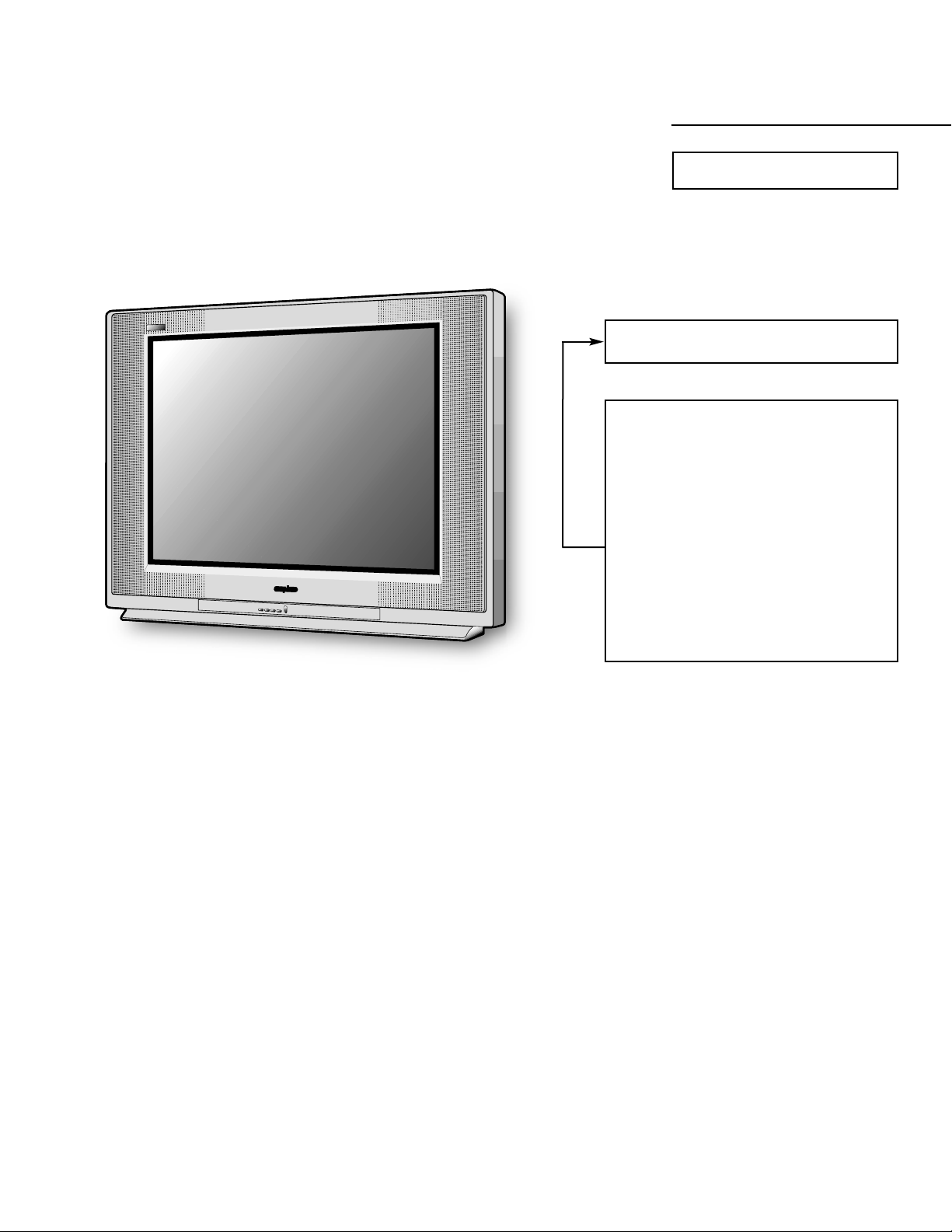
SERVICE MANUAL Remote Control Digital
Color T elevision
HT32744 (U.S.A.)
(CANADA)
ORIGINAL VERSION
Chassis No. 32744-00
NOTE: Match the Chassis No. on
the unit’s back cover with
the Chassis No. in the
Service Manual.
If the Original Version
Service Manual Chassis
No. does not match the
unit’s, additional Service
Literature is required. You
must refer to “Notices” to the
Original Service Manual
prior to servicing the unit.
Contents
Safety Instructions . . . . . . . . . . . . . . . . . . 2
Service Adjustments. . . . . . . . . . . . . 3 - 17
Service Hints. . . . . . . . . . . . . . . . . . . . . . 18
Mechanical Disassemblies. . . . . . . . . . . 19
Chassis Electrical Parts List . . . . . . 20 - 40
Cabinet Parts List . . . . . . . . . . . . . . . . . . 41
Component and Test Point
Locations . . . . . . . . . . . . . . . . . . . 42 - 49
Block Diagrams . . . . . . . . . . . . . . . . 50 - 55
Troubleshooting Flow Charts . . . . . 56 – 58
Control Port Function . . . . . . . . . . . . . . . 59
Schematic Inserts . . . . . . . . . . . . . . 61 – 76
Schematic Notes . . . . . . . . . . . . . . . . . 61
Pin Layouts . . . . . . . . . . . . . . . . . . . . . 61
Capacitor and Resistor Codes . . . . . . 61
Board Connections & Locations. 62 – 64
Waveforms. . . . . . . . . . . . . . . . . . 62 – 64
Main Board. . . . . . . . . . . . . . . . . . 65 – 68
A/V Select and Video Boards . . . 69 – 72
VM Board. . . . . . . . . . . . . . . . . . . . . . . 73
CRT Socket Board . . . . . . . . . . . . . . . . 73
Power and Deflection Board. . . . 74 – 76
Front Board . . . . . . . . . . . . . . . . . 74 – 75
Specifications
Power Rating . . . . . . . . . . . . . . . . . . . . . 120V, 60Hz
140W (Avg), 2.5A (Max)
Antenna Input Impedance. . . . . . . . . . . . . . . . . 75Ω
UHF/VHF/CATV
Digital
Receiving Channel . . . . . . . . . . . . . . . . 2 - 13 (VHF),
14 - 69 (UHF),
01, 14 - 94, 95 - 125 (CATV)
1 - 99 (Digital)
Remote Ready . . . . . . . . . . 52 Key Remote Control
Sound Output . . . . . . . . . . . . . . . . . . . . . . 5.0 W/CH
Intermediate Frequency
Picture IF Carrier. . . . . . . . . . . . . . . . . . 45.75MHz
Sound IF Carrier . . . . . . . . . . . . . . . . . . 41.25MHz
Color Sub Carrier . . . . . . . . . . . . . . . . . 42.17MHz
Picture Tube. . . . . . . . . . . . . . . . . . . A80ERF082X44
Semiconductors
Integrated Circuits . . . . . . . . . . . . . . . . . . . . . . . 40
Transistors. . . . . . . . . . . . . . . . . . . . . . . . . . . . . 89
Except within Tuner, RC Pre-Amp. & Digital Module
Cabinet Dimensions
Width. . . . . . . . . . . . . . . . . . . . . . . . . . . . . 888 mm
Height . . . . . . . . . . . . . . . . . . . . . . . . . . . . 687 mm
Depth. . . . . . . . . . . . . . . . . . . . . . . . . . . . . 570 mm
REFERENCE No. SM780095
HT32744,H3ELM, PRODUCT CODE 111369990
A
S
Page 2
— 2 —
SAFETY PRECAUTIONS
WARNING: The chassis of this receiver has a floating
ground with the potential of one half the AC line voltage in
respect to earth ground. Service should not be attempted by
anyone not familiar with the precautions necessary when
working on this type of equipment.
The following precautions must be observed:
1. An isolation transformer must be connected in the power
line between the receiver and the AC line before any service is performed on the receiver.
2. Comply with all caution and safety-related notes provided on the side of the cabinet, inside the cabinet, on the
chassis, and the picture tube.
3. When replacing a chassis in the cabinet, always be certain
that all the protective devices are installed properly, such
as control knobs, adjustment covers, shields and barriers.
DO NOT OPERATE THIS TELEVISION RECEIVER
WITHOUT THE PROTECTIVE SHIELD IN POSITION AND
PROPERLY SECURED.
4. Before replacing the back cover of the set, thoroughly
inspect the inside of the cabinet to see that no stray parts
or tools have been left inside.
Before returning any television to the customer, the
service technician must perform the following safety
checks to be sure that the unit is completely safe to
operate without danger of electrical shock.
ANTENNA COLD CHECK
Remove AC plug from the 120 VAC outlet and place a
jumper across the two blades. Connect one lead of an ohmmeter to the jumpered AC plug, and touch the other lead to
each exposed antenna terminal (UHF and VHF antenna terminals). The resistance must measure between 1M ohm and
5.2M ohm. Any resistance value below or above this range
indicates an abnormality which requires corrective action.
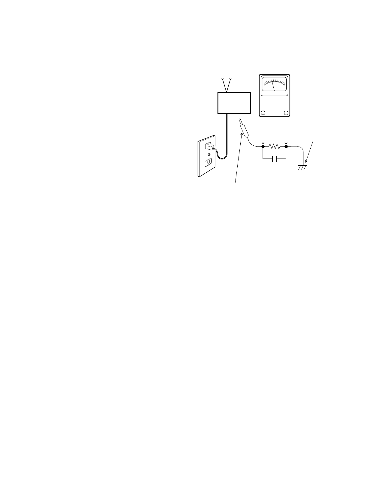
LEAKAGE CURRENT CHECK
Plug the AC line cord directly into a 120 VAC outlet. (Do not
use an isolation transformer for this check.) Use an AC voltmeter, that has 5000 ohms per volt or more sensitivity.
Connect a 1500 ohm 10 watt resistor, paralleled by a 0.15 µF
150 VAC capacitor, between a known good earth ground
(water pipe, conduit, etc.) and all exposed metal parts of the
cabinet (antennas, handle bracket, metal cabinet, screw
heads, metal overlays, control shafts, etc.). Measure the AC
voltage across the 1500 ohm resistor. The AC voltage
should not exceed 750 mV. A reading exceeding 750 mV
indicates that a dangerous potential exists. The fault must
be located and corrected. Repeat the above test with the
receiver power plug reversed.
NEVER RETURN A RECEIVER TO THE CUSTOMER
WITHOUT TAKING THE NECESSARY CORRECTIVE ACTION.
X-RADIATION PRECAUTION
The primary source of X-RADIATION in solid-state receivers is
the picture tube. The picture tube is specially constructed to
limit X-Ray emission. For continued X-RADIATION protection,
the replacement tube must be the same type as the original
(including the suffix letter in the part numbers). Excessive high
voltage may produce potentially hazardous X-RADIATION. To
avoid such hazards, the high voltage must be maintained within
specific limits. Refer to the X-RADIATION WARNING NOTE on
the CHASSIS SCHEMATIC in this service manual for specific
high voltage limits. If the high voltage exceeds specified limits,
check the components specified on the chassis schematic
diagram and take the necessary corrective action. Carefully
follow the instructions for the +B Voltage Check and the High
Voltage Check to maintain the high voltage within the specified
limits.
HIGH VOL T AGE HOLD-DOWN TEST
To prevent X-RADIATION from the picture tube due to
excessive high voltage, a HOLD-DOWN circuit is provided in
the high voltage circuit. Every time the receiver is serviced,
the high voltage HOLD-DOWN circuit must be tested for
proper operation. Refer to the HIGH VOLTAGE HOLDDOWN TEST in service adjustments.
PRODUCT SAFETY NOTICE
When replacing components in a receiver, always keep in
mind the necessary product safety precautions. Pay special
attention to the replacement of components marked with a
star (★) in the parts list and in the schematic diagrams. To
ensure safe product operation, it is necessary to replace
those components with the exact same PARTS.
SAFETY INSTRUCTIONS
READING SHOULD NOT EXCEED 750 mV.
AC VOLTMETER
(5000 ohms per volt or more sensitivity)
TELEVISION
RECEIVER
Good earth ground
such as a water pipe,
conduit, etc.
AC OUTLET
1500 ohm
10 watt
0.15 µF 150V AC
To be touched to all of exposed metal parts.
Voltmeter Hook-up for Leakage Current Check.
Page 3
GENERAL
This set has an On-screen Service Menu system included in the CPU that allows remote operation for most of the service adjustments.
ON-SCREEN SERVICE MENU SYSTEM
1. Enter the Service Menu:
• While pressing the – VOLUME key on the front control panel,
reconnect the AC power cord. The Service Menu Display will now
appear. The remote can now be used to make adjustments.
See Figure 1.
2. Service Adjustments:
• Press theChannel ▲ or ▼ key to select the desired service
menu you want to adjust. See page 5 for On-screen Service
Menu.
• Use the Volume + or – key or numeric keys to adjust the data.
(For Sub - Address see below)
3. Exit from the Service Menu:
• Press the MENU key to turn off the Service Menu display.
ADJUSTMENT FOR SUB ITEM (ADDRESS)
Some service data have Sub - Addresses. Use the numeric keys (from 0 to 7), to adjust the Sub - item data.
ADJUST DATA OF SUB-TITLE
1. Find the title and its bit of binary data from Table 1 (On-Screen Service Menu).
2. Enter the service menu (see above) and select the item number needed with the Channel ▲ or ▼ key.
3. With the numeric key (from 0 to 7), change the bit data. Each time the numeric key is pressed, the data changes from 0 to
1 alternately. For example, to change the data of bit 5, press the “5” key.
NOTE: The ▲ and ▼ symbols used in the following service adjustments refer to the Channel up and down keys not the
Menu keys.
SERVICE AD JUSTMENTS
— 3 —
XXXXXXXXXXX
XX XX XXXXXXXX
Figure 1. Service Menu Display
ITEM NO.
TITLE
BINARY DATA
(8 bit)
HEXADECIMAL
DATA
(b7) (b6) (b5) (b4) (b3) (b2) (b1) (b0)
0 1 0 1 0 1 1 0
BINARY DATA
(8 bit)
IC802 (EEPROM) REPLACEMENT
When IC802 (EEPROM) is replaced, IC801 (CPU) will automatically write the initial reference data into IC802 for basic TV operation.
However, the bus data should be checked and some bus data should be set up before attempting the service adjustments.
(See Table 1. on pages 5 – 13 for detailed bus data information.)
INITIAL BUS DATA SETUP
Note: When IC802 (EEPROM) is replaced, change the following initial reference data for proper TV operation before
attempting service adjustments.
1. Disconnect the AC power cord (AC 120V line).
2. While pressing the MENU key, reconnect the AC power cord. The Service Menu display will now appear.
3. Select NO. 102 SHU2PO (Sub Hue / Pre/Over Shoot) with ▲ or ▼ key. Adjust the data with number keys for 1F.
4. Select NO. 103 SLC2CTI (Sub Color / CTI Level) with ▲ or ▼ key. Adjust the data with number keys for 21.
5. Select NO. 105 SSH2LTI (Sub Sharp / LTI Level) with ▲ or ▼ key. Adjust the data with number keys for 89.
6. Select NO. 106 RD2PTL (R Drive / P Limit Level) with ▲ or ▼ key. Adjust the data with number keys for 70.
7. Select NO. 108 BD2CTIM1 (B Drive / CTI Mode) with ▲ or ▼ key. Adjust the data with number keys for 78.
8. Select NO. 109 SBR2GAM (Sub Bright / Gamma) with ▲ or ▼ key. Adjust the data with number keys for 26.
9. Select NO. 10A RCT2LTIM1 (R Cutoff / LTI Mode) with ▲ or ▼ key. Adjust the data with number keys for 88.
9. Select NO. 10B GCT2DPL (G Cutoff / DPIC Level) with ▲ or ▼ key. Adjust the data with number keys for 5D.
10. Select NO. 10C BCT2DCT (B Cutoff / DC Transit) with ▲ or ▼ key. Adjust the data with number keys for 75.
11. Select NO. 10F CBOF2AW1AB (CB Offset / Aging W / Aging B) with ▲ or ▼ key. Adjust the data with number keys for 94.
12. Select NO. 110 CROF2SYS (CR Offset / System ) with ▲ or ▼ key. Adjust the data with number keys for B8.
13. Select NO. 114 VML4FLC2FLS (VM Level / FLCOL / FLCOL Switch) with ▲or ▼ key. Adjust the data with number keys for F2.
14. Select NO. 116 VS (V Size ) with ▲ or ▼ key. Adjust the data with number keys for B6.
Page 4

— 4 —
SERVICE AD JUSTMENTS (Cont.)
INITIAL BUS DATA SETUP (Cont.)
15. Select NO. 117 VPS (V Position) with ▲ or ▼ key. Adjust the data with number keys for 64.
16 Select NO. 119 HSI2UUC (H Size / Up UCP) with ▲ or ▼ key. Adjust the data with number keys for 48.
17. Select NO. 11A PAP2LUP (Pin Amp / Lo UCP) with ▲ or ▼ key. Adjust the data with number keys for 80.
18. Select NO. 11B UCP 2UUG (Up CPin / Up UCG) with ▲ or ▼ key. Adjust the data with number keys for 94.
19. Select NO. 11C LCP2LUG (Up CPin / Lo UCG) with ▲ or ▼ key. Adjust the data with number keys A8.
20. Select NO. 11D PPH2UPO1VBS (Pin Phase / Uc Pol / V Blk Sw) with ▲ or ▼ key. Adjust the data with number keys 55.
21. Select NO. 11E HPO2CSH1NIN (H Position / CLP Shift / Non Inter) with ▲or ▼key. Adjust the data with number keys for A5.
22. Select NO. 11F ABO2RAM (AFC Bow / RF AFC Mode) with ▲ or ▼ key. Adjust the data with number keys for 81.
23. Select NO. 120 AAN2AGS1 (AFC Angle / AGC Sw) with ▲ or ▼ key. Adjust the data with number keys for 7C.
24. Select NO. 121 LBK2CPH (Left Blk / CLP Phase) with ▲ or ▼ key. Adjust the data with number keys for BC.
25. Select NO. 122 RBK2CGA1HSW (R Blk / CLP Gate / H Blk Sw) with ▲ or ▼ key. Adjust the data with number keys for 9D.
26. Select NO. 126 VCP4HCP (V Comp / H Comp) with ▲ or ▼ key. Adjust the data with number keys for 76.
27. Select NO. 136 RF-HUE (RF Tint) with ▲ or ▼ key. Adjust the data with number keys for 00.
28. Select NO. 137 RF-COL (RF Color) with ▲ or ▼ key. Adjust the data with number keys for 00.
29. Select NO. 157 RF-SHP (RF Sharpness) with ▲ or ▼ key. Adjust the data with number keys for FE.
30. Select NO. 158 41-SHP (480I Sharpness) with ▲ or ▼ key. Adjust the data with number keys for FE.
31. Select NO. 159 4P-SHP (480P Sharpness) with ▲ or ▼ key. Adjust the data with number keys for FE.
32. Select NO. 15A 1I-SHP (1080I Sharpness) with ▲ or ▼ key. Adjust the data with number keys for FE.
33. Select NO. 15B 7P-SHP (720P Sharpness) with ▲ or ▼ key. Adjust the data with number keys for FE.
34. Select NO. 15C DIGITAL-SHP (Digital Sharpness) with ▲ or ▼ key. Adjust the data with number keys for FE.
35. Select NO. 15E RF-LLV (Rf LTI Level) with ▲ or ▼ key. Adjust the data with number keys for 01.
36. Select No. 171 RF-CB (RF CB Offset) with ▲ or ▼ key. Adjust the data with number keys for 03.
37. Select No. 172 4I-CB (480I CB Offset) with ▲ or ▼ key. Adjust the data with number keys for 03.
38. Select No. 173 4P-CB (480P CB Offset) with ▲ or ▼ key. Adjust the data with number keys for 03.
39. Select No. 174 1I-CB (1080I CB Offset) with ▲ or ▼ key. Adjust the data with number keys for FF.
40. Select No. 175 7P-CB (720P CB Offset) with ▲ or ▼ key. Adjust the data with number keys for FF.
41. Select No. 176 D-CB (Digital CB Offset) with ▲ or ▼ key. Adjust the data with number keys for F8.
42. Select No. 178 RF-CR (RF CR Offset) with ▲ or ▼ key. Adjust the data with number keys for 02.
43. Select No. 179 4I-CR (480I CR Offset) with ▲ or ▼ key. Adjust the data with number keys for FE.
44. Select No. 17A 4P-CR (480P CR Offset) with ▲ or ▼ key. Adjust the data with number keys for FE.
45. Select No. 17B 1I-CR (1080I CR Offset) with ▲ or ▼ key. Adjust the data with number keys for F6.
46. Select No. 17C 7P-CR (720P CR Offset) with ▲ or ▼ key. Adjust the data with number keys for F6.
47. Select No. 17D D-CR (Digital CR Offset) with ▲ or ▼ key. Adjust the data with number keys for F6.
48. Select No. 184 D-SYS (Digital System) with ▲ or ▼ key. Adjust the data with number keys for 01.
49. Select No. 1D3 CWUBK (Video 1/2 Letter Box Lo Blk) with ▲ or ▼ key. Adjust the data with number keys for 08.
50. Select No. 1D4 CWLBK (Video 1/2 Letter Box Up Blk) with ▲ or ▼ key. Adjust the data with number keys for 0B.
51. Select No. 1FA 4PWLBK (480P letter Box Lo Blk) with ▲ or ▼ key. Adjust the data with number keys for 0B.
52. Select No. 20C 7PWUBK (720P Letter Box Up Blk) with ▲ or ▼ key. Adjust the data with number keys for 08.
53. Select No. 20D 7PWLBK (720P letter Box Lo Blk) with ▲ or ▼ key. Adjust the data with number keys for 0B.
54. Select No. 21F 1IWUBK (1080I-Letter Box Up Blk) with ▲ or ▼ key. Adjust the data with number keys for 08.
55. Select No. 220 1IWLBK (1080I-Letter Box Lo Blk) with ▲ or ▼ key. Adjust the data with number keys for 0B.
56. Select No. 22B DVPS (Digital - Full V Position) with ▲ or ▼ key. Adjust the data with number keys for 01.
57. Select No. 258 PUBK (PAP-On Up Blk) with ▲ or ▼ key. Adjust the data with number keys for 08.
58. Select No. 259 PLBK (PAP-On Lo Blk) with ▲ or ▼ key. Adjust the data with number keys for 0B.
59. Select No. 26B DWUBK (Digital Letter Box Up Blk) with ▲ or ▼ key. Adjust the data with number keys for 08.
60. Select No. 26C DWLBK (Digital Letter Box Lo Blk) with ▲ or ▼ key. Adjust the data with number keys for 0B.
61. Select No. 043 SHU4SCL (Sub Hue / Sub Color) with ▲ or ▼ key. Adjust the data with number keys for 72.
62. Select No. 045 YD3SF2FO1CM2 (Y Drive / SHP-FO / FSC Out / CD Mode) with ▲ or ▼ key. Adjust the data with number
keys for 32.
63. Select No. 053 HP2V11V2 (HP / V1/ V2) with ▲ or ▼ key. Adjust the data with number keys for 7B.
64. Select No. 088 OP2 (Option 2) with ▲ or ▼ key. Adjust the data with number keys for 10.
65. Select No. 08C AKB (AKB Detect Time) with ▲ or ▼ key. Adjust the data with number keys for 10.
66. Press the MENU key to turn off the Service Menu display.
Page 5
— 5 —
Table 1. ON-SCREEN SERVICE MENU
When IC802 (EEPROM) is replaced, check the bus data to confirm they are the same as below. The shaded menu should be
checked and be set up or readjusted according to the procedures described in the following pages. Initial Setup Data marked
with an * should be changed from Initial Reference Data. (See pages 3 and 4 for Initial Bus Data Setup.)
No. TITLE
INITIAL REFERENCE INITIAL SETUP INITIAL SETUP
FUNCTION
DATA HEX DATA HEX DATA BINARY
100 PRGBON4DL2ES1SF FD FD 11111101 PIC+R+G+B On(7~4), D COL(3~2), ES1(1):0(fixed), SF(0)
101 BLKBTM 00 00 00000000 BLK_BTM(1~0)
102 SHU2PO 23 1F* 00011111 SUB HUE(7~2), PRE/OVER(1~0)
103 SCL2CTI 3D 21* 00100001 SUB COLOR(7~2), CTI_LEV(1~0)
104 ↓↓↓↓NOT USED
105 SSH2LTI 81 89* 10001001 SUB SHARPNESS(7~2), LTI_LEV(1~0)
106 RD2PTL 7C 70* 01110000 R_DRIVE(7~2), PLIMIT_LEV(1~0)
107 GD2ABLM 7F 7F 01111111 G_DRIVE(7~2), ABL_MODE(1~0)
108 BD2CTIM1 7C 70* 01111000 B_DRIVE(7~2), CTI_MODE(1)
109 SBR2GAM 3E 26* 00100110 SUB_BRIGHT(7~2), GAMMA(1~0)
10A RCT2LTIM1 7C 88* 10001000 R_CUTOFF(7~2), LTI_MODE(1)
10B GCT2DPL 7F 5D* 01011101 G_CUTOFF(7~2), DPIC_LEV(1~0)
10C BCT2DCT 7F 75* 01110101 B_CUTOFF(7~2), DC_TRAN(1~0)
10D SCO4LR2L 57 57 01010111 SUB_CONT(7~4), LRGB2_LEV(3~0)
10E PABL4ABLT F1 F1 11110001 P_ABL(7~4), ABL_TH(3~0)
10F CB0F2AW1AB 90 94* 10010100 CB_OFFSET(7~2), AGING_W(1), AGING_B(0)
110 CROF2SYS B0 B8* 10111000 CR_OFFSET(7~2), SYSTEM(1~0)
111 YOF4VD2VF 02 02 00000010 Y_OFFSET(7~4), VM_DLY(3~2), VM_FO(1~0)
112 RYR4RYB 88 88 10001000 R-Y/R(7~4), R-Y/B(3~0)
113 GYR4GYP 88 88 10001000 G-Y/R(7~4),G-Y/B(3~0)
114 VML4FLC2FLS F8 F2* 11110010 VM_LEV(7~4), FLCOL(3~2), FLCOL SW(1)
115 UBK4LBK 00 00 00000000 UP_BLK(7~4), LO_ BLK(3~0)
116 VS BE B6* 10110110 V_SIZE(7~2), bit1:1 bit0:0 (b1/b0: fixed)
117 VPS 78 64* 01010100 V_POSITION(7~2)
118 VLI4SCR 76 76 01110110 V_LIN(7~4), S_CORRECTION(3~0)
119 HSI2UUC 61 48* 01001000 H_SIZE(7~2), UP_UCP(1~0)
11A PAP2LUP B5 80* 10000000 PIN AMP(7~2), LO UCP(1~0)
11B UCP2UUG 8D 94* 10010100 UP_CPIN(7-2), UP_UCG(1-0)Y
11C LCP2LUG 99 A8* 10101000 LO_CPIN(7-2), LO_UCG(1-0)
11D PPH2UPO1VBS 83 55* 01010101 PIN_PHASE(7-2), UC_POL(1), VBLK_SW(0)
11E HPO2CSH1NIN 9C A5* 10100101 H_POSITION(7-2), CLP_SHIFT(1),NONINTER(0)
11F ABO2RAM 85 81* 10000001 AFC_BOW(7-2), RF AFC_MODE(1-0)
120 AAN2AGS1 84 7C* 01111100 AFC_ANGLE(7-2), AGC_SW(1)
121 LBK2CPH E0 BC* 10111100 LEFT_BLK(7-2), CLP_PHASE(1-0)
122 RBK2CGA1HSW 71 9D* 10011101 RIGHT_BLK(7-2), CLP_GATE(1), HBLK_SW(0)
123 VAS2JSW 00 00 00000000 V_ASPECT(7-2), JMP_SW (0)
124 VSR 7D 7D 01111101 V_SCROLL(7-2), b1 : 0, b0 : 1 (b1 / b0: fixed)
125 UVL4LVL 00 00 00000000 UP_VLIN(7-4), LO_VLIN(3-0)
126 VCP4HCP 49 76* 01110110 V_COMP(7-4), H_COMP(3-0)
127 ATI3HVS2BOF1AOF 70 70 01110000 AKB-TIM(7-3), HVBTM_SW(2),BLK OFF(1), AKB OFF(0)
128 128 00 00 00000000 PRELIMINARY
129 RF-SF0 01 01 00000001 RF SHP_F0(0)
12A 4I-SF0 01 01 00000001 480I SHP_F0(0)
12B 4P-SF0 01 01 00000001 480P SHP_F0(0)
12C 1I-SF0 01 01 00000001 1080I SHP_F0(0)
12D 7P-SF0 01 01 00000001 720P SHP_F0(0)
12E D-SF0 01 01 00000001 DIGITAL SHP_F0(0)
12F RF-CON 00 00 00000000 RF CONTRAST
130 4I-CON 00 00 00000000 480I CONTRAST
131 4P-CON 00 00 00000000 480P CONTRAST
Page 6

Table 1. ON-SCREEN SERVICE MENU (Continued)
— 6 —
SERVICE AD JUSTMENTS (Cont.)
No. TITLE
INITIAL REFERENCE INITIAL SETUP INITIAL SETUP
FUNCTION
DATA HEX DATA HEX DATA BINARY
132 1I-CON 00 00 00000000 1125I CONTRAST
133 7P-CON 00 00 00000000 720P CONTRAST
134 D-CON 00 00 00000000 DIGITAL CONTRAST
135 W-CON 00 00 00000000 LETTER BOX CONTRAST
136 RF-HUE FC 00* 00000000 RF TINT
137 4I-HUE 00 00 00000000 480I TINT
138 4P-HUE 00 00 00000000 480P TINT
139 1I-HUE 00 00 00000000 1080I TINT
13A 7P-HUE 00 00 00000000 720P TINT
13B D-HUE 00 00 00000000 DIGITAL TINT
13C W-HUE FF FF 11111111 LETTER BOX TINT
13D RF-PRE 02 02 00000010 RF PRE/OVER(1-0)
13E 4I-PRE 03 03 00000011 480I PRE/OVER(1-0)
13F 4P-PRE 03 03 00000011 480P PRE/OVER(1-0)
140 1I-PRE 03 03 00000011 1080I PRE/OVER(1-0)
141 7P-PRE 03 03 00000011 720P PRE/OVER(1-0)
142 D-PRE 03 03 00000011 DIGITAL PRE/OVER(1-0)
143 RF-COL 01 00* 00000000 RF COLOR
144 4I-COL 04 04 00000100 480I COLOR
145 4P-COL 05 05 00000101 480P COLOR
146 1I-COL 04 04 00000100 1080I COLOR
147 7P-COL 04 04 00000100 720P COLOR
148 D-COL 00 00 00000000 DIGITAL COLOR
149 W-COL 00 00 00000000 LETTER BOX COLOR
14A RF-CLV 01 01 00000001 RF CTI_LEV(1-0)
14B 4I-CLV 01 01 00000001 480I CTI_LEV(1-0)
14C 4P-CLV 01 01 00000001 480P CTI_LEV(1-0)
14D 1I-CLV 01 01 00000001 1080I CTI_LEV(1-0)
14E 7P-CLV 01 01 00000001 720P CTI_LEV(1-0)
14F D-CLV 01 01 00000001 DIGITAL CTI_LEV(1-0)
150 RF-BRI 00 00 00000000 RF BRIGHT
151 4I-BRI 00 00 00000000 480I BRIGHT
152 4P-BRI 00 00 00000000 480P BRIGHT
153 1I-BRI 00 00 00000000 1080I BRIGHT
154 7P-BRI 00 00 00000000 720P BRIGHT
155 D-BRI 00 00 00000000 DIGITAL BRIGHT
156 W-BRI 00 00 00000000 LETTER BOX BRIGHT
157 RF-SHP 00 FE* 11111110 RF SHARPNESS
158 4I-SHP 00 FE* 11111110 480I SHARPNESS
159 4P-SHP 00 FE* 11111110 480P SHARPNESS
15A 1I-SHP 00 FE* 11111110 1080I SHARPNESS
15B 7P-SHP 00 FE* 11111110 720P SHARPNESS
15C DIGITAL-SHP 00 FE* 00000000 DIGITAL SHARPNESS
15D W-SHP 00 00 00000000 LETTER BOX SHARPNESS
15E RF-LLV 00 01* 00000001 RF LTI_LEV(1-0)
15F 4I-LLV 01 01 00000001 480I LTI_LEV(1-0)
160 4P-LLV 01 01 00000001 480P LTI_LEV(1-0)
161 1I-LLV 01 01 00000001 1080I LTI_LEV(1-0)
162 7P-LLV 01 01 00000001 720P LTI_LEV(1-0)
163 D-LLV 01 01 00000001 DIGITAL LTI_LEV(1-0)
Page 7

— 7 —
No. TITLE
INITIAL REFERENCE INITIAL SETUP INITIAL SETUP
FUNCTION
DATA HEX DATA HEX DATA BINARY
164 RF-CMD 00 00 00000000 RF CTI_MODE(0)
165 4I-CMD 00 00 00000000 480I CTI_MODE(0)
166 4P-CMD 00 00 00000000 480P CTI_MODE(0)
167 1I-CMD 00 00 00000000 1080I CTI_MODE(0)
168 7P-CMD 00 00 00000000 720P CTI_MODE(0)
169 D-CMD 00 00 00000000 DIGITAL CTI_MODE(0)
16A 1I-GAM 02 02 00000010 1125I ÇfAMMA(1-0)
16B RF-LMD 00 00 00000000 RF LTI_MODE(0)
16C 4I-LMD 00 00 00000000 480I LTI_MODE(0)
16D 4P-LMD 00 00 00000000 480P LTI_MODE(0)
16E 1I-LMD 00 00 00000000 1080I LTI_MODE(0)
16F 7P-LMD 00 00 00000000 720P LTI_MODE(0)
170 D-LMD 00 00 00000000 DIGITAL LTI_MODE(0)
171 RF-CB 00 03* 00000011 RF CB_OFFSET
172 4I-CB 00 03* 00000011 480I CB_OFFSET
173 4P-CB F0 03* 00000011 480P CB_OFFSET
174 1I-CB F0 FF* 11111111 1080I CB_OFFSET
175 7P-CB F0 FF* 11111111 720P CB_OFFSET
176 D-CB F0 F8* 11111000 DIGITAL CB_OFFSET
177 W-CB 00 00 00000000 000000 LETTER BOX CB_OFFSET
178 RF-CR 00 02* 00000010 RF CR_OFFSET
179 4I-CR 00 FE* 11111110 480I CR_OFFSET
17A 4P-CR F0 FE* 11111110 480P CR_OFFSET
17B 1I-CR F0 F6* 11110110 1080I CR_OFFSET
17C 7P-CR 00 F6* 11110110 720P CR_OFFSET
17D D-CR 00 F6* 11110110 DIGITAL CR_OFFSET
17E W-CR 00 00 00000000 LETTER BOX CR_OFFSET
17F RF-SYS 00 00 00000000 RF SYSTEM(1-0)
180 4I-SYS 00 00 00000000 480I SYSTEM(1-0)
181 4P-SYS 00 00 00000000 480P SYSTEM(1-0)
182 1I-SYS 01 01 00000001 1080I SYSTEM(1-0)
183 7P-SYS 01 01 00000001 720P SYSTEM(1-0)
184 D-SYS 00 01* 00000001 DIGITAL SYSTEM(1-0)
185 RF-VMD 00 00 00000000 RF VM_DLY(1-0)
186 4I-VMD 00 00 00000000 480I VM_DLY(1-0)
187 4P-VMD 00 00 00000000 480P VM_DLY(1-0)
188 1I-VMD 00 00 00000000 1080I VM_DLY(1-0)
189 7P-VMD 00 00 00000000 720P VM_DLY(1-0)
18A D-VMD 00 00 00000000 DIGITAL VM_DLY(1-0)
18B RF-VMF 02 02 00000010 RF VM_F0(1-0)
18C 4I-VMF 02 02 00000010 480I VM_F0(1-0)
18D 4P-VMF 02 02 00000010 480P VM_F0(1-0)
18E 1I-VMF 02 02 00000010 1080I VM_F0(1-0)
18F 7P-VMF 02 02 00000010 720P VM_F0
190 D-VMF 02 02 00000010 DIGITAL VM_F0
191 W-VMF 02 02 00000010 LETTER BOX VM_F0
192 RF-RYR 08 08 00001000 RF RYR(3-0)
193 4I-RYR 08 08 00001000 480I RYR(3-0)
194 4P-RYR 08 08 00001000 480P RYR(3-0)
195 1I-RYR 08 08 00001000 1080I RYR(3-0)
196 7P-RYR 08 08 00001000 720P RYR(3-0)
197 D-RYR 08 08 00001000 DIGITAL RYR(3-0)
198 RF-RYB 08 08 00001000 RF RYB(3-0)
199 4I-RYB 08 08 00001000 480I RYB(3-0)
Page 8

— 8 —
SERVICE AD JUSTMENTS (Cont.)
Table 1. ON-SCREEN SERVICE MENU (Continued)
No. TITLE
INITIAL REFERENCE INITIAL SETUP INITIAL SETUP
FUNCTION
DATA HEX DATA HEX DATA BINARY
19A 4P-RYB 08 08 00001000 480P RYB(3-0)
19B 1I-RYB 08 08 00001000 1080I RYB(3-0)
19C 7P-RYB 08 08 00001000 720P RYB(3-0)
19D D-RYB 08 08 00001000 DIGITAL RYB(3-0)
19E RF-GYR 08 08 00001000 RF GYR(3-0)
19F 4I-GYR 08 08 00001000 480I GYR(3-0)
1A0 4P-GYR 08 08 00001000 480P GYR(3-0)
1A1 1I-GYR 08 08 00001000 1080I GYR(3-0)
1A2 7P-GYR 08 08 00001000 720P GYR(3-0)
1A3 D-GYR 08 08 00001000 DIGITAL GYR(3-0)
1A4 RF-GYB 08 08 00001000 RF GYB(3-0)
1A5 4I-GYB 08 08 00001000 480I GYB(3-0)
1A6 4P-GYB 08 08 00001000 480P GYB(3-0)
1A7 1I-GYB 08 08 00001000 1080I GYB(3-0)
1A8 7P-GYB 08 08 00001000 720P GYB(3-0)
1A9 D-GYB 08 08 00001000 DIGITAL GYB(3-0)
1AA RF-VLV 0F 0F 00001111 RF VM_LEV(3-0)
1AB 4I-VLV 0F 0F 00001111 480I VM_LEV(3-0)
1AC 4P-VLV 0F 0F 00001111 480P VM_LEV(3-0)
1AD 1I-VLV 0F 0F 00001111 1080I VM_LEV(3-0)
1AE 7P-VLV 0F 0F 00001111 720P VM_LEV(3-0)
1AF D-VLV 0F 0F 00001111 1080I VM_LEV(3-0)
1B0 W-VLV 00 00 00000000 LETTER BOX VM_LEV(3-0)
1B1 1B1 00 00 00000000 PRELIMINARY
1B2 1B2 00 00 00000000 PRELIMINARY
1B3 1B3 00 00 00000000 PRELIMINARY
1B4 1B4 00 00 00000000 PRELIMINARY
1B5 1B5 00 00 00000000 PRELIMINARY
1B6 RWUBK 00 00 00000000 RF-LETTER BOX UP_BLK
1B7 RWLBK 00 00 00000000 RF-LETTER BOX LO_BLK
1B8 RWVS 00 00 00000000 RF-LETTER BOX V_SIZE
1B9 RWVPS 00 00 00000000 RF-LETTER BOX V_POSITION
1BA RWUUC 00 00 00000000 RF-LETTER BOX UP_UCP
1BB RWPAP 00 00 00000000 RF-LETTER BOX PIN_AMP
1BC RWLUP 00 00 00000000 RF-LETTER BOX LO_UCP
1BD RWUCP 00 00 00000000 RF-LETTER BOX UP_CPIN
1BE RWUUG 00 00 00000000 RF-LETTER BOX UP_UCG
1BF RWLCP 00 00 00000000 RF-LETTER BOX LO_CPIN
1C0 RWLUG 00 00 00000000 RF-LETTER BOX LO_UCG
1C1 RWPPH 00 00 00000000 RF-LETTER BOX PIN_PHASE
1C2 RWVBS 00 00 00000000 RF-LETTER BOX VBLK_SW
1C3 RWABO 00 00 00000000 RF-LETTER BOX AFC_BOW
1C4 RWAAN 00 00 00000000 RF-LETTER BOX AFC_ANGLE
1C5 RWVAS 00 00 00000000 RF-LETTER BOX V_ASPECT
1C6 RWJSW 00 00 00000000 RF-LETTER BOX JMP_SW
1C7 RWVSR 00 00 00000000 RF-LETTER BOX V_SCROLL
1C8 1C8 00 00 00000000 RF-LETTER BOX PRELIMINARY
1C9 CFUBK 00 00 00000000 VIDEO1/2-FULL UP_BLK
1CA CFLBK 00 00 00000000 VIDEO1/2-FULL LO_BKL
1CB CFVS 00 00 00000000 VIDEO1/2-FULL V_SIZE
1CC CFVPS 00 00 00000000 VIDEO1/2-FULL V_POSITION
Page 9

— 9 —
No. TITLE
INITIAL REFERENCE INITIAL SETUP INITIAL SETUP
FUNCTION
DATA HEX DATA HEX DATA BINARY
1CD CFHSI 00 00 00000000 VIDEO1/2-FULL H_SIZE
1CE CFHPO 00 00 00000000 VIDEO1/2-FULL H_POSITION
1CF CFLBK 00 00 00000000 VIDEO1/2-FULL L_BLK
1D0 CFRBK 00 00 00000000 VIDEO1/2-FULL R_BLK
1D1 CFVAS 00 00 00000000 VIDEO1/2-FULL V_ASPECT
1D2 CFVSR 00 00 00000000 VIDEO1/2-FULL V_SCROLL
1D3 CWUBK 09 08* 00001000 VIDEO1/2-LETTER BOX LO_BLK
1D4 CWLBK 0D 0B* 00001011 VIDEO1/2-LETTER BOX LO_BLK
1D5 CWVS 00 00 00000000 VIDEO1/2-LETTER BOX V_SIZE
1D6 CWVPS 00 00 00000000 VIDEO1/2-LETTER BOX V_POSITION
1D7 CWVBS 01 01 00000001 VIDEO1/2-LETTER BOX VBLK_SW
1D8 CWVAS 12 12 00010010 VIDEO1/2-LETTER BOX V_ASPECT
1D9 CWJSW 01 01 00000001 VIDEO1/2-LETTER BOX JMP_SW
1DA CWVSR 00 00 00000000 VIDEO1/2-LETTER BOX V_SCROLL
1DB 1DB 00 00 00000000 VIDEO1/2-LETTER BOX PRELIMINARY
1DC 4IUBK 00 00 00000000 480I-FULL UP_BLK
1DD 4ILBK 00 00 00000000 480I-FULL LO_BLK
1DE 4IVS 00 00 00000000 480I-FULL V_SIZE
1DF 4IVPS 00 00 00000000 480I-FULL V_POSITION
1E0 4IHSI 00 00 00000000 480I-FULL H_SIZE
1E1 4IHPO 00 00 00000000 480I-FULL H_POSITION
1E2 4ILBK 00 00 00000000 480I-FULL L_BLK
1E3 4IRBK 00 00 00000000 480I-FULL R_BLK
1E4 4IVAS 00 00 00000000 480I-FULL V_ASPECT
1E5 4IVSR 00 00 00000000 480I-FULL V_SCROLL
1E6 4IWUBK 08 08 00001000 480I-LETTER BOX UP_BLK
1E7 4IWLBK 0B 0B 00001011 480I-LETTER BOX LO_BLK
1E8 4IWVS 00 00 00000000 480I-LETTER BOX V_SIZE
1E9 4IWVPS 00 00 00000000 480I-LETTER BOX V_POSITION
1EA 4IWVBS 01 01 0000000 1480I-LETTER BOX VBLK_SW
1EB 4IWVAS 12 12 00010010 480I-LETTER BOX V_ASPECT
1EC 4IWJSW 01 01 00000001 480I-LETTER BOX JMP_SW
1ED 4IWVSR 00 00 00000000 480I-LETTER BOX V_SCROLL
1EE 1EE 00 00 00000000 480I PRELIMINARY
1EF 4PUBK 00 00 00000000 480P-FULL UP_BLK
1F0 4PLBK 00 00 00000000 480P-FULL LO_BLK
1F1 4PVS 00 00 00000000 480P-FULL V_SIZE
1F2 4PVPS 00 00 00000000 480P-FULL V_POSITION
1F3 4PHSI 00 00 00000000 480P-FULL H_SIZE
1F4 4PHPO 00 00 00000000 480P-FULL H_POSITION
1F5 4PLBK 00 00 00000000 480P-FULL L_BLK
1F6 4PRBK 00 00 00000000 480P-FULL R_BLK
1F7 4PVAS 00 00 00000000 480P-FULL V_ASPECT
1F8 4PVRS 00 00 00000000 480P-FULL V_SCROLL
1F9 4PWUBK 08 08 00001000 480P-LETTER BOX UP_BLK
1FA 4PWLBK 0D 0B* 00001011 480P-LETTER BOX LO_BLK
1FB 4PWVS 00 00 00000000 480P-LETTER BOX V_SIZE
1FC 4PWVPS 00 00 00000000 480P-LETTER BOX V_POSITION
1FD 4PWVBS 01 01 00000001 480P-LETTER BOX VBLK_SW
1FE 4PWVAS 12 12 00010010 480P-LETTER BOX V_ASPECT
1FF 4PWJSW 01 01 00000001 480P-LETTER BOX JMP_SW
200 4PWVSR 00 00 00000000 480P-LETTER BOX V_SCROLL
201 201 00 00 00000000 480P PRELIMINARY
202 7PUBK 00 00 00000000 720P-FULL UP_BLK
Page 10

— 10 —
SERVICE AD JUSTMENTS (Cont.)
Table 1. ON-SCREEN SERVICE MENU (Continued)
No. TITLE
INITIAL REFERENCE INITIAL SETUP INITIAL SETUP
FUNCTION
DATA HEX DATA HEX DATA BINARY
203 7PLBK 00 00 00000000 720P-FULL LO_BLK
204 7PVS 00 00 00000000 720P-FULL V_SIZE
205 7PVPS 00 00 00000000 720P-FULL V_POSITION
206 7PHSI 00 00 00000000 720P-FULL H_SIZE
207 7PHPO 00 00 00000000 720P-FULL H_POSITION
208 7PLBK 00 00 00000000 720P-FULL L_BLK
209 7PRBK 00 00 00000000 720P-FULL R_BLK
20A 7PVAS 00 00 00000000 720P-FULL V_ASPECT
20B 7PVSR 00 00 00000000 720P-FULL V_SCROLL
20C 7PWUBK 09 08* 00001000 720P-LETTER BOX UP_BLK
20D 7PWLBK 0D 0B* 00001011 720P-LETTER BOX LO_BLK
20E 7PWVS 00 00 00000000 720P-LETTER BOX V_SIZE
20F 7PWVPS 00 00 00000000 720P-LETTER BOX V_POSITION
210 7PWVBS 01 01 00000001 720P-LETTER BOX VBLK_SW
211 7PWVAS 12 12 00010010 720P-LETTER BOX V_ASPECT
212 7PWJSW 01 01 00000001 720P-LETTER BOX JMP_SW
213 7PWVSR 00 00 00000000 720P-LETTER BOX V_SCROLL
214 214 00 00 00000000 720P PRELIMINARY
215 1IUBK 00 00 00000000 1080I-FULL UP_BLK
216 1ILBK 00 00 00000000 1080I-FULL LO_BLK
217 1IVS 00 00 00000000 1080I-FULL V_SIZE
218 1IVPS 00 00 00000000 1080I-FULL V_POSITION
219 1IHSI 00 00 00000000 1080I-FULL H_SIZE
21A 1IHPO 00 00 00000000 1080I-FULL H_POSITION
21B 1ILBK 00 00 00000000 1080I-FULL L_BLK
21C 1IRBK 00 00 00000000 1080I-FULL R_BLK
21D 1IVAS 00 00 00000000 1080I-FULL V_ASPECT
21E 1IVSR 00 00 00000000 1080I-FULL V_SCROLL
21F 1IWUBK 09 08* 00001000 1080I-LETTER BOX UP_BLK
220 1IWLBK 0C 0B* 00001011 1080I-LETTER BOX LO_BLK
221 1IWVS 00 00 00000000 1080I-LETTER BOX V_SIZE
222 1IWVPS 00 00 00000000 1080I-LETTER BOX V_POSITION
223 1IWVBS 01 01 00000001 1080I-LETTER BOX VBLK_SW
224 1IWVAS 12 12 00010010 1080I-LETTER BOX V_ASPECT
225 1IWJSW 01 01 00000001 1080I-LETTER BOX JMP_SW
226 1IWVSR 00 00 00000000 1080I-LETTER BOX V_SCROLL
227 227 00 00 00000000 1080I PRELIMINARY
228 DUBK 00 00 00000000 DIGITAL-FULL UP_BLK
229 DLBK 00 00 00000000 DIGITAL-FULL LO_BLK
22A DVS 00 00 00000000 DIGITAL-FULL V_SIZE
22B DVPS 00 01* 00000001 DIGITAL-FULL V_POSITION
22C DHSI 00 00 00000000 DIGITAL-FULL H_SIZE
22D DHPO 00 00 00000000 DIGITAL-FULL H_POSITION
22E DLBK 00 00 00000000 DIGITAL-FULL L_BLK
22F DRBK 00 00 00000000 DIGITAL-FULL R_BLK
230 DVAS 00 00 00000000 DIGITAL-FULL V_ASPECT
231 DVSR 00 00 00000000 DIGITAL-FULL V_SCROLL
232 232 00 00 00000000 DIGITAL PRELIMINARY
233 RZVS 00 00 00000000 RF-ZOOM V_SIZE
234 RZVPS 00 00 00000000 RF-ZOOM V_POSITION
235 RZVBS 00 00 00000000 RF-ZOOM VBLK_SW
Page 11

— 11 —
No. TITLE
INITIAL REFERENCE INITIAL SETUP INITIAL SETUP
FUNCTION
DATA HEX DATA HEX DATA BINARY
236 RZVAS 00 00 00000000 RF-ZOOM V_ASPECT
237 RZZSW 00 00 00000000 RF-ZOOM ZOOM_SW
238 RZVSR 00 00 00000000 RF-ZOOM V_SCROLL
239 239 00 00 00000000 RF PRELIMINARY
23A CZVS 00 00 00000000 VIDEO1/2-ZOOM V_SIZE
23B CZVPS 00 00 00000000 VIDEO1/2-ZOOM V_POSITION
23C CZVAS 00 00 00000000 VIDEO1/2-ZOOM V_ASPECT
23D CZVSR 00 00 00000000 VIDEO1/2-ZOOM V_SCROLL
23E 23E 00 00 00000000 VIDEO1/2 PRELIMINARY
23F 4IZVS 00 00 00000000 480I-ZOOM V_SIZE
240 4IZVPS 00 00 00000000 480I-ZOOM V_POSITION
241 4IZVAS 00 00 00000000 480I-ZOOM V_ASPECT
242 4IZVSR 00 00 00000000 480I-ZOOM V_SCROLL
243 243 00 00 00000000 480I PRELIMINARY
244 4PZVS 00 00 00000000 480P-ZOOM V_SIZE
245 4PZVPS 00 00 00000000 480P-ZOOM V_POSITION
246 4PZVAS 00 00 00000000 480P-ZOOM V_ASPECT
247 4PZVSR 00 00 00000000 480P-ZOOM V_SCROLL
248 248 00 00 00000000 480P PRELIMINARY
249 4PZVS 00 00 00000000 720P-ZOOM V_SIZE
24A 4PZVPS 00 00 00000000 720P-ZOOM V_POSITION
24B 4PZVAS 00 00 00000000 720P-ZOOM V_ASPECT
24C 4PZVSR 00 00 00000000 720P-ZOOM V_SCROLL
24D 24D 00 00 00000000 720P PRELIMINARY
24E 1IZVS 00 00 00000000 1080I-ZOOM V_SIZE
24F 1IZVPS 00 00 00000000 1080I-ZOOM V_POSITION
250 1IZVAS 00 00 00000000 1080I-ZOOM V_ASPECT
251 1IZVSR 00 00 00000000 1080I-ZOOM V_SCROLL
252 252 00 00 00000000 1080I PRELIMINARY
253 DZVS 00 00 00000000 DIGITAL-ZOOM V_SIZE
254 DZVPS 00 00 00000000 DIGITAL-ZOOM V_POSITION
255 DZVAS 00 00 00000000 DIGITAL-ZOOM V_ASPECT
256 DZVSR 00 00 00000000 DIGITAL-ZOOM V_SCROLL
257 257 00 00 00000000 DIGITAL PRELIMINARY
258 PUBK 07 08* 00001000 PAP-ON UP_BLK
259 PLBK 0F 0F 00001011 PAP-ON LO_BLK
25A PVS 00 00 00000000 PAP-ON V_SIZE
25B PVPS 00 00 00000000 PAP-ON V_POSITION
25C PUUC 00 00 00000000 PAP-ON UP_UCP
25D PPAP 00 00 00000000 PAP-ON PIN_AMP
25E PLUP 00 00 00000000 PAP-ON LO_UCP
25F PUCP 00 00 00000000 PAP-ON UP_UCP
260 PUUG 00 00 00000000 PAP-ON UP_UCG
261 PLCP 00 00 00000000 PAP-ON LO_CPIN
262 PLUG 00 00 00000000 PAP-ON LO_UCG
263 PPPH 00 00 00000000 PAP-ON PIN_PHASE
264 PVBS 01 01 00000001 PAP-ON VBLK_SW
265 PABO 00 00 00000000 PAP-ON AFC_BOW
266 PAAN 00 00 00000000 PAP-ON AFC_ANGLE
267 PVAS 12 12 00010010 PAP-ON V_ASPECT
268 PJSW 01 01 00000001 PAP-ON JMP_SW
269 PVSR 00 00 00000000 PAP-ON V_SCROLL
26A 26A 00 00 00000000 PAP-ON PRELIMINARY
26B DWUBK 07 08* 00001000 DIGITAL-LETTER BOX UP_BLK
Page 12

— 12 —
SERVICE AD JUSTMENTS (Cont.)
Table 1. ON-SCREEN SERVICE MENU (Continued)
No. TITLE
INITIAL REFERENCE INITIAL SETUP INITIAL SETUP
FUNCTION
DATA HEX DATA HEX DATA BINARY
26C DWLBK 0F 0B* 00001011 DIGITAL-LETTER BOX LO_BLK
26D DWVS 00 00 00000000 DIGITAL-LETTER BOX V_SIZE
26E DWVPS 00 00 00000000 DIGITAL-LETTER BOX V_POSITION
26F DWVBS 01 01 00000001 DIGITAL-LETTER BOX VBLK_SW
270 DWVAS 12 12 00010010 DIGITAL-LETTER BOX V_ASPECT
271 DWJSW 01 01 00000001 DIGITAL-LETTER BOX ZOOM_SW
272 DWVSR 00 00 00000000 DIGITAL-LETTER BOX V_SCROLL
040 HU2DO1CY 83 83 10000011 HUE(7-2),DPIC OFF(1),CV/YC(0)
041 COL2RHM1CAN 52 52 01010010 COLOR(7-2), RF HMASK(1), CANAL(0)
042 SHA4SCO 47 47 01000111 SHARPNESS(7-4), SUBCONT(3-0)
043 SHU4SCL 77 72* 01110010 SUBHUE(7-4), SUBCOLOR(3-0)
044 CAJ4RAF2TRO1TOO 78 78 01111000 CTRAPADJ(7-4),AFC(3-2),TRAPON(1),TOT ON(0)
045 YD3SF2FO1CM2 2A 32* 00110010 Y DRIVE(7-3),SHP-f0(2), FSC OUT(1), CD MODE2(0)
046 UPD4VPD 68 68 01101000 U PED(7-4), V PED(3-0)
047 U2PD4V2PD 00 00 00000000 U2 PED(7-4), V2 PED(3-0)
048 Y2D3DCT 00 00 00000000 Y2 DRIVE(7-3), DC TRAN(2-0)
049 U2D3PRO1 00 00 00000000 U2 DRIVE(7-3), PRE OVER(2-1),bit0: 0 (bit0: fixed)
04A V2D 00 00 00000000 V2(7-3), bit2: 0, bit1: 0, bit0: 0 (bit2 / 1/ 0: fixed)
04B CS6XP4VF2DL 02 02 00000010 CS(7-6),XP(5-4),VF(3-2),DL(1-0)
04C - 01 01 00000001 bit7, 6: 0, bit5, 4: 0, bit3, 2: 0, bit1: 0 ,bit0: 1
04D EXAFC 00 00 00000000 EX(V1/V2)AFC
04E EXCAFC 01 01 00000001 EX(V3)AFC
04F 04F 00 00 00000000 PRELIMINARY
050 HF61SW42SW2SL 3C 3C 00111100 HF6(7-6),1SW(5-4), 2SW(3-2), SL(1-0)
051 D16D24D33T21I12I 03 03 00000011 D16(7-6), D24(5-4), D33(3), T2(2), 1I1(1), 2I(0)
052 VF6CP4FDS2IS CC CC 11001100 VF6(7-5), CP(4), FDS(3-2), IS(1-0)
053 HP2V11V2 53 7B* 01111011 HP(7-2),V1(1),V2(0)
054 4PHF 01 01 00000000 480P H-FREQUENCY
056 7PHF 03 03 00000000 720P H-FREQUENCY
057 4PVF 04 04 00000000 480P V-FREQUENCY
058 1IVF 03 03 00000000 1080I V-FREQUENCY
059 7PVF 01 01 00000000 720P V-FREQUENCY
05A WDT 1A 1A 00000000 WATCH DOG TIMER (*500MSEC)
05B 3D04 29 29 00000000 3D Y/C DATA 04
05C 3D05 36 36 00000000 3D Y/C DATA 05
05D 3D06 99 99 00000000 3D Y/C DATA 06
05E 3D0A 52 52 00000000 3D Y/C DATA 11
05F 3D0B 3A 3A 00000000 3D Y/C DATA 12
060 3D10 50 50 00000000 3D Y/C DATA 17
080 ATT 07 07 00000000 MTS INPUT LEVEL(3-0)
081 WDB 20 20 00000000 MTS LOW SEPARATION(5-0)
082 SPC 20 20 00000000 MTS HI SEPARATION(5-0)
083 083 00 00 00000000 NOT AVAILABLE
084 084 00 00 00000000 NOT AVAILABLE
085 085 00 00 00000000 NOT AVAILABLE
086 086 00 00 00000000 NOT AVAILABLE
087 OP1 00 00 00000000 OPTION1 DATA
088 OP2 10 10 00010000 OPTION2 DATA
089 OSD 02 02 00000010 OSD H-POSITION
08A 08A 00 00 00000000 NOT AVAILABLE
08B VMT 48 48 01001000 VIDEO MUTE TIME
Page 13
— 13 —
PROGRAM CODES
The microprossesor used in this model is a multi-purpose type and is used in several different models. To ensure proper
operation and the correct features for your particular model, the program codes must be correct.
Note 1. Option Data 1 (NO. 087 OP1).
Is not used in this model.
Note 2. Option Data 2 (NO. 088 OP2) should be
Hexadecimal 10 (00010000 binary). If this program code
is wrong the TV will not operate properly.
No. TITLE
INITIAL REFERENCE INITIAL SETUP INITIAL SETUP
FUNCTION
DATA HEX DATA HEX DATA BINARY
08C AKB 30 10* 00010000 AKB DETECT TIME
08D - 00 00 00000000 NOT AVAILABLE
08E - 00 00 00000000 NOT AVAILABLE
255 00 00 00000000 NOT AVAILABLE
– R/B DRIVE – – – R / B DRIVE LEVEL ADJUSTMENT
– SCREEN – – – BLACK SCREEN FOR SCREEN ADJUSTMENT
0B0 ROO – – – ROM CORRECTION DATA
↓↓↓↓↓
0F7 R47 – – – ROM CORRECTION DATA
BIT FUNCTION
DATA
01
0 NOT USED – –
1 TV ASPECT RATIO 4:3 16:9
2 NOT USED – –
3 NOT USED – –
4 PAP NONE YES
5 NOT USED – –
6 NOT USED – –
7 NOT USED – –
Page 14
— 14 —
SERVICE AD JUSTMENTS (Continued)
ANTENNA CONNECTIONS
This receiver is designed for UHF/VHF and Digital RF reception. A 75 ohm terminal is provided for UHF/VHF reception
and a separate 75 ohm terminal is provided for Digital RF
reception. When connecting a CATV antenna system, connect the 75 ohm coaxial cable directly to the 75 ohm
UHF/VHF terminal. For 300 ohm VHF antenna, use an
adapter (not included with the TV set).
CIRCUIT PROTECTION
Fuse F601 (4A) is included in the AC line. This fuse must be
replaced with the proper fuse (see Parts List).
+B VOL T AGE CHECK
1. Connect Voltmeter + lead to TJ1 (140 V) and – lead to
ground (Power/Deflection board).
2. Connect receiver to AC 120V line.
3. Tune receiver to an active channel.
4. Set the picture controls to the Sports level or Reset (use
MENU key and ▲ or ▼ key or RESET key).
5. Voltage must measure between 139.0 V and 142.0V.
If the voltage is out of range, the power circuit must be
checked. No +B adjustment is provided on this chassis.
HORIZONTAL CENTERING ADJUSTMENT
1. Tune receiver to an active channel.
2. Check that picture is in the horizontal center of TV
screen. If picture is not centered horizontally, perform
steps 3 - 6.
3. Turn off the receiver and disconnect the AC power cord.
(120V AC line)
4. While pressing the VOLUME – key, reconnect the AC
power cord. The Service Menu display will now appear.
5. Select NO. 11E (HPO2: Horizontal Position, Bit 7 - 2) with
▲ or ▼ key.
6. Adjust the data with numeric keys for horizontal center. To
turn off the Service Menu display, press the MENU key.
HORIZONT AL WIDTH ADJUSTMENT
1. Tune receiver to an active channel.
2. Check the picture for proper width. If width is not correct, perform steps 3 - 6.
3. Turn off the receiver and disconnect the AC power cord.
4. While pressing the VOLUME – key, reconnect the AC
power cord. The Service Menu display will now appear.
5. Select NO. 119 (HSI2: Horizontal Size, Bit 7 - 2) with
▲ or ▼ key.
6. Adjust the data with numeric keys for proper width. To
turn off the Service Menu display, press the MENU key.
VERTICAL SIZE ADJUSTMENT
1. Tune receiver to an active analog channel.
2. Check the vertical size of the picture. If the vertical size
is too large or small, perform steps 3 ~ 6.
3. Turn off the receiver and disconnect the AC power cord.
4. While pressing the VOLUME – key, reconnect the AC
power cord. The Service Menu display will now appear.
5. Select NO. 116 (VS: Vertical Size, Bit 7 - 2) with ▲ or ▼
key.
6. Adjust the data with + or – key for full scan. To turn off
the Service Menu display, press the MENU key.
VERTICAL CENTERING ADJUSTMENT
1. Tune receiver to an active analog channel.
2. Check that picture is in the vertical center of TV screen.
If picture is not centered vertically, perform steps 3 - 6.
3. Turn off the receiver and disconnect the AC power cord.
4. While pressing the VOLUME – key, reconnect the AC
power cord. The Service Menu display will now appear.
5. Select NO. 117 (VPS: Vertical Position) with ▲ or ▼ key.
6. Adjust the data with numeric key for vertical center. To
turn off the Service Menu display, press the MENU key.
GRA Y SCALE ADJUS TMENT
1. Connect a color-bar generator to the analog antenna
terminal.
2. Switch the generator to the white pattern.
3. Set the picture controls to the Sports level or Reset (use
MENU key and ▲ or ▼ key or RESET key).
4. Turn off the receiver and disconnect the AC power cord
(120V AC line).
5. While pressing the VOLUME – key, reconnect the AC
power cord. The Service Menu display will now appear.
6. Select the following service menu items with the ▲ or ▼
keys and set the data with the numeric keys.
7. Select NO. 106 RD2 (Red Drive) and set data to 70, NO. 107
GD2 (Green Drive) and set data to 7F, and NO. 108 BD2
(Blue Drive) and set data to 70.
8. Set NO. 10A RCT2 (Red Cutoff) data to 88, NO. 10B GCT2
(Green Cutoff) data to 5D, and NO. 10C BCT2 (Blue Cutoff)
data to 75.
9. Set NO. 109 SBR2 (Sub Brightness) data to 26 and
NO. 105 SSH2 (Sub Sharpness) data to 89.
Screen Adjustment
10. Connect oscilloscope probe (at least 50:1) to TP47G and
ground lead to TE47 on the CRT socket PWB.
11. Select “Screen Adjustment” Menu (between NO. 08F
and 0B0) with ▲ or ▼ key (Black Picture).
12. Adjust Screen Control (T402) to obtain 15 Vp-p from
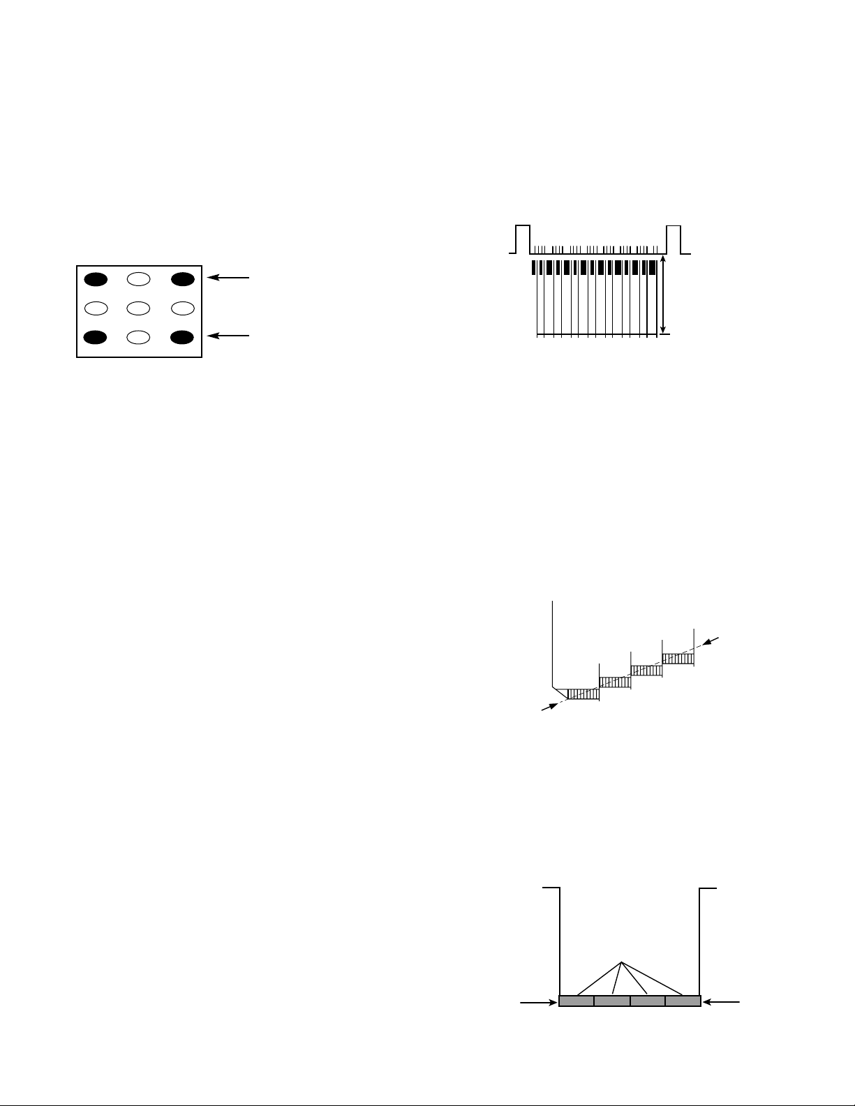
black to white level. (See Figure 2.)
CAUTION
FOR CONTINUED PROTECTION AGAINST
A RISK OF FIRE, REPLACE ONLY WITH THE
SAME TYPE 4A, 125V FUSE.
ATTENTION : POUR MAINTENIR LA PROTECTION CONTRE LES RISQUES
D’ INCENDIE UTILISER UN FUSIBLE DE
RECHANGE DE MEME TYPE 4A, 125V.
Figure 2.
4A 125V
1V
15 Vp-p
Page 15
— 15 —
Drive Level Adjustment
13. Select “Drive Level Adjustment” Menu (between
NO. 08E and NO. 0B0) with ▲ or ▼ key. The Menu display will appear.
14. Adjust Red and Blue Drive Levels alternately with 1, 3,
7, or 9 key to produce normal black and white picture in
highlight areas. The Drive Level adjustment data will be
written in the Service Menu No. 106 and 108 automatically. (See Figure 3.)
15. Check for proper grayscale at all brightness levels.
Note: If Grayscale Adjustment is made after picture tube
replacement, check Brightness Adjustment.
BRIGHTNESS LEVEL ADJUSTMENT
Note: Grayscale Adjustment and High Voltage Check must be
completed before attempting Brightness Level
Adjustment.
1. Connect a color-bar generator to the analog antenna
terminal.
2. Switch the generator to the 15 IRE flat pattern.
3. Reset the picture controls to the Sports level.
4. Connect voltmeter (high impedance) + lead to terminal
TP51 and – lead to terminal TP50 on P/D board. Set
voltmeter for 1.5V ~ 3V range.
5. Turn off the receiver and disconnect the AC power cord.
6. While pressing the VOLUME – key, reconnect the AC
power cord. The Service Menu display will now appear.
7. Select NO. 109 (SBR2: Sub Brightness, Bit 7 - 2) with ▲
or ▼ key.
8. Adjust the data with numeric keys
for 20mVDC.
9. Press the MENU key to turn off the Service Menu display.
10. Check brightness level on every active channel, readjust
(repeat steps 5 ~ 9), if necessary.
Note: Do not set to excessive brightness level, otherwise
the contrast level will be suppressed.
SUB CONTRAST ADJUSTMENT
1. Connect a color-bar generator to the analog antenna
terminal.
2. Switch the generator to the crosshatch pattern.
3. Connect oscilloscope probe (at least 50:1) to TP47G and
ground lead to TE47 on the CRT socket PWB.
4. Turn off the receiver and disconnect the AC power cord.
5. While pressing the VOLUME – key, reconnect the AC
power cord. The Service Menu display will now appear.
6. Select NO. 109 (SBR2: Sub Brightness, Bit 7 - 2) with ▲
or ▼ key. Remember this data setting.
7. Set the data with numeric key to 2E with numeric keys.
8. Select NO. 10D (SCO4: Sub Contrast, Bit 7 - 4) with
▲ or ▼ key.
9. Set the data with numeric keys 4 - 7 for 100Vp-p.
10. Reset brightness level to previous data (repeat steps
6 – 7). To turn off the Service Menu display, press the
MENU key.
SUB COLOR AND SUB HUE ADJUSTMENT
Sub Hue (Tint)
1. Connect a color-bar generator to the analog antenna
terminal. Set picture controls to Sports level.
2. Switch the generator to the color-bar (NTSC) pattern.
3. Connect oscilloscope probe (at least 50:1) to TP47G and
ground lead to TE47 on the CRT socket PWB.
4. Turn off the receiver and disconnect the AC power cord.
5. While pressing the VOLUME – key, reconnect the AC
power cord. The Service Menu display will now appear.
6. Select NO. 102 (SHU2: Sub HUE, Bit 7 - 2) with ▲ or ▼ key.
7. Set the data with numeric keys 2 - 7 for waveform
shown in Figure 5.
Sub Color
8. Select NO. 103 (SCL2: Sub Color, Bit 7 - 2) with ▲ or ▼ key.
9. Set the data with numeric keys 7 -2 for waveform
shown in Figure 6 (Flat Waveform).
10. After adjustment add 8 steps to NO. 102 (SHU2: Sub
HUE) data and 8 steps to NO. 103 (SCL2: Sub Color) data.
To turn off the Service Menu display, press the MENU
key.
1
2
3
4 5 6
7 98
RD(–)
RD(+)
BD(–)
BD(+)
(N/A)
(N/A)
(N/A)
(N/A)
(N/A)
Figure 3. Remote Control Number keys’ functions in
Service Menu “Drive Level Adjustment”
FOR RED DRIVE ADJUSTMENT
FOR BLUE DRIVE ADJUSTMENT
Figure 6. Sub Color
Figure 4. Sub Contrast
Figure 5. Sub Hue
100Vp-p
(From Blanking Level
to White 100IRE)
Same level
Page 16

— 16 —
SERVICE AD JUSTMENTS (Continued)
HIGH VOL T AGE HOLD-DOWN TEST
Every time the receiver is serviced, the HIGH VOLTAGE
HOLD-DOWN circuit must be tested for proper operation by
following these steps:
1. Connect receiver to 120V AC line. Tune receiver to active
channel. Reset the picture controls to the Sports level.
2. Check that the voltage measured between TP7 and TE7
(ground side) on the P/D PC board is within 20 VDC to 24
VDC. If the voltage is out of this range, the Hold-Down
Circuit must be checked.
3. Connect a DC Voltage supply to TP7 and TE7 through a
100 ohm 1/4W resistor. Adjust the DC voltage to 26 VDC.
The receiver should shut down, losing raster and sound.
Then the receiver should turn off automatically.
This reaction indicates that the Hold-Down circuit is functioning properly. If the receiver does not shutdown, a
malfunction is indicated and its cause must be found and
corrected.
4. To obtain picture again, remove the DC Supply and wait
a few minutes. Now turn on the receiver.
HIGH VOL T AGE CHECK
Note: +B (+140V) Voltage Check and Grayscale Adjustment
must be completed before attempting High Voltage
Check.
1. Connect high voltage voltmeter – lead to ground, and
connect + lead to anode of picture tube.
2. Tune receiver to an active channel and confirm TV is
operating properly.
3. Eliminate the beam current by adjusting the contrast and
brightness controls to minimum.
4. Confirm high voltage is within 28.2 KV and 32.9 KV. If
reading is not within range, check horizontal circuit.
No high-voltage adjustment is provided on this chassis.
FOCUS ADJUSTMENT
Adjust focus control (T402) for well defined scanning lines.
PURITY AND CONVERGENCE ADJUSTMENTS
Purity and Convergence have been aligned at the factory.
No re-alignment is necessary.
MULTI-SOUND SECTION ADJUSTMENTS
Note: Multi-Sound Section must be adjusted after
A101 (U/V Tuner), IC3601 (MTS Decoder), Digital
Module or IC802 (EEPROM) is replaced.
INPUT LEVEL ADJUSTMENT
1. Connect a signal to the analog antenna terminal with
audio of 1 KHZ 100% modulation.
2. Turn off the receiver and disconnect the AC power cord
(AC 120V line).
3. Connect voltmeter (RMS) to TP317 and ground on the
Main PC board.
4. While pressing the VOLUME – key, reconnect the AC
power cord. The Service Menu will now appear.
5. Select NO. 080 (ATT: MTS Input Level) with the ▲ or ▼
key.
6. Adjust the + or – key for a voltmeter reading of 400 ±
20 mVrms at TP317.
SEP ARA TION AD JUSTMENT
7. Turn off the receiver and disconnect the AC power cord
(AC 120V line).
8. Connect oscilloscope CH1 to TP317 and CH2 to TP318
and ground.
9. Connect an MTS TV/Stereo generator to antenna terminal.
10. While pressing the VOLUME – key, reconnect the AC
power cord. The Service Menu will now appear.
11. Select pilot, 300Hz audio frequency and Left modulating
signal.
12. Select NO. 081 (WDB: Wide Band) with the ▲ or ▼ key.
13. Adjust the + or – key for minimum low frequencies at
TP317. (See Figure 7.)
14. Select 4 KHz audio frequency and Right modulating signal.
15. Select NO. 082 (SPC: Spectral) with the ▲ or ▼ key.
16. Adjust the + or – key for minimum high frequencies at
TP318. (See Figure 7.)
Repeat adjustments (steps 11–16) until no further decreases
in amplitude can be obtained. Press the MENU key to turn
off the Service Menu display.
Figure 7. Separation Adjustments
Minimize L leakage
TP317 (R)
300Hz
Minimize R leakage
TP318 (L)
4KHz
Page 17

PINCUSHION CORRECTION ADJUSTMENT
1. Connect a color-bar generator to the analog antenna
terminal and select a crosshatch pattern.
2. Set the picture controls to the Sports level.
3. Turn off the receiver and disconnect the AC power cord
(AC 120V line).
4. While pressing the VOLUME – key, reconnect the AC
power cord. The Service Menu will now appear.
5. Select the items below with ▲ or ▼ key according to the
symptoms of Figure 8.
NO.ITEM Bit NAME
11A PAP2 7 - 2 Pin AMP
11D PPH2 7 - 2 Pin Phase
11F ABO2 7 - 2 AFC Bow
120 AAN2 7 - 2 AFC Angle
11B UCP2 7 - 2 Upper Corner Pin
11C LCP2 7 - 2 Lower Corner Pin
6. Adjust the data with numeric keys for straight vertical
lines. To turn off the Service Menu display, press the
MENU key.
OSD ADJUSTMENT
1. Connect a color-bar generator to the analog antenna
terminal.
2. Set the picture controls to the Sports level.
3. Turn off the receiver and disconnect the AC power cord.
(120V AC line)
4. While pressing the VOLUME – key, reconnect the AC
power cord. The Service Menu display will now appear.
5. Select NO. 089 (OSD: On-Screen Display) with ▲ or ▼
key.
6. Adjust the + or - key for proper position shown in
Figure 9. To turn off the Service Menu display, press the
MENU key.
COMPONENT Y LEVEL CONFIRM
1. Connect a color-bar generator to the analog antenna
terminal.
2. Switch the generator to the color-bar (NTSC) pattern.
3. Connect oscilloscope probe to Connector KG pin 12 and
ground on the main board.
4. Confirm a reading of 0.7 Vp-p ± .05. See Figure 10.
— 17 —
Figure 8. Pincushion Adjustments
Figure 9.
Figure 10.
Pin AMP
Visible
50mm
091
OSD 03
Area
00000011
Pin Phase
AFC Bow
AFC Angle
Upper Corner Pin
0.7 Vp-p
Lower Corner Pin
Page 18
— 18 —
SERVICE HINTS
POWER FAILURE DETECTOR
This unit is equipped with a Power Failure Detector function included in the CPU which checks for an abnormal condition in
the chassis power supplies, including the power supply derived from the Horizontal Output Transformer.
If, while the power is on, a failure is caused by any of the following that results in a low voltage supply, the CPU will turn the
unit off in 1.5 seconds to prevent further damage:
•
Failure within the power supply circuits.
•
A short circuit in the load side from the supply.
•
Stoppage of the Horizontal Output Oscillator caused by the X-Radiation protection Hold-Down Circuit.
If, while the power is off, the power is switched on and any of these failures remains uncorrected, the CPU will shut off the
power within three seconds.
Check the following if the unit is turned off by the power failure detector.
1. Disconnect the AC power cord (120V AC line) for at least 10 seconds.
2. Connect a DC Voltmeter to the circuits shown below.
3. Press the Power key and check for the proper voltage supplies.
4. If any of these voltages is low, the power failure detector should turn the unit off within three seconds.
5. Check all circuits shown above.
Note: This unit is equipped with a Power Surge Protection feature included in the CPU. If power failure occurs three times
within 15 minutes, the CPU will automatically stop functioning to help prevent secondary damage. (TV will not turn on
by pressing the power key.) To reset the operating programs within the CPU, disconnect the AC power cord for at least
10 seconds.
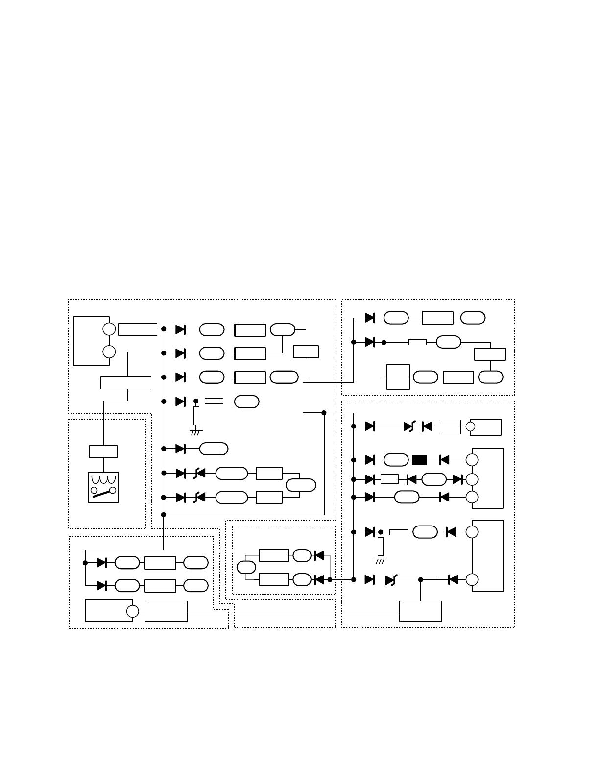
Block Diagram (Power Fail Lines)
IC801 (CPU)
14
39
Power ON/OFF
K9FRB (5)
Front
K1901 (5)
Q1611
RL601
(Main Relay)
Video
D2302
D2303
(CRT Driver)
IC2501
Q851/Q825
9V IC2303
5V IC2304
Hold Down
12
(Circuit)
D663
D662
D661
D664
D665
D654 D659
D676 D653
K8VBD (19)
K23VBD (19)
14V
6.5V
k23VDA (15)
5VTV 6.5V
5VIP
9VTV
R655
R655
R656
R656
31VTV
3.3VDM
2.5VDM
IC662
IC663
IC661
21V
14VTV
IC652
IC653
DAF
IC4304
14V
IC4305
Main
K8VDA (15)
Main
IC651
14VDM
12V
5V
K6PDB (8)
KG (6)
K6PDD (2)
D4365
D4366
K43B (9)
D1281
9V IC1281
D7103
K10G (6)
K4D (2)
D510
D622
D649
D652
D486 D481
D429 D482D428
K4DF (9)
K5B (8)
Q7101
D7102
D7101
21V
Q642
R488
R487
R7112
D509
D623
35V
Hold Down
(Circuit)
5V
2.5V IC7103
P/D
D508
Vertical
Output
D621
TJ7
D656
-15V
D631
200V
14V
IC7102
3.3V
(V Out)
3
IC501
(Switching)
15
T601
16
21
(FBT)
4
T402
9
AV
Page 19

— 19 —
MECHANICAL DISASSEMBLIES
CABINET BACK REMOVAL
1. Refer to Figure 1, remove 13 screws.
2. Pull off cabinet back and remove.
CHASSIS REMOVAL
1. Remove cabinet back.
2. Discharge the picture tube anode (2nd anode lead) to the
dag coating (picture tube grounding lead).
3.Disconnect degaussing coil socket (KD), picture tube
socket, deflection yoke connector (KX), speakers
connector (KSP), picture tube ground leads (2), velocity
modulation coil connector (K17A) and 2nd anode lead.
4. Remove chassis completely by sliding it straight back.
PICTURE TUBE REMOV AL
CAUTION: Do not disturb the deflection yoke or magnet
assembly on the picture tube neck. Care must be taken to
keep these assemblies intact, unless picture tube is being
replaced. Discharge the picture tube to the coating before
handling the tube.
1. Remove chassis, referring to Chassis Removal instructions.
2. Place cabinet’s front face down on a soft surface.
3. Remove the screw on each corner of the picture tube and
GENTLY lift the picture tube out of the cabinet.
4.Install a replacement picture tube in reverse order.
Properly install the degaussing coil and picture tube
grounding lead on the picture tube. See Figure 2.
Note: If Picture Tube is being replaced, mount the Degaussing
Coil properly on the tube. See Figure 2.
Figure 2. Picture Tube Removal
Figure 1. Cabinet Back Removal
DEGAUSSING
COIL
DEGAUSSING COIL
SOCKET
PICTURE TUBE
GROUNDING LEAD
TO PICTURE TUBE
SOCKET BOARD
GROUND
Page 20

— 20 —
CHASSIS ELECTRICAL PARTS LIST
CAPACITORS
NOTES:
Read description of the Capacitor as follows:
(Example)
CERAMIC 100P K 50V
Rated Voltage
Tolerance Symbols:
less than 10PF
A . .Not specified
B . .±0.1PF C . .±0.25PF
D . .±0.5PF F . .±1PF
G . .±2PF R . .+0.25 - 0PF
S . .+0 - 0.25PF E . .+0 - 1PF
more than 10PF
A . .Not specified
B . .±0.1% C . .±0.25%
D . .±0.5% F . .±1%
G . .±2% H . .±3%
J . .±5% K . .±10%
L . .±15% M . .±20%
N . .±30% P . .+100 - 0%
Q . .+30 - 10% T . .+50 - 10%
U . .+75 - 10% V . .+20 - 10%
W .+100 - 10% X . .+40 - 20%
Y . .+150 - 10% Z . .+80 - 20%
Rated Value: P...Pico Farad U...Micro Farad
Material:
CERAMIC . . . . . .Ceramic
MT-PAPER . . . . .Metalized Paper
POLYESTER . . .Polyester
MT-POLYEST . .Metalized Polyester
POLYPRO . . . . .Polypropylene
MT-POLYPRO . .Metalized Polypropylene
COMPO-FILM . .Composite Film
MT-COMPO . . . .Metalized Composite
STYRENE . . . . . .Styrene
TA-SOLID . . . . .Tantalum Solid
AL-SOLID . . . . . .Aluminum Solid
ELECT . . . . . . . .Electrolytic
NP-ELECT . . . . .Non-Polarized Electrolytic
OS-SOLID . . . . .Aluminum Solid with Organic
Semiconductive Electrolytic
CAUTION: To Protect against electrical shock and for continued product safety, refer to SAFETY PRECAUTIONS,
X-RADIATION PRECAUTIONS, HIGH VOLTAGE HOLD-DOWN TEST, and PRODUCT SAFETY NOTICE on Page 2.
Notes: Parts having Location Number are located on the following boards.
Numbers 400, 600, Series . . . . . . . . . . . . . . . . . . . . . .On the Main Board and Power / Deflection Board
Numbers 700 Series . . . . . . . . . . . . . . . . . . . . . . . . . . .On the Picture Tube Socket Board
Numbers 900 Series . . . . . . . . . . . . . . . . . . . . . . . . . . .Out of Board.
Numbers 1700 Series . . . . . . . . . . . . . . . . . . . . . . . . . .On the Velocity Modulation Board
Numbers 2000 Series . . . . . . . . . . . . . . . . . . . . . . . . . .On the Video Board
All Other Numbers . . . . . . . . . . . . . . . . . . . . . . . . . . .On the Main Board and AV Board
PRODUCT SAFETY NOTICE
PRODUCT SAFETY SHOULD BE CONSIDERED WHEN A REPLACEMENT IS MADE IN ANY AREA OF A RECEIVER.
COMPONENTS INDICATED BY A STAR (★) IN THIS PARTS LIST AND THE SCHEMATIC DIAGRAM DESIGNATE
COMPONENTS IN WHICH SAFETY CAN BE OF SPECIAL SIGNIFICANCE. IT IS PARTICULARLY RECOMMENDED
THAT ONLY PARTS DESIGNATED ON THE FOLLOWING PARTS LIST BE USED FOR COMPONENT REPLACEMENT
DESIGNATED B Y A STAR. NO DEVIATIONS FROM RESISTANCE,W ATTAGE,AND VOLTAGE RATINGS MAY BE MADE
FOR REPLACEMENT ITEMS DESIGNATED BY A STAR.
Note: Schematic part location numbers may not always match with the part descriptions.
The part descriptions are correct and should be used.
RESISTORS
NOTES:
Read description of the Resistor as follows:
(Example)
CARBON 4.7K J A 1/4W
Rated Wattage
Performance Symbols:
A...General B...Non-flammable
Z...Low noise
Other... Temperature coefficient
Tolerance Symbols:
A...0.05% B...0.1% C...25%
D...0.5% F...1% G...2%
J...5% K...10% M...20%
P...+5 -15%
Rated Value, ohms:
K...1,000 M...1,000,000
Material:
CARBON .............
MT-FILM ..............
OXIDE-MT ...........
SOLID ..................
MT-GLAZE ...........
WIRE WOUND .....
CERAMIC RES ....
FUSIBLE RES .....
Carbon
Metal Film
Oxide Metal Film
Composition
Metal Glaze
Wire Wound
Ceramic
Fusible
Page 21

— 21 —
Schematic
Location
Part No.
Description
Schematic
Location
Part No.
Description
MAIN PC BOARD
CAPACITORS
C100 403 224 6108 CERAMIC 0.01U K 50V
C101 404 084 2408 ELECT 470U M 6.3V
C102 403 224 6108 CERAMIC 0.01U K 50V
C103 403 235 6203 CERAMIC 0.01U Z 50V
C105 404 084 4303 ELECT 47U M 50V
C106 403 224 6108 CERAMIC 0.01U K 50V
C489 404 084 3306 ELECT 470U M 16V
C646 404 084 3405 ELECT 1000U M 25V
C648 403 279 0106 CERAMIC 0.1U Z 25V
C650 404 084 3405 ELECT 1000U M 25V
C651 403 279 0106 CERAMIC 0.1U Z 25V
C652 404 084 3405 ELECT 1000U M 25V
C653 404 087 1804 ELECT 1000U M 10V
C654 403 260 2003 MT-COMPO 1U J 50V
C655 403 279 0106 CERAMIC 0.1U Z 25V
C658 404 087 1804 ELECT 1000U M 10V
C659 403 260 2003 MT-COMPO 1U J 50V
C660 404 087 1804 ELECT 1000U M 10V
C661 404 084 2804 ELECT 100U M 16V
C662 404 084 2804 ELECT 100U M 16V
C663 403 279 0106 CERAMIC 0.1U Z 25V
C664 404 084 2804 ELECT 100U M 16V
C665 404 084 2804 ELECT 100U M 16V
C666 403 279 0106 CERAMIC 0.1U Z 25V
C671 404 084 2804 ELECT 100U M 16V
C672 403 260 2003 MT-COMPO 1U J 50V
C801 403 224 5507 CERAMIC 22P J 50V
C802 403 224 5507 CERAMIC 22P J 50V
C804 403 235 6203 CERAMIC 0.01U Z 50V
C806 403 235 6203 CERAMIC 0.01U Z 50V
C814 403 235 6203 CERAMIC 0.01U Z 50V
C816 403 235 0003 CERAMIC 33P J 50V
C818 403 224 5507 CERAMIC 22P J 50V
C821 403 224 5507 CERAMIC 22P J 50V
C822 404 084 2408 ELECT 470U M 6.3V
C823 403 235 6203 CERAMIC 0.01U Z 50V
C824 404 084 3801 ELECT 1U M 50V
C825 403 224 5705 CERAMIC 1000P K 50V
C826 403 235 0706 CERAMIC 120P J 50V
C827 403 235 6203 CERAMIC 0.01U Z 50V
C829 403 235 6203 CERAMIC 0.01U Z 50V
C832 403 224 5507 CERAMIC 22P J 50V
C833 403 235 0300 CERAMIC 56P J 50V
C834 403 235 0300 CERAMIC 56P J 50V
C835 403 235 0300 CERAMIC 56P J 50V
C836 403 235 0300 CERAMIC 56P J 50V
C837 403 235 4605 CERAMIC 270P K 50V
C840 403 224 5507 CERAMIC 22P J 50V
C841 403 224 5507 CERAMIC 22P J 50V
C842 403 224 5507 CERAMIC 22P J 50V
C844 403 224 5804 CERAMIC 2200P K 50V
C852 403 235 1000 CERAMIC 220P J 50V
C854 403 155 4600 CERAMIC 4P C 50V
C855 403 155 4600 CERAMIC 4P C 50V
C856 403 155 4600 CERAMIC 4P C 50V
C862 403 235 6203 CERAMIC 0.01U Z 50V
C863 404 084 3801 ELECT 1U M 50V
C864 403 235 6203 CERAMIC 0.01U Z 50V
C865 404 084 2507 ELECT 47U M 10V
C866 404 084 3801 ELECT 1U M 50V
C867 403 235 6203 CERAMIC 0.01U Z 50V
C871 403 279 0106 CERAMIC 0.1U Z 25V
C1261 403 279 0106 CERAMIC 0.1U Z 25V
C1262 404 084 3207 ELECT 47U M 16V
C1263 403 279 0106 CERAMIC 0.1U Z 25V
C1264 403 279 0106 CERAMIC 0.1U Z 25V
C1265 403 279 0106 CERAMIC 0.1U Z 25V
C1266 404 085 5606 NP-ELECT 22U M 16V
C1267 404 085 5606 NP-ELECT 22U M 16V
C1268 404 085 5606 NP-ELECT 22U M 16V
C1269 404 084 2804 ELECT 100U M 16V
C1270 404 085 5606 NP-ELECT 22U M 16V
C1273 404 085 5606 NP-ELECT 22U M 16V
C1276 404 085 5606 NP-ELECT 22U M 16V
C1279 404 088 5702 ELECT 22U M 16V
C1292 404 088 5702 ELECT 22U M 16V
C1293 404 088 5702 ELECT 22U M 16V
C1294 404 088 5702 ELECT 22U M 16V
C1815 403 279 0106 CERAMIC 0.1U Z 25V
C1851 404 084 3207 ELECT 47U M 16V
C1852 403 279 0106 CERAMIC 0.1U Z 25V
C1853 403 235 0607 CERAMIC 100P J 50V
C1854 403 235 0607 CERAMIC 100P J 50V
C1855 403 235 0904 CERAMIC 180P J 50V
C1857 403 235 1406 CERAMIC 470P J 50V
C2801 403 279 0106 CERAMIC 0.1U Z 25V
C2802 403 279 0106 CERAMIC 0.1U Z 25V
C2803 403 279 0106 CERAMIC 0.1U Z 25V
C2804 403 279 0106 CERAMIC 0.1U Z 25V
C2806 404 084 4006 ELECT 2.2U M 50V
C2807 403 224 6108 CERAMIC 0.01U K 50V
C2810 404 084 2804 ELECT 100U M 16V
C2811 403 279 0106 CERAMIC 0.1U Z 25V
C2812 404 084 2804 ELECT 100U M 16V
C2813 403 279 0106 CERAMIC 0.1U Z 25V
C2814 403 279 0106 CERAMIC 0.1U Z 25V
C2825 404 084 3801 ELECT 1U M 50V
C2827 404 084 3801 ELECT 1U M 50V
C2902 404 084 2705 ELECT 10U M 16V
C2904 404 084 2705 ELECT 10U M 16V
C2905 403 279 0106 CERAMIC 0.1U Z 25V
C2907 404 084 2705 ELECT 10U M 16V
C2908 404 084 2804 ELECT 100U M 16V
C2914 403 279 0106 CERAMIC 0.1U Z 25V
C2940 404 084 2705 ELECT 10U M 16V
C2943 404 084 2705 ELECT 10U M 16V
C2945 404 084 2705 ELECT 10U M 16V
C2950 403 279 0106 CERAMIC 0.1U Z 25V
C2951 404 084 2804 ELECT 100U M 16V
C2952 404 085 5606 NP-ELECT 22U M 16V
C2954 404 085 5606 NP-ELECT 22U M 16V
C2956 404 085 5606 NP-ELECT 22U M 16V
C3243 404 087 1200 ELECT 0.1U M 50V
C3401 404 089 6500 NP-ELECT 4.7U M 50V
C3402 404 084 3801 ELECT 1U M 50V
Page 22

— 22 —
C3403 404 084 3801 ELECT 1U M 50V
C3404 404 084 3801 ELECT 1U M 50V
C3406 403 343 4603 CERAMIC 0.022U K 50V
C3407 403 224 5804 CERAMIC 2200P K 50V
C3408 404 087 1200 ELECT 0.1U M 50V
C3409 404 084 4204 ELECT 4.7U M 50V
C3410 404 084 3900 ELECT 10U M 50V
C3411 404 084 3801 ELECT 1U M 50V
C3412 404 084 3801 ELECT 1U M 50V
C3415 404 084 2903 ELECT 1 000U M 16V
C3416 404 084 3306 ELECT 470U M 16V
C3417 404 084 3801 ELECT 1U M 50V
C3418 404 084 3801 ELECT 1U M 50V
C3419 404 084 3801 ELECT 1U M 50V
C3420 404 084 5607 MT-POLYEST 0.33UJ 63V
C3420 403 260 2904 MT-COMPO 0.33U J 50V
C3421 404 084 3900 ELECT 10U M 50V
C3422 404 084 4204 ELECT 4.7U M 50V
C3424 403 224 5804 CERAMIC 2200P K 50V
C3425 404 084 3801 ELECT 1U M 50V
C3427 404 084 3801 ELECT 1U M 50V
C3428 404 084 3801 ELECT 1U M 50V
C3429 404 084 3801 ELECT 1U M 50V
C3430 404 089 6500 NP-ELECT 4.7U M 50V
C3435 404 091 6604 ELECT 4.7U M 25V
C3437 404 091 6604 ELECT 4.7U M 25V
C3606 404 089 6500 NP-ELECT 4.7U M 50V
C3608 403 235 5701 CERAMIC 5600P K 50V
C3609 403 325 2504 CERAMIC 0.012U K 50V
C3610 404 084 3702 ELECT 0 .47U M 50V
C3611 404 084 3702 ELECT 0 .47U M 50V
C3612 404 084 3207 ELECT 47U M 16V
C3613 403 235 1307 CERAMIC 390P J 50V
C3615 404 091 6604 ELECT 4.7U M 25V
C3616 404 084 3306 ELECT 470U M 16V
C3617 404 089 6500 NP-ELECT 4.7U M 50V
C3618 404 084 2903 ELECT 1000U M 16V
C3619 404 091 6604 ELECT 4.7U M 25V
C3620 404 089 6500 NP-ELECT 4.7U M 50V
C3622 403 224 5606 CERAMIC 2700P K 50V
C3623 403 323 3602 CERAMIC 0.047U K 50V
C3624 403 342 9203 TA-SOLID 3.3U K 10V
C3626 404 089 6500 NP-ELECT 4.7U M 50V
C3627 403 299 1820 TA-SOLID 10U K 10V
C3628 404 084 3801 ELECT 1U M 50V
C3629 404 089 6500 NP-ELECT 4.7U M 50V
C3630 404 089 6500 NP-ELECT 4.7U M 50V
C3631 404 085 5606 NP-ELECT 22U M 16V
C5506 403 279 0106 CERAMIC 0.1U Z 25V
C5507 404 084 3801 ELECT 1U M 50V
DIODES
D101 407 221 7106 ZENER DIODE UDZS-TE-1712B
D651 407 223 5209 DIODE RK46 015-304
D653 407 224 4706 ZENER DIODE 02DZ3.0Z(TPH3
D654 407 012 4406 DIODE 1SS133
D655 407 223 5209 DIODE RK46 015-304
D659 407 224 4706 ZENER DIODE 02DZ3.0Z(TPH3
D661 407 012 4406 DIODE 1SS133
D663 407 012 4406 DIODE 1SS133
D664 407 012 4406 DIODE 1SS133
D665 407 012 4406 DIODE 1SS133
D672 407 223 5209 DIODE RK46 015-304
D676 407 012 4406 DIODE 1SS133
D801 407 206 5608 ZENER DIODE UDZS10B TE-17
D805 407 206 5608 ZENER DIODE UDZS10B TE-17
D809 407 206 5608 ZENER DIODE UDZS10B TE-17
D810 407 206 5608 ZENER DIODE UDZS10B TE-17
D812 407 206 6308 ZENER DIODE UDZS5.1B TE-17
D816 407 206 5608 ZENER DIODE UDZS10B TE-17
D822 407 206 5608 ZENER DIODE UDZS10B TE-17
D825 407 206 5608 ZENER DIODE UDZS10B TE-17
D826 407 149 0807 DIODE 1SS355 TE-17
D827 407 206 5608 ZENER DIODE UDZS10B TE-17
D828 407 206 5608 ZENER DIODE UDZS10B TE-17
D835 407 221 7106 ZENER DIODE UDZS-TE-1712B
D836 407 221 7106 ZENER DIODE UDZS-TE-1712B
D837 407 206 5608 ZENER DIODE UDZS10B TE-17
D838 407 206 5608 ZENER DIODE UDZS10B TE-17
D839 407 206 5608 ZENER DIODE UDZS10B TE-17
D840 407 206 5608 ZENER DIODE UDZS10B TE-17
D841 407 206 5608 ZENER DIODE UDZS10B TE-17
D842 407 206 5608 ZENER DIODE UDZS10B TE-17
D857 407 209 1201 ZENER DIODE UDZS6.2B TE-17
D858 407 012 4406 DIODE 1SS133
D871 407 206 5608 ZENER DIODE UDZS10B TE-17
D896 407 206 5608 ZENER DIODE UDZS10B TE-17
D897 407 206 5608 ZENER DIODE UDZS10B TE-17
D898 407 206 5608 ZENER DIODE UDZS10B TE-17
D899 407 206 5608 ZENER DIODE UDZS10B TE-17
D1280 407 012 4406 DIODE 1SS133
D1282 407 012 4406 DIODE 1SS133
D3401 407 092 9526 DIODE SB07-03C-TB
D3413 407 206 5608 ZENER DIODE UDZS10B TE-17
D3414 407 206 5608 ZENER DIODE UDZS10B TE-17
D3416 407 221 7106 ZENER DIODE UDZS-TE-1712B
D3617 407 092 9526 DIODE SB07-03C-TB
INTEGRATED CIRCUITS
IC651 410 401 0002 IC SI-8050SS LF1113
IC652 409 503 7507 IC PQ1CG3032FZ
IC653 409 503 7507 IC PQ1CG3032FZ
IC661 410 401 0101 IC SI-3090FA LF1113
IC662 410 330 6007 IC SI-3050FA LF1113
IC801 410 495 8106 IC M37151M*-***FP
IC802 409 301 2803 IC MN1381-Q
IC803 409 495 7103 IC CAT24WC08P
409 383 6805 IC 24LC08B/P
IC804 409 400 2704 IC TC7SET08F-TE85L
IC1261 409 444 4722 IC NJM2534M-TE2
IC1262 409 444 4722 IC NJM2534M-TE2
IC1263 409 444 4722 IC NJM2534M-TE2
IC1264 409 264 6009 IC NJM2268M
IC1851 409 223 1809 IC MC74HC04AF
IC2801 409 523 5002 IC TA1318AF
IC2903 409 051 2722 IC TC4052BF-EL
IC3401 409 564 4309 IC NJW1142M
IC3601 409 572 2205 IC CXA2104S
IC5506 409 074 9623 IC M51957BFP
Schematic
Location
Part No.
Description
Schematic
Location
Part No.
Description
Page 23

— 23 —
COILS
L001 645 008 2894 INDUCTOR, 5.6U K
645 016 3104 INDUCTOR, 5.6U K
L101 645 008 2894 INDUCTOR, 5.6U K
645 016 3104 INDUCTOR, 5.6U K
L651 645 045 9436 INDUCTOR, 330U K
L652 645 049 3751 INDUCTOR, 47UH K
L653 645 047 6655 INDUCTOR, 33U K
L654 645 047 6655 INDUCTOR, 33U K
L661 645 049 3751 INDUCTOR, 47UH K
L801 645 008 2894 INDUCTOR, 5.6U K
645 016 3104 INDUCTOR, 5.6U K
L802 645 008 2894 INDUCTOR, 5.6U K
645 016 3104 INDUCTOR, 5.6U K
L803 645 008 2894 INDUCTOR, 5.6U K
645 016 3104 INDUCTOR, 5.6U K
L804 645 008 2894 INDUCTOR, 5.6U K
645 016 3104 INDUCTOR, 5.6U K
L811 645 006 2490 INDUCTOR, 1U K
645 016 2411 INDUCTOR, 1U K
L837 645 006 2490 INDUCTOR, 1U K
645 016 2411 INDUCTOR, 1U K
L1851 645 008 2894 INDUCTOR, 5.6U K
645 016 3104 INDUCTOR, 5.6U K
TRANSISTORS
Q825 405 134 5925 TR 2SA1037AK T146 R
405 147 2205 TR 2SA1037AK T146 S
405 002 0308 TR 2SA1037K-T-96-R
405 002 0407 TR 2SA1037K-T-96-S
405 002 6726 TR 2SA1179-M6
405 002 6924 TR 2SA1179-M7-TB
405 163 1503 TR 2SA1179N-M6-TB
405 163 2708 TR 2SA1179N-M7-TB
405 173 9605 TR 2SA1235A1E
405 173 9704 TR 2SA1235A1F
Q851 405 014 4509 TR 2SC2412K-T-96-R
405 014 4608 TR 2SC2412K-T-96-S
405 015 8724 TR 2SC2812-L6-TB
405 015 8922 TR 2SC2812-L7-TB
405 163 1602 TR 2SC2812N-L6-TB
405 163 1701 TR 2SC2812N-L7-TB
405 173 9803 TR 2SC3928A1R
405 173 9902 TR 2SC3928A1S
Q1280 405 014 4509 TR 2SC2412K-T-96-R
405 014 4608 TR 2SC2412K-T-96-S
405 015 8724 TR 2SC2812-L6-TB
405 015 8922 TR 2SC2812-L7-TB
405 163 1602 TR 2SC2812N-L6-TB
405 163 1701 TR 2SC2812N-L7-TB
405 173 9803 TR 2SC3928A1R
405 173 9902 TR 2SC3928A1S
Q1281 405 014 4509 TR 2SC2412K-T-96-R
405 014 4608 TR 2SC2412K-T-96-S
405 015 8724 TR 2SC2812-L6-TB
405 015 8922 TR 2SC2812-L7-TB
405 163 1602 TR 2SC2812N-L6-TB
405 163 1701 TR 2SC2812N-L7-TB
405 173 9803 TR 2SC3928A1R
405 173 9902 TR 2SC3928A1S
Q1293 405 014 4509 TR 2SC2412K-T-96-R
405 014 4608 TR 2SC2412K-T-96-S
405 015 8724 TR 2SC2812-L6-TB
405 015 8922 TR 2SC2812-L7-TB
405 163 1602 TR 2SC2812N-L6-TB
405 163 1701 TR 2SC2812N-L7-TB
405 173 9803 TR 2SC3928A1R
405 173 9902 TR 2SC3928A1S
Q1295 405 014 4509 TR 2SC2412K-T-96-R
405 014 4608 TR 2SC2412K-T-96-S
405 015 8724 TR 2SC2812-L6-TB
405 015 8922 TR 2SC2812-L7-TB
405 163 1602 TR 2SC2812N-L6-TB
405 163 1701 TR 2SC2812N-L7-TB
405 173 9803 TR 2SC3928A1R
405 173 9902 TR 2SC3928A1S
Q1297 405 014 4509 TR 2SC2412K-T-96-R
405 014 4608 TR 2SC2412K-T-96-S
405 015 8724 TR 2SC2812-L6-TB
405 015 8922 TR 2SC2812-L7-TB
405 163 1602 TR 2SC2812N-L6-TB
405 163 1701 TR 2SC2812N-L7-TB
405 173 9803 TR 2SC3928A1R
405 173 9902 TR 2SC3928A1S
Q2902 405 014 4509 TR 2SC2412K-T-96-R
405 014 4608 TR 2SC2412K-T-96-S
405 015 8724 TR 2SC2812-L6-TB
405 015 8922 TR 2SC2812-L7-TB
405 163 1602 TR 2SC2812N-L6-TB
405 163 1701 TR 2SC2812N-L7-TB
405 173 9803 TR 2SC3928A1R
405 173 9902 TR 2SC3928A1S
Q2903 405 014 4509 TR 2SC2412K-T-96-R
405 014 4608 TR 2SC2412K-T-96-S
405 015 8724 TR 2SC2812-L6-TB
405 015 8922 TR 2SC2812-L7-TB
405 163 1602 TR 2SC2812N-L6-TB
405 163 1701 TR 2SC2812N-L7-TB
405 173 9803 TR 2SC3928A1R
405 173 9902 TR 2SC3928A1S
Q2904 405 014 4509 TR 2SC2412K-T-96-R
405 014 4608 TR 2SC2412K-T-96-S
405 015 8724 TR 2SC2812-L6-TB
405 015 8922 TR 2SC2812-L7-TB
405 163 1602 TR 2SC2812N-L6-TB
405 163 1701 TR 2SC2812N-L7-TB
405 173 9803 TR 2SC3928A1R
405 173 9902 TR 2SC3928A1S
Q2906 405 014 4509 TR 2SC2412K-T-96-R
405 014 4608 TR 2SC2412K-T-96-S
405 015 8724 TR 2SC2812-L6-TB
405 015 8922 TR 2SC2812-L7-TB
405 163 1602 TR 2SC2812N-L6-TB
405 163 1701 TR 2SC2812N-L7-TB
405 173 9803 TR 2SC3928A1R
405 173 9902 TR 2SC3928A1S
Q2910 405 014 4509 TR 2SC2412K-T-96-R
405 014 4608 TR 2SC2412K-T-96-S
405 015 8724 TR 2SC2812-L6-TB
405 015 8922 TR 2SC2812-L7-TB
Schematic
Location
Part No.
Description
Schematic
Location
Part No.
Description
Page 24

— 24 —
Q2910 (Cont.)405 163 1602 TR 2SC2812N-L6-TB
405 163 1701 TR 2SC2812N-L7-TB
405 173 9803 TR 2SC3928A1R
405 173 9902 TR 2SC3928A1S
Q2942 405 014 4509 TR 2SC2412K-T-96-R
405 014 4608 TR 2SC2412K-T-96-S
405 015 8724 TR 2SC2812-L6-TB
405 015 8922 TR 2SC2812-L7-TB
405 163 1602 TR 2SC2812N-L6-TB
405 163 1701 TR 2SC2812N-L7-TB
405 173 9803 TR 2SC3928A1R
405 173 9902 TR 2SC3928A1S
Q2943 405 014 4509 TR 2SC2412K-T-96-R
405 014 4608 TR 2SC2412K-T-96-S
405 015 8724 TR 2SC2812-L6-TB
405 015 8922 TR 2SC2812-L7-TB
405 163 1602 TR 2SC2812N-L6-TB
405 163 1701 TR 2SC2812N-L7-TB
405 173 9803 TR 2SC3928A1R
405 173 9902 TR 2SC3928A1S
Q2950 405 014 4509 TR 2SC2412K-T-96-R
405 014 4608 TR 2SC2412K-T-96-S
405 015 8724 TR 2SC2812-L6-TB
405 015 8922 TR 2SC2812-L7-TB
405 163 1602 TR 2SC2812N-L6-TB
405 163 1701 TR 2SC2812N-L7-TB
405 173 9803 TR 2SC3928A1R
405 173 9902 TR 2SC3928A1S
Q3410 405 014 4509 TR 2SC2412K-T-96-R
405 014 4608 TR 2SC2412K-T-96-S
405 015 8724 TR 2SC2812-L6-TB
405 015 8922 TR 2SC2812-L7-TB
405 163 1602 TR 2SC2812N-L6-TB
405 163 1701 TR 2SC2812N-L7-TB
405 173 9803 TR 2SC3928A1R
405 173 9902 TR 2SC3928A1S
Q3420 405 014 4509 TR 2SC2412K-T-96-R
405 014 4608 TR 2SC2412K-T-96-S
405 015 8724 TR 2SC2812-L6-TB
405 015 8922 TR 2SC2812-L7-TB
405 163 1602 TR 2SC2812N-L6-TB
405 163 1701 TR 2SC2812N-L7-TB
405 173 9803 TR 2SC3928A1R
405 173 9902 TR 2SC3928A1S
Q3457 405 014 4509 TR 2SC2412K-T-96-R
405 014 4608 TR 2SC2412K-T-96-S
405 015 8724 TR 2SC2812-L6-TB
405 015 8922 TR 2SC2812-L7-TB
405 163 1602 TR 2SC2812N-L6-TB
405 163 1701 TR 2SC2812N-L7-TB
405 173 9803 TR 2SC3928A1R
405 173 9902 TR 2SC3928A1S
Q3459 405 014 4509 TR 2SC2412K-T-96-R
405 014 4608 TR 2SC2412K-T-96-S
405 015 8724 TR 2SC2812-L6-TB
405 015 8922 TR 2SC2812-L7-TB
405 163 1602 TR 2SC2812N-L6-TB
405 163 1701 TR 2SC2812N-L7-TB
405 173 9803 TR 2SC3928A1R
405 173 9902 TR 2SC3928A1S
Q5501 405 014 4509 TR 2SC2412K-T-96-R
405 014 4608 TR 2SC2412K-T-96-S
405 015 8724 TR 2SC2812-L6-TB
405 015 8922 TR 2SC2812-L7-TB
405 163 1602 TR 2SC2812N-L6-TB
405 163 1701 TR 2SC2812N-L7-TB
405 173 9803 TR 2SC3928A1R
405 173 9902 TR 2SC3928A1S
Q5502 405 014 4509 TR 2SC2412K-T-96-R
405 014 4608 TR 2SC2412K-T-96-S
405 015 8724 TR 2SC2812-L6-TB
405 015 8922 TR 2SC2812-L7-TB
405 163 1602 TR 2SC2812N-L6-TB
405 163 1701 TR 2SC2812N-L7-TB
405 173 9803 TR 2SC3928A1R
405 173 9902 TR 2SC3928A1S
RESISTORS
R101 401 024 6700 CARBON 100 JA 1/6W
R102 401 024 6700 CARBON 100 JA 1/6W
R103 401 026 0607 CARBON 270 JA 1/6W
R104 401 026 9907 CARBON 4.7K JA 1/6W
R106 401 024 6700 CARBON 100 JA 1/6W
R634 401 256 6905 MT-GLAZE 680 JA 1/10W
R650 401 256 6905 MT-GLAZE 680 JA 1/10W
R651 401 256 2907 MT-GLAZE 150 JA 1/10W
R652 401 162 4002 MT-GLAZE 560 JA 1/10W
R653 401 162 2404 MT-GLAZE 1.2K JA 1/10W
R654 401 256 3706 MT-GLAZE 750 JA 1/10W
R655 401 162 3104 MT-GLAZE 3.3K JA 1/10W
R656 401 150 6100 MT-GLAZE 2.2K JA 1/10W
R659 401 150 6001 MT-GLAZE 0.000 ZA 1/10W
★ R663 401 069 0404 OXIDE-MT 6.8 JA 2W
R665 401 150 6209 MT-GLAZE 1K JA 1/10W
★ R666 401 111 3100 OXIDE-MT 0.82 JA 2W
R676 401 150 6209 MT-GLAZE 1K JA 1/10W
R801 401 162 4101 MT-GLAZE 5.6K JA 1/10W
R802 401 150 5905 MT-GLAZE 10K JA 1/10W
R803 401 150 6001 MT-GLAZE 0.000 ZA 1/10W
R804 401 255 6500 MT-GLAZE 100 JA 1/10W
R805 401 024 6700 CARBON 100 JA 1/6W
R806 401 255 6500 MT-GLAZE 100 JA 1/10W
R807 401 024 6700 CARBON 100 JA 1/6W
R809 401 024 6700 CARBON 100 JA 1/6W
R810 401 162 3708 MT-GLAZE 4.7K JA 1/10W
R811 401 150 5905 MT-GLAZE 10K JA 1/10W
R812 401 024 7004 CARBON 1K JA 1/6W
R814 401 255 6500 MT-GLAZE 100 JA 1/10W
R815 401 150 6209 MT-GLAZE 1K JA 1/10W
R816 401 024 6700 CARBON 100 JA 1/6W
R817 401 024 6700 CARBON 100 JA 1/6W
R823 401 150 5905 MT-GLAZE 10K JA 1/10W
R824 401 024 7004 CARBON 1K JA 1/6W
R826 401 025 7805 CARBON 2.2K JA 1/6W
R827 401 255 6500 MT-GLAZE 100 JA 1/10W
R828 401 150 5905 MT-GLAZE 10K JA 1/10W
R829 401 255 6500 MT-GLAZE 100 JA 1/10W
R830 401 150 5806 MT-GLAZE 100K JA 1/10W
R831 401 150 5806 MT-GLAZE 100K JA 1/10W
Schematic
Location
Part No.
Description
Schematic
Location
Part No.
Description
Page 25

— 25 —
R833 401 256 3805 MT-GLAZE 1.5K JA 1/10W
R834 401 162 3708 MT-GLAZE 4.7K JA 1/10W
R835 401 162 3708 MT-GLAZE 4.7K JA 1/10W
R836 401 162 3708 MT-GLAZE 4.7K JA 1/10W
R837 401 024 7400 CARBON 10K JA 1/6W
R838 401 024 6700 CARBON 100 JA 1/6W
R839 401 162 3708 MT-GLAZE 4.7K JA 1/10W
R840 401 150 5905 MT-GLAZE 10K JA 1/10W
R841 401 162 4101 MT-GLAZE 5.6K JA 1/10W
R842 401 150 5905 MT-GLAZE 10K JA 1/10W
R843 401 024 6700 CARBON 100 JA 1/6W
R844 401 024 6700 CARBON 100 JA 1/6W
R845 401 024 6700 CARBON 100 JA 1/6W
R846 401 162 3708 MT-GLAZE 4.7K JA 1/10W
R849 401 162 3708 MT-GLAZE 4.7K JA 1/10W
R851 401 150 5905 MT-GLAZE 10K JA 1/10W
R852 401 256 6301 MT-GLAZE 47K JA 1/10W
R853 401 256 6301 MT-GLAZE 47K JA 1/10W
R854 401 162 3708 MT-GLAZE 4.7K JA 1/10W
R855 401 162 4101 MT-GLAZE 5.6K JA 1/10W
R856 401 162 4101 MT-GLAZE 5.6K JA 1/10W
R866 401 255 6005 MT-GLAZE 1M JA 1/10W
R876 401 024 7004 CARBON 1K JA 1/6W
R880 401 256 7308 MT-GLAZE 6.8K JA 1/10W
R881 401 256 7308 MT-GLAZE 6.8K JA 1/10W
R883 401 256 7308 MT-GLAZE 6.8K JA 1/10W
R886 401 150 5905 MT-GLAZE 10K JA 1/10W
R887 401 150 5905 MT-GLAZE 10K JA 1/10W
R894 401 150 6209 MT-GLAZE 1K JA 1/10W
R895 401 024 7004 CARBON 1K JA 1/6W
R896 401 024 6700 CARBON 100 JA 1/6W
R897 401 024 6700 CARBON 100 JA 1/6W
R898 401 024 6700 CARBON 100 JA 1/6W
R899 401 024 6700 CARBON 100 JA 1/6W
R1262 401 256 2709 MT-GLAZE 75 JA 1/10W
R1263 401 027 6608 CARBON 75 JA 1/6W
R1264 401 024 7004 CARBON 1K JA 1/6W
R1265 401 256 2709 MT-GLAZE 75 JA 1/10W
R1266 401 027 6608 CARBON 75 JA 1/6W
R1267 401 256 1702 MT-GLAZE 33K JA 1/10W
R1268 401 256 2709 MT-GLAZE 75 JA 1/10W
R1269 401 027 6608 CARBON 75 JA 1/6W
R1270 401 024 6700 CARBON 100 JA 1/6W
R1271 401 024 6700 CARBON 100 JA 1/6W
R1272 401 024 6700 CARBON 100 JA 1/6W
R1279 401 150 6209 MT-GLAZE 1K JA 1/10W
R1280 401 256 4109 MT-GLAZE 56 JA 1/10W
R1281 401 256 6301 MT-GLAZE 47K JA 1/10W
R1282 401 150 5905 MT-GLAZE 10K JA 1/10W
R1283 401 162 3005 MT-GLAZE 22K JA 1/10W
R1284 401 024 7400 CARBON 10K JA 1/6W
R1285 401 256 1702 MT-GLAZE 33K JA 1/10W
R1286 401 256 7209 MT-GLAZE 18K JA 1/10W
R1287 401 256 1702 MT-GLAZE 33K JA 1/10W
R1288 401 256 4109 MT-GLAZE 56 JA 1/10W
R1289 401 256 7209 MT-GLAZE 18K JA 1/10W
R1290 401 256 1702 MT-GLAZE 33K JA 1/10W
R1291 401 256 4109 MT-GLAZE 56 JA 1/10W
R1294 401 256 4109 MT-GLAZE 56 JA 1/10W
R1295 401 150 6209 MT-GLAZE 1K JA 1/10W
R1296 401 256 7209 MT-GLAZE 18K JA 1/10W
R1297 401 256 4109 MT-GLAZE 56 JA 1/10W
R1298 401 150 6209 MT-GLAZE 1K JA 1/10W
R1299 401 256 4109 MT-GLAZE 56 JA 1/10W
R1851 401 025 4606 CARBON 18K JA 1/6W
R1852 401 162 3104 MT-GLAZE 3.3K JA 1/10W
R1855 401 256 3607 MT-GLAZE 15K JA 1/10W
R1856 401 256 7209 MT-GLAZE 18K JA 1/10W
R1857 401 256 6608 MT-GLAZE 68K JA 1/10W
R2807 401 162 4101 MT-GLAZE 5.6K JA 1/10W
R2809 401 256 4901 MT-GLAZE 360 JA 1/10W
R2811 401 150 6001 MT-GLAZE 0.000 ZA 1/10W
R2815 401 024 6700 CARBON 100 JA 1/6W
R2816 401 150 5905 MT-GLAZE 10K JA 1/10W
R2819 401 150 5905 MT-GLAZE 10K JA 1/10W
R2820 401 024 6700 CARBON 100 JA 1/6W
R2821 401 255 6500 MT-GLAZE 100 JA 1/10W
R2822 401 255 6500 MT-GLAZE 100 JA 1/10W
R2824 401 150 6001 MT-GLAZE 0.000 ZA 1/10W
R2827 401 024 6700 CARBON 100 JA 1/6W
R2828 401 150 5905 MT-GLAZE 10K JA 1/10W
R2829 401 150 5905 MT-GLAZE 10K JA 1/10W
R2830 401 024 6700 CARBON 100 JA 1/6W
R2901 401 150 6100 MT-GLAZE 2.2K JA 1/10W
R2902 401 150 5905 MT-GLAZE 10K JA 1/10W
R2903 401 024 7004 CARBON 1K JA 1/6W
R2904 401 150 5905 MT-GLAZE 10K JA 1/10W
R2906 401 026 9303 CARBON 47 JA 1/6W
R2907 401 256 0408 MT-GLAZE 12K JA 1/10W
R2908 401 256 0408 MT-GLAZE 12K JA 1/10W
R2909 401 256 5601 MT-GLAZE 47 JA 1/10W
R2910 401 150 6100 MT-GLAZE 2.2K JA 1/10W
R2916 401 026 9303 CARBON 47 JA 1/6W
R2917 401 256 0408 MT-GLAZE 12K JA 1/10W
R2918 401 256 0408 MT-GLAZE 12K JA 1/10W
R2919 401 256 5601 MT-GLAZE 47 JA 1/10W
R2920 401 150 6100 MT-GLAZE 2.2K JA 1/10W
R2921 401 024 7004 CARBON 1K JA 1/6W
R2922 401 150 6100 MT-GLAZE 2.2K JA 1/10W
R2926 401 026 9303 CARBON 47 JA 1/6W
R2927 401 256 0408 MT-GLAZE 12K JA 1/10W
R2928 401 256 0408 MT-GLAZE 12K JA 1/10W
R2929 401 256 5601 MT-GLAZE 47 JA 1/10W
R2930 401 150 6100 MT-GLAZE 2.2K JA 1/10W
R2931 401 256 2709 MT-GLAZE 75 JA 1/10W
R2932 401 256 2709 MT-GLAZE 75 JA 1/10W
R2933 401 256 2709 MT-GLAZE 75 JA 1/10W
R2940 401 256 0408 MT-GLAZE 12K JA 1/10W
R2941 401 256 0408 MT-GLAZE 12K JA 1/10W
R2942 401 256 5601 MT-GLAZE 47 JA 1/10W
R2943 401 150 6100 MT-GLAZE 2.2K JA 1/10W
R2944 401 026 9303 CARBON 47 JA 1/6W
R2945 401 256 2709 MT-GLAZE 75 JA 1/10W
R2946 401 256 0408 MT-GLAZE 12K JA 1/10W
R2947 401 256 0408 MT-GLAZE 12K JA 1/10W
R2948 401 256 5601 MT-GLAZE 47 JA 1/10W
R2949 401 150 6100 MT-GLAZE 2.2K JA 1/10W
R2950 401 026 9303 CARBON 47 JA 1/6W
R2951 401 256 0408 MT-GLAZE 12K JA 1/10W
R2952 401 150 6100 MT-GLAZE 2.2K JA 1/10W
Schematic
Location
Part No.
Description
Schematic
Location
Part No.
Description
Page 26

— 26 —
Schematic
Location
Part No.
Description
R2953 401 026 9303 CARBON 47 JA 1/6W
R2954 401 256 2709 MT-GLAZE 75 JA 1/10W
R2955 401 256 2709 MT-GLAZE 75 JA 1/10W
R2956 401 256 2709 MT-GLAZE 75 JA 1/10W
R2957 401 256 5601 MT-GLAZE 47 JA 1/10W
R2958 401 256 2709 MT-GLAZE 75 JA 1/10W
R2959 401 256 0408 MT-GLAZE 12K JA 1/10W
R2960 401 256 2709 MT-GLAZE 75 JA 1/10W
R3411 401 150 5905 MT-GLAZE 10K JA 1/10W
R3412 401 150 5905 MT-GLAZE 10K JA 1/10W
R3413 401 024 6700 CARBON 100 JA 1/6W
R3414 401 024 6700 CARBON 100 JA 1/6W
R3415 401 255 6500 MT-GLAZE 100 JA 1/10W
R3416 401 150 6209 MT-GLAZE 1K JA 1/10W
R3417 401 255 6500 MT-GLAZE 100 JA 1/10W
R3422 401 150 5905 MT-GLAZE 10K JA 1/10W
R3423 401 150 5905 MT-GLAZE 10K JA 1/10W
R3424 401 024 6700 CARBON 100 JA 1/6W
R3425 401 150 6209 MT-GLAZE 1K JA 1/10W
R3426 401 024 6700 CARBON 100 JA 1/6W
R3434 401 162 4002 MT-GLAZE 560 JA 1/10W
R3435 401 150 5806 MT-GLAZE 100K JA 1/10W
R3436 401 162 4002 MT-GLAZE 560 JA 1/10W
R3437 401 150 5806 MT-GLAZE 100K JA 1/10W
R3458 401 150 6209 MT-GLAZE 1K JA 1/10W
R3460 401 150 6209 MT-GLAZE 1K JA 1/10W
R3601 401 150 5905 MT-GLAZE 10K JA 1/10W
R3602 401 150 5905 MT-GLAZE 10K JA 1/10W
R3603 401 025 7409 CARBON 220 JA 1/6W
R3604 401 025 7409 CARBON 220 JA 1/6W
R3608 401 255 6005 MT-GLAZE 1M JA 1/10W
R3609 401 150 5806 MT-GLAZE 100K JA 1/10W
R3611 401 256 7308 MT-GLAZE 6.8K JA 1/10W
R3613 401 265 4008 MT-GLAZE 62K JA 1/10W
R3622 401 162 3104 MT-GLAZE 3.3K JA 1/10W
R3623 401 255 6401 MT-GLAZE 3K JA 1/10W
R3628 401 256 7605 MT-GLAZE 3.9K JA 1/10W
R5501 401 256 0408 MT-GLAZE 12K JA 1/10W
R5502 401 150 5905 MT-GLAZE 10K JA 1/10W
R5503 401 150 5905 MT-GLAZE 10K JA 1/10W
R5504 401 256 6301 MT-GLAZE 47K JA 1/10W
R5505 401 256 6301 MT-GLAZE 47K JA 1/10W
R5506 401 162 3005 MT-GLAZE 22K JA 1/10W
R5507 401 024 7400 CARBON 10K JA 1/6W
MISCELLANEOUS
A100 610 312 3240 ASSY, PWB, MAIN-H3ELM
★ A101 645 064 2555 TUNER, TU/IF
X2809 645 046 9213 OSC, CERAMIC 503.0KHZ
X8219 645 026 8434 OSC, CRYSTAL 8.000MHZ
POWER / DEFLECTION PC BOARD
CAPACITORS
C401 403 050 6600 ELECT 3.3U M 50V
C402 403 148 1609 ELECT 470U M 50V
★ C403 403 247 5003 CERAMIC 470P K 1K
★ C404 403 222 1907 CERAMIC 2200P K 1K
403 263 6305 CERAMIC 2200P K 1K
C405 403 334 4209 ELECT 2200U M 16V
C408 403 364 5405 CERAMIC 150P K 1K
★ C411 403 344 9300 MT-POLYPRO2700P H 1.5K
★ C412 403 344 9508 MT-POLYPRO3600P H 1.5K
★ C414 403 076 0507 CERAMIC 2200P K 500V
★ C415 403 324 3106 CERAMIC 820P K 3K
★ C416 403 076 1405 CERAMIC 2700P K 500V
★ C417 403 036 5207 CERAMIC 68P J 500V
C421 404 091 6406 ELECT 220U M 6.3V
★ C423 403 358 7200 MT-POLYPRO 0.15U J 250V
403 375 0604 MT-POLYPRO 0.15U J 250V
403 372 6302 MT-POLYPRO 0.15U J 250V
★ C424 403 349 3105 MT-POLYPRO 0.12U J 250V
403 376 2706 MT-POLYPRO 0.12U J 250V
403 372 6203 MT-POLYPRO 0.12U J 250V
C460 403 183 7901 MT-POLYEST 0.1U K 100V
★ C462 403 084 1800 POLYPRO 3900P J 630V
★ C463 403 084 1800 POLYPRO 3900P J 630V
★ C464 403 188 0808 MT-POLYEST 2.2U J 100V
★ C465 403 188 0808 MT-POLYEST 2.2U J 100V
★ C466 403 188 0808 MT-POLYEST 2.2U J 100V
C468 403 258 8505 NP-ELECT 22U M 16V
★ C470 403 084 1206 POLYPRO 3300P J 630V
C471 403 063 7809 POLYESTER 0.082U K 50V
403 312 3507 POLYESTER 0.082U K 50V
C472 403 059 6205 POLYESTER 0.022U K 50V
403 312 0506 POLYESTER 0.022U K 50V
C482 403 259 9907 ELECT 47U M 160V
C483 403 059 3808 POLYESTER 2200P K 50V
403 312 0308 POLYESTER 2200P K 50V
C484 404 084 4204 ELECT 4.7U M 50V
C493 404 056 5307 NP-ELECT 2.2U M 100V
C504 403 209 7205 ELECT 2200U M 25V
C505 403 148 0404 ELECT 1000U M 25V
C507 403 148 1401 ELECT 220U M 50V
C508 403 161 8302 MT-POLYEST 0.47U K 100V
C510 403 036 2503 CERAMIC 47P K 500V
C513 403 075 8009 CERAMIC 0.01U K 500V
★ C511 403 142 9502 POLYESTER 0.068U K 100V
403 289 0806 POLYESTER 0.068U K 100V
C515 404 084 4006 ELECT 2.2U M 50V
★ C608 403 247 5003 CERAMIC 470P K 1K
403 269 1809 CERAMIC 470P K 1K
403 232 0501 CERAMIC 470P K 1K
★ C609 404 096 2809 ELECT 680U M 200V
C613 403 148 1708 ELECT 100U M 35V
C614 403 083 4307 POLYPRO 0.022U J 400V
C615 403 138 9905 POLYESTER 470P J 50V
403 276 9102 POLYESTER 470P J 50V
C616 403 057 5309 POLYESTER 1200P J 50V
403 179 3702 POLYESTER 1200P J 50V
C619 403 069 8305 CERAMIC 0.01U Z 50V
Schematic
Location
Part No.
Description
Page 27

— 27 —
Schematic
Location
Part No.
Description
Schematic
Location
Part No.
Description
C622 404 085 4500 ELECT 2200U M 25V
C624 404 096 2403 ELECT 470U M 160V
C625 403 266 5008 CERAMIC 2700P K 1K
403 232 0402 CERAMIC 2700P K 1K
C626 403 196 4201 ELECT 3300U M 16V
C628A 404 096 2403 ELECT 470U M 160V
C629 403 196 4201 ELECT 3300U M 16V
★ C633 404 088 7706 CERAMIC 1500P M 250V
404 088 7805 CERAMIC 1500P M 250V
★ C635 404 088 7706 CERAMIC 1500P M 250V
404 088 7805 CERAMIC 1500P M 250V
C640 404 092 1905 ELECT 100U M 50V
C641 403 271 9602 CERAMIC 1000P K 1K
403 262 1806 CERAMIC 1000P K 1K
C642 404 092 2001 ELECT 470U M 50V
C644 404 074 9103 ELECT 220U M 160V
C656 404 087 3105 ELECT 220 M 50V
C686 403 247 5003 CERAMIC 470P K 1K
403 269 1809 CERAMIC 470P K 1K
403 232 0501 CERAMIC 470P K 1K
DIODES
D401 407 222 4401 ZENER DIODE 1Z150
D402 408 008 2406 DIODE 1N4148
407 013 4306 DIODE 1S2076A
407 013 7109 DIODE 1S2473
D411 407 142 5908 DIODE FMP-G3FS
D412 407 157 0806 DIODE RS4FS LF-L1
D413 407 063 9603 ZENER DIODE MTZJ9.1A
407 099 6003 ZENER DIODE MTZJ9.1B
★ D421 407 158 1307 ZENER DIODE HZ11B2L
★ D422 407 158 1307 ZENER DIODE HZ11B2L
D428 407 099 8007 ZENER DIODE MTZJ20C
407 055 1905 ZENER DIODE RD20EB3
D429 408 008 2406 DIODE 1N4148
407 013 4306 DIODE 1S2076A
407 013 7109 DIODE 1S2473
D460 408 008 2406 DIODE 1N4148
407 013 4306 DIODE 1S2076A
407 013 7109 DIODE 1S2473
D461 407 221 5003 DIODE FMC-G28SL
D462 407 099 6102 ZENER DIODE MTZJ10B
D467 408 008 2406 DIODE 1N4148
407 013 4306 DIODE 1S2076A
407 013 7109 DIODE 1S2473
D468 408 008 2406 DIODE 1N4148
407 013 4306 DIODE 1S2076A
407 013 7109 DIODE 1S2473
D481 407 124 6404 DIODE ERA18-04
407 007 6606 DIODE ES1
407 124 5506 DIODE RMPG06G
D482 407 011 4407 DIODE TVR1G
D486 408 008 2406 DIODE 1N4148
407 013 4306 DIODE 1S2076A
407 013 7109 DIODE 1S2473
D501 407 005 7308 DIODE EM01Z
407 005 8602 DIODE ERA15-02
407 088 6502 DIODE MPG06D
D502 407 118 2207 ZENER DIODE 1Z75
D503 407 100 0204 ZENER DIODE MTZJ36A
407 100 0303 ZENER DIODE MTZJ36B
407 100 0402 ZENER DIODE MTZJ36C
D504 407 100 0204 ZENER DIODE MTZJ36A
407 100 0303 ZENER DIODE MTZJ36B
407 100 0402 ZENER DIODE MTZJ36C
D508 408 008 2406 DIODE 1N4148
407 013 4306 DIODE 1S2076A
407 013 7109 DIODE 1S2473
D509 407 063 9108 ZENER DIODE MTZJ6.8B
407 099 5709 ZENER DIODE MTZJ6.8C
D510 408 008 2406 DIODE 1N4148
407 013 4306 DIODE 1S2076A
407 013 7109 DIODE 1S2473
D511 407 118 2207 ZENER DIODE 1Z75
D512 407 118 2207 ZENER DIODE 1Z75
D513 407 063 8606 ZENER DIODE MTZJ5.1A
407 099 5204 ZENER DIODE MTZJ5.1B
407 063 8705 ZENER DIODE MTZJ5.1C
D514 407 063 8606 ZENER DIODE MTZJ5.1A
407 099 5204 ZENER DIODE MTZJ5.1B
407 063 8705 ZENER DIODE MTZJ5.1C
★ D612 407 231 2801 PHOTO COUPLE PC123YC2
D613 407 006 0100 DIODE ERA91-02
D614 407 006 0100 DIODE ERA91-02
D615 407 099 3309 ZENER DIODE MTZJ13C
407 054 4808 ZENER DIODE RD13EB3
D616 408 008 2406 DIODE 1N4148
407 013 4306 DIODE 1S2076A
407 013 7109 DIODE 1S2473
D617 408 008 2406 DIODE 1N4148
407 013 4306 DIODE 1S2076A
D618 408 008 2406 DIODE 1N4148
407 013 4306 DIODE 1S2076A
407 013 7109 DIODE 1S2473
D621 407 106 2806 DIODE RU3YX
D623 408 008 2406 DIODE 1N4148
407 013 4306 DIODE 1S2076A
407 013 7109 DIODE 1S2473
D624 407 168 6507 DIODE FMX-G12S
D625 407 191 3900 DIODE FML-G16S
D627 407 168 6507 DIODE FMX-G12S
D631 407 007 7603 DIODE EU2
407 007 7801 DIODE EU2Z
D635 407 099 9509 ZENER DIODE MTZJ30B
D641 407 007 7306 DIODE EU01Z
D642 407 099 9509 ZENER DIODE MTZJ30B
407 056 0204 ZENER DIODE RD30EB2
D643 407 222 4401 ZENER DIODE 1Z150
D649 408 008 2406 DIODE 1N4148
407 013 4306 DIODE 1S2076A
407 013 7109 DIODE 1S2473
D652 408 008 2406 DIODE 1N4148
407 013 4306 DIODE 1S2076A
407 013 7109 DIODE 1S2473
D656 407 106 2806 DIODE RU3YX
D695 407 129 3002 DIODE ERA22-06
407 007 7108 DIODE EU01A
Page 28

— 28 —
Schematic
Location
Part No.
Description
Schematic
Location
Part No.
Description
INTEGRATED CIRCUITS
★ IC501 409 374 0607 IC LA7846N
★ IC601 409 169 5800 IC SE140NL
IC602 410 355 9205 IC STR-F6628 LF1351
COILS
L411 610 236 6440 JUMPER LEAD
L413 610 078 5946 PIPE CORE
L414 610 078 6820 PIPE CORE
L416 610 078 4635 PIPE CORE
L417 610 078 4635 PIPE CORE
★ L421 645 064 5617 COIL, LINEARITY
L460 645 020 4043 INDUCTOR, 1500U
★ L461 610 000 0117 COIL
645 016 9137 INDUCTOR, 330U
★ L462 610 000 8663 COIL
645 016 9120 INDUCTOR, 420U
L463 610 078 5946 PIPE CORE
L464 610 078 5946 PIPE CORE
L610 610 078 5946 PIPE CORE
L613 610 078 5946 PIPE CORE
L621 610 078 5946 PIPE CORE
652 000 1725 CORE, PIPE
L623 610 078 5946 PIPE CORE
652 000 1725 CORE, PIPE
L624 610 078 5946 PIPE CORE
652 000 1725 CORE, PIPE
L625 610 078 5946 PIPE CORE
652 000 1725 CORE, PIPE
L628 610 078 5946 PIPE CORE
652 000 1725 CORE, PIPE
L641 645 007 8156 INDUCTOR, 82U K
645 005 5423 INDUCTOR, 82U K
TRANSISTORS
Q401 405 136 0205 TR 2SC5291S-AY
405 136 0304 TR 2SC5291T-AY
★ Q402 406 017 4503 TR TT2140LS-YB11
Q460 405 029 6307 TR 2SB817-E
Q462 405 018 0507 TR 2SC3332-R
405 018 0606 TR 2SC3332-S
Q642 405 011 8401 TR 2SC1740S-Q
405 011 8500 TR 2SC1740S-R
405 011 8609 TR 2SC1740S-S
405 012 2002 TR 2SC1815-GR
405 012 2309 TR 2SC1815-Y
405 157 0505 TR 2SC536NF-NPA
405 151 8705 TR 2SC536NG-NPA
405 020 7501 TR 2SC945A-PA
405 020 7709 TR 2SC945A-QA
RESISTORS
R402 401 027 2303 CARBON 560 JA 1/6W
R405 401 027 2600 CARBON 5.6K JA 1/6W
★ R406 401 064 8702 OXIDE-MT 1K JA 2W
★ R407 401 068 6902 OXIDE-MT 56 JA 2W
★ R409 401 069 5607 OXIDE-MT 8.2 JA 2W
★ R410 401 062 5109 OXIDE-MT 56 JA 1W
★ R411 401 063 2008 OXIDE-MT 6.8K JA 1W
R412 401 024 9701 CARBON 12K JA 1/6W
R416 401 012 4503 CARBON 100 JA 1/4W
★ R421 401 148 7201 MT-FILM 1.8K FA 1/6W
★ R422 401 052 6802 MT-FILM 10K FA 1/6W
★ R423 401 053 2605 MT-FILM 3.3K FA 1/6W
★ R424 401 067 5302 OXIDE-MT 330 JA 2W
R428 401 025 1902 CARBON 15K JA 1/6W
R429 401 025 5405 CARBON 2.2 JA 1/6W
★ R461 402 002 9805 FUSIBLE RES 1 J- 2W
R462 401 202 1909 MT-FILM 680 FA 1/6W
R464 401 153 6503 MT-FILM 56K FA 1/6W
R466 401 053 3008 MT-FILM 470 FA 1/6W
R467 401 053 2704 MT-FILM 3.9K FA 1/6W
R468 401 024 7004 CARBON 1K JA 1/6W
R470 401 025 8208 CARBON 22K JA 1/6W
R475 401 053 0007 MT-FILM 18K FA 1/6W
R480 401 006 7701 CARBON 1 JB 1/2W
R481 401 006 7701 CARBON 1 JB 1/2W
R482 401 021 0701 CARBON 56 JA 1/4W
R487 401 008 2605 CARBON 180K JA 1/2W
R488 401 021 3009 CARBON 5.6K JA 1/4W
R491 401 012 5708 CARBON 1K JA 1/4W
R493 401 019 2601 CARBON 39K GA 1/4W
R494 401 019 2601 CARBON 39K GA 1/4W
R495 401 024 9602 CARBON 12K GA 1/6W
★ R497 401 061 0808 OXIDE-MT 3.9 JA 1W
R501 401 026 6906 CARBON 3.9K GA 1/6W
★ R503 402 002 3803 FUSIBLE RES 1 J- 1W
★ R504 402 061 0201 FUSIBLE RES 1.5 J- 1/2W
★ R506 401 064 7507 OXIDE-MT 100 JA 2W
★ R508 401 064 5305 OXIDE-MT 1.5 JA 2W
R509 401 053 4203 MT-FILM 5.6K FA 1/6W
R511 401 011 9004 CARBON 1 JB 1/4W
R512 401 026 6906 CARBON 3.9K GA 1/6W
R513 401 053 4203 MT-FILM 5.6K FA 1/6W
R515 401 027 5502 CARBON 6.8K JA 1/6W
R516 401 026 4605 CARBON 33K JA 1/6W
★ R604 401 068 5509 OXIDE-MT 47K JA 2W
★ R613 401 238 3304 OXIDE-MT 0.18 JA 2W
★ R615 401 238 3304 OXIDE-MT 0.18 JA 2W
R616 401 014 2903 CARBON 150 JA 1/4W
R617 401 018 3807 CARBON 3.3K JA 1/4W
R618 401 024 7004 CARBON 1K JA 1/6W
R619 401 016 3809 CARBON 2.2K JA 1/4W
R621 401 026 9907 CARBON 4.7K JA 1/6W
R622 401 022 2001 CARBON 680 JB 1/4W
R623 401 027 8602 CARBON 8.2K JA 1/6W
R624 401 024 7400 CARBON 10K JA 1/6W
★ R635 401 065 4604 OXIDE-MT 12K JA 2W
R640 401 024 7707 CARBON 100K JA 1/6W
R641 401 011 2708 CARBON 68K JA 1/2W
R642 401 025 8208 CARBON 22K JA 1/6W
R646 401 024 7400 CARBON 10K JA 1/6W
TRANSFORMERS
T401 645 041 1083 TRANS, DRIVE
★ T402 6450637957 TRANS, FLYBACK
★ T601 645 063 6417 TRANS, POWER, PULSE
MISCELLANEOUS
A401 610 310 6816 ASSY, PWB, P/D-H3ELM
Page 29

— 29 —
Schematic
Location
Part No.
Description
FRONT PC BOARD
CAPACITORS
C001 404 084 3900 ELECT 10U M 50V
C006 404 084 4204 ELECT 4.7U M 50V
C007 404 089 2700 ELECT 100U M 25V
C008 403 073 8308 CERAMIC 4700P K 50V
C009 403 073 8308 CERAMIC 4700P K 50V
C010 404 089 4100 ELECT 3300U M 25V
C011 404 089 4100 ELECT 3300U M 25V
C013 404 084 3900 ELECT 10U M 50V
C015 404 084 3405 ELECT 1000U M 25V
★ C600 403 076 4000 CERAMIC 4700P K 500V
★ C601 404 096 0706 MT-POLYEST 0.22U M 275V
★ C602 403 075 7101 CERAMIC 1000P K 500V
★ C604 403 075 7101 CERAMIC 1000P K 500V
★ C610 404 096 0508 MT-POLYEST 0.1U M 275V
C688 404 084 2804 ELECT 100U M 16V
C689 403 069 8305 CERAMIC 0.01U Z 50V
C1613 404 095 1704 ELECT 2200U M 16V
C1614 403 069 8305 CERAMIC 0.01U Z 50V
C1615 404 084 2606 ELECT 470U M 10V
C1618 403 069 8305 CERAMIC 0.01U Z 50V
C1620 403 069 8305 CERAMIC 0.01U Z 50V
C1902 404 084 2705 ELECT 10U M 16V
C1903 404 084 2408 ELECT 470U M 6.3V
DIODES
★ D601 407 124 9801 DIODE RBV-608
D683 408 008 2406 DIODE 1N4148
407 013 4306 DIODE 1S2076A
407 013 7109 DIODE 1S2473
D687 408 008 2406 DIODE 1N4148
407 013 4306 DIODE 1S2076A
407 013 7109 DIODE 1S2473
D1611 407 012 4406 DIODE 1SS133
D1612 407 005 8602 DIODE ERA15-02
407 124 5605 DIODE RMPG06D
D1613 407 005 8602 DIODE ERA15-02
407 124 5605 DIODE RMPG06D
D1614 407 005 8602 DIODE ERA15-02
407 124 5605 DIODE RMPG06D
D1615 407 005 8602 DIODE ERA15-02
407 124 5605 DIODE RMPG06D
D1901 407 063 9306 ZENER DIODE MTZJ7.5C
407 057 6502 ZENER DIODE RD7.5EB3
INTEGRATED CIRCUITS
IC001 409 569 1907 IC LA42052-E
IC1611 409 528 6202 IC PQ050ES1MXP
COILS
★ LF601 645 012 0589 LINE FILTER
645 026 8274 LINE FILTER
★ LF602 645 012 0589 LINE FILTER
645 026 8274 LINE FILTER
L1901 645 008 2894 INDUCTOR, 5.6U K
645 016 3104 INDUCTOR, 5.6U K
TRANSISTORS
Q001 405 011 8401 TR 2SC1740S-Q
405 011 8500 TR 2SC1740S-R
405 011 8609 TR 2SC1740S-S
405 012 2002 TR 2SC1815-GR
405 012 2101 TR 2SC1815-O
405 012 2309 TR 2SC1815-Y
405 157 0505 TR 2SC536NF-NPA
405 151 8705 TR 2SC536NG-NPA
405 020 7501 TR 2SC945A-PA
405 020 7709 TR 2SC945A-QA
405 020 7907 TR 2SC945A-RA
Q688 406 000 6804 TR 2SA1015-GR(SAN)
405 001 7605 TR 2SA1015-Y(SAN)
405 004 3208 TR 2SA564A-R(CU)
405 151 3304 TR 2SA608NF-NPA
405 006 1806 TR 2SA933S-R
Q1611 405 016 9403 TR 2SC3068
RESISTORS
R001 401 024 7004 CARBON 1K JA 1/6W
R002 401 024 7004 CARBON 1K JA 1/6W
R003 401 027 5205 CARBON 680 JA 1/6W
R004 401 027 5205 CARBON 680 JA 1/6W
★ R007 402 070 4108 WIRE WOUND 0.47 KA 5W
402 073 9506 WIRE WOUND 0.47 KA 5W
R008 401 027 8602 CARBON 8.2K JA 1/6W
R011 401 026 3905 CARBON 330 JA 1/6W
R012 401 027 2600 CARBON 5.6K JA 1/6W
★ R601 402 057 0703 WIRE WOUND 1 KA 15W
402 073 3405 WIRE WOUND 1 KA 15W
★ R602 401 069 3702 OXIDE-MT 6.8K JA 2W
R603 402 000 1603 SOLID 3.3M MA 1/2W
402 088 1502 RESISTER 3.3M JA 1/2W
402 090 2108 RESISTER 3.3M JA 1/2W
R686 401 013 4205 CARBON 120 JA 1/4W
R687 401 025 8208 CARBON 22K JA 1/6W
R688 401 024 9701 CARBON 12K JA 1/6W
R1611 401 027 2600 CARBON 5.6K JA 1/6W
R1612 401 026 4605 CARBON 33K JA 1/6W
R1901 401 024 7400 CARBON 10K JA 1/6W
R1902 401 024 7004 CARBON 1K JA 1/6W
R1903 401 025 4200 CARBON 1.8K JA 1/6W
R1904 401 025 7805 CARBON 2.2K JA 1/6W
R1905 401 026 7002 CARBON 3.9K JA 1/6W
R1906 401 027 2600 CARBON 5.6K JA 1/6W
R1909 401 024 7004 CARBON 1K JA 1/6W
R1910 401 024 7004 CARBON 1K JA 1/6W
SWITCHES
SW1901 645 006 9673 SWITCH, PUSH (POWER)
645 027 7382 SWITCH, PUSH (POWER)
645 052 2284 SWITCH, PUSH (POWER)
SW1902 645 006 9673 SWITCH, PUSH (VOL +)
645 027 7382 SWITCH, PUSH (VOL +)
645 052 2284 SWITCH, PUSH (VOL +)
SW1903 645 006 9673 SWITCH, PUSH (VOL –)
645 027 7382 SWITCH, PUSH (VOL –)
645 052 2284 SWITCH, PUSH (VOL –)
Schematic
Location
Part No.
Description
Page 30

— 30 —
Schematic
Location
Part No.
Description
Schematic
Location
Part No.
Description
SW1904 645 006 9673 SWITCH, PUSH (CH ▲)
645 027 7382 SWITCH, PUSH (CH ▲)
645 052 2284 SWITCH, PUSH (CH ▲)
SW1905 645 006 9673 SWITCH, PUSH (CH ▼)
645 027 7382 SWITCH, PUSH (CH ▼)
645 052 2284 SWITCH, PUSH (CH ▼)
MISCELLANEOUS
A1900 610 311 2121 ASSY, PWB, FRONT-H3GLM
A1901 645 047 6228 UNIT, REMOCON RECEIVER
★ F601 423 030 9704 FUSE 125V 6A
F601A 645 000 5077 HOLDER, FUSE
645 016 0479 HOLDER, FUSE
F601B 645 000 5077 HOLDER, FUSE
645 016 0479 HOLDER, FUSE
★ PS601 408 046 5209 THERMISTOR
★ RL601 645 040 3583 RELAY
645 059 0306 RELAY
★ RL602 645 040 3583 RELAY
645 059 0306 RELAY
★ T681 645 065 8938 TRANS, POWER
★ VA601 408 023 5802 VARISTOR ENC271D-10AS
407 151 8105 VARISTOR 270NR14D
★ W601 645 023 1698 CORD, POWER
645 056 9548 CORD, POWER-2.05MK
AV SELECT PC BOARD
CAPACITORS
C1001 404 084 2705 ELECT 10U M 16V
C1002 404 084 4006 ELECT 2.2U M 50V
C1003 404 084 4006 ELECT 2.2U M 50V
C1004 404 084 2705 ELECT 10U M 16V
C1005 404 084 4006 ELECT 2.2U M 50V
C1006 404 084 4006 ELECT 2.2U M 50V
C1008 404 084 4006 ELECT 2.2U M 50V
C1009 404 084 4006 ELECT 2.2U M 50V
C1054 403 279 0106 CERAMIC 0.1U Z 25V
C1055 404 084 2705 ELECT 10U M 16V
C1056 403 235 6203 CERAMIC 0.01U Z 50V
C1057 403 279 0106 CERAMIC 0.1U Z 25V
C1059 404 084 2705 ELECT 10U M 16V
C1201 404 084 5508 MT-POLYEST 0.1UJ 63V
C1201 403 237 8007 MT-COMPO 0.1U J 50V
C1204 404 084 2606 ELECT 470U M 10V
C1205 404 088 5702 ELECT 22U M 16V
C1206 403 235 4704 CERAMIC 330P K 50V
C1207 403 235 4704 CERAMIC 330P K 50V
C1211 403 235 6203 CERAMIC 0.01U Z 50V
C1214 403 235 4704 CERAMIC 330P K 50V
C1215 403 235 4704 CERAMIC 330P K 50V
C1231 404 084 2606 ELECT 470U M 10V
C1235 403 279 0106 CERAMIC 0.1U Z 25V
C1236 404 084 2606 ELECT 470U M 10V
C1238 403 235 6203 CERAMIC 0.01U Z 50V
C1241 403 235 0003 CERAMIC 33P J 50V
C1251 403 279 0106 CERAMIC 0.1U Z 25V
C1252 404 084 3207 ELECT 47U M 16V
C1253 404 085 5606 NP-ELECT 22U M 16V
C1254 404 085 5606 NP-ELECT 22U M 16V
C1281 403 279 0106 CERAMIC 0.1U Z 25V
C1282 404 084 2804 ELECT 100U M 16V
C1283 404 084 2804 ELECT 100U M 16V
C7003 403 235 0003 CERAMIC 33P J 50V
C7004 403 235 0003 CERAMIC 33P J 50V
C7005 404 084 2507 ELECT 47U M 10V
C7009 403 279 0106 CERAMIC 0.1U Z 25V
C7010 404 085 4203 ELECT 100U M 10V
C7011 403 235 0706 CERAMIC 120P J 50V
C7012 403 279 0106 CERAMIC 0.1U Z 25V
C7020 403 279 0106 CERAMIC 0.1U Z 25V
C7021 403 224 5507 CERAMIC 22P J 50V
C7022 404 085 5606 NP-ELECT 22U M 16V
C7023 404 085 4203 ELECT 100U M 10V
C7030 404 088 5702 ELECT 22U M 16V
C7031 404 085 4203 ELECT 100U M 10V
C7032 403 279 0106 CERAMIC 0.1U Z 25V
C7033 404 084 4006 ELECT 2.2U M 50V
C7034 404 085 5606 NP-ELECT 22U M 16V
C7035 403 224 5705 CERAMIC 1000P K 50V
C7036 404 084 6901 NP-ELECT 1U M 50V
C7038 403 093 7206 OS-SOLID 22U M 10V
C7039 403 279 0106 CERAMIC 0.1U Z 25V
C7041 403 279 0106 CERAMIC 0.1U Z 25V
C7101 403 093 7206 OS-SOLID 22U M 10V
C7102 403 093 7206 OS-SOLID 22U M 10V
C7103 403 279 0106 CERAMIC 0.1U Z 25V
C7104 403 224 5507 CERAMIC 22P J 50V
C7105 403 224 5507 CERAMIC 22P J 50V
C7106 403 279 0106 CERAMIC 0.1U Z 25V
C7107 403 279 0106 CERAMIC 0.1U Z 25V
C7108 403 093 7206 OS-SOLID 22U M 10V
C7109 403 279 0106 CERAMIC 0.1U Z 25V
C7110 403 093 6209 OS-SOLID 10U M 10V
C7111 403 279 0106 CERAMIC 0.1U Z 25V
C7112 403 279 0106 CERAMIC 0.1U Z 25V
C7113 403 235 0805 CERAMIC 150P J 50V
C7115 403 235 0805 CERAMIC 150P J 50V
C7116 403 279 0106 CERAMIC 0.1U Z 25V
C7118 403 314 6209 CERAMIC 2.2U K 16V
C7119 403 279 0106 CERAMIC 0.1U Z 25V
C7120 403 279 0106 CERAMIC 0.1U Z 25V
C7121 403 279 0106 CERAMIC 0.1U Z 25V
C7122 403 279 0106 CERAMIC 0.1U Z 25V
C7124 403 279 0106 CERAMIC 0.1U Z 25V
C7126 404 084 2705 ELECT 10U M 16V
C7127 403 279 0106 CERAMIC 0.1U Z 25V
C7128 403 279 0106 CERAMIC 0.1U Z 25V
C7129 403 279 0106 CERAMIC 0.1U Z 25V
C7130 403 279 0106 CERAMIC 0.1U Z 25V
C7131 403 279 0106 CERAMIC 0.1U Z 25V
C7133 403 093 6209 OS-SOLID 10U M 10V
C7134 403 279 0106 CERAMIC 0.1U Z 25V
C7135 403 093 7206 OS-SOLID 22U M 10V
C7136 403 283 6309 CERAMIC 1U K 10 V
C7136 403 309 1400 CERAMIC 1P Z 10V
C7136 403 336 5600 CERAMIC 1.0U Z 10V
C7137 404 084 2507 ELECT 47U M 10V
C7138 403 279 0106 CERAMIC 0.1U Z 25V
C7139 403 279 0106 CERAMIC 0.1U Z 25V
Page 31

— 31 —
Schematic
Location
Part No.
Description
C7140 404 084 2507 ELECT 47U M 10V
C7146 403 279 0106 CERAMIC 0.1U Z 25V
C7147 404 084 2507 ELECT 47U M 10V
C8201 404 084 2903 ELECT 1000U M 16V
C8202 404 084 3702 ELECT 0.47U M 50V
C8203 403 235 0904 CERAMIC 180P J 50V
C8204 403 234 9700 CERAMIC 12P J 50V
C8205 403 235 6203 CERAMIC 0.01U Z 50V
C8206 403 235 1406 CERAMIC 470P J 50V
C8207 403 235 0607 CERAMIC 100P J 50V
C8208 404 084 4204 ELECT 4.7U M 50V
C8209 404 084 6901 NP-ELECT 1U M 50V
C8210 403 235 5909 CERAMIC 8200P K 50V
C8211 404 084 3702 ELECT 0.47U M 50V
C8212 403 224 5903 CERAMIC 3300P K 50V
C8213 404 084 3801 ELECT 1U M 50V
C8214 403 235 6203 CERAMIC 0.01U Z 50V
C8216 403 279 0106 CERAMIC 0.1U Z 25V
C8217 404 084 5508 MT-POLYEST 0.1UJ 63V
C8217 403 237 8007 MT-COMPO 0.1U J 50V
C8219 404 084 2903 ELECT 1000U M 16V
C8227 403 235 1307 CERAMIC 390P J 50V
C8230 404 092 3701 MT-POLYEST 0.27U J 63V
C8230 403 219 4904 MT-COMPO 0.27U J 50V
C8231 403 235 6203 CERAMIC 0.01U Z 50V
C8232 403 235 6203 CERAMIC 0.01U Z 50V
C8233 403 309 1202 CERAMIC 0.056U K 16V
C8234 403 235 6203 CERAMIC 0.01U Z 50V
C8235 403 062 7107 POLYESTER 0.056U K 50V
C8235 403 179 0503 POLYESTER 0.056U K 50V
C8236 403 235 4704 CERAMIC 330P K 50V
C8237 404 084 6901 NP-ELECT 1U M 50V
C8238 404 092 3701 MT-POLYEST 0.27U J 63V
C8238 403 219 4904 MT-COMPO 0.27U J 50V
C8239 403 235 5206 CERAMIC 820P K 50V
C8240 404 084 3801 ELECT 1U M 50V
C8241 403 057 0601 POLYESTER 0.01U K 50V
C8241 403 179 3801 POLYESTER 0.01U K 50V
C8242 404 084 3207 ELECT 47U M 16V
C8243 404 084 3207 ELECT 47U M 16V
DIODES
D1054 407 206 5608 ZENER DIODE UDZS10B TE-17
D1057 407 206 5608 ZENER DIODE UDZS10B TE-17
D1211 407 206 5608 ZENER DIODE UDZS10B TE-17
D1212 407 206 5608 ZENER DIODE UDZS10B TE-17
D1281 407 149 0807 DIODE 1SS355 TE-17
D7100 407 149 0807 DIODE 1SS355 TE-17
D7101 407 231 8506 ZD UDZS3.0B-TE-17
D7102 407 149 0807 DIODE 1SS355 TE-17
D7103 407 149 0807 DIODE 1SS355 TE-17
D8230 407 149 0807 DIODE 1SS355 TE-17
INTEGRATED CIRCUITS
IC1201 409 419 5406 IC MM1313BD
IC1252 409 444 4722 IC NJM2534M-TE2
IC1281 409 124 5708 IC L78M09T-TL
IC7101 409 515 9803 IC UPD64083GF-3BA
IC7102 409 437 4801 IC L88M33TL-TL
IC7103 409 517 6107 IC UPC2925T-E2
IC8201 409 449 2901 IC CXA2019AQ
IC8230 409 441 8426 IC LA7217M-T-TRM
COILS
L1201 645 008 2276 INDUCTOR, 22U K
L7002 645 040 3101 INDUCTOR, 3.3U M
L7002 645 026 1008 INDUCTOR, 3.3U M
L7003 645 040 3101 INDUCTOR, 3.3U M
645 026 1008 INDUCTOR, 3.3U M
L7004 645 040 3101 INDUCTOR, 3.3U M
645 026 1008 INDUCTOR, 3.3U M
L7007 645 021 1607 INDUCTOR, 10U J
645 032 8213 INDUCTOR, 10U J
L7061 645 025 7797 INDUCTOR, 120 OHM
L7101 645 040 3064 INDUCTOR, 10U K
645 026 0964 INDUCTOR, 10U K
L7102 645 040 3064 INDUCTOR, 10U K
645 026 0964 INDUCTOR, 10U K
L7103 645 040 3064 INDUCTOR, 10U K
645 026 0964 INDUCTOR, 10U K
L7105 645 025 7797 INDUCTOR, 120 OHM
L7106 645 025 7797 INDUCTOR, 120 OHM
L7108 645 025 7797 INDUCTOR, 120 OHM
L7110 645 025 7797 INDUCTOR, 120 OHM
L7112 645 040 3101 INDUCTOR, 3.3U M
645 026 1008 INDUCTOR, 3.3U M
L7119 645 021 1621 INDUCTOR, 15U J
645 030 5627 INDUCTOR, 15U J
L7120 645 025 7797 INDUCTOR, 120 OHM
L7121 645 025 7797 INDUCTOR, 120 OHM
L7139 645 025 7797 INDUCTOR, 120 OHM
L7152 645 025 7797 INDUCTOR, 120 OHM
L7154 645 025 7797 INDUCTOR, 120 OHM
L7156 645 025 7797 INDUCTOR, 120 OHM
L7162 645 036 3894 INDUCTOR, 220 OHM
L7163 645 036 3894 INDUCTOR, 220 OHM
L7164 645 025 7797 INDUCTOR, 120 OHM
L7165 645 025 7797 INDUCTOR, 120 OHM
L8201 645 008 2221 INDUCTOR, 2.2U K
L8203 645 021 1768 INDUCTOR, 6.8U J
645 037 1622 INDUCTOR, 6.8U J
L8218 645 008 2221 INDUCTOR, 2.2U K
L8220 401 150 6001 MT-GLAZE 0.000 ZA 1/10W
L8221 401 150 6001 MT-GLAZE 0.000 ZA 1/10W
L8227 645 021 1607 INDUCTOR, 10U J
645 032 8213 INDUCTOR, 10U J
TRANSISTORS
Q1202 405 134 5925 TR 2SA1037AK T146 R
405 147 2205 TR 2SA1037AK T146 S
405 002 0308 TR 2SA1037K-T-96-R
405 002 0407 TR 2SA1037K-T-96-S
405 002 6726 TR 2SA1179-M6
405 002 6924 TR 2SA1179-M7-TB
405 163 1503 TR 2SA1179N-M6-TB
405 163 2708 TR 2SA1179N-M7-TB
405 173 9605 TR 2SA1235A1E
405 173 9704 TR 2SA1235A1F
Schematic
Location
Part No.
Description
Page 32

— 32 —
Schematic
Location
Part No.
Description
Schematic
Location
Part No.
Description
Q1223 405 134 5925 TR 2SA1037AK T146 R
405 147 2205 TR 2SA1037AK T146 S
405 002 0308 TR 2SA1037K-T-96-R
405 002 0407 TR 2SA1037K-T-96-S
405 002 6726 TR 2SA1179-M6
405 002 6924 TR 2SA1179-M7-TB
405 163 1503 TR 2SA1179N-M6-TB
405 163 2708 TR 2SA1179N-M7-TB
405 173 9605 TR 2SA1235A1E
405 173 9704 TR 2SA1235A1F
Q1224 405 134 5925 TR 2SA1037AK T146 R
405 147 2205 TR 2SA1037AK T146 S
405 002 0308 TR 2SA1037K-T-96-R
405 002 0407 TR 2SA1037K-T-96-S
405 002 6726 TR 2SA1179-M6
405 002 6924 TR 2SA1179-M7-TB
405 163 1503 TR 2SA1179N-M6-TB
405 163 2708 TR 2SA1179N-M7-TB
405 173 9605 TR 2SA1235A1E
405 173 9704 TR 2SA1235A1F
Q1232 405 014 4509 TR 2SC2412K-T-96-R
405 014 4608 TR 2SC2412K-T-96-S
405 015 8724 TR 2SC2812-L6-TB
405 015 8922 TR 2SC2812-L7-TB
405 163 1602 TR 2SC2812N-L6-TB
405 163 1701 TR 2SC2812N-L7-TB
405 173 9803 TR 2SC3928A1R
405 173 9902 TR 2SC3928A1S
Q1233 405 014 4509 TR 2SC2412K-T-96-R
405 014 4608 TR 2SC2412K-T-96-S
405 015 8724 TR 2SC2812-L6-TB
405 015 8922 TR 2SC2812-L7-TB
405 163 1602 TR 2SC2812N-L6-TB
405 163 1701 TR 2SC2812N-L7-TB
405 173 9803 TR 2SC3928A1R
405 173 9902 TR 2SC3928A1S
Q1234 405 014 4509 TR 2SC2412K-T-96-R
405 014 4608 TR 2SC2412K-T-96-S
405 015 8724 TR 2SC2812-L6-TB
405 015 8922 TR 2SC2812-L7-TB
405 163 1602 TR 2SC2812N-L6-TB
405 163 1701 TR 2SC2812N-L7-TB
405 173 9803 TR 2SC3928A1R
405 173 9902 TR 2SC3928A1S
Q7010 405 134 5925 TR 2SA1037AK T146 R
405 147 2205 TR 2SA1037AK T146 S
405 002 0308 TR 2SA1037K-T-96-R
405 002 0407 TR 2SA1037K-T-96-S
405 002 6726 TR 2SA1179-M6
405 002 6924 TR 2SA1179-M7-TB
405 163 1503 TR 2SA1179N-M6-TB
405 163 2708 TR 2SA1179N-M7-TB
405 173 9605 TR 2SA1235A1E
405 173 9704 TR 2SA1235A1F
Q7011 405 014 4509 TR 2SC2412K-T-96-R
405 014 4608 TR 2SC2412K-T-96-S
405 015 8724 TR 2SC2812-L6-TB
405 015 8922 TR 2SC2812-L7-TB
405 163 1602 TR 2SC2812N-L6-TB
405 163 1701 TR 2SC2812N-L7-TB
405 173 9803 TR 2SC3928A1R
405 173 9902 TR 2SC3928A1S
Q7012 405 134 5925 TR 2SA1037AK T146 R
405 147 2205 TR 2SA1037AK T146 S
405 002 0308 TR 2SA1037K-T-96-R
405 002 0407 TR 2SA1037K-T-96-S
405 002 6726 TR 2SA1179-M6
405 002 6924 TR 2SA1179-M7-TB
405 163 1503 TR 2SA1179N-M6-TB
405 163 2708 TR 2SA1179N-M7-TB
405 173 9605 TR 2SA1235A1E
405 173 9704 TR 2SA1235A1F
Q7013 405 134 5925 TR 2SA1037AK T146 R
405 147 2205 TR 2SA1037AK T146 S
405 002 0308 TR 2SA1037K-T-96-R
405 002 0407 TR 2SA1037K-T-96-S
405 002 6726 TR 2SA1179-M6
405 002 6924 TR 2SA1179-M7-TB
405 163 1503 TR 2SA1179N-M6-TB
405 163 2708 TR 2SA1179N-M7-TB
405 173 9605 TR 2SA1235A1E
405 173 9704 TR 2SA1235A1F
Q7020 405 134 5925 TR 2SA1037AK T146 R
405 147 2205 TR 2SA1037AK T146 S
405 002 0308 TR 2SA1037K-T-96-R
405 002 0407 TR 2SA1037K-T-96-S
405 002 6726 TR 2SA1179-M6
405 002 6924 TR 2SA1179-M7-TB
405 163 1503 TR 2SA1179N-M6-TB
405 163 2708 TR 2SA1179N-M7-TB
405 173 9605 TR 2SA1235A1E
405 173 9704 TR 2SA1235A1F
Q7021 405 014 4509 TR 2SC2412K-T-96-R
405 014 4608 TR 2SC2412K-T-96-S
405 015 8724 TR 2SC2812-L6-TB
405 015 8922 TR 2SC2812-L7-TB
405 163 1602 TR 2SC2812N-L6-TB
405 163 1701 TR 2SC2812N-L7-TB
405 173 9803 TR 2SC3928A1R
405 173 9902 TR 2SC3928A1S
Q7022 405 134 5925 TR 2SA1037AK T146 R
405 147 2205 TR 2SA1037AK T146 S
405 002 0308 TR 2SA1037K-T-96-R
405 002 0407 TR 2SA1037K-T-96-S
405 002 6726 TR 2SA1179-M6
405 002 6924 TR 2SA1179-M7-TB
405 163 1503 TR 2SA1179N-M6-TB
405 163 2708 TR 2SA1179N-M7-TB
405 173 9605 TR 2SA1235A1E
405 173 9704 TR 2SA1235A1F
Q7023 405 134 5925 TR 2SA1037AK T146 R
405 147 2205 TR 2SA1037AK T146 S
405 002 0308 TR 2SA1037K-T-96-R
405 002 0407 TR 2SA1037K-T-96-S
405 002 6726 TR 2SA1179-M6
405 002 6924 TR 2SA1179-M7-TB
405 163 1503 TR 2SA1179N-M6-TB
405 163 2708 TR 2SA1179N-M7-TB
405 173 9605 TR 2SA1235A1E
405 173 9704 TR 2SA1235A1F
Page 33

— 33 —
Schematic
Location
Part No.
Description
Q7030 405 134 5925 TR 2SA1037AK T146 R
405 147 2205 TR 2SA1037AK T146 S
405 002 0308 TR 2SA1037K-T-96-R
405 002 0407 TR 2SA1037K-T-96-S
405 002 6726 TR 2SA1179-M6
405 002 6924 TR 2SA1179-M7-TB
405 163 1503 TR 2SA1179N-M6-TB
405 163 2708 TR 2SA1179N-M7-TB
405 173 9605 TR 2SA1235A1E
405 173 9704 TR 2SA1235A1F
Q7031 405 014 4509 TR 2SC2412K-T-96-R
405 014 4608 TR 2SC2412K-T-96-S
405 015 8724 TR 2SC2812-L6-TB
405 015 8922 TR 2SC2812-L7-TB
405 163 1602 TR 2SC2812N-L6-TB
405 163 1701 TR 2SC2812N-L7-TB
405 173 9803 TR 2SC3928A1R
405 173 9902 TR 2SC3928A1S
Q7032 405 014 4509 TR 2SC2412K-T-96-R
405 014 4608 TR 2SC2412K-T-96-S
405 015 8724 TR 2SC2812-L6-TB
405 015 8922 TR 2SC2812-L7-TB
405 163 1602 TR 2SC2812N-L6-TB
405 163 1701 TR 2SC2812N-L7-TB
405 173 9803 TR 2SC3928A1R
405 173 9902 TR 2SC3928A1S
Q7033 405 014 4509 TR 2SC2412K-T-96-R
405 014 4608 TR 2SC2412K-T-96-S
405 015 8724 TR 2SC2812-L6-TB
405 015 8922 TR 2SC2812-L7-TB
405 163 1602 TR 2SC2812N-L6-TB
405 163 1701 TR 2SC2812N-L7-TB
405 173 9803 TR 2SC3928A1R
405 173 9902 TR 2SC3928A1S
Q7034 405 134 5925 TR 2SA1037AK T146 R
405 147 2205 TR 2SA1037AK T146 S
405 002 0308 TR 2SA1037K-T-96-R
405 002 0407 TR 2SA1037K-T-96-S
405 002 6726 TR 2SA1179-M6
405 002 6924 TR 2SA1179-M7-TB
405 163 1503 TR 2SA1179N-M6-TB
405 163 2708 TR 2SA1179N-M7-TB
405 173 9605 TR 2SA1235A1E
405 173 9704 TR 2SA1235A1F
Q7035 405 014 4509 TR 2SC2412K-T-96-R
405 014 4608 TR 2SC2412K-T-96-S
405 015 8724 TR 2SC2812-L6-TB
405 015 8922 TR 2SC2812-L7-TB
405 163 1602 TR 2SC2812N-L6-TB
405 163 1701 TR 2SC2812N-L7-TB
405 173 9803 TR 2SC3928A1R
405 173 9902 TR 2SC3928A1S
Q7036 405 014 4509 TR 2SC2412K-T-96-R
405 014 4608 TR 2SC2412K-T-96-S
405 015 8724 TR 2SC2812-L6-TB
405 015 8922 TR 2SC2812-L7-TB
405 163 1602 TR 2SC2812N-L6-TB
405 163 1701 TR 2SC2812N-L7-TB
405 173 9803 TR 2SC3928A1R
405 173 9902 TR 2SC3928A1S
Q7100 405 134 5925 TR 2SA1037AK T146 R
405 147 2205 TR 2SA1037AK T146 S
405 002 0308 TR 2SA1037K-T-96-R
405 002 0407 TR 2SA1037K-T-96-S
405 002 6726 TR 2SA1179-M6
405 002 6924 TR 2SA1179-M7-TB
405 163 1503 TR 2SA1179N-M6-TB
405 163 2708 TR 2SA1179N-M7-TB
405 173 9605 TR 2SA1235A1E
405 173 9704 TR 2SA1235A1F
Q7101 405 134 5925 TR 2SA1037AK T146 R
405 147 2205 TR 2SA1037AK T146 S
405 002 0308 TR 2SA1037K-T-96-R
405 002 0407 TR 2SA1037K-T-96-S
405 002 6726 TR 2SA1179-M6
405 002 6924 TR 2SA1179-M7-TB
405 163 1503 TR 2SA1179N-M6-TB
405 163 2708 TR 2SA1179N-M7-TB
405 173 9605 TR 2SA1235A1E
405 173 9704 TR 2SA1235A1F
Q8227 405 014 4509 TR 2SC2412K-T-96-R
405 014 4608 TR 2SC2412K-T-96-S
405 015 8724 TR 2SC2812-L6-TB
405 015 8922 TR 2SC2812-L7-TB
405 163 1602 TR 2SC2812N-L6-TB
405 163 1701 TR 2SC2812N-L7-TB
405 173 9803 TR 2SC3928A1R
405 173 9902 TR 2SC3928A1S
Q8230 405 014 4509 TR 2SC2412K-T-96-R
405 014 4608 TR 2SC2412K-T-96-S
405 015 8724 TR 2SC2812-L6-TB
405 015 8922 TR 2SC2812-L7-TB
405 163 1602 TR 2SC2812N-L6-TB
405 163 1701 TR 2SC2812N-L7-TB
405 173 9803 TR 2SC3928A1R
405 173 9902 TR 2SC3928A1S
Q8231 405 014 4509 TR 2SC2412K-T-96-R
405 014 4608 TR 2SC2412K-T-96-S
405 015 8724 TR 2SC2812-L6-TB
405 015 8922 TR 2SC2812-L7-TB
405 163 1602 TR 2SC2812N-L6-TB
405 163 1701 TR 2SC2812N-L7-TB
405 173 9803 TR 2SC3928A1R
405 173 9902 TR 2SC3928A1S
Q8232 405 134 5925 TR 2SA1037AK T146 R
405 147 2205 TR 2SA1037AK T146 S
405 002 0308 TR 2SA1037K-T-96-R
405 002 0407 TR 2SA1037K-T-96-S
405 002 6726 TR 2SA1179-M6
405 002 6924 TR 2SA1179-M7-TB
405 163 1503 TR 2SA1179N-M6-TB
405 163 2708 TR 2SA1179N-M7-TB
405 173 9605 TR 2SA1235A1E
405 173 9704 TR 2SA1235A1F
Q8233 405 014 4509 TR 2SC2412K-T-96-R
405 014 4608 TR 2SC2412K-T-96-S
405 015 8724 TR 2SC2812-L6-TB
405 015 8922 TR 2SC2812-L7-TB
405 163 1602 TR 2SC2812N-L6-TB
405 163 1701 TR 2SC2812N-L7-TB
Schematic
Location
Part No.
Description
Page 34

— 34 —
Schematic
Location
Part No.
Description
Schematic
Location
Part No.
Description
405 173 9803 TR 2SC3928A1R
405 173 9902 TR 2SC3928A1S
Q8234 405 014 4509 TR 2SC2412K-T-96-R
405 014 4608 TR 2SC2412K-T-96-S
405 015 8724 TR 2SC2812-L6-TB
405 015 8922 TR 2SC2812-L7-TB
405 163 1602 TR 2SC2812N-L6-TB
405 163 1701 TR 2SC2812N-L7-TB
405 173 9803 TR 2SC3928A1R
405 173 9902 TR 2SC3928A1S
Q8235 405 014 4509 TR 2SC2412K-T-96-R
405 014 4608 TR 2SC2412K-T-96-S
405 015 8724 TR 2SC2812-L6-TB
405 015 8922 TR 2SC2812-L7-TB
405 163 1602 TR 2SC2812N-L6-TB
405 163 1701 TR 2SC2812N-L7-TB
405 173 9803 TR 2SC3928A1R
405 173 9902 TR 2SC3928A1S
Q8236 405 014 4509 TR 2SC2412K-T-96-R
405 014 4608 TR 2SC2412K-T-96-S
405 015 8724 TR 2SC2812-L6-TB
405 015 8922 TR 2SC2812-L7-TB
405 163 1602 TR 2SC2812N-L6-TB
405 163 1701 TR 2SC2812N-L7-TB
405 173 9803 TR 2SC3928A1R
405 173 9902 TR 2SC3928A1S
Q8237 405 134 5925 TR 2SA1037AK T146 R
405 147 2205 TR 2SA1037AK T146 S
405 002 0308 TR 2SA1037K-T-96-R
405 002 0407 TR 2SA1037K-T-96-S
405 002 6726 TR 2SA1179-M6
405 002 6924 TR 2SA1179-M7-TB
405 163 1503 TR 2SA1179N-M6-TB
405 163 2708 TR 2SA1179N-M7-TB
405 173 9605 TR 2SA1235A1E
405 173 9704 TR 2SA1235A1F
Q8238 405 134 5925 TR 2SA1037AK T146 R
405 147 2205 TR 2SA1037AK T146 S
405 002 0308 TR 2SA1037K-T-96-R
405 002 0407 TR 2SA1037K-T-96-S
405 002 6726 TR 2SA1179-M6
405 002 6924 TR 2SA1179-M7-TB
405 163 1503 TR 2SA1179N-M6-TB
405 163 2708 TR 2SA1179N-M7-TB
405 173 9605 TR 2SA1235A1E
405 173 9704 TR 2SA1235A1F
Q8239 405 014 4509 TR 2SC2412K-T-96-R
405 014 4608 TR 2SC2412K-T-96-S
405 015 8724 TR 2SC2812-L6-TB
405 015 8922 TR 2SC2812-L7-TB
405 163 1602 TR 2SC2812N-L6-TB
405 163 1701 TR 2SC2812N-L7-TB
405 173 9803 TR 2SC3928A1R
405 173 9902 TR 2SC3928A1S
Q8240 405 014 4509 TR 2SC2412K-T-96-R
405 014 4608 TR 2SC2412K-T-96-S
405 015 8724 TR 2SC2812-L6-TB
405 015 8922 TR 2SC2812-L7-TB
405 163 1602 TR 2SC2812N-L6-TB
405 163 1701 TR 2SC2812N-L7-TB
405 173 9803 TR 2SC3928A1R
405 173 9902 TR 2SC3928A1S
RESISTOR
R1001 401 256 2709 MT-GLAZE 75 JA 1/10W
R1002 401 162 2909 MT-GLAZE 220 JA 1/10W
R1003 401 162 3807 MT-GLAZE 470K JA 1/10W
R1004 401 162 2800 MT-GLAZE 1.8K JA 1/10W
R1005 401 162 3807 MT-GLAZE 470K JA 1/10W
R1006 401 162 2800 MT-GLAZE 1.8K JA 1/10W
R1007 401 256 2709 MT-GLAZE 75 JA 1/10W
R1008 401 162 2909 MT-GLAZE 220 JA 1/10W
R1009 401 162 3807 MT-GLAZE 470K JA 1/10W
R1010 401 162 2800 MT-GLAZE 1.8K JA 1/10W
R1011 401 162 3807 MT-GLAZE 470K JA 1/10W
R1012 401 162 2800 MT-GLAZE 1.8K JA 1/10W
R1015 401 162 3807 MT-GLAZE 470K JA 1/10W
R1016 401 162 2800 MT-GLAZE 1.8K JA 1/10W
R1017 401 162 3807 MT-GLAZE 470K JA 1/10W
R1018 401 162 2800 MT-GLAZE 1.8K JA 1/10W
R1051 401 256 2709 MT-GLAZE 75 JA 1/10W
R1052 401 162 2909 MT-GLAZE 220 JA 1/10W
R1056 401 256 2709 MT-GLAZE 75 JA 1/10W
R1057 401 162 2909 MT-GLAZE 220 JA 1/10W
R1058 401 162 3005 MT-GLAZE 22K JA 1/10W
R1059 401 150 6209 MT-GLAZE 1K JA 1/10W
R1060 401 256 2709 MT-GLAZE 75 JA 1/10W
R1061 401 162 2909 MT-GLAZE 220 JA 1/10W
R1062 401 256 2709 MT-GLAZE 75 JA 1/10W
R1063 401 162 2909 MT-GLAZE 220 JA 1/10W
R1064 401 162 3005 MT-GLAZE 22K JA 1/10W
R1065 401 150 6209 MT-GLAZE 1K JA 1/10W
R1202 401 256 4109 MT-GLAZE 56 JA 1/10W
R1203 401 256 4109 MT-GLAZE 56 JA 1/10W
R1204 401 256 4109 MT-GLAZE 56 JA 1/10W
R1205 401 256 4109 MT-GLAZE 56 JA 1/10W
R1206 401 150 6100 MT-GLAZE 2.2K JA 1/10W
R1207 401 150 6100 MT-GLAZE 2.2K JA 1/10W
R1209 401 150 6209 MT-GLAZE 1K JA 1/10W
R1214 401 255 6500 MT-GLAZE 100 JA 1/10W
R1215 401 255 6500 MT-GLAZE 100 JA 1/10W
R1216 401 255 6500 MT-GLAZE 100 JA 1/10W
R1217 401 255 6500 MT-GLAZE 100 JA 1/10W
R1219 401 256 4109 MT-GLAZE 56 JA 1/10W
R1220 401 256 4109 MT-GLAZE 56 JA 1/10W
R1221 401 150 6209 MT-GLAZE 1K JA 1/10W
R1222 401 150 6209 MT-GLAZE 1K JA 1/10W
R1223 401 150 6209 MT-GLAZE 1K JA 1/10W
R1224 401 150 6209 MT-GLAZE 1K JA 1/10W
R1228 401 256 4109 MT-GLAZE 56 JA 1/10W
R1229 401 256 4109 MT-GLAZE 56 JA 1/10W
R1239 401 256 4109 MT-GLAZE 56 JA 1/10W
R1240 401 150 5905 MT-GLAZE 10K JA 1/10W
R1241 401 150 6209 MT-GLAZE 1K JA 1/10W
R1242 401 256 4109 MT-GLAZE 56 JA 1/10W
R1243 401 150 6209 MT-GLAZE 1K JA 1/10W
R1244 401 256 4109 MT-GLAZE 56 JA 1/10W
R1245 401 256 4109 MT-GLAZE 56 JA 1/10W
R1246 401 150 6209 MT-GLAZE 1K JA 1/10W
R1247 401 256 4109 MT-GLAZE 56 JA 1/10W
Page 35

— 35 —
Schematic
Location
Part No.
Description
R7010 401 150 6209 MT-GLAZE 1K JA 1/10W
R7011 401 162 3708 MT-GLAZE 4.7K JA 1/10W
R7012 401 162 4002 MT-GLAZE 560 JA 1/10W
R7013 401 162 4101 MT-GLAZE 5.6K JA 1/10W
R7014 401 150 6209 MT-GLAZE 1K JA 1/10W
R7015 401 162 2909 MT-GLAZE 220 JA 1/10W
R7016 401 256 0002 MT-GLAZE 120 JA 1/10W
R7017 401 162 3609 MT-GLAZE 470 JA 1/10W
R7018 401 256 5601 MT-GLAZE 47 JA 1/10W
R7019 401 150 6209 MT-GLAZE 1K JA 1/10W
R7020 401 150 6209 MT-GLAZE 1K JA 1/10W
R7021 401 162 3708 MT-GLAZE 4.7K JA 1/10W
R7022 401 162 4002 MT-GLAZE 560 JA 1/10W
R7023 401 162 4101 MT-GLAZE 5.6K JA 1/10W
R7024 401 162 2909 MT-GLAZE 220 JA 1/10W
R7025 401 150 6209 MT-GLAZE 1K JA 1/10W
R7026 401 162 3609 MT-GLAZE 470 JA 1/10W
R7027 401 162 2909 MT-GLAZE 220 JA 1/10W
R7028 401 256 5601 MT-GLAZE 47 JA 1/10W
R7029 401 150 6209 MT-GLAZE 1K JA 1/10W
R7030 401 256 2907 MT-GLAZE 150 JA 1/10W
R7031 401 150 6100 MT-GLAZE 2.2K JA 1/10W
R7032 401 256 6905 MT-GLAZE 680 JA 1/10W
R7033 401 256 0309 MT-GLAZE 820 JA 1/10W
R7034 401 150 6100 MT-GLAZE 2.2K JA 1/10W
R7035 401 256 4109 MT-GLAZE 56 JA 1/10W
R7036 401 256 7803 MT-GLAZE 390K JA 1/10W
R7037 401 162 4101 MT-GLAZE 5.6K JA 1/10W
R7038 401 162 3104 MT-GLAZE 3.3K JA 1/10W
R7039 401 162 2909 MT-GLAZE 220 JA 1/10W
R7040 401 255 9501 MT-GLAZE 220K JA 1/10W
R7041 401 256 6301 MT-GLAZE 47K JA 1/10W
R7042 401 150 6100 MT-GLAZE 2.2K JA 1/10W
R7043 401 162 3609 MT-GLAZE 470 JA 1/10W
R7044 401 150 6209 MT-GLAZE 1K JA 1/10W
R7045 401 162 3708 MT-GLAZE 4.7K JA 1/10W
R7046 401 255 6500 MT-GLAZE 100 JA 1/10W
R7047 401 150 6100 MT-GLAZE 2.2K JA 1/10W
R7048 401 162 2701 MT-GLAZE 180 JA 1/10W
R7100 401 256 0002 MT-GLAZE 120 JA 1/10W
R7101 401 162 2909 MT-GLAZE 220 JA 1/10W
R7102 401 162 3609 MT-GLAZE 470 JA 1/10W
R7103 401 150 6209 MT-GLAZE 1K JA 1/10W
R7106 401 162 3708 MT-GLAZE 4.7K JA 1/10W
R7107 401 255 6500 MT-GLAZE 100 JA 1/10W
R7108 401 255 6500 MT-GLAZE 100 JA 1/10W
R7111 401 162 3401 MT-GLAZE 39K JA 1/10W
R7112 401 162 3708 MT-GLAZE 4.7K JA 1/10W
R7113 401 162 3401 MT-GLAZE 39K JA 1/10W
R8201 401 256 5304 MT-GLAZE 56K JA 1/10W
R8202 401 162 2800 MT-GLAZE 1.8K JA 1/10W
R8203 401 152 3206 MT-GLAZE 330 JA 1/10W
R8205 401 255 6500 MT-GLAZE 100 JA 1/10W
R8206 401 162 2909 MT-GLAZE 220 JA 1/10W
R8208 401 255 6500 MT-GLAZE 100 JA 1/10W
R8209 401 255 6500 MT-GLAZE 100 JA 1/10W
R8210 401 256 1405 MT-GLAZE 330K JA 1/10W
R8211 401 152 3206 MT-GLAZE 330 JA 1/10W
R8212 401 256 0101 MT-GLAZE 8.2K JA 1/10W
R8213 401 264 1909 MT-GLAZE 10K FA 1/10W
R8215 401 256 4109 MT-GLAZE 56 JA 1/10W
R8216 401 256 4109 MT-GLAZE 56 JA 1/10W
R8217 401 256 4109 MT-GLAZE 56 JA 1/10W
R8227 401 150 6209 MT-GLAZE 1K JA 1/10W
R8228 401 162 3005 MT-GLAZE 22K JA 1/10W
R8229 401 162 3005 MT-GLAZE 22K JA 1/10W
R8230 401 162 3807 MT-GLAZE 470K JA 1/10W
R8231 401 255 6005 MT-GLAZE 1M JA 1/10W
R8232 401 150 6100 MT-GLAZE 2.2K JA 1/10W
R8233 401 150 6100 MT-GLAZE 2.2K JA 1/10W
R8234 401 256 3607 MT-GLAZE 15K JA 1/10W
R8235 401 256 7308 MT-GLAZE 6.8K JA 1/10W
R8236 401 150 5905 MT-GLAZE 10K JA 1/10W
R8237 401 150 6209 MT-GLAZE 1K JA 1/10W
R8238 401 150 5905 MT-GLAZE 10K JA 1/10W
R8239 401 256 3508 MT-GLAZE 150K JA 1/10W
R8240 401 162 4002 MT-GLAZE 560 JA 1/10W
R8241 401 162 3104 MT-GLAZE 3.3K JA 1/10W
R8242 401 150 6209 MT-GLAZE 1K JA 1/10W
R8243 401 256 7605 MT-GLAZE 3.9K JA 1/10W
R8244 401 162 4002 MT-GLAZE 560 JA 1/10W
R8245 401 162 4002 MT-GLAZE 560 JA 1/10W
R8246 401 256 7605 MT-GLAZE 3.9K JA 1/10W
R8247 401 150 5905 MT-GLAZE 10K JA 1/10W
R8248 401 150 5806 MT-GLAZE 100K JA 1/10W
R8249 401 162 3104 MT-GLAZE 3.3K JA 1/10W
MISCELLANEOUS
A1201 610 310 1781 ASSY, PWB, AV -H3ABM
K1001 645 057 1725 TERMINAL, BOARD
K1051 645 041 1847 SOCKET, DIN 4PX2
T7010 645 028 2454 FILTER, LP 6MHZ
T7020 645 028 2454 FILTER, LP 6 MHZ
T7030 645 028 2447 FILTER, LP 6MHZ
X7100 610 221 3126 CRYSTAL OSCILLATOR
X8201 645 024 8788 OSC, CRYSTAL 3.579545MHZ
X8202 610 012 0532 OSC, CERAMIC 500.0KHZ
X8230 645 006 3459 OSC, CERAMIC 500.0KHZ
VIDEO PC BOARD
CAPACITORS
C2301 404 084 2705 ELECT 10U M 16V
C2302 403 279 0106 CERAMIC 0.1U Z 25V
C2313 404 084 2903 ELECT 1000U M 16V
C2314 404 084 2903 ELECT 1000U M 16V
C2315 403 279 0106 CERAMIC 0.1U Z 25V
C2316 403 279 0106 CERAMIC 0.1U Z 25V
C2317 404 085 5002 ELECT 47U M 25V
C2318 404 085 4203 ELECT 100U M 10V
C2319 403 279 0106 CERAMIC 0.1U Z 25V
C2320 403 279 0106 CERAMIC 0.1U Z 25V
C2321 404 084 2507 ELECT 47U M 10V
C2323 404 092 9208 ELECT 1000U M 6.3V
C2324 404 092 9208 ELECT 1000U M 6.3V
C2325 403 224 5705 CERAMIC 1000P K 50V
C2327 401 150 6001 MT-GLAZE 0.000 ZA 1/10W
C2328 404 084 3306 ELECT 470U M 16V
C2329 403 279 0106 CERAMIC 0.1U Z 25V
Schematic
Location
Part No.
Description
Page 36

— 36 —
Schematic
Location
Part No.
Description
Schematic
Location
Part No.
Description
C2330 404 084 2903 ELECT 1000U M 16V
C2331 404 084 2705 ELECT 10U M 16V
C2332 404 084 3801 ELECT 1U M 50V
C2333 403 056 7304 POLYESTER 1000P J 50V
403 178 9200 POLYESTER 1000P J 50V
C2334 403 224 6108 CERAMIC 0.01U K 50V
C2336 403 235 0409 CERAMIC 68P J 50V
C2339 404 084 3108 ELECT 330U M 16V
C2341 404 085 5002 ELECT 47U M 25V
C2342 403 354 2803 POLYPRO 0.1U J 50V
C2343 404 084 5508 MT-POLYEST 0.1UJ 63V
403 237 8007 MT-COMPO 0.1U J 50V
C2344 404 084 5508 MT-POLYEST 0.1UJ 63V
403 237 8007 MT-COMPO 0.1U J 50V
C2345 403 279 0106 CERAMIC 0.1U Z 25V
C2346 404 084 3306 ELECT 470U M 16V
C2372 404 084 3207 ELECT 47U M 16V
C2373 403 279 0106 CERAMIC 0.1U Z 25V
★ C2380 404 084 3801 ELECT 1U M 50V
C2500 404 091 6604 ELECT 4.7U M 25V
C2501 403 279 0106 CERAMIC 0.1U Z 25V
C2502 404 084 2705 ELECT 10U M 16V
C2503 403 234 9007 CERAMIC 5P C 50V
C2503B 403 234 9007 CERAMIC 5P C 50V
C2503R 403 234 9007 CERAMIC 5P C 50V
C2505 403 279 0106 CERAMIC 0.1U Z 25V
C2506 404 084 2804 ELECT 100U M 16V
C2507 403 279 0106 CERAMIC 0.1U Z 25V
C2508 403 279 0106 CERAMIC 0.1U Z 25V
C2509 403 279 0106 CERAMIC 0.1U Z 25V
C2510 403 063 2309 POLYESTER 0.068U K 50V
403 179 0107 POLYESTER 0.068U K 50V
403 312 3002 POLYESTER 0.068U K 50V
C2511 403 224 5606 CERAMIC 2700P K 50V
C2512 403 235 0607 CERAMIC 100P J 50V
C2513 404 084 3207 ELECT 47U M 16V
C2515 404 084 2705 ELECT 10U M 16V
C2521 403 279 0106 CERAMIC 0.1U Z 25V
C2522 403 279 0106 CERAMIC 0.1U Z 25V
C2523 403 279 0106 CERAMIC 0.1U Z 25V
C2524 403 279 0106 CERAMIC 0.1U Z 25V
C2525 403 279 0106 CERAMIC 0.1U Z 25V
C2526 403 279 0106 CERAMIC 0.1U Z 25V
C2527 403 325 4706 CERAMIC 0.047U K 25V
C2530 404 084 5706 MT-POLYEST 0.47UJ 63V
403 256 0808 MT-COMPO 0.47U J 50V
C2531 404 084 4006 ELECT 2.2U M 50V
C2532 403 279 0106 CERAMIC 0.1U Z 25V
C2533 404 092 9208 ELECT 1000U M 6.3V
C2534 404 084 5508 MT-POLYEST 0.1UJ 63V
403 237 8007 MT-COMPO 0.1U J 50V
C2535 404 084 5508 MT-POLYEST 0.1UJ 63V
403 237 8007 MT-COMPO 0.1U J 50V
C2536 404 084 5508 MT-POLYEST 0.1UJ 63V
403 237 8007 MT-COMPO 0.1U J 50V
C2537 403 279 0106 CERAMIC 0.1U Z 25V
C2538 403 279 0106 CERAMIC 0.1U Z 25V
C2539 403 279 0106 CERAMIC 0.1U Z 25V
C2543 404 087 1200 ELECT 0.1U M 50V
C2544 404 087 1200 ELECT 0.1U M 50V
C2545 404 087 1200 ELECT 0.1U M 50V
C2613 404 084 2804 ELECT 100U M 16V
DIODES
D2301 407 092 9526 DIODE SB07-03C-TB
D2302 407 149 0807 DIODE 1SS355 TE-17
D2303 407 149 0807 DIODE 1SS355 TE-17
D2320 407 149 0807 DIODE 1SS355 TE-17
D2321 407 149 0807 DIODE 1SS355 TE-17
D2330 407 092 9526 DIODE SB07-03C-TB
D2342 407 092 9526 DIODE SB07-03C-TB
D2343 407 149 0807 DIODE 1SS355 TE-17
D2501 407 206 5608 ZENER DIODE UDZS10B TE-17
D2502 407 206 5608 ZENER DIODE UDZS10B TE-17
D2503 407 206 5608 ZENER DIODE UDZS10B TE-17
D2510 407 149 0807 DIODE 1SS355 TE-17
D2511 407 149 0807 DIODE 1SS355 TE-17
INTEGRATED CIRCUITS
IC2301 409 476 8600 IC NJM319M-TE2
IC2303 409 124 5708 IC L78M09T-TL
IC2304 409 398 1901 IC L88MS05TL-TL
★ IC2501 409 555 0709 IC CXA2180Q
IC2502 409 528 6202 IC PQ050ES1MXP
COILS
L2301 645 040 3101 INDUCTOR, 3.3U M
645 026 1008 INDUCTOR, 3.3U M
L2340 645 008 2276 INDUCTOR, 22U K
L2341 645 008 2009 INDUCTOR, 10U K
L2501 645 008 2009 INDUCTOR, 10U K
L2517 645 008 2009 INDUCTOR, 10U K
L2520 645 008 2009 INDUCTOR, 10U K
TRANSISTORS
★ Q2320 405 014 4509 TR 2SC2412K-T-96-R
405 014 4608 TR 2SC2412K-T-96-S
405 015 8724 TR 2SC2812-L6-TB
405 015 8922 TR 2SC2812-L7-TB
405 163 1602 TR 2SC2812N-L6-TB
405 163 1701 TR 2SC2812N-L7-TB
405 173 9803 TR 2SC3928A1R
405 173 9902 TR 2SC3928A1S
Q2330 405 014 4509 TR 2SC2412K-T-96-R
405 014 4608 TR 2SC2412K-T-96-S
405 015 8724 TR 2SC2812-L6-TB
405 015 8922 TR 2SC2812-L7-TB
405 163 1602 TR 2SC2812N-L6-TB
405 163 1701 TR 2SC2812N-L7-TB
405 173 9803 TR 2SC3928A1R
405 173 9902 TR 2SC3928A1S
Q2331 405 014 4509 TR 2SC2412K-T-96-R
405 014 4608 TR 2SC2412K-T-96-S
405 015 8724 TR 2SC2812-L6-TB
405 015 8922 TR 2SC2812-L7-TB
405 163 1602 TR 2SC2812N-L6-TB
405 163 1701 TR 2SC2812N-L7-TB
405 173 9803 TR 2SC3928A1R
405 173 9902 TR 2SC3928A1S
Page 37

— 37 —
Schematic
Location
Part No.
Description
Q2333 405 134 5925 TR 2SA1037AK T146 R
405 147 2205 TR 2SA1037AK T146 S
405 002 0308 TR 2SA1037K-T-96-R
405 002 0407 TR 2SA1037K-T-96-S
405 002 6726 TR 2SA1179-M6
405 002 6924 TR 2SA1179-M7-TB
405 163 1503 TR 2SA1179N-M6-TB
405 163 2708 TR 2SA1179N-M7-TB
405 173 9605 TR 2SA1235A1E
405 173 9704 TR 2SA1235A1F
Q2501 405 134 5925 TR 2SA1037AK T146 R
405 147 2205 TR 2SA1037AK T146 S
405 002 0308 TR 2SA1037K-T-96-R
405 002 0407 TR 2SA1037K-T-96-S
405 002 6726 TR 2SA1179-M6
405 002 6924 TR 2SA1179-M7-TB
405 163 1503 TR 2SA1179N-M6-TB
405 163 2708 TR 2SA1179N-M7-TB
405 173 9605 TR 2SA1235A1E
405 173 9704 TR 2SA1235A1F
Q2502 405 134 5925 TR 2SA1037AK T146 R
405 147 2205 TR 2SA1037AK T146 S
405 002 0308 TR 2SA1037K-T-96-R
405 002 0407 TR 2SA1037K-T-96-S
405 002 6726 TR 2SA1179-M6
405 002 6924 TR 2SA1179-M7-TB
405 163 1503 TR 2SA1179N-M6-TB
405 163 2708 TR 2SA1179N-M7-TB
405 173 9605 TR 2SA1235A1E
405 173 9704 TR 2SA1235A1F
Q2503 405 134 5925 TR 2SA1037AK T146 R
405 147 2205 TR 2SA1037AK T146 S
405 002 0308 TR 2SA1037K-T-96-R
405 002 0407 TR 2SA1037K-T-96-S
405 002 6726 TR 2SA1179-M6
405 002 6924 TR 2SA1179-M7-TB
405 163 1503 TR 2SA1179N-M6-TB
405 163 2708 TR 2SA1179N-M7-TB
405 173 9605 TR 2SA1235A1E
405 173 9704 TR 2SA1235A1F
Q2504 405 134 5925 TR 2SA1037AK T146 R
405 147 2205 TR 2SA1037AK T146 S
405 002 0308 TR 2SA1037K-T-96-R
405 002 0407 TR 2SA1037K-T-96-S
405 002 6726 TR 2SA1179-M6
405 002 6924 TR 2SA1179-M7-TB
405 163 1503 TR 2SA1179N-M6-TB
405 163 2708 TR 2SA1179N-M7-TB
405 173 9605 TR 2SA1235A1E
405 173 9704 TR 2SA1235A1F
Q2505 405 134 5925 TR 2SA1037AK T146 R
405 147 2205 TR 2SA1037AK T146 S
405 002 0308 TR 2SA1037K-T-96-R
405 002 0407 TR 2SA1037K-T-96-S
405 002 6726 TR 2SA1179-M6
405 002 6924 TR 2SA1179-M7-TB
405 163 1503 TR 2SA1179N-M6-TB
405 163 2708 TR 2SA1179N-M7-TB
405 173 9605 TR 2SA1235A1E
405 173 9704 TR 2SA1235A1F
Q2506 405 014 4509 TR 2SC2412K-T-96-R
405 014 4608 TR 2SC2412K-T-96-S
405 015 8724 TR 2SC2812-L6-TB
405 015 8922 TR 2SC2812-L7-TB
405 163 1602 TR 2SC2812N-L6-TB
405 163 1701 TR 2SC2812N-L7-TB
405 173 9803 TR 2SC3928A1R
405 173 9902 TR 2SC3928A1S
Q2513 405 134 5925 TR 2SA1037AK T146 R
405 147 2205 TR 2SA1037AK T146 S
405 002 0308 TR 2SA1037K-T-96-R
405 002 0407 TR 2SA1037K-T-96-S
405 002 6726 TR 2SA1179-M6
405 002 6924 TR 2SA1179-M7-TB
405 163 1503 TR 2SA1179N-M6-TB
405 163 2708 TR 2SA1179N-M7-TB
405 173 9605 TR 2SA1235A1E
405 173 9704 TR 2SA1235A1F
RESISTORS
R2301 401 255 6500 MT-GLAZE 100 JA 1/10W
R2302 401 256 0101 MT-GLAZE 8.2K JA 1/10W
R2303 401 150 6209 MT-GLAZE 1K JA 1/10W
R2304 401 150 6209 MT-GLAZE 1K JA 1/10W
R2305 401 256 0101 MT-GLAZE 8.2K JA 1/10W
R2306 401 256 0101 MT-GLAZE 8.2K JA 1/10W
R2309 401 291 7608 MT-GLAZE 10 FA 1/2W
R2310 401 255 6500 MT-GLAZE 100 JA 1/10W
R2312 401 255 6500 MT-GLAZE 100 JA 1/10W
R2313 401 255 6500 MT-GLAZE 100 JA 1/10W
R2314 401 255 6500 MT-GLAZE 100 JA 1/10W
R2315 401 255 6500 MT-GLAZE 100 JA 1/10W
R2317 401 264 1909 MT-GLAZE 10K FA 1/10W
R2318 401 256 6004 MT-GLAZE 27K JA 1/10W
R2319 401 256 0101 MT-GLAZE 8.2K JA 1/10W
R2320 401 162 3609 MT-GLAZE 470 JA 1/10W
R2321 401 255 6500 MT-GLAZE 100 JA 1/10W
R2322 401 150 6001 MT-GLAZE 0.000 ZA 1/10W
R2323 403 343 4603 CERAMIC 0.022U K 50V
R2324 401 256 5809 MT-GLAZE 270K JA 1/10W
R2325 401 150 5905 MT-GLAZE 10K JA 1/10W
R2326 401 256 1702 MT-GLAZE 33K JA 1/10W
R2327 401 150 5806 MT-GLAZE 100K JA 1/10W
R2328 401 162 3708 MT-GLAZE 4.7K JA 1/10W
R2329 401 256 7209 MT-GLAZE 18K JA 1/10W
R2330 401 256 7308 MT-GLAZE 6.8K JA 1/10W
R2331 401 256 6608 MT-GLAZE 68K JA 1/10W
R2332 401 162 3005 MT-GLAZE 22K JA 1/10W
R2333 401 256 5908 MT-GLAZE 2.7K JA 1/10W
R2334 401 162 4101 MT-GLAZE 5.6K JA 1/10W
R2335 401 256 3607 MT-GLAZE 15K JA 1/10W
R2336 401 162 4101 MT-GLAZE 5.6K JA 1/10W
R2337 401 162 3708 MT-GLAZE 4.7K JA 1/10W
R2338 401 255 6500 MT-GLAZE 100 JA 1/10W
R2341 401 150 6001 MT-GLAZE 0.000 ZA 1/10W
R2343 401 150 6001 MT-GLAZE 0.000 ZA 1/10W
R2344 401 150 6001 MT-GLAZE 0.000 ZA 1/10W
R2345 401 150 6001 MT-GLAZE 0.000 ZA 1/10W
R2346 401 150 6001 MT-GLAZE 0.000 ZA 1/10W
R2347 401 255 6500 MT-GLAZE 100 JA 1/10W
Schematic
Location
Part No.
Description
Page 38

— 38 —
Schematic
Location
Part No.
Description
Schematic
Location
Part No.
Description
R2348 401 255 6500 MT-GLAZE 100 JA 1/10W
R2349 401 256 5908 MT-GLAZE 2.7K JA 1/10W
R2350 401 255 6500 MT-GLAZE 100 JA 1/10W
R2352 401 255 6500 MT-GLAZE 100 JA 1/10W
R2353 401 256 6905 MT-GLAZE 680 JA 1/10W
R2354 401 162 3104 MT-GLAZE 3.3K JA 1/10W
R2355 401 256 7704 MT-GLAZE 3.9M JA 1/10W
R2356 401 256 7803 MT-GLAZE 390K JA 1/10W
R2357 401 255 6500 MT-GLAZE 100 JA 1/10W
R2358 401 255 6500 MT-GLAZE 100 JA 1/10W
R2360 401 162 3708 MT-GLAZE 4.7K JA 1/10W
R2361 401 150 6100 MT-GLAZE 2.2K JA 1/10W
R2362 401 150 6100 MT-GLAZE 2.2K JA 1/10W
R2363 401 255 5800 MT-GLAZE 2K JA 1/10W
R2364 401 255 5800 MT-GLAZE 2K JA 1/10W
R2365 401 162 2909 MT-GLAZE 220 JA 1/10W
R2367 401 256 5304 MT-GLAZE 56K JA 1/10W
R2368 401 150 6100 MT-GLAZE 2.2K JA 1/10W
R2369 401 150 6100 MT-GLAZE 2.2K JA 1/10W
R2371 401 150 5905 MT-GLAZE 10K JA 1/10W
★ R2380 401 150 5905 MT-GLAZE 10K JA 1/10W
R2382 401 150 6001 MT-GLAZE 0.000 ZA 1/10W
R2503 401 152 3206 MT-GLAZE 330 JA 1/10W
R2506 401 306 3809 MT-GLAZE 470FA 1/4W
R2507 401 152 3206 MT-GLAZE 330 JA 1/10W
R2508 401 152 3206 MT-GLAZE 330 JA 1/10W
R2510 401 306 3809 MT-GLAZE 470FA 1/4W
R2511 401 306 3809 MT-GLAZE 470FA 1/4W
R2512 401 150 6209 MT-GLAZE 1K JA 1/10W
R2513 401 255 6500 MT-GLAZE 100 JA 1/10W
R2514 401 256 1702 MT-GLAZE 33K JA 1/10W
R2516 401 150 6209 MT-GLAZE 1K JA 1/10W
R2517 401 150 6001 MT-GLAZE 0.000 ZA 1/10W
R2520 401 255 6500 MT-GLAZE 100 JA 1/10W
R2522 401 256 1900 MT-GLAZE 3.3M JA 1/10W
R2523 401 255 6500 MT-GLAZE 100 JA 1/10W
R2525 401 255 6500 MT-GLAZE 100 JA 1/10W
R2527 401 265 1700 MT-GLAZE 4.7K FA 1/10W
R2538 401 150 5905 MT-GLAZE 10K JA 1/10W
R2543 401 150 6209 MT-GLAZE 1K JA 1/10W
R2544 401 150 6209 MT-GLAZE 1K JA 1/10W
R2545 401 150 6209 MT-GLAZE 1K JA 1/10W
R2546 401 162 2909 MT-GLAZE 220 JA 1/10W
R2547 401 150 6209 MT-GLAZE 1K JA 1/10W
R2548 401 256 4109 MT-GLAZE 56 JA 1/10W
R2560 401 256 4109 MT-GLAZE 56 JA 1/10W
R2561 401 256 4109 MT-GLAZE 56 JA 1/10W
R2562 401 256 4109 MT-GLAZE 56 JA 1/10W
R2616 401 150 6001 MT-GLAZE 0.000 ZA 1/10W
R2617 401 150 6001 MT-GLAZE 0.000 ZA 1/10W
R2624 401 150 6001 MT-GLAZE 0.000 ZA 1/10W
R2626 401 150 6001 MT-GLAZE 0.000 ZA 1/10W
R2962 401 255 6500 MT-GLAZE 100 JA 1/10W
R2963 401 255 6500 MT-GLAZE 100 JA 1/10W
R2964 401 255 6500 MT-GLAZE 100 JA 1/10W
R2968 401 162 2909 MT-GLAZE 220 JA 1/10W
R2969 401 162 2909 MT-GLAZE 220 JA 1/10W
R2985 401 150 5806 MT-GLAZE 100K JA 1/10W
R2986 401 150 5806 MT-GLAZE 100K JA 1/10W
MISCELLANEOUS
A4351 610 310 1798 ASSY, PWB, VIDEO-H3ABM
X2301 645 047 2794 OSC, CERAMIC 2.696MHZ
CRT SOCKET PC BOARD
CAPACITORS
C710 403 069 8305 CERAMIC 0.01U Z 50V
C711 403 161 9200 MT-POLYEST 0.22U K 250V
C721 403 161 9200 MT-POLYEST 0.22U K 250V
C731 403 161 9200 MT-POLYEST 0.22U K 250V
C733 403 057 3107 POLYESTER 0.1U K 50V
403 181 8207 POLYESTER 0.1U K 50V
★ C742 403 245 5609 ELECT 10U M 250V
★ C744 403 077 2807 CERAMIC 1000P Z 2K
C754 404 087 0500 ELECT 220U M 10V
DIODES
D711 407 006 3903 DIODE ERB43-04
407 011 4407 DIODE TVR1G
D712 407 006 3903 DIODE ERB43-04
407 011 4407 DIODE TVR1G
D721 407 006 3903 DIODE ERB43-04
407 011 4407 DIODE TVR1G
D722 407 006 3903 DIODE ERB43-04
407 011 4407 DIODE TVR1G
D731 407 006 3903 DIODE ERB43-04
407 011 4407 DIODE TVR1G
D732 407 006 3903 DIODE ERB43-04
407 011 4407 DIODE TVR1G
D742 407 124 6404 DIODE ERA18-04
407 007 6606 DIODE ES1
407 124 5506 DIODE RMPG06G
D754 408 008 2406 DIODE 1N4148
407 013 4306 DIODE 1S2076A
407 013 7109 DIODE 1S2473
D755 407 065 1308 ZENER DIODE MTZJ3.6B
D761 407 099 6607 ZENER DIODE MTZJ12B
407 054 3207 ZENER DIODE RD12EB2
D762 407 099 6607 ZENER DIODE MTZJ12B
407 054 3207 ZENER DIODE RD12EB2
D763 407 099 6607 ZENER DIODE MTZJ12B
407 054 3207 ZENER DIODE RD12EB2
INTEGRATED CIRCUITS
IC711 409 542 4406 IC TDA6118JF/N1
IC721 409 542 4406 IC TDA6118JF/N1
IC731 409 542 4406 IC TDA6118JF/N1
COILS
L710 401 025 7102 CARBON 22 JA 1/6W
L711 645 008 0777 INDUCTOR, 12U K
L721 645 008 0777 INDUCTOR, 12U K
L731 645 008 0777 INDUCTOR, 12U K
L741 645 001 4871 INDUCTOR, 10U K
Page 39

— 39 —
Schematic
Location
Part No.
Description
TRANSISTORS
Q711 405 011 8401 TR 2SC1740S-Q
405 011 8500 TR 2SC1740S-R
405 011 8609 TR 2SC1740S-S
405 012 2002 TR 2SC1815-GR
405 012 2101 TR 2SC1815-O
405 012 2309 TR 2SC1815-Y
405 157 0505 TR 2SC536NF-NPA
405 151 8705 TR 2SC536NG-NPA
405 020 7501 TR 2SC945A-PA
405 020 7709 TR 2SC945A-QA
405 020 7907 TR 2SC945A-RA
Q721 405 011 8401 TR 2SC1740S-Q
405 011 8500 TR 2SC1740S-R
405 011 8609 TR 2SC1740S-S
405 012 2002 TR 2SC1815-GR
405 012 2101 TR 2SC1815-O
405 012 2309 TR 2SC1815-Y
405 157 0505 TR 2SC536NF-NPA
405 151 8705 TR 2SC536NG-NPA
405 020 7501 TR 2SC945A-PA
405 020 7709 TR 2SC945A-QA
405 020 7907 TR 2SC945A-RA
Q731 405 011 8401 TR 2SC1740S-Q
405 011 8500 TR 2SC1740S-R
405 011 8609 TR 2SC1740S-S
405 012 2002 TR 2SC1815-GR
405 012 2101 TR 2SC1815-O
405 012 2309 TR 2SC1815-Y
405 157 0505 TR 2SC536NF-NPA
405 151 8705 TR 2SC536NG-NPA
405 020 7501 TR 2SC945A-PA
405 020 7709 TR 2SC945A-QA
405 020 7907 TR 2SC945A-RA
Q741 405 011 8401 TR 2SC1740S-Q
405 011 8500 TR 2SC1740S-R
405 011 8609 TR 2SC1740S-S
405 012 2002 TR 2SC1815-GR
405 012 2101 TR 2SC1815-O
405 012 2309 TR 2SC1815-Y
405 157 0505 TR 2SC536NF-NPA
405 151 8705 TR 2SC536NG-NPA
405 020 7501 TR 2SC945A-PA
405 020 7709 TR 2SC945A-QA
405 020 7907 TR 2SC945A-RA
Q742 405 029 7106 TR 2SC2271-D
405 013 6207 TR 2SC2271-D-CTV
405 029 7205 TR 2SC2271-E
405 013 6306 TR 2SC2271-E-CTV
Q743 405 101 5600 TR 2SA1786E-AN
Q753 406 000 6804 TR 2SA1015-GR(SAN)
405 001 7407 TR 2SA1015-O(SAN)
405 001 7605 TR 2SA1015-Y(SAN)
405 004 3109 TR 2SA564A-Q(CU)
405 004 3208 TR 2SA564A-R(CU)
405 151 3304 TR 2SA608NF-NPA
405 006 1707 TR 2SA933S-Q
405 006 1806 TR 2SA933S-R
RESISTORS
R701 401 012 4503 CARBON 100 JA 1/4W
R702 401 012 4503 CARBON 100 JA 1/4W
R703 401 012 4503 CARBON 100 JA 1/4W
R711 401 024 6700 CARBON 100 JA 1/6W
R712 401 020 0801 CARBON 470 JA 1/4W
R713 401 027 2105 CARBON 56 JA 1/6W
R714 401 027 2105 CARBON 56 JA 1/6W
R716 401 012 4503 CARBON 100 JA 1/4W
R717 401 008 6702 CARBON 220 JA 1/2W
R719 401 025 4903 CARBON 180K JA 1/6W
R721 401 024 6700 CARBON 100 JA 1/6W
R722 401 020 0801 CARBON 470 JA 1/4W
R723 401 027 2105 CARBON 56 JA 1/6W
R724 401 027 2105 CARBON 56 JA 1/6W
R725 401 012 4503 CARBON 100 JA 1/4W
R726 401 008 6702 CARBON 220 JA 1/2W
R727 401 012 5708 CARBON 1K JA 1/4W
R729 401 025 4606 CARBON 18K JA 1/6W
R731 401 024 6700 CARBON 100 JA 1/6W
R732 401 020 0801 CARBON 470 JA 1/4W
R733 401 027 2105 CARBON 56 JA 1/6W
R734 401 027 2105 CARBON 56 JA 1/6W
R735 401 012 4503 CARBON 100 JA 1/4W
R736 401 008 6702 CARBON 220 JA 1/2W
R737 401 012 5708 CARBON 1K JA 1/4W
R739 401 012 5708 CARBON 1K JA 1/4W
★ R741 401 069 0404 OXIDE-MT 6.8 JA 2W
R742 401 024 7707 CARBON 100K JA 1/6W
R743 401 025 1902 CARBON 15K JA 1/6W
R744 401 024 7707 CARBON 100K JA 1/6W
★ R745 401 068 5509 OXIDE-MT 47K JA 2W
★ R746 401 067 4206 OXIDE-MT 33 JA 2W
R747 401 027 2600 CARBON 5.6K JA 1/6W
R756 401 024 7004 CARBON 1K JA 1/6W
R757 401 026 6609 CARBON 390 JA 1/6W
R758 401 024 7400 CARBON 10K JA 1/6W
R759 401 024 6403 CARBON 10 JA 1/6W
MISCELLANEOUS
A701 610 311 9212 ASSY, PWB, SOCKET-H3GLM
★ K702 645 026 2005 SOCKET, CRT 8P
XL710 610 216 4268 FILTER, EMI 120PF
XL720 610 216 4268 FILTER, EMI 120PF
XL730 610 216 4268 FILTER, EMI 120PF
Schematic
Location
Part No.
Description
Page 40

— 40 —
Schematic
Location
Part No.
Description
Schematic
Location
Part No.
Description
VELOCITY MODULATION PC BOARD
CAPACITORS
C1705 404 092 1905 ELECT 100U M 50V
C1711 403 057 3107 POLYESTER 0.1U K 50V
403 181 8207 POLYESTER 0.1U K 50V
C1712 403 062 0504 POLYESTER 0.047U K 50V
403 179 0909 POLYESTER 0.047U K 50V
C1713 403 071 5606 CERAMIC 220P K 50V
C1715 403 159 7409 MT-POLYEST 0.1U K 250V
C1717 404 084 5508 MT-POLYEST 0.1UJ 63V
403 237 8007 MT-COMPO 0.1U J 50V
C1718 404 084 2507 ELECT 47U M 10V
C1719 403 259 9006 ELECT 10U M 160V
C1721 404 084 3801 ELECT 1U M 50V
C1722 403 222 0603 ELECT 22U M 160V
C1723 403 075 8009 CERAMIC 0.01U K 500V
C1724 403 071 5606 CERAMIC 220P K 50V
C1748 403 069 8305 CERAMIC 0.01U Z 50V
C1749 404 084 4303 ELECT 47U M 50V
C1750 403 069 8305 CERAMIC 0.01U Z 50V
C1751 404 084 3900 ELECT 10U M 50V
COILS
★ L1708 402 001 6300 FUSIBLE RES 10 J- 1/4W
DIODES
D1705 407 108 5300 DIODE SB07-03N
D1707 407 108 5300 DIODE SB07-03N
D1708 407 012 4406 DIODE 1SS133
D1750 407 012 4406 DIODE 1SS133
D1751 407 012 4406 DIODE 1SS133
D1752 407 012 4406 DIODE 1SS133
TRANSISTORS
Q1702 405 011 8401 TR 2SC1740S-Q
405 011 8500 TR 2SC1740S-R
405 011 8609 TR 2SC1740S-S
405 012 2002 TR 2SC1815-GR
405 012 2101 TR 2SC1815-O
405 012 2309 TR 2SC1815-Y
405 157 0505 TR 2SC536NF-NPA
405 151 8705 TR 2SC536NG-NPA
405 020 7501 TR 2SC945A-PA
405 020 7709 TR 2SC945A-QA
405 020 7907 TR 2SC945A-RA
Q1706 405 086 8702 TR 2SC4159
405 086 8801 TR 2SC4159
Q1707 405 086 8702 TR 2SC4159
405 086 8801 TR 2SC4159
Q1708 405 100 1603 TR 2SA1606-D-RA
405 100 1702 TR 2SA1606-E-RA
Q1709 405 108 4903 TR 2SA1837-LB
Q1711 405 108 5009 TR 2SC4793-LB
Q1712 405 011 8401 TR 2SC1740S-Q
405 011 8500 TR 2SC1740S-R
405 011 8609 TR 2SC1740S-S
405 012 2002 TR 2SC1815-GR
405 012 2101 TR 2SC1815-O
405 012 2309 TR 2SC1815-Y
405 157 0505 TR 2SC536NF-NPA
405 151 8705 TR 2SC536NG-NPA
405 020 7501 TR 2SC945A-PA
405 020 7709 TR 2SC945A-QA
405 020 7907 TR 2SC945A-RA
RESISTORS
R1701 401 024 6700 CARBON 100 JA 1/6W
R1707 401 027 5205 CARBON 680 JA 1/6W
R1708 401 015 7808 CARBON 2.7 JA 1/4W
R1709 401 015 7808 CARBON 2.7 JA 1/4W
R1711 401 027 2105 CARBON 56 JA 1/6W
R1716 401 026 3905 CARBON 330 JA 1/6W
R1720 401 024 9701 CARBON 12K JA 1/6W
R1722 401 026 4605 CARBON 33K JA 1/6W
R1723 401 027 2600 CARBON 5.6K JA 1/6W
R1724 401 027 5908 CARBON 68K JA 1/6W
R1727 401 006 9408 CARBON 10 JB 1/2W
R1728 401 025 3807 CARBON 180 JA 1/6W
★ R1730 401 067 5302 OXIDE-MT 330 JA 2W
R1732 401 024 9305 CARBON 1.2K JA 1/6W
R1733 401 024 7707 CARBON 100K JA 1/6W
R1734 401 024 7707 CARBON 100K JA 1/6W
R1735 401 024 9305 CARBON 1.2K JA 1/6W
R1736 401 024 9701 CARBON 12K JA 1/6W
★ R1737 401 065 1801 OXIDE-MT 12 JA 2W
★ R1738 401 065 1801 OXIDE-MT 12 JA 2W
★ R1742 401 066 6102 OXIDE-MT 220 JA 2W
★ R1743 402 063 6706 FUSIBLE RES 270 J- 2W
R1744 401 024 9305 CARBON 1.2K JA 1/6W
MISCELLANEOUS
A1701 610 303 0197 ASSY, PWB, VM-H3GLM
DIGITAL PC BOARD
A900 645 065 0079 UNIT, US DIGITAL
Nonservicable part. No discreet parts provided for this pc board.
MISCELLANEOUS
★ L901 645 053 5277 ASSY, COIL, DEGAUSSING
★ Q900 414 012 7009 CRT A80ERF082X44
SP901 652 001 1311 SPEAKER, 8-5W
SP902 652 001 1311 SPEAKER, 8-5W
★ W901 610 399 3745 ASSY, WIRE GND CONNECTOR
NA 610 311 6440 VM BOARD HOLDER IP
Page 41

— 41 —
CABINET PARTS LIST
1 610 311 0110 CABINET FRONT-H3ELM
2 610 268 9648 CRT MTG WASH (BTM 2 USED)
610 268 9662 CRT MTG WASH (TOP 2 USED)
3 412 053 3905 CRT MTG SCREW (4 USED)
4 610 311 0134 CABINET BACK-H3GLM
5 412 064 4304 SCREW 4X14 (9 USED)
6 411 026 2303 SCREW 3X10 (4 USED)
7 610 313 2440 DEC AV SHEET-H3ELM
8 610 311 6402 CHASSIS RAIL- (3) G7FAM
9 610 311 9908 ASSY, BUTTON UNIT-G7FAM
10 610 289 5148 CAP RC-G8EAM
11 610 311 9397 DEC PLATE
12 645 067 1333 SANYO BADGE
13 610 313 4093 DEC SHEET VIZON
610 312 2304 OWNER’S MANUAL-H3GLM
645 065 6897 ASSY, REMOCON FXYA
610 312 0744 RC-BATTERY LID-FXYA
CABINET PARTS LIST
KEY NO. PARTS NO. DESCRIPTION
ACCESSORY PARTS LIST
KEY NO. PARTS NO. DESCRIPTION
5
4
13
12
3
6
2
1
7
8
9
10
11
Page 42

— 42 —
COMPONENT AND TESTPOINT LOCATIONS
MAIN BOARD PARTS SIDE
C662
J1613
D661
C661
D664
21V-PF
21V
AGND
14V_TV
K6PDA
14V_TV
GND
GND
14V_DM
14V_DM
GND
110
GND
J1622
J1623
31VTV-PF
D665
R658
R657
J1624
K6PDD
31V
GND
5VAL
PFAIL
PWR_SW
15
REGULATORS
J1629
J1630
J1631
J1632
C668
D662
C671
J1648
C665
D663
C664
J649
J1803
J1805 J1804
NOMAL_SW
V_RAMPV_RAMP+
GND
K6PDB
HD_DOWN
PCC
GND
H_DRIVE
H_GND
AFC
GND
112
ABL
4B10B10000 A
J1813
R896
R897
R899
R898
J1814
IC661
2
1
5
4
9VTV-PF
IC651
5
IC662
J1806
J1807
J1808
J1810
J1801
J827
J1635
J1634
IC663P1
IC662P1
C1851
J1809
J1811
J1636
J1646
JP650
J1647
IC803
J1620
J1621
1
24
D651
C672
C653
L1851
J1614
J1615
L661
J1617
J1618
J1619
IC651JW1
L651
J1625
J1626
J1627
J1628
J1633
IC663
2
1
5
4
5VIP-PF
2
1
5
4
5VTV-PF
J1802
R1851
J1616
C652
5VIP
VB1B
J1812
KACK KGND
KSCL KSDA
KSTAT
IC661P1
J823
J824
85
41
C863
L802
J828
IC651JW2
J1202
J1637
PB100B
J829
J830
JP031
JP030
L801
20
KJAG1KJAG2
JWGS22
L803
L804
IC802
J839
J840
J841
J842
J1638
19
KMLR2
J3414
J1267
DIP
E
J831
J832
J843
J844
J1201
C1269
J1203
J1639
J1640
J1641
J1642
J838
C865
J825
J826
R838
R876
R895
C866
C824
C1279
C3631
J1206
J1207
J1230
J1231
J1232
J1233
K7IPG-19
SWD-YIN
J1234
C1292
J1235
C1293
C1294
J1251
J2914
J2930
YUV_SEL
C2952
C2954
C2956
C1270
C1273
C1276
K1002
C3435
C3437
R837
J2915
J2916
C1274
C1275
J814
R826
R824
J1643
C1262
J845
J1645
J1644
J822
R1264
JP006
J1236
C2904
5VAL
RC-IN
GND
GND
KEY-IN
POWER-SW
16
J815
J816
J817
J818
J819
J820
J821
L837
J813
L811
R832
CPU
X8219
J835
C822
J2909
J1205
R1284
D1280
D1282
J1221
J1222
J1223
J1224
J1225
J1226
J1227
J1228
J1248
J1249
J1246
J2924
JP2904
J3416
J3413
R2944
JP2905
R2950
JP2906
R2953
R2906
JP2902
R2916
JP2903
R2926
C2940
C2943
C2945
C2902
C2907
K9FRB
JW1
J3406
J801
J802
J809
J836
R816
R817
J2907
K8VDA
K8VDB
IP-YP
R2934
R2935
R2936
J803
J804
J805
J807
J806
J808
J810
R805
J811
J2901
J812
R807
R809
R844
R845
R812
R843
J833
J2908
J1215
J1216
20
19
VIDEO:H100+3/W130-155/35M
33.75
2
1
20
19
97.75
2
1
J1220
C2825
C2827
J1217
J1237
J1270
J3401
J2904
J2905
J1241
J1256
J3408
J3409
J3407
J1219
J3410
J1265
R2903
R2921
J2902
J1218
R1263
J1239
J1240
R1266
J1242
J1243
J1255
R1269
J1257
J1258
J1259
JP001
JP002
JP003
JP004
JP005
J3412
D858
J834
J2906
J2911
J2910
VIDEO
J1229
K8VDA16
J1247
J2912
J2913
J2917
J2918
K8VDB20
C2908
J2931
K8VDB-7
C2951
J2932
JP2901
J3419
C3408
C3403
C3401
C3430
J837
J2903
KSLR1
JWGS1
C3410
C3409
C3243
J1266
JWGS2
J2820
J2821
J2822
J1208
J1209
J1210
J1211
J1212
R1275
J1214
C1266
R1270
J1238
J1252
J1253
J1254
C1268
R1272
AV
J3411
C3412
C3411
R3414
AUDIO
R3413
C3404
C3402
KSLR2
J2813
R2830
R2827
J2814
J2815
R2815
J2816
R2820
J1213
C1267
R1271
KG
KF
JWG1
J3405
C3428
J1269
C3416
J2817
J2818
J2819
J1271
C3421
C3422
R3459
R3457
C3425
C3415
C3417
J118
J119
C489
C3618
J1260
-5MM
J3615
C3616
C3617
C3620
J110
J111
J112
J113
TPV1
GND
L-IN
18
J3415
R3426
J3402
C3418
R3424
C3419
C3420
C3429
C3427
J1261
KMLR1
C650
JWGS11
L001
J2804
X2809
J2809
C2810
C2806
C2812
J3610
J3611
J3612
J3613
J3614
I/P-PF
R663
J3616
J3617
16 30
20
IC3601
C3628
C3626
J3621
TP317(R)
TP318(L)
J105
J106
J107
R104
R101
R102
KCRTG
KSPG2
KSPG1
C3629
R103
AMUTE
21V
GND
9V-1
R-IN
AGND
J1601
J663
J1606
D655
IC652JW2 IC652JW1
C646
15
L653
D672
J1602
L652
J3403
L654
J1607
IC652
42
D654
K9FRA
J1604
J1605
J1608
IC653
IC653JW2
42
15
REGULATORS
J2801
J3607
J3608
J3609
J2805
J2806
C3619
J2803
J2807
J2808
J2810
J2811
R2804
J2812
C3612
C3611
10
R3610
C3610
C3606
115
C105
J109
R106
C101
R666
J100
A101
J3605
C3615
R3604
R3603
C3630
J3601
J3602
J3603
J3604
J3606
J3620
J102
J101
J103
J104
J108
R107
K5DMB
J3618
J3619
K5DMA
C5507
J1250
J115
J2802
J5500
K5DMC
L101
J3404
J116
J117
DM
C660
J1264
C658
C659
D676
C654
IC653JW1
J1609
J1610
J1611
J1612
JW3
JWG2
R5507
Page 43

— 43 —
MAIN BOARD FOIL SIDE
D659
J1264
C659
C667
D653
DM_SCLK
DM_SOUT
SWD_VS
SWD_HS
SWD_UDM
SWD_YDM
J5504
J5503
J5502
J5501
5
8
IC5506
R5501
Q5501
R5504
J3458
J120
L654
D655
C658
C677
D654
C660
D676
C654
J1609
J1611
J1612
GND
GND
SDA_TV
DM_RESET
DM_CS
DM_SIN
JWG2
SWD_VDM
DM_R
DM_L
DM_UP
DM_YP
GND
DM_VP
GND
GND
GND
GND
2.5VDM
R5503
C5505
R5505
R5507
J1601
J1602
L652
IC653JW1
J1610
J2802
DM_2H
SCL_TV
NC
GND
NC
GND
GND
GND
31VTV
9VTV
6.5V
3.3VDM
GND
2.5VDM
C5506
R5502
14
R5506
J3404
R676
J117
AMUTE
21V
AGND
J1604
J1605
J3403
R3426
Q3420
J1606
JP3401
R3425
J1607
R634
R665
IC652JW2IC652JW1
42
IC652
5
1
J681
C655
L653
D672
R650
R653
R654
IC653JW2
24
IC653
51
J682
C648
J2801
J2803
J5500
J2805
J2806
DM_V
J2807
J2808
J2810
J2811
K5DMC
R2804
J2812
J3601
J3602
J3603
J3604
J3605
J3606
J3607
J3608
J3609
C3615
C3612
R3613
K5DMB
C3611
R3611
GND
R3610
C3613
GND
C3610
C3606
GND
R3604
R3603
C3630
R3601
TP317
J3618
J3619
J3620
J102
J103
J104
GND
C3629
J101
C105
C106
J108
J109
R106
K5DMA
R107
C101
C5507
J1250
R666
J1854
J115
L101
Q5502
J100
J116
GND
J663
R3423
C646
J1608
C650
C2802
C2803
C2804
R2811
X2809
D3617
15
10
1
C103
A101
9V-1
R-IN
GND
J3418
J3461
R3422
R3424
J3457
J2804
R2809
J3610
J3611
J3617
C3619
R3609
C3609
R3608
C3608
C3623
IC3601
R3622
C3626
R3602
TP318
C102
D101
18
C3429
L001
C2806
C2811
C2812
R3623
L-IN
J687
C3420
J2809
16
C3622
C107
K9FRA
J3415
J3402
C3418
C3419
C3427
JWGS11
J5506
C2801
C2807
R2807
J3612
J3613
J3614
R663
C3616
C3618
20
C3617
C3620
+
+
C3628
30
R3628
C108
J118
J119
C3417
C3421
R3421
C3422
J1260
J1261
C489
R2824
IC2801
1
10
15
C2810
J3615
J3616
COMPONENT_SW
C3624
C3627
J3621
J105
J106
J107
J110
J111
J112
J113
R103
R104
R101
R102
C100
KSPG1 KSPG2 KCRTG
C3415
D3416
16
20
30
J1271
C3425
R3460
D871
R2823
C2814
C2813
SDW_YCAP
KG
PFAIL
BPFSW
V
U
GND
GND
VSYNC
HSYNC
IC3401
Q3459
R3458
Q3457
30
20
16
R2816
J2819
14V
5V
GND
SWD_Y2
Y
SDA_AV
SCL_AV
GND
DM_R
GND
TV_V
GND
DM_L
GND
TV_L
KF
GND
TV_R
GND
SWD_L
SWD_R
5VAL
KEY-IN
GND
GND
RC-IN
POWER-SW
K9FRB
R3417
C3410
R3410
C3409
R3414
R3413
C3407
C3403
C3401
C3430
J1265
J1266
J1270
R2922
R2901
J2903
J1208
8
C1263
5
8
C1265
5
J1293
J1259
JP003
JP004
JP005
KSLR1
JWGS1
J2902
C1264
J3408
J3410
J837
C3408
J3459
J3406
J3419
J3401
Q3410
R3411
J1291
R880
J5505
R2904
R2913
J2904
J2901
J806
J808
J3407
R2903
R2921
J871
JP3402
5
R3416
R3415
R3412
J801
R852
J802
J803
Q851
J804
D858
J805
R823
J807
R802
J810
D805
R807
R809
R812
R843
1
8
J811
R844
R881
R845
J833
R886
R887
IC2903
R854 C805
C806
C807
R847
R849
R810
R811
R813
R883
J836
R816
R817
J2907
16
Q2903
109
R805
J812
Q2910
J2908
J2905
J1215
J1216
J1217
V_TIM
J1218
J1219
V_DRV
V_DRV
J1220
GND
NC
R1263
HOLD_DOWN
EW_OUT
J1237
H_GND
H_DRIVE
AFC
J1239
GND
J1240
31KSW
NC
R1266
GND
J1241
ABL
OSD_R
J1242
OSD_G
J1243
OSD_B
YS
YM
J1255
R1269
J1258
J3460
J1256
J1257
K8VDB-7
C2827
SCL_TV
IP-YP
C2825
PFAIL
GND
IP_V
GND
IP_UP
AV3_VP
AV3_UP
AV3_YP
K8VDB20
NC
SCA_TV
14V
6V
GND
IP_H
IP_VP
IP_YP
GND
GND
GND
R2934
R2935
R2936
J3405
C3412
D3401
C3411
C3416
D3414
15
C3406
C3404
110
C3402
D3413
C3424
C3243
C3428
KSLR2KMLR1
R3459
R3457
JWGS2
J1269
C871
IC804
J2813
R2829
R2830
R2827
R2828
C2826
J2814
C2824
J2815
R2822
R2821
R2815
J2816
R2820
R2819
J2817
J2820
J2818
J2821
J2822
J1209
J1210
J1211
J1212
J1213
R1275
J1214
C1266
R1270
14
J1238
IC1261
J1272
C1267
1458
R1271
J1252
IC1262
J1273
J1253
J1254
C1268
1
R1272
4
IC1263
JP001
JP002
JWG1
J3409
J3411
R822
R853
Q825
J872
R814
R801
J809
R803
R865
C804
R846
R806
D809
D812
R815
J878
J834
C816
D816
R2902
C2914
J1229
K8VDA16
X
J2912
J2913
X
J2931
JP2904
R2944
R2945
JP2905
R2950
R2954
K8VDB K8VDA
JP2906
R2953
J2932
R2931
JP2901
R2906
R2932
JP2902
R2916
R2933
R884
R804
IC801
C818
J2906
R1283
R1281
R2912
J2911
J2910
J1247
D801
10 1
20
21
X8219
R1282
JP2903
R2926
6
R851
R855
R856
C844
D857
C801
C814
J813
R808
L811
R832
C821
R820
J835
C862
C822
Q1281
Q1280
J1274
J1221
J1222
J1223
J1224
J1225
J1226
J1227
J1228
J1246
J2917
J2918
C2908
C2905
R2955
C2951
C2950
J3412
J3450
J3451
J3413
J845
J822
1
J815
J816
J817
J818
J819
J820
J821
C832
R841
L837
J814
D840
C802
J873
C840
C841
J875
D841
C842
D837
D842
C838
C837
R836
42
C856
D838
403022
C836
C834
R833
C853
R828
R829
R827
C829
C827
D827
C826
R826
R866
C825
C852
D822
C823
R824
C1274 L651
J2909
R1264
JP006
85
IC1264
R1267
C1275
J1206
J1205
R1284
D1280
D1282
J1645
J1644
J1643
C1261
C1262
R1294 R1295
R1290
Q1293
R1297 R1298
Q1295
Q1297
J2915
J2916
R1285
R1287
J2914
J2930
J1248
J1249
J1236
J2924
C2940
R2940
C2943
R2946
C2945
R2951
C2902
R2907
C2904
R2917
C2907
R2927
J3452
J3453
J3416
Q2942
Q2943
Q2950
K1002
J3454
J3455
Q2902
Q2904
Q2906
R2942
R2943
R2941
R2948
R2949
R2947
R2957
R2952
R2959
R2909
R2910
R2908
R2919
R2920
R2918
R2929
R2930
R2928
J1267
IC661
J683
1
2
J823
IC661P1
J824
L804
IC802
J831
J832
JP031
JP030
J839
J840
J841
J842
J1638
J1292
85
C867
C1815
D810
D836
D835
D828
J829
J830
L802
C864
C863
D826
J828
41
J1621
L801
IC651JW2
D651
J1202
J1637
J1850
PB100B
L803
C865
R842
J825
D825
J826
E
R840
R838
J874
D839
R839
R876
R837
R835
J876
R895
C855
J877
C835
R834
C854
C833
R894
R831
R893
R830
C866
J838
C824
J843
J844
C1279
J1201
J1294
41
C1269
J1203
C3631
J1207
J1639
J1640
J1641
J1642
J1230
J1231
J1232
J1233
J1234
R1291
R1296
C1292
J1235
R1299
R1286
C1293
R1279R1280
R1289
R1288
C1294
J1251
L1851
C2952
R2956
C2954
R2958
C2956
R2960
C1270
R1262
J1853
C1273
R1265
C1276
R1268
J3456
R3434
R3435
C3435
R3437
R3436
C3437
KMLR2
J3414
XX
KJAG1 KJAG2
JWGS22
4B10B10000 A
KGND
4
5
IC803
J827
C652
J684
C651
IC651
1
C672
C643
C653
J1636
J1635
J1634
IC663P1
J1646
JP650
IC662
IC662P1
J1647
J1801
J1802
J1851
C1852
C1851
IC1851
R1851
C1857
J1809
J1811
J1812
D896 D897 D898D899
C896 C897
KSDA
KSCL
L661
X
X
J1852
J1804
J1808
J1616
5
42
R652
R651
R659
J1633
IC663
2
4
2
4
C1853 C1854
81014
J1806
J1807
J1810
KSTAT
C663
J1632
5VIP
C662
C661
J1620
J1627
R1857
J1624
J1625
J1626
J1628
J1614
J1617
J1618
J1619
IC651JW1
X
C898C899
XXXXX
J1615
J1629
1
5
1
5
J1613
D661
R656
D664
R655
K6PDA
10
21V
AGND
14V_TV
14V_TV
GND
GND
14V_DM
14V_DM
GND
GND
1
J1622
J1623
D665
R658
R657
5
31V
GND
5VAL
PFAIL
PWR_SW
1
K6PDD
J1630
J1631
J685
C668
C669
D662
C671
J1648
J686
C665
C666
D663
C664
J649
C1855
R1856
R1852
R1855
17
C1859
J1803
J1805
NOMAL_SW
12
V_RAMP-
V_RAMP+
GND
HD_DOWN
PCC
GND
H_DRIVE
H_GND
AFC
GND
ABL
1
K6PDB
J1813
R896
R897
R899
R898
J1814
KACK
Page 44

— 44 —
COMPONENT AND TESTPOINT LOCATIONS (Cont.)
POWER / DEFLECTION BOARD PARTS SIDE
600V
GND
KT2
KT1
4
J423
C466
C634
R644
R645
J644
D612
C632
K6GND3
C633
E
Q641
E
J640
Q643
D645
J643
23
1
C632A
C649
R643
R642
R641
C642
D631
C641
L631
J637
J638
1422
C656
C637
C633A
J632
K6GND2
L412
J410
A
J431
J417
J433
J434
J435
R461
D510
R425
D425
T402
TP50
C493
R482
J406
J407
J408
KX
KX3PKX4P
KX1PKX5P
C415
L411
JP402
JP401
R491
K4GND2
C426
L421
L421A
JP426
IC601
3
2
C657
R623
J412
J430
J432
10
J470
D509
D508
R506
R480
R481
C628AH1
EB
J405
R497
J641
NC NC
R516
D649
J636
DAF
R506A
Q402H1
C422C422A
R497A
TJ1
R624
D628
R409
Q402H3
D625H1
L625
D627H1
D624H1
D621
C622
D623
E
K5DF
GND
NC
NC
J468
J469
C472
R470
L502
C512
C405
C408
L413
L415
C417
C482
R493
R494
J402
K4CP1 K4CP2 K4CP3
D625
C625
C625A
C627
L623
D641
C621
D642
R646
Q642
GND
GND
NC
NC
L628
J631
D627
L624
C623
D624
R640
R621
C640
D622
D615
TJ7
D618
R618
D647D648
J623
J624
J626
J627
C644
J618
J620
J607
J609
J628
TJ2
J629
J630
J603
J625
C624
C624HT1 C624HT2
D643
R638R639
Q460HT2
J466
J467
J463
J464
L460
J465
1
D460
R464
T401
C468
C506
R468
C402
C404
D467
D468
R475
D463
R467
D462
R429
R469
R466
C471
J522
R507
R509
R514
R508
J525
J524
R406
J519
R462
Q462
Q460HT3
J523
R463
C460
C469
E
R465
J462
C467
J520
R408
R407
J521
C507
IC501H1
D501
10
IC501
J403
C403
C403A
D401
Q401
B
R411
R402
J404
R413
JP413
R487
1
K4C
D402
R405
R404
C401
R401
D581
C581
R582
R583
D582
Q581
E
32
D486
R488
C504
J516
C510
C513
1
E
C509
R513
C505
R412
D413
R495
R581
R585
R584
D482
C483
PB401B
J621
J622
J613
J608
D652
J601
L641
L641A
Q460HT1
E
C
R476
R471
B
D464
D465
R474
Q460HT4
J509
J504
J517
J515
L511
J503
J514
D514
C501
D502
D503
D429
R428
D428
R422
TE7 TP7
R635
E
C582
D422
J614
C619
K6A
J604
D635
K4D
J510
J511
J512
J513
Q463
R472
R473
J461
J508
4
K6J
1
J507
D511
D512
R501
R512
C514
R504
C508
Q582
C421
K4GND1
10
21V
AGND
14V_TV
14V_TV
GND
GND
14V_DM
14V_DM
GND
GND
1
J606
5
31V
GND
5VAL
PFAIL
PWR_SW
1
MAIN+14V
GND
NC
140V
J505
J506
12
NOMAL_SW
V_RAMPV_RAMP+
GND
HD_DOWN
PCC
GND
H_DRIVE
H_GND
AFC
GND
ABL
1
K5B
J501
J502
E
R423
D421
J401
J615
J616
J617
J619
J610
J611
J612
J602
J605
Q460HT5
Q460
J518
R511
R502
C502
D513
D504
R503
R416
R421
C484
1
C628A
C628AH2
C629
J639
C626
L621
L656
D656
J633
J634
J635
JP405
J420
C515
J419
R515
C511
J409
R410
Q402H2
C
Q402H4
Q402
R438
C416
C414
J418
D481
TP51
TP50TP51
PB401A
K6GND4
C635
C635A
R616
D613
D614
R612
C620
R620
T601H2 T601H8
91
4B10B10100
14V_TV
NC
NC
NC
1
L462HT1
L462HT4
C425
C411
C425A
C425B
C411A
L464
L414
T402H3
T402H2
T402H4
T402H7
T601
C412
C412A
L416
T402H9
T402H13
D619
C684
J642
R424
L417
T402H1
T402H10
K6L1P K6L2P
21
K6L
K6B
K6B2P
R605
J648
123
K6B1PK6B3P
J647
D620
R604
C609
C609H1C609H2
C608
C608A
R619
D617
R617
R625
C615
C613
J645
IC602H1
IC602
J646
C685
L614
C614
D695
L610
R615
R613
C686
L613
D616
C616
R622
L615
VB1B
PPFAIL
K4DF
60V
GND
GND
AFC
10
D411
C423
C423A C423B
GND
C464
C424
C424A C424B
T402H6
T402H11
DIP
PB401C
J427
J422
J429
L461 L462
L461HT1
L461HT4
C465
J428
C470
C462
C463
D461HT2
D461
C470A C470B
D411H1
C463A
C462A C462B
C463B
D411H2
L463
D461HT1
D412
D414H2
D414H1
D414
R484
D484
R483
JP403
J421
D483
K4T
C485
12
C486
J425
DAF_IN
DAF
Page 45

— 45 —
POWER / DEFLECTION BOARD FOIL SIDE
D625H1
21V
AGND
14V_TV
14V_TV
GND
GND
14V_DM
14V_DM
GND
GND
31V
GND
5VAL
PFAIL
PWR_SW
MAIN
+14V
GND
NC
140V
NOMAL_SW
V_RAMPV_RAMP+
GND
HD_DOWN
PCC
GND
H_DRIVE
H_GND
AFC
GND
ABL
10
1
5
1
4
1
J606
K4D
J505
J501
J502
C421
R423
J401
J621
J622
J613
J614
K6A
D635
J508
J506
1
E
D421
J604
J510
J511
J512
J513
J461
J507
12
R512
Q582
K4GND1
C619
K6J
K5B
R501
C508
D422
X
R635
Q463
R472
R473
Q460HT4
J515
C582
PB401B
J615
J616
J617
J619
J608
J610
J611
J612
J602
J605
C624HT2
D652
J601
L641
L641A
Q460HT1 Q460HT2
Q460HT5
R476
R471
E
J509
J504
L511
J503
D511
D512
J514
C501
C514
E
CB
Q460
D464
D465
R474
J517
J518
C507
R511
D501
C504
D514
J516
R502
C502
C513
D513
R513
R504
D502
D503
D504
R503
R416
D413
D429
R428
R495
D428
R421
C484
R422
XX
D482
TE7TP7
D625
L628
J631
R469
R466
R508
R407
C627
D627
D624
R640
C640
R621
J626
J627
D647
R639
J623
J624
C644
D467
C468
D468
R475
R467
C471
J522
R507
R509
R514
J525
J524
C402
C404
J618
J620
J607
J609
J628
J629
J630
J603
J625
C624HT1
C624
D643
R638
J466
J467
J463
J464
J465
L460
D460
R464
C460
R462
C469
Q462
E
R465
J462
C467
Q460HT3
J520
J523
R408
R463
J519
J521
IC501H1
R406
10
J403
C403
C510
IC501
1
C509
C505
R412
R581
Q581
R584
R585
C483
X
D401
Q401
E
R402
D402
R405
R404
C401
R401
D581
C581
R582
D582
R487
E
D486
R488
3
L624
R618
R429
C403A
L625
X
C625
C625A
D627H1
C623
D624H1
L623
D641
C621
D622
D615
D618
D642
D648
R646
E
Q642
K5DF
NC
NC
NC
1
GND
GND
J468
D463
J469
D462
R468
C472
R470
C506
R506
R506A
L502
C512
C405
T401
C408
L413
L415
R411
C417
J404
R413
JP413
C482
R493
R583
R494
J402
K4CP1
K4CP2K4CP3
K4C
XXX
1
2
IC601
C628AH1 C628AH2
C629
C626
D621
C622
R624
D623
D628
D649
J636
NC
DAF
GND
Q402H1
R409
Q402
C422A
C422
XX
J641
NC
R516
K4GND2
R497
R497A
R644
C634
R645
E
3
J640
E
2
1
C628A
J637
J638
J639
L621
L656
C657
D656
C656
J632
J633
R623
J634
J635
J410
JP405
J412
J430
J432
J420
10
NC
J470
C515
D509
D508
R515
C511
J409
R410
Q402H2
Q402H4
Q402H3
R438
C416
C414
J418
R481
TP51
TP50
J405
X
Q643
C649
D645
R641
D631
J643
R643
R642
C642
C641
K6GND3
L631
22
14
C637
X
K6GND2
L412
J431
J417
D510
J419
D425
X
X
X
KX3P KX4P
X
KX1P KX5P
C415
L411
JP402
JP401
R480
D481
R491
X
C493
X
R482
J406
J407
J408
J644
Q641
D612
12
C632
X
C632A
X
T601
C633
X
X
C633A
J434
J435
R461
R425
L421
J433
JP426
C426
L421A
K6GND4
34
C684
J642
D619
J423
R424
L417
T402H1
T402H10
X
X
X
X
T402H9
T402H13
C412
C412A
X
X
D614
1
T601H2
9
C466
L416
C620
T601H8
L462HT1
X
X
R616
R612
R620
1
C411
C411A
T402H2
C635
C635A
NC
L462
C425
C425A
C425B
T402H7
T402
PB401A
J648
K6B1P
D613
C685
L614
L610
C686
K4DF
NC
NC
14V_TV
GND
XXXX
C424
C424A
C424B
L464
L414
T402H3
T402H6
K6B
K6B2P
XX
X
1
C616
GND
X
60V
X
C423
C423AC423B
T402H11
PFAIL
X
XX
C614
C608
L613
GND
C464
JP403
10
R622
R605
D616
C463
C463A
C463B
2
R604
C608A
D695
R613
J646
C465
X
XX
X
D620
X
XX
J647
L615
AFC
L462HT4
T402H4
K6B3P
3
C609
C609H1 C609H2
X
R625
R615
C613
J645
IC602
IC602H1
J429
L461HT1
L461
L461HT4
C470
C462
X
C462A
C470AC470B
XX
C462B
D411
D411H1D411H2
L463
D414H1
R483
R484
D484
4B10B10100
DAF
1
K6L
2
R617
D412
X
X
XX
X
X
R619
D617
D414
C486
J425
DAF_IN
K6L1P
K6L2P
C615
D483
C485
PB401C
J427
J422
J428
D461HT2
D461
D461HT1
D414H2
J421
K4T
X
KT2
KT1
X
2
600V
1
GND
A
Page 46

— 46 —
CRT SOCKET BOARD PARTS SIDE
VM BOARD PARTS SIDE
COMPONENT AND TESTPOINT LOCATIONS (Cont.)
J717
C754
C745
C733
R703
IC731
D763
K7E
R758
Q753
E
R757
R756
R715
IC731H2
D754
TPIK
J716
D732
C731
R737
R729
IC731H1
J722
GND
R734
D731
IK
R746
R735
XL730
J711
GND
R733
R732
R719
B
C742
GND
Q743
E
R743
J724
J713
G
R747
R744
Q731
E
GND
R742
R731
D752
R
Q741
E
R759
D751
D742
Q742
E
D755
D753
IC711H2
J723
L711
SCREEN
G
G1
J725
R717
C744
R728
R726
R716
J708
TP47G
R725
J703
C711
R701
D712
R702
D721
D722
J704
J707
D711
J706
C721
J705
J720
J702
R707
IC711
D761
R711
IC711H1
IC721
R712
R713
R714
Q711
E
IC721H2
D762
R721
IC721H1
R727
R724
R739
XL710
Q721
E
J715
XL720
R723 R722
R745
K7C
K7CP1
200V
L741
K7CP2
HEATER
K7CP3
GND
R738
TP47B
L731
R736
B
J710
K7Y1
K702
L751
K7D
110
9V
D743
K7U1
R741
R718
TP47R
H1
H2
R
L721
TE47
J709
C710
L710
K7V
1AA4B10B0960A B
3
K17VM
VM_IN
VM_IN
C1751
1AA4B10B0960B B
1
GND
L1707
R1724
R1701
R1707
R1711
C1750
Q1702
C1711
R1722
R1723
C1712
Q1706H1
Q1706
R1745
C1702
E
R1739
K17P
C1713
C1749
R1737
D1708
R1728
C1748
R1744
R1720
Q1706H2
C1721
R1709
J1705
Q1712
C1724
Q1708H1
K17A
E
J1706
Q1708
C1722
R1716
J1708
3
L1705
21
C1752
J1702
J1703
Q1711A
Q1711
Q1708H2
C1726
R1742
C1716
R1730
R1732
R1727
D1707
C1717
D1752
D1751
D1750
C1719
A
L1703
R1738
R1708
R1734
L1704
R1735
R1736
R1733
J1701
C1705
C1718
Q1707H1
R1743
C1723
J1761
J1732
L1708
Q1709A
D1705
C1715
C1714
J1709
Q1707
1
A
Q1709
K17J
130V
NC
GND
14V
Q1707H2
Page 47

— 47 —
AV BOARD
C1282
L8218
IC8201
L8201
IC1281
C1283
C8219
C8221
C8222
R8217
R8216
R8215
C8201
R7049
Y-OUT-ADJ
R7048
SH
VR7001
TPY
C7022
R7028
R7027
R7024
R7023
L7004
R7029
C7031
C7021
R7025
R7037
R7036
R7019
C7012
R7014
L7156
R7038
R7018
L7003
R7034
L7007
R7046
Q7036
C7011
C7005
R7017
C7034
R7016
R7011
R7032
R7015
R7012
T7030
R7031
R7047
C7009
R7010
C7033
L7002
L7152
SH
L7154
'PWB,AV-H3ABM
Q8233 Q8234
C8238
X8230
C8243
C8237
810
R8232
R8233
R8237
IC8230
17
14
C8241
C8240
Q8237 Q8238
Q8235 Q8236
R8231
C8242
C8235
R8241
5V
IC7102 IC7103
C7137
C7140
C8230
C1238
C8232
R8234
IC1252
R8235
C1253
3.3V
R1258
2.5V
C7147
D7101
C1252
8
5
4
1
C1254
B10B1030A
C8213
R8213
10
1
40
11
20
31
21
30
X8201
C8202
L8203
X8202
C8208
C8203
C8207
R8203
C8211
C8209
L8227
C8227
R8204
R8227
C8210
R8209
R8208
21
R8210
C8217
C8206
1
IC1201
30
C1231
C1205
10
1
4222
C1201
C1204
C1232
L1201
R1223
R1222
R1221
Q1223
1
Q1224
T7020
R7039
C7035
R7013
R7026
C1236
R1224
K10FK10G
R7021
R7040
R7042
C7030
C7020
R7020
T7010
C7010
C7036
C7038
C7023
10
20
30
L7101
C7101
C1007
C1008 C1009
C7131
C7135 C7133C7126
C7041
100
1
31
C7116
L7112
C1055
R1014
R1016
R1018
1515
D1055
D1052
C1004
C1005 C1006
L7105
C1059
R1008
R1010
R1012
C7130
40
C7129
C7122
L7120
C7121
C7128C7127
90
C7107
R7100
81
50
IC7101
80
70 60
C7108
C7118
51
C7113
Q7100
C7115
C7111
R7102
R7107
R7108
C7110
R7103
L7119
SH
C7004
L7103
X7100
L7102
C7102
R1063
R1057
R1059
D1054
D1057
R1065
C1057
R1052
C1054
C1001
R1002
C1002
R1004
C1003
K1001K1051
R1006
SH
C7003
L7165
K1051
R1056
S1
AV1-V_GND
V1
AV1-V
L1
K1001
R1003
AV1-R-SW
R1 R2 R3
AV1-R AV1-L
R7101
C1
C7109
R1001
Y1
C2
V2
R1005
L7139
L7164
L2
AV2-V_GND
AV2-V
AV2-LAV2-R
AV2-R-SW
C7110
AV1-Y
AV1-S
AV1-C
C7108
Y2
AV2-Y
AV2-C
R1009
C7133
D7100
R1051
S2
R1007
R1062
AV3-R
C7119
R1011
C7102
AV2-S
AV3-V_GND
AV3-V
AV3-L
AV3-R-SW
PB1
VR7001
T7020
L7108
C7120
C7126
L7110
C7136
C7112
L7106
R7106
C7104
X7100
C7103
L7121
R1064
R1058
R1061
V3
D1001D1002D1003
R1013
C7023
C7124
C7135
C7134
Q7035
R7045
C7039
Q7034
C7105
C7101
Y-OUT-ADJ
D1056
C1055
C1059
C1056
R1060
AV1-V
C1001
C1004C1005C1006
D1004D1005D1006
AV1-L
C1002C1003
R7041
D1053
AV2-L AV2-V
L7061
R7043
C7106
D1007D1008D1009
C7036
C7030
C7038
T7010
C1236
Q7020
R7030
R7044
Q7033
AV3-V
C1007
AV3-L
C1008C1009
L3
AV2-R
R1015
R1017
AV1-R
15
SWDR
SWDL
GND
TVR
AV3-R
GND
SH
R7022
Q7022
Q7021
Q7023
R7033
C7034
T7030
Q7030
Q7011
Q7031
Q7012
C7032
R7035
C7033
Q7032
Q7013
Q7010
C7010
L7162
B10B1030A
C1235
IC1201
AV1-S
AV1-C
AV1-R
AV1-Y
AV1-L
AV1-V
1
Q1202
R1209
R1229
C1206
42
R1206
R1204
C1201
C1204
L1201
R1207
C1207
K10F
5
GND
GND
GND
TVV
TVL
DML
DMR
TPY
C7022
C7005 C7031
AV2-V
R1205
C1211
GND
SH
AV2-Y
AV2-L
R1228
C1205
SCL_AV
TPY
AV2-C
AV2-R
10
R1203
R1220
1
SDA_AV
AV2-S
TPE
R1219
AV3-V
30
AV3-L
C1231
C1215
C7147
R1202
C1251
AV3-R
C7146
C1252
C1254
R1215
R1217
C7140
D1212
C1214
R1214
R1240
R1239
C7139
R1245
C1253
21
D1211
22
R1216
Q1233
C1241
Q1232
C1242
C7137
Q1234
C7138
R1241
R1243
R1246
R1244
15
L7163
R1242
R1247
R8228
Q8230
R7113
D7102
C8230
C8217
Q8227
HSYNC
VSYNC
Q7101
R8230
C8235
R7112
Q8239
R7111
R8242
GND
C8242
R8206
R8205
R8229
Y_OUT
R8239
C8240
D7103
D8230
C8211
C8209
GND
Q8240
R8246
C8208
R8236
R8243R8244
R8240
R8238
C8234
C8241
X8202
R8201
C8202
V_OUT
U_OUT
C8243
C8237
C8233
R8245
R8212
R8211
R8202
C8204
K10G
BPF
AV3
_SW
C8236
X8230
_SW
C8231
Q8232
C8213
PFAIL
C8238
R8248
Q8231
R8249
C8239
C8212
C8214
X8201
SWD_Y2
C8205
GND
R8247
SWD
D1281
C8219
_YCAP
5V
C8201
1
14V
L8221
C1283
L8220
C1281
C8216
C1282
L8218
L8201
Page 48

— 48 —
VIDEO BOARD
COMPONENT AND TESTPOINT LOCATIONS (Cont.)
K25VM
GND
1
VM_
OUT
3
VM_
OUT
R2365
D2503 D2502
R2510
R2511
Q2503
C2506
L2501
C2545
J2505
C2339
NC
R2377
R2376
R2378
C2372
C2513
Q2502
GND
C2341
IK_IN
GND
5
8
IC2371
C2374
C2517
D2501
R2506
Q2501
C2503B
R_OUT
G_OUT
B_OUT
C2502
GND
C2510
20
TV9V
GND
110
R2375
4
C2371
K25A
R2373
1
C2380
X2301
19
C2500
32
C2503
33 51
C2503R
C2544
C2543
R2540
R2335
Q2330
L2340
K23VDA
R2382
R2334
C2335
C2333
R2541
C2336
R2336
B10B1030B
J2501
Q2504
J2502
C2511
R2515 R2514
C2329
C2330
R2513
C2332
IC2502
E
C2328
R2330
D2321
JS2344
R2329
1
64
52
IC2501
C2524
C2525
C2526
R2521
C2344
C2343
C2527
R2522
C2535
R2527
C2342
C2536
C2534
C2331
C2515
L2520
C2531
C2530
R2542
R2524
C2528
R2525
C2529
R2523
120 120
C2512
R2516
C2533
C2346
R2362
L2341
C2613
IC2303
L2517
D2330
R2343
R2344
R2345
R2360
Q2505
R2361
Q2506
C2301 C2313
R2309
PWB,VIDEO-H3ABM
L2301
8
10
14
17
IC2301
C2314
C2322
C2317
C2321
IC2304
24
25
37
KAV3
K23VDB
1
C2318
13
12
1
48
C2931
C2932
K25VD
1
3
C2324
C2934
C2933
C2930
NO RADIAL
C2323
1
R2370
NC
NC2
R2351
GND
3
K25VD
PB4
C2323
C2934
R2971
R2969
JS2969
JS2968
R2970
C2933
R2968
R2964
JS2964
R2967
C2930
R2963
B10B1030B
R2966
C2931
R2965
JS2962
R2962
C2324
JS2963
C2932
R_OUT
G_OUT
TV9V
GND
GND
R2302
R2624
R2617
R2616
J2302
R2626
R2301
R2648
JS2648
R2649R2650
JS2649JS2650
R2986
R2366
C2322
D2304
D2301
R2367
C2320
C2321
KAV3
1
C2318
C2319
K23VDB
1
1
J2301
R2621
R2620
R2622
R2633R2634
R2985
D2303
R2638
R2319
R2304
R2653
D2302
C2317
R2306
R2652
R2654
R2655
R2657
R2656
C2314
C2313
R2305
R2303
Q2608
Q2606
Q2605
C2315
C2316
C2301
C2302
R2647
R2646
R2645
R2547
Q2513
R2640
R2644
C2613
R2546
R2340
R2639
R2635
R2636
R2637
L2341
L2517
R2548
R2333
R2332
C2345
L2520
Q2333
R2354
D2343
20
R2328
D2320
R2327
R2331
D2510
C2346
R2363
R2352
R2364
R2353
C2330
D2511
R2355
R2313
C2533
C2515
X
C2342
C2534
1
J2504
R2324
R2538
C2331
C2343
R2312
C2532
R2325
R2356
C2536
C2530
BLKFLL
R2326
R2347
C2344
BLKHLF
J2503
IC2502
E
R2318
R2321
R2358
R2348
C2537
C2535
C2531
K23VDA
OSDB
OSDG
K25A
C2332
C2333
C2328
R2317
R2357
C2334
C2539
C2538
C2523
C2520
R2543
OSDR
ABL
R2512
C2519
R2381
R2380
X2301
R2320
R2322
R2544
HCOMP
GND
R2323
C2522
1
Q2320
C2518
R2315
C2325
C2521
R2520
R2545
D2342
GND
C2380
C2327
R2310R2311
C2543
C2510
C2502
C2501
L2340
J2343
R2371
R2517
R2314
C2505
R2379
C2500
R2346
B_OUT
GND
R2372
Q2371
R2350
C2544
C2341
IK_IN
R2359
C2513
R2505
R2503
R2349
R2368
GND
10
C2372
C2508
C2506
C2545
R2369
NC
C2373
C2507
R2504
R2337
C2339
R2374
C2509
R2507
R2560
R2561
R2341
20
1
R2508 R2509
R2338
R2562
3
L2501
GND
VM_
OUT
VM_
K25VM
OUT
Q2331
Page 49

— 49 —
FRONT PWB PARTS SIDE
COMPONENT AND TESTPOINT LOCATIONS (Cont.)
FRONT PWB FOIL SIDE
L1902
R1903
D1902
R1902
C1904
R1910
C1901
KFRONT2
KFRONT
J1903
R1909
J1902
C1903
R1901
C1615
L1901
C1614
IC1611
J1603
DIP
D601
K6M
K6M1P
321
K6M3P
K6M2P
R602
C600A
C600
K6FP1K6FP2
2
1
K6F
KD
SW1906SW1905SW1904SW1903SW1902SW1901
D1901
T681A
T681AH6
T681AH8
R1907
R601H8R601H5
T681H3T681H4
T681
T681AH4
T681AH1
R601
T681H1
T681H2
J657
J658
R603
C617
C610
C611
R601A
R601H7R601H6
RL601
R1906R1905R1904
C1902
C1613
C1620
D1612
E
C603C604
D1613
D1614
D1615
C602
J655
J656
KD2P
K1901
KD1P
RL602
PS601
R1612
R1611
J003
J1901
LF602 LF601
JP601
JP602
D683
C689
JP688
Q688
D687
R687
R688
C014
D1611
C1618
E
Q1611
C015
A1901
PB1901A
6A 125V
C601
VA601
A2 A1
F601
K6GND
F601AF601B
6A 125V
E
C688
R686
R011
Q001
R012
C012
D015
C007
C001
E
J004
R007H1
C006
R008
C013
JP007
C003
C008
R007H2
R007
IC001 IC001
C004
C009
R004
R002
R003
R001
B10B1040A A
IC001
K1902
C010
C017
KSP
C011
JP011
J002
K6GND
X
F601A
KSP
4
1
C011
B10B1040A A
PB1901A
A1
JP011
J002
SW1906
A1901
J1901
C601
LF601
JP601
A2
R011
R007H1
LF602
JP602
D683
C689
JP688
E
Q688
D687
R687
R688
C688
R686
Q001
E
R012
C012
D015
C014
C015
F601B
C010
C017
21V
AGND
AMUTE
GND
5VTV
K1902
VA601
X
IC001
C004
C009
R004
R002
C003
L_IN
R_IN
C008
18
GND
113
C007
C006
C001
R008
C013
R007H2
J004
JP007
R007
R003
R001
E
D1611
C1618
Q1611
D1901
R603
C617
R601H7
RL601
R1611
R1612
J003
C610
T681H1T681H2
T681AH1
R601
J657
J658
K1901
16
GND
GND
RC_IN
KEY_IN
PWR_SW
C611
R601H6
SW1905 SW1904 SW1903 SW1902 SW1901
R1907 R1906 R1905 R1904 R1903
5VAL
T681
T681AH4
R601H8
RL602
T681A
T681H3
T681H4
R601A
R601H5
C1902
T681AH6
T681AH8
J656
PS601
J655
D1613
D1614
D1615
C1620
D1612
C602
C1613
IC1611
E
J1603
C603 C604
C600A
X
KD2P
X
KD1P
R602
D601
C600
C1614
C1615
C1904
L1901
K6FP1 K6FP2
R1902
C1901
R1910
R1901
J1902
C1903
J1903
R1909
K6M
K6F
K6M3P
XX
12
3
L1902
D1902
KFRONT2
KFRONT
1
K6M1P
X
1
2
K6M2P
X
X
X
X
Page 50

— 50 —
POWER LINES
SUB DEF
Video
5V
9V
IC2304
IC2303
14V
6.5V
Q688
Degaussing
Coil
RL602
IC2501
3D Y/C
9V
9V
IC1281
14V
RC
Degaussing Coil
Relay
IC1701
3.3V
2.5V
3.3V
IC7102
5V
Reset
Transformer
Q1611
AV
9V
2.5V
IC7103
3.3V
IC802
IC1201
Selector
39p
27p
5VAL
RL601
Main Relay
Power
Fail
14p
22p
(Always)
IC681
CPU
IC001
Audio AMP
21V
9VTV
R663
9VTV
IC66114V
IC801
V_OUT
IC3401
Audio Control
9VTV
5VTV
IC663
6.5V
IC651
14V
IC501
6.5VTV
Digital Module
2.5VD
3.3VD
2.5V
3.3V
IC652
IC653
14V
14V
Drive
31VTV
VM
T401
Transformer
9VTV
R635
2SJ
9VTV
TU_IF
31VTV
31VTV
31V
D635
12K
5VTV
33A
MTZJ
CRT Drive
9V (From VIDEO)
IC711,IC721,IC731
(CRT)
LF603
LINE FILTER
LF602
LF601
LINE FILTER LINE FILTER
AC120V
F601
6A 125V
D601
DC
1.5A
14V_DM20
300mA
800mA
-15V
21V
16
15
Switching
Regulator
1.5A
100mA
35V
14V_TV
19
21
Switching
Transformer
(T601)
Switching
Oscillator
IC602
900mA
140V
22
+B Feedback
IC601
Photo
Coupler
D612
FBT
HV
T402
SCREEN
FOCUS
200V
6V
HEATER
(CATHODE)
CRT
Page 51

— 51 —
MAIN CPU DATA BUS LINES
AV Unit
36pin (SCL)
37pin (SDA)
CHROMA DECODER
59pin (SCL)
60pin (SDA)
3D Y/C
19pin (SCL)
20pin (SDA)
AV SELECT
Video Unit
60pin (SCL)
CXA2019AQM
uPD64083GFM
IC1201
MM1313BD
59pin (SDA)
14pin (SCL)
13pin (SDA)
4pin (SCL)
3pin (SDA)
VIDEO PROCESSOR
CXA2180Q
IC3401IC3601A101 IC2501
AUDIO CONTROL
NJW1142MP
Digital Module
ATSC Decoder
Scaler
PIP (PAP)
A900
K5DMC
32pin (SCL)
30pin (SCL)
31pin (SDA)
IC801
Main CPU
M3715MA-065
For A V
31pin (SDA)
IC2801 IC7101 IC8201
Sync. Separation
TA1318AFP
MTS DECODER
10pin (SCL)
11pin (SDA)
TU_IF
1pin (SCL)
41pin (SDA)
For TV
CXA2104S
FIFAM0160
42pin (SCL)
For NV
6pin (SCL)
5pin (SDA)
NV (EEPROM)
24LC08B/P
40pin (SDA)
IC803
4pin (CS)
2pin (SIN)
3pin (SCLK)
1pin (SOUT)
3 WIRES SERIAL
13pin (CS)
12pin (SIN)
10pin (SCLK)
11pin (SOUT)
For DM
Page 52

— 52 —
SIGNAL LINES
DAF-
OUT
DEF
POWER
RGB
AMP
RGB
CRT DRIVE
TDA6118
VM AMP
IC711/21/31
LR(5W X 2)
LA42052
AUDIO_AMP
Surround
Audio_Control
NJM1142
Audio Optical Output
SPDIF
ATSC Decoder
I/P Converter
TL945
Scaler
<Digital Module>
3 LINES SERIAL BUS
VARIABLE
HDMI
[ BUS ]
OSD (With CAPTION)
MAIN CPU
CAPTION
H-
PHASE
TC74HC123AF
DAF
IC4301 IC4302
M52723ASP
DRIVE
PCC
V_DRIVE
H_DRIVE
Only for TV with Dynamic Forcus
1080i
YP/VP/UP
2H/2V
Y/U/V
H/V
Y/U/V_SW
NJM2534MP
Selected_H / V
SYNC_SW
CVIN
HS / VS
TC40528FP
(CV, Y/C Input)
H / V
(AV2: Component)
H / V
(AV3)
H / V
(CV, Y/C Input)
AFC
Selected_Y/U/V
Y/U/V
(AV2: Component)
Y/U/V
C
Y
(AV3)
CXA2019AQ
SYNC_SEP
Y
RGB
CXA2180QM
Y/U/V
SYNC_SEP
SYNC_EXP
Y
[ BUS ]
6dB_AMP
TA1318AF
LA7217M
OSD
VIDEO
(With CAPTION)
NJM2268M
Y
Y
MM1313BD
AV_SELECTOR
[ Audio ]
MTS
DECODER
CXA2104S
MTS
TU-IF
F1FAM0160
RF_IN
TV_L/R
L/R
SWD_L/R
AV1
L/R
L/R
AV2
Rear_Input
AV3
[ BUS ]
L/R
Digital
Module
FIXED
L/R
L/R OUT
FIX / VARI
FIX / VARI
AFT
[ BUS ]
V
MM1313BD
[ Video ]
AV_SELECTOR
AV
CV
TU-IF
F1FAM0160
RF_IN
SDY/C
UPD64083GFM
V OR Y/C
AV1
Y/C
V OR Y/C
AV2
(CV or Y/C)
(CV or Y/C)
Rear_Input
Y/C
AV2
AV3
(Component)
(Component)
NTM2534MP
[ BUS ]
Y
Y
(For Caption of Component Input)
Page 53

— 53 —
IC2501 CRT DRIVER BLOCK DIAGRAM
RSH
33
YSYM2
36
B2_IN
37
G2_IN
38
R2_IN
39
YSYM1
40
B1_IN
41
G1_IN
42
R1_IN
43
BPH
46
DPDT_OFF
48
CLP_C
47
YF_OFF
54
• VM_LEV
VM_OUT
49
EXT_SW
58
EY_IN
ECB_IN
ECR_IN
57 56 55
GSH
31
• R, G, B_CUTOFF
• BLK_BTM
• VM_DLY
• VM_F0
BSH
29
• HVBTM_SW
• PIC_ON
• R, G, B_ON
• AKB_OFF
• GAMMA
• DCOL
• PLIMIT_LEV
• BRIGHT
CLP
0 to -9dB
• LRGB2_LEV
CLP
• DPIC_LEV
VM
CLP
R_OUT
IK_IN
27
• BLK_OFF
• SUB_BRIGHT
• PICTURE
• SUB_CONT
• AGING_B
• AGING_W
Y
SHP
Y
• SHP_F0
• PRE/OVER
• SHARPNESS
YCbCr
34
GAM
R
Y
DPIC
CLP
LT I
G_OUT
32
AKB
BLK
DRV
DCOL
PLIMT
YS
YM
PIC
CLP
YS
YM
G
MAT
• DC_TRAN
• Y_OFFSET
• LTI_LEV. MODE
• SYSTEM
INT/
EXT
Y
CLP
B_OUT
30
BRT
CLP
R-Y
G-Y
COL
CbCr
SW
FLESH
• R, G, B_DRIV
B
B-Y
• R-Y/R
AXIS
HUE
• COLOR
CbCr
CTI
• CTI_LEV
• EXT_SW
CbCr
COLOR
• FLCOL
• FLCOL_SW
ABL_IN
PABL_FIL
25
44
ABL
• R-Y/B
• G-Y/R
• G-Y/B
• HUE
• CB_OFFSET
• CR_OFFSET
• CTI_MODE
I2C BUS
DECODER
L2_FIL
ABL_FIL
13
26
• ABL_MODE
• ABL_TH
• P_ABL
CLP_PULSE
BLK_PULSE
HPROT14HP_IN
12
• H_POSITION
• CLP_PHASE
• CLP_SHIFT
• CLP_GATE
TIMING
AFC
• AFC_MODE
HD_TC
15
• AFC_BOW
• AFC_ANGLE
• HBLK_SW
• LEFT_BLK
• RIGHT_BLK
DECODER
2.7MHz
VCO
H_DRIV-
16
HD
LOOP2
SCP
HCOMP_IN
5
• V_SCROLL
• V_ASPECT
• UP, LO_VLIN
• JMP_SW
• ZOOM_SW
EW_DRIV-
3
EW_FUNC
W-FUNC
• V_SIZE
AGC
VOSC
COUNT
• EW_DC
• H-COMP
• PIN_PHASE
• UP, LO_UCP, UCG
• UC_POL
• H_SIZE
• PIN_AMP
• UP, LO_CPIN
• V_LIN
• V_COMP
• V_ON
• V_POSITION
• S_CORRECTION
• AGC_SW
5V - SIG
9V - DEF
5V - REG
5V - DEF
• V_FREQ
• AKBTIM
• UP, LO_BLK
• VBLK_SW
• NON_INTER
V-FUNC
REG
IREF
4
1
64
7
6
17
35
24
28
63
62
50
61
2
8
9
45
VCOMP_IN
V_DRIV-
V_DRIV+
VPROT
GND_V
GND_H
GND_SIG
GND_OUT
Vcc_OUT
V_AGC
V_OSC
Vcc5
Vcc9
VREG
Vcc5H
IREF_HV
IREF_YC
51
Y_IN
52
CB_IN
53
CR_IN
60
SCL
59
21F020F118
SDA
HS-IN
10
11
CERA
AFC_FIL
19
SCP
22
VTM
23
VS_IN
Page 54

— 54 —
IC3601 AUDIO PROCESSOR BLOCK DIAGRAM
T
V
MAININ
6
MAINOU
7
SUBOUT
17
TVOUT-L1TVOUT-R
2
MATRIX
NRSW/FOMO/SAPC
WIDEBAND
LOGIC
SOUT
30
LPF
DeEm VE VCA
RMSDET
HPF
RMSDET
SPECTRAL
LPF LPF
AMP
(+4dB)
SW
27
28
26
25
24
23
22
18
21
VCATC
CAWGT
VCAIN
VEOUT
VETC
VEWGT
VE
STIN
SAPIN
LPF VCA
1/4 1/2
PCINT
10
PCINT2
9
PCINT1
8
VCO
LFLT
STLPF
FLT
LPF
DeEm
"STEREO"
LPF
VCA
11
COMPIN
(+6dB)
STIND
ATT/INSW
16
Vcc
LPF
BPF SAPVCO
14
GND
"NOISE"
DET
NOISE
19
NOISETC
"SAP"
SAPIND
15
SAPTC
"PONRES"
IREF IIC BUS I/F
20
3
4
13 5
12
SAPOUT
SDA
SCL
DGND
IREF
VGR
Page 55

IC3401 AUDIO CONTROL BLOCK DIAGRAM
— 55 —
TONE
MONa
5 20
AGC SR FIL
6
-Ha
7 8
TONE
-La
OUTa
10
LINEa
9
IN1a
IN2a
IN3a
IN4a
IN1b
IN2b
IN3b
IN4b
30
29
28
27
-2dB-2dB
1
2
SEL
3
4
AGC
SEL
26
MONb
VOL 1 TONE
NJRC
Surround
"eala"
&
Simulated
Stereo
VOL 1
TONE
24
TONE
-Hb
VOL 2
VOL 2
23 17
TONE
-Lb
21 22
OUTb LINEb Vref
+4.5dB+4.5dB
IICBUS
Interface
Bias
13
14
11
12
19
18
25
15
16
SDA
SCL
CVA
CVB
CTH
CTL
CSR
GND
Vcc
Page 56

— 56 —
TROUBLESHOOTING FLOW CHARTS
NO POWER
Is
Fuse (F601)
open?
No
Is
the voltage of T681
supplied?
Yes
Is the 39pin of
IC801(CPU) output
to "H" (+5V)?
Yes
Yes
No
No
Check:
• PS601 (Posistor),
D601, IC601, IC602
(Q402: H-out Tr)
Check:
• R601 (Rush Resistor)
Check:
• "5V" Line (from IC1611 to IC801[22pin]),
• Parts around IC801, IC802 (Reset),
IC803(Memory) and X8219(Crystal)
• Bus line
(See "Block Diagram of Bus Line.")
Check:
• "Power Fail" circuit.
(Refer to "SERVICE HINTS.")
• Q1611 and D1611 (Relay Switch)
Page 57

— 57 —
NO PICTURE
All Modes?
Yes
No
RF only
AV1 only
AV2 only
(Composite Video
or S-Video)
AV2 only
(Component Video)
AV3 only
AV2, AV3 only
(Component Video)
Check:
Line: Main to AV
A101 (TU_IF) 17pin - IC1201 41pin
Parts: TU_IF
Check:
Line: AV
IC1201 1pin (Composite Video)
IC1201 3pin (S-Input: Y)
IC1201 5pin (S-Input: C)
Check:
Line: AV
IC1201 7pin (Composite Video)
IC1201 9pin (S-Input: Y)
IC1201 11pin (S-Input: C)
Check:
Line: Main
IC1263 3pin (Y), IC1262 3pin (U), IC1261 3pin (V),
IC2801 24pin (Y for Sync)
Check:
Line: Main
IC1263 5pin (Y), IC1262 5pin (U), IC1261 5pin (V),
IC2801 26pin (Y for Sync)
Check:
Line: Main
IC2801 29pin - IC2903 5pin (AV2: Sync)
IC2801 28pin - IC2903 2pin (AV3: Sync)
Digital Module Input only
RF, AV1, AV2
RF, AV1, AV2, AV3
Check:
Line: Main - Digital Module
IC1263 7pin - DM Terminal (K5DMB) pin12 (Y)
IC1262 7pin - DM Terminal (K5DMB) pin14 (U)
IC1261 7pin - DM Terminal (K5DMB) pin10 (V)
IC2903 3pin - DM Terminal (K5DMB) pin16 (V-Sync)
IC2903 14pin - DM Terminal (K5DMB) pin15 (H-Sync)
Parts:
Around IC1261, IC1262, IC1263, IC2903, D M
Check:
Line: (Digital Module) - Main - Video
DM Terminal (K5DMB) pin3 - IC2501 51pin (YP)
DM Terminal (K5DMB) pin5 - IC2501 52pin (UP)
DM Terminal (K5DMB) pin1 - IC2501 53pin (VP)
DM Terminal (K5DMC) pin11 - IC2301 9-7pin - IC2501 23pin (V-Sync)
DM Terminal (K5DMC) pin10 - IC2301 4-12pin - IC2501 18pin (2H-Sync)
Parts: Around DM, IC2501 (CRT Driver)
Line: Video - CRT (Unit)
IC2501 34pin - IC711 3pin (R)
IC2501 32pin - IC721 3pin (G)
IC2501 30pin - IC731 3pin (B)
IC2501 27pin - IC711, IC721, IC731 5pin (IK: AKB Line)
(AKB Line: Feedback Line of Beam Current Information)
Parts: Around IC2501, IC711, IC721, IC731
Check:
Parts: Digital Module
(AV2: Composite Video or S-Video)
Check:
Line: AV
No
Yes
IC1201 34pin - IC7101 88pin
(Composite Video)
IC7101 83pin - IC1201 29pin (C)
IC7101 84pin - IC1201 31pin (Y)
Parts: Around IC7101 (Y/C SEP.)
Is
S-Input
OK?
Check:
Line: AV
IC1201 37pin - (IC1252 1 to 7pin) - IC8201 34pin (Y)
(IC1201 - IC1252) - IC8201 38, 39pin (Sync)
(IC1201 - IC1252) - IC8230 2 to 8pin - IC8201 2pin (AFC)
IC1201 39pin - IC8201 32pin (C)
Parts: Around IC1201, IC1252, IC8201, IC8230
Line: AV - Main
IC8201 18pin - IC1263 1pin (Y)
IC8201 19pin - IC1262 1pin (U)
IC8201 20pin - IC1261 1pin (V)
IC8201 14pin - IC2903 1pin (V-Sync)
IC8201 15pin - IC2903 12pin (H-Sync)
Parts: Around IC8201, IC1261, IC1262, IC1263, IC2903
Check:
Line: CRT (Unit) - CRT (Tube)
IC711 8pin - CRT Cathode (R)
IC721 8pin - CRT Cathode (G)
IC731 8pin - CRT Cathode (B)
Parts: CRT (Tube) and around IC711, IC721, IC731
Also check: (No Raster or Big Retrace Lines)
Line: P/D - CRT
T402 (FBT) 4pin - IC711, IC721, IC731 6pin (200V)
T402 (FBT) 3pin - CRT (Tube) (Heater)
Parts: CRT (Tube) and T402 (FBT: Screen VR)
Page 58

— 58 —
TROUBLE SHOOTING FLOW CHARTS (Cont.)
NO SOUND
Is there
signal at speaker
Yes
terminal?
No
Is there
signal at IC001 10pin (L)
or 8pin (R)?
Is there
signal at IC3401 1pin (L)
or 30pin (R)?
No
All Modes?
No
RF only
Yes
Check:
Speaker (SP901, SP902)
No
Yes
Yes
Check:
Line: Front - Main (Mute)
IC001 1pin - IC801 (CPU) 2pin
Parts: IC001 (Audio AMP.), Q001
Check:
Line: Main (IIC Bus)
IC3401 13pin (SDA), 14pin (SCL)
Parts: IC3401 (Audio Control), Q3410(L), Q3420(R)
Check:
Line: AV - Main
IC1201 32pin - IC3401 30pin (R)
IC1201 33pin - IC3401 1pin (L)
IC1201 20pin (SDA), 19pin (SCL)
Parts: IC1201 (AV Selector)
Check:
Line: Main - AV - Main
A101 (TU-IF) 13pin - IC3601 11pin (MTS)
IC3601 2pin - IC1201 42pin (L)
IC3601 1pin - IC1201 40pin (R)
IC1201 20pin (SDA), 19pin (SCL)
Parts: A101, IC1201, IC3401(Audio Decoder)
Monitor
Out
Digital Module Input only
AV1
or
AV2
or
AV3
Check:
Line: AV
AV1 Terminal - IC1201 2pin (L)
AV1 Terminal - IC1201 4pin (R)
AV2 Terminal - IC1201 8pin (L)
AV2 Terminal - IC1201 10pin (R)
AV3 Terminal - IC1201 14pin (L)
AV3 Terminal - IC1201 16pin (R)
Check:
Line: (AV) - Main (IC3401 - Monitor Out Terminal)
IC3401 9pin - Q1211 - IC1251 5pin (L:Variable)
IC3401 22pin - Q1201 - IC1251 2pin (R:Variable)
IC1201 33pin (AV) - Q3459 - IC1251 3pin (L:Fixed)
IC1201 32pin (AV) - Q3457 - IC1251 1pin (R:Fixed)
IC1251 4pin - Q1212 - Monitor Out Terminal (L)
IC1251 15pin - Q1252 - Monitor Out Terminal (R)
Parts: IC3401, IC1201, IC1251, Q1211, Q1201, Q3459, Q3457, Q1212, Q1252
Check:
Line: AV
DM (K5DMB 7pin) - IC1201 25pin (L)
DM (K5DMB 9pin) - IC1201 26pin (R)
Parts: DM
Page 59

CONTROL PORT FUNCTION
Pin Name Function I/O Description
1 P11/SCL1 IIC bus clock for TV IN
2 P00 Audio AMP Mute OUT Active : High
3 P01 DM Reset Out OUT Reset Out : Low
4 P02 BPF-SW OUT Active : High
5 P03/AD1 Key In IN
6 P04/PWM4/AD2 AV SW 2 IN Active : High
7 P05/AD3 AFT S-IN IN S-Curve Input (AFT) to Tuner
8 P06/INT2/AD4 ABL In IN Active : Low (SDTV only)
9 P07/INT1 RC In IN
10 P20/SCLK//AD5 SCLK for DM OUT
11 P21/SOUT/AD6 SOUT for DM OUT
12 P22/SIN/AD7 SIN for DM IN
13 P23/TIM3 CS for DM OUT
14 P24/TIM2 Power Fail In IN Active : Low
15 P25/INT3 Normal SW IN Active : High (SDTV only)
16 P26/XCIN Status In IN IIC bus control for factory, Bus Release Request : Low
17 P27/XCOUT Ack Out OUT IIC bus control for factory, Bus Release Request : Low
18 CNVss CNVss 19 Xin Xin IN CPU System Clock (8MHz)
20 Xout Xout OUT CPU System Clock (8MHz)
21 Vss Vss IN GND (0Vdc)
22 Vcc Vcc IN +5Vdc±10%
23 FILT Filter for IC IN Capacitor must be connected to Vss.
24 HLF HLF Out OUT For Caption RC - Filter
25 Vhold Vhold OUT For Caption
26 Cvin CV In IN For Caption
27 RESET Reset In IN Reset Input (From H to L)
28 Pullup Pullup IN For UOC (10kΩ)
29 P15 AW SW 1 OUT Active : High
30 P31/SCL3 IIC bus clock for AV IN (HDTV only)
31 P30/SDA3 IIC bus data for AV OUT (HDTV only)
32 CLK/cont/P10 Fix/Variable Out OUT Fix : Low, Variable : High
33 P55/OUT OSD BLK Out OUT OSD Blanking Output (Negative Polarization)
34 P54/R OSD R Out OUT OSD R Output (Negative Polarization)
35 P53/G OSD G Out OUT OSD G Output (Negative Polarization)
36 P52/B OSD B Out OUT OSD B Output (Negative Polarization)
37 P51/Vsync Vsync IN V-SYNC Input (Negative Polarization)
38 P50/Hsync Hsync IN H-SYNC Input (Negative Polarization)
39 P16/AD8/TIM2 TV Relay Out OUT Active : High
40 P14/SDA2 IIC bus data for NVL OUT
41 P13/SDA1 IIC bus data for TV OUT
42 P22 IIC bus clock for NVL IN
System Control (CPU : IC801)
— 59 —
Page 60

— 60 —
March / 2004 / 2000 SMC Printed in U.S.A.
For parts or service contact
SANYO Fisher Service Corporation
21605 Plummer Street
Chatsworth, CA 91311 (U.S.A.)
300 Applewood Crescent,
Concord, Ontario L4K 5C7 (CANADA)
Page 61

CAPACITOR AND RESISTOR CODE CHART
CAPACITOR (Example)
500 C K 1500 B D ........................... ±0.5pF
T ............................ +50%
–10%
J ............................ ±5%
K ........................... ±10%
M ........................... ±20%
N ........................... ±30%
Characteristics P ...........................
+100% –0%
Value code Z ........................... +80%
–20%
Tolerance code C ........................... ±0.25pF
Material code C ........................... Ceramic
Voltage rating E ........................... Electrolytic
F ........................... Polyester
N ........................... Polypropylene
T ............................ Tantalum
K ........................... Ceramic
H ........................... MT-Composite
P ........................... NP. Electrolytic
M ........................... MT-Polypropylene
RESISTOR (Example)
6 Y K 4.7 D ........................... ±0.5%
F ........................... ±1%
G ........................... ±2%
J ............................ ±5%
Value code K ........................... ±10%
Tolerance code M ........................... ±20%
Material code F ............................ Fusible
Wattage rating N ........................... Metalized Carbon
S ........................... Oxide Metalized
Y ........................... Wire Wound
C ........................... Solid
D ........................... Carbon Film
W .......................... Wire Wound
— 61 —
— 62 —
— 64 —— 63 —
MODEL HT32744 Chassis No. 32744-00
SCHEMATIC DIAGRAMS
SERVICE NOTES:
1. When replacing parts on circuit boards, clamp the lead wires to terminals before soldering.
2. When replacing high wattage resistors on circuit board, keep the resistor body 10 mm (3/8) from circuit board.
3. Keep wires away from high voltage and high temperature components.
PRODUCT SAFET
Y NOTICE
THE COMPONENTS DESIGNATED BY A STAR (★) ON THIS SCHEMATIC DIAGRAM DESIGNATE COMPONENTS
WHOSE VALUES ARE OF SPECIAL SIGNIFICANCE TO PRODUCT SAFETY. SHOULD ANY COMPONENT
DESIGNATED BY A STAR NEED TO BE REPLACED, USE ONLY THE PART DESIGNATED IN THE PARTS LIST. DO NOT
DEVIATE FROM THE RESISTANCE,WATTAGE AND VOLTAGE RATINGS SHOWN.
X-RADIATION
WARNING NOTE
THIS TV CONTAINS CRITICAL PARTS TO PROTECT AGAINST X-RADIATION. NOMINAL 2ND ANODE VOLTAGE IS
32.5KV AT ZERO BEAM CURRENT AT 120 VOLTS AC LINE, AND MUST NOT EXCEED 34.6KV UNDER ANY
OPERATING CONDITION. SEE HIGH VOLTAGE CHECK ON PAGE 16.
NOTES ON SCHEMATIC DIAGRAMS
1. All resistance values in ohms K=1,000 M=1,000,000.
2. Unless otherwise noted on schematic, all capacitor values less than 1 are expressed in µF (Micro Farad),
and the values more than 1 are in pF.
3. Unless otherwise noted on schematic, voltage reading taken with VOM from point indicated to chassis
ground. Voltage reading taken using color-bar signal VHF channel 5, all controls at normal. Line voltage at 120
volts. Some voltages may vary with signal strength.
4. Waveforms were taken with color-bar signal and controls set for normal picture. Waveforms marked with
an ✽ may vary with signal strength.
5. The Symbol indicates a fusible resistor, which protects the circuit from possible short circuits.
)
)
)
)
)
(
)
SCHEMATIC
WAVEFORMS
BOARD CONNECTIONS
AND LOCATIONS
INTEGRATED CIRCUITS
PHOTO COUPLERS
MARK
1
1
TOP VIEW
1
COUNT TERMINALS IN
ARROW DIRECTION
SIDE VIEW
1
1
TOP VIEW
1 1
1
3
2
1
3
2
1
(1)
IN
GND
(2)
OUT
(3)
TRANSISTORS
B
B
C
C
E
E
C
E
E
C
B
B
B ... BASE
C ... COLLECTOR
E ... EMITTER
CHIP TRANSISTORS
TOP VIEW
C
B ... BASE
C ... COLLECTOR
E ... EMITTER
B
E
B
EC
E
B
DIODES
AK
A
B
B
C
E
EC
AK
A
K
C
E
C
B
K
INFRARED EMITTING
A....ANODE
K....CATHODE
CHIP RESISTORS
TOP VIEW
123
3
12 x 10 = 12K ohm
P01
SP-L
A1
X
A2
X
K6F
X
2
K6PDA
10
10
9
8
7
6
5
4
3
2
1
1
K6PDD
5
4
3
2
1
2
1
X
K6L
ASSY,PWB,P/D (Power & Deflection)
(247 X 330)
W601
X
★
1
3
2
K6B
K6A
10
10
9
8
7
6
5
4
3
2
1
1
K4D
5
4
3
2
1
P04
K6J
4
4
3
2
1
1
K5B
X
4
3
KX
2
K
★
1
DY_COIL
FBT
12
12
11
10
9
8
7
6
5
4
3
2
1
1
K
FOCUS
SCREEN
K6PDB
12
12
11
10
9
8
7
6
5
4
3
2
1
1
K6GND
KFRONT
X
X
(FOR SPARK)
1
K1904
DEGAUSSING COIL
K6M
X
1
3
2
1
X
2
ASSY,PWB,MAIN
(247 X 330)
P02
REGULATORS
KFRONT2
X
KMLR2
L901
★
1
2
3
4
1
1
K9FRB
1
4
K1901
3
2
3
2
ASSY,PWB,FRONT
456
456
CPU
20
19
18
17
16
15
14
13
12
11
K8VDA
10
9
8
7
6
5
K8VDB
4
2
20
18
16
14
12
10
8
6
4
2
P03
3
1
19
17
15
13
11
9
ASSY,PWB,VIDEO
7
5
5
4
3
3
2
1
1
KSLR1
1
2
3
10
1
3
1
1
2
3
4
5
6
7
8
9
10
K25VM
K25A
5
4
3
2
1
KSLR2
KMLR1
15
15
14
13
12
11
10
9
8
7
6
KG
5
4
3
2
1
1
15
15
14
13
12
11
10
9
8
7
6
KF
5
4
3
2
1
1
K1902
1
2
345
1
2
345
K9FRA
1
1
AUDIO_CTRL
2
3
4
4
REGULATORS
19
18
P03
16
17
19
18
ASSY,PWB,AV
KCRT
X
KSPG2
KSPG1
X
X
16
17
8
6
7
8
6
7
DM
RF-TU
K1903
1
1
2
3
4
4
2
3
4
5
6
7
8
91
K5DMC
10
11
12
20
19
18
17
16
15
14
13
12
11
K5DMB
10
9
8
7
6
5
4
3
2
1
2
3
4
5
6
7
8
91
K5DMA
10
11
12
(5W,6X12)
A
A
X
K7U1
ASSY,PWB,SOCKET
(140 X 123.5)
1
123
K4C
1
3
2
4
1
2
3
1
1
3
2
K7C
4
K17J
ASSY,PWB,VM
(90 X 123.5)
P04
K7D
678
4
5
10
9
10
VM_COIL
K17A
2
1
1
2
P04
K17VM
3
3
1
2
1
SP901
+
+
SP-R
SP902
-
(1)
Composite Video
(5)
G
(9)
V PUMP
(2)
C
(6)
B
(10)
R (CRT
(3)
Y
(7)
V-Drive (+) Out
(11)
G (CRT)
(4)
R
(8)
V-Drive Out
(12)
B (CRT)
(20)
B-Y
(24)
2H (Lower)
(28)
2(R-Y) (Lower
(21)
R-Y
(25)
2V (Lower)
(29)
VM
Velocity Modulation
(22)
WH OUT
(26)
2Y (Lower)
(23)
WV OUT
(27)
2(B-Y) (Lower)
(13)
Heater
(17)
H-OUT (Collector
(14)
H-Drive (Base)
(18)
V-OUT
(15)
H-Drive (Collector
(19)
PCC
(16)
H-OUT (Base
Page 62

— 65 — — 66 — — 67 — — 68 —
MODEL HT32744 Chassis No. 32744-0 0
K9FRB
5VAL
ASSY,PWB,MAIN
1
5VAL
1
IC652
PQ1CG3032FZ
K6PDA
AGND
14VTV
14VTV
14VDM
14VDM
K6PDD
TUNING
+B
GND
5VAL
PFAIL
PWR_SW
NORMAL_SW
V_RAMPV_RAMP+
GND
HOLD_DOWN
PCC
GND
H_DRIVE
H_GND
AFC
GND
ABL
21V
GND
GND
GND
GND
K6PDB
10
Reg.
1
5
PWR_SW
1
12
1
PFAIL
14VTV
21V
14VTV
14VDM
31VTV
5VAL
V_RAMP-
V_RAMP+
PCC
H_DRIVE
14VDM
AFC
ABL
V_TIM
AFC
6.5V
R1855
1/10GJ
15KC
R1856
1/10GJ
18KC
L652
J30B0250N
:J30B1380N
C1857
CJ470CL
IC661P1
IC662P1
C655
25KZ
0.1LZF
25KZ
0.1LZF
IC663P1
R1851
C648
18K
16EM
100
LBWA
C664
16EM
100
LBWA
C671
16EM
100
LBWA
R1852
1/10GJ
3.3KC
C661
C646
25EM
1000
LBWA
(3.3V,1A)
1
2
D655
PQ1CG3032FZ
(2.5V,3A)
1
D672
C650
25EM
1000
LBWA
IC661
AVB833
<9V,1A>
5
C662
16EM
100
LBWA
5
C665
16EM
100
LBWA
Hold Down
R1857
1/10GJ
68KC
C1855
CJ180CL
4
3
R665
1/10GJ
1KC
R634
1/10GJ680C
L654
2
1
IC653
3
L653
3
C663
25KZ
0.1LZF
4
R654
1/10GJ
680C
R650
1/10GJ680C
2
D661
2
4
IC662
AVB365
<5V,1A>
4
3
C666
25KZ
0.1LZF
2
D663
Power Failure
IC1851
MC74HC04AFP
1
2
3
4
5
6
GND
7
H_GND
5
5
1
1
R676
1/10GJ
1KC
C658
10EM
1000
LBWA
R653
1/10GJ
1.2KC
C660
10EM
1000
LBWA
9VTV_PF
5VTV
VCC
I:7/MAX9MA
V:5+-0.5V
C659
HJ1G
C654
HJ1G
9VTV
14
13
12
11
10
9
8
C1854
CJ100CL
C1853
CJ100CL
C1851
16EM
47LBWA
HS
VS
D659
D654
D653
D676
14VTV
L1851
C1852
25KZ
0.1LZF
3.3VDM
2.5VDM
31VTV-PF
D665
D664
PFAILPFAIL
5VTV
R657
J
R655
1/10GJ
3.3KC
R656
1/10GJ
2.2KC
21VTV-PF
L661
C651
C652
25EM
25KZ
0.1LZF
1000
LBWA
Power Switch
GND
KEY_IN
1
RC_IN
KEY_IN
RC_IN
31VTV
21V
IC651
AVB832
(6.5V,3V)
2
D651
PWR_SW
GND
6
3
L651
4
R651
1/10GJ
150C
R659
1/10GZ0C
EEPROM
24LC08B/P
:CAT24WC08P
:M24C08-BN6
5
R652
1/10GJ
560C
C653
10EM
1000
LBWA
5VAL
IC803
1
A0
2
A1
3
A2
4
VSS
6.5V
C672
HJ1G
VDD
TEST
SCL
SDA
8
7
6
5
D835
D836
SDA_TV
SCL_TV
C1815
25KZ
0.1LZF
C865
10EM
47
LBWA
L804
K9FRA
21V
L_IN
R_IN
GND
L_IN
R_IN
4
9V-1
1
CPU
L801
R830
1/10GJ
100KC
R831
EM1LBWA
R833
1/10GJ
1.5KC
R834
1/10GJ
4.7KC
R835
1/10GJ
4.7KC
R836
1/10GJ
4.7KC
KZ
0.01
LZF
C866
R827
1/10
GJ100C
R828
1/10
GJ10KC
C862
R837
C824
EM1
LBWA
R866
1/10
GJ1MC
1/10GJ
100C
10K
D810
D825
L802
RES
1
D826
L803
KZ0.01
LZF
C864
D828
Reset
IC802
MN1381-Q
VSS
3
C863
EM1
LBWA
C867
KZ
0.01
LZF
SWD_YCAP
AVSW1
2
VDD
SCL_AV
SDA_AV
1/10GJ
100KC
BLK_FULL
OSD_R
OSD_G
OSD_B
VS
R894
1/10
GJ1KC
R895
1K
R876
1K
HS
IC2801
J
C2806
EM
2.2
LBWA
R2809
1/10GJ
360C
C2812
16EM
100
LBWA
R839
1/10GJ
4.7KC
R840
1/10GJ
10KC
R841
1/10GJ
5.6KC
R842
1/10GJ
10KC
SYNC Sep. for Component
C2801
25KZ
0.1LZF
C2802
25KZ
0.1LZF
C2803
25KZ
0.1LZF
C2804
25KZ
0.1LZF
R2807
1/10GJ
5.6KC
C2807
KK0.01
LZB
X2809
V11B
1480N
10
C2811
C2813
25KZ
0.1LZF
C2814
25KZ
0.1LZF
25KZ
11
0.1
LZF
12
13
14
15
PWR_SW
R2811
1/10GZ0C
R838
100
L837
C832
CJ22CL
L811
C802
CJ22CL
TA1318AFP
9VTV
R2804
C2810
16EM
100
LBWA
SDA_AV
1
2
3
4
5
6
7
8
9
C827
KZ
0.01
LZF
R829
C854
CC4CGQ
C855
CC4CGQ
C856
CC4CGQ
D838
HD2-IN
VD2-IN
HD1-IN
VD1-IN
A-GND
NC
AFC
FILTER
NC
HVCO
NC
VCC
DAC2
VD3-IN
HD3-IN
CP-OUT
C852
CJ220
CL
C840
CJ
22CL
C841
CJ
22CL
C842
CJ
22CL
D837
C822
6.3EM
470
LBWA
D822
R826
2.2K
C829
KZ0.01
LZF
C833
CJ56
CL
C834
CJ56
CL
C835
CJ56
CL
C836
CJ56
CL
C837
KK270
LZB
D839
D840
D841
D842
D857
D858
VD2-OUT
VD1-OUT
SYNC1-IN
SYNC2-IN
ADDRESS
SW
HD2-OUT
HD1-OUT
C823
KZ0.01
LZF
KK1000
LZB
R824
C826
1/10GJ
5.6KC
D-GND
SCL_AV
AV2_V
AV2_U
AV2_Y
AV3_V
AV3_U
AV3_Y
R2933
1/10GJ
75C
R2932
1/10GJ
75C
R2954
1/10GJ
75C
R2955
1/10GJ
75C
9VTV
R2945
1/10GJ
75C
R2931
1/10GJ
75C
R2906
R2916
R2926
R2944
R2950
R2953
47
47
47
C2940
47
16EM10
LBWA
1/10GJ
12KC
C2943
47
16EM10
LBWA
1/10GJ
12KC
C2945
47
16EM10
LBWA
R2907
1/10GJ
12KC
C2902
16EM10
LBWA
R2917
1/10GJ
12KC
C2904
16EM10
LBWA
R2927
1/10GJ
12KC
C2907
16EM10
LBWA
R2946
R2951
1/10GJ
12KC
R2959
R2908
1/10GJ
12KC
R2918
1/10GJ
12KC
R2928
1/10GJ
12KC
R2940
R2941
1/10GJ
12KC
R2947
1/10GJ
12KC
1/10GJ
12KC
Q2904
Q2943
Q2950
AH
AH
AH
1K
C825
R855
R856
1/10GJ
5.6KC
DAC3
DAC1
SCL
SDA
Q2902
1/10GJ47C
1/10GJ47C
C2905
25KZ
0.1
LZF
1/10GJ
2.2KC
CJ
120
CL
NC
NC
NC
Q2942
1/10GJ47C
1/10GJ47C
25KZ
0.1
LZF
R2910
1/10GJ
R2920
1/10GJ
2.2KC
Q2906
R2930
IC801
M37151MA
22
VCC
23
FILT
24
HLT
25
VHOLD
26
CVIN
27
RESET
28
PULLUP
29
AVSW1
IIC SCL3
30
(AV)
IIC SDA3
31
(AV)
FIX/VARI
32
_SW
BLK_FULL
33
34
OSD R
35
OSD_G
36
OSD_B
37
VS
38
HS
39
PWR_SW
IIC SDA2
40
(NV)
IIC SDA1
41
(TV)
IIC SCL2
42
(NV)
30
29
28
27
C2826
26
25
C2824
24
23
1/10GZ
0C
22
21
20
19
18
17
16
AH
R2942
R2943
1/10GJ
2.2KC
R2948
R2949
1/10GJ
2.2KC
C2950
1/10GJ47C
R2952
1/10GJ
2.2KC
AH
R2909
2.2KC
R2919
C2908
16EM
100
LBWA
AH
R2929
1/10GJ47C
C844
R2824
C2951
16EM
100
LBWA
R2957
KK
2200
LZB
Q825
X
X
STATUS_IN
NORMAL_SW
AJ
R2829
1/10GJ
10KC
1/10GJ
10KC
R2823
R2819
1/10GJ
10KC
R2816
1/10GJ
10KC
XOUT
CNVSS
ACT_OUT
PFAIL
DM_CS
DM_SIN
DM_SOUT
DM_SCLK
RCIN
ABL_IN
AVSW2
KEY_IN
BPF-SW
W-DOG
OUT
AMUTE
IIC SCL1
1/10GJ
47KC
1/10GJ
47KC
R2828
X
XIN
AFT1
(TV)
R852
R853
VSS
1/10GJ
R2830
R2827
C2827
EM1LBWA
C2825
EM1LBWA
R2822
1/10GJ
100C
R2821
1/10GJ
100C
R2820
100
R2815
100
21
20
19
18
17
16
15
14
13
12
11
10
9
8
7
6
5
4
3
2
1
R851
10KC
100
100
X8219
R883
1/10GJ
6.8KC
5VTV
AV3_Y
AV2_Y
D816
R817
100
C814
KZ0.01
LZF
D812
D809
C806
KZ0.01
LZF
C804
KZ0.01
LZF
1/10GZ0C
D801
Q851
AH
C818
CJ22CL
C816
CJ33
CL
1/10GJ1KC
1/10GJ
4.7KC
R806
1/10GJ100C
D805
R803
5VAL
C821
CJ22CL
R886
1/10GJ
10KC
R816
100
R887
1/10GJ
10KC
R815
R814
1/10GJ
100C
R812
1K
R811
1/10GJ
10KC
R810
1/10GJ
4.7KC
1/10GJ
100C
C801
CJ
22CL
R849
R804
1/10
GJ
10KC
R807
R809
R805
1/10GJ
5.6KC
R845
R844
100
R823
R802
R801
SYNC_Selector
*IC2903
AVSW1
9PIN
LL
LH
HL
C1292
16EM22
LBWA
C1293
16EM22
LBWA
C1294
16EM22
LBWA
100
100
100
100
AVSW2
10PIN
PFAIL
R843
100
R881
1/10GJ
6.8KC
R880
1/10GJ
6.8KC
R846
1/10GJ
4.7KC
R854
1/10GJ
4.7KC
1/10
GJ
10KC
AMUTE
OUTPUT
SIGNAL
AV2/AV3 COMPONENT
1,12PIN
AV2 COMPONENT
5,14PIN
AV3 COMPONENT
2,15PIN
16PM22LBZA
16PM22LBZA
16PM22LBZA
16PM22LBZA
16PM22LBZA
16PM22LBZA
R1290
1/10GJ
33KC
R1291
1/10GJ
56C
R1296
1/10GJ
18KC
R1285
1/10GJ
33KC
R1299
1/10GJ
56C
R1286
1/10GJ
18KC
R1287
1/10GJ
33KC
R1288
1/10GJ
56C
R1289
1/10GJ
18KC
NORMAL_SW
AV2_VS
AV3_VS
AV2_HS
AV3_HS
C2952
C2954
C2956
C1270
C1273
C1276
DM_CS
DM_SIN
DM_SOUT
DM_SCLK
RC_IN
AVSW2
KEY_IN
JW1
CL19
IC2903
TC4052BFP
1/10GJ75C
1/10GJ75C
1/10GJ75C
1/10GJ75C
1/10GJ75C
1/10GJ75C
Q1293
AH
R1294
1/10GJ56C
R1295
1/10GJ
1KC
Q1295
AH
R1297
1/10GJ56C
R1298
1/10GJ
1KC
Q1297
AH
R1280
1/10GJ56C
R1279
1/10GJ
1KC
AVSW1
R2956
R2958
R2960
R1262
R1265
R1268
8
GND
AVSW1
9
D871
7
VEE
AVSW2
10
AVSW2
SWD_YDM
SWD_UDM
SWD_VDM
R3417
1/10GJ
100C
R3416
1/10GJ
1KC
5VTV
C871
25KZ
0.1LZF
6
INH
11NC12
AGND
AMUTE
GND
6
AMUTE
21V
Q3410
AH
IC804
TC7SET08FP
5
4NC5
AV2_VS
SWD_HS
HSYNC
13
R1263
75
R1266
75
R1269
75
C3631
16PM22
LBZA
8
3
AV2_HS
14
R3412
1/10GJ
10KC
R3415
1/10GJ
100C
ACK_FACT
STAT_FACT
1
2
34
2
AV3_VS
SWD_VS
AV3_HS
15
C1279
16EM22
LBWA
C1269
R1264
1K
R1267
R3411
1/10GJ
10KC
W-DOG
16EM
100
LBWA
1/10GJ
33KC
KSLR2
SWD_R
GND
SWD_L
GND
GND
Audio Control
5VTV
Q5502
R5507
10K
1
1/10GJ
VCC
C1261
25KZ
0.1LZF
C1265
25KZ
0.1LZF
1
IN1
2
GND
OUT
3
SAG1
4
OUT1
OUT2
IC1264
NJM2268M
6DB AMP
10KC
YUV_SEL
C1263
25KZ
0.1
LZF
C1264
25KZ
0.1
LZF
IN2
VCC
VSYNC
16
JWGS2
R5506
1/10GJ
22KC
AH
R2902
C1262
16EM
47LBWA
NC
1
1
2
3
4
5
R2912
CPU
IN1
IN2
IN3
8
7
6
5
X
R5505
1/10GJ
47KC
R5504
1/10GJ
47KC
Q2903
AH
C3429
EM1
LBWA
C3430
PM4.7
LBZA
30
IN1B
NJW1142MP
IN1A
1
C3401
PM4.7
LBZA
C3402
EM1LBWA
Q5501
AH
R2904
1/10GJ
10KC
R2913
X
R2903
1K
R2901
1/10GJ
2.2KC
AVSW1
AVSW2
6PIN
29PIN
SW1
SW2
2PIN
4PIN
LL
HL
H
L
YUV_Selector
IC1261
NJM2534MP
5
IN3
6
VCC
7
OUT
8
GND
IC1262
NJM2534MP
5
IN3
6
VCC
7
OUT
8
GND
IC1263
NJM2534MP
5
IN3
6
VCC
7
OUT
8
GND
R1283
1/10GJ
22KC
Q1281
AH
R3426
100
C3428
EM1
LBWA
28
29
IN2B
IN3B
IC3401
IN2A
IN3A
2
3
C3404
C3403
EM1LBWA
EM1LBWA
R5501
1/10GJ
12KC
R5502
1/10GJ
10KC
C2914
25KZ
0.1
LZF
Q2910
AH
R2921
1K
R2922
1/10GJ
2.2KC
OUTPUT SIGNAL
AV2/AV3 COMPONENT
AV2 COMPONENT
AV3 COMPONENT
SW2
IN2
V
SW1
IN1
SW2
IN2
U
SW1
IN1
SW2
IN2
Y
SW1
IN1
R1282
1/10GJ
10KC
R3423
1/10GJ
10KC
Q3420
AH
R3425
1/10GJ
1KC
C3425
KK
2200
EM1
LZB
LBWA
C3427
EM1
LBWA
27
MONB
MONA
C3406
KK
0.022
LZB
IC5506
M51957BFPP
1
NC
2
IN
3
NC
4
GND
CSR
SR-FIL
C3407
NC
VCC
OUT
CD
IN4B
IN4A
4225236247258269
C3424
TONE-Hb
TONE-Ha
KK2200LZB
R3422
1/10GJ
10KC
C3243
EM0.1
LBWA
C3408
EM0.1LBWA
8
7
6
5
TONE-Lb
TONE-La
C5505
R3424
X
5VTV
AVSW2
*IC1261/IC1262/IC1263
SW1
2PIN
IN1
HL
5VTV
R1284
10K
R1270
100
R1271
100
R1272
100
IN2
IN3
D1280
D1282
C1266
16PM
22
LBZA
C1267
16PM
22
LBZA
C1268
16PM
22
LBZA
L/H
AVSW1
4
3
2
1
AVSW1
4
3
2
1
AVSW1
4
3
2
1
R1281
1/10GJ
47KC
Q1280
AH
100
R3421
LINEb
(4.5dB)
LINEa
(4.5dB)
C3409
EM4.7LBWA
R3410
R5503
1/10GJ
10KC
C5507
EM1
LBWA
VSYNC
HSYNC
SW2
4PIN
X
C3422
C3410
X
LL
H
C3421
EM10
LBWA
C3420
LBWA
EM4.7
21
OUTb
OUTa
10
EM10LBWA
3.3VDM
JW2
V
U
Y
C3419
EM1
LBWA
HJ0.33G
:63GJ0.33LBZA
20
AGC
CVA
11
C3411
EM1LBWA
25KZ
0.1
LZF
19
CTH
CVB
12
C3412
EM1LBWA
D3413
C5506
C3418
EM1
LBWA
18
CTL
SDA
13
D3414
100
R3413
C3417
EM1
LBWA
17
Vref
SCL
14
R3414
SCL_TV
SDA_TV
P02
9V
TJ5
C489
16EM
470
LBWA
Q3457
AH
R3457
J
R3458
1KC
KMLR1
1
1
2
3
4
4
L001
SWD_R
GND
SWD_L
GND
JWGS11
9VTV
SWD_R
GND
SWD_L
GND
JWGS22
KMLR2
D3401
C3416
C3415
16EM
16EM
470
1000
LBWA
LBWA
V+
GND
15 16
100
D3416
R3459
R3460
1/10GJ
1KC
Q3459
AH
1/10GJ
J
DM_V
DM_2H
DM_CS
DM_SCLK
DM_SIN
DM_SOUT
JWG2
SWD_VS
SWD_HS
SWD_UDM
SWD_YDM
SWD_VDM
DM_R
DM_L
DM_UP
DM_YP
DM_VP
31VTV
9VTV
6.5V
3.3VDM
★
R666
2SJ0.82
2.5VDM
SDA_TV
SCL_TV
STAT_FACT
ACK_FACT
27
VCATC
C3626
PM4.7
LBZA
26
VCAIN
C3624
10TK
3.3DR
MTS Decoder
30
SOUT
R3628
1/10GJ
3.9KC
C3628
EM1
LBWA
C3627
10TK10DR
28
29
NC
VCAWGT
IC3601
CXA2104S
SCL_TV
SDA_TV
TV_R
TV_L
TV_V
R3601
1/10GJ
10KC
TP318
TP317
C3630
PM4.7
LBZA
TVOUT_R2TVOUT_L3SDA
1
R3602
1/10
GJ
10KC
R3603
C3629
220
LBZA
PM4.7
R3604
SCL
DGND
4
5
220
PM4.7
LBZA
C3435
25EM
4.7
LBWA
R3435
1/10GJ
100KC
1/10GJ
560C
C3437
25EM
4.7
LBWA
1
1
2
3
4
4
K5DMC
12
11
10
91
8
7
6
Digital
5
4
3
2
20
18
16
14
12
10
8
6
4
2
Module
K5DMB
19
17
15
13
ATSC_DECODER
11
I/P
9
SCALER
PIP(PAP)
7
5
3
1
12
K5DMA
11
10
91
8
7
6
5
4
3
2
R3623
R3622
3.3KC
1/10GJ
3KC
1/10GJ
C3622
C3623
LZB
KK2700
LZB
KK0.047
22
23
24
25
VEOUT
MAININ
6
C3606
VETC
MAINOUT
7
R3609
1/10
GJ
100KC
R3608
1/10
GJ1MC
C3609
KK
0.012
LZB
VEWGT
PCINT1
8
VE
PCINT2
9
R3434
1/10GJ
560C
R3436
R3437
1/10GJ
100KC
C3608
1/10GJ
6.8KC
C3610
EM
0.47
LBWA
LZB
KK5600
R3610
R3611
C3620
PM4.7
LBZA
21
SAPIN
PLINT
10
J
AV3_Y
AV3_U
AV3_V
AV2_Y
AV2_U
AV2_V
C3619
25EM
4.7
LBWA
19
20
SAPOUT
NOISETC
COMPIN
VGR13IREF14GND15SAPTC
11
12
C3612
1/10
16EM
GF
47
62KC
LBWA
C3611
EM
0.47
LBWA
C3613
CJ390CL
A101
★
F1FAM0160
K1002
C3617
PM4.7
LBZA
18
STIN
R3613
14
13
11
10
9
8
6
5
4
3
1
LOUT
ROUT
Y IN
U IN
V IN
Y IN
U IN
V IN
C3616
16EM
470
LBWA
16
17
VCC
SUBOUT
C3615
25EM
4.7
LBWA
RF Tuner
MONITOR
OUT
KJAG1
AV3
COMPONENT
INPUT
AV2
COMPONENT
INPUT
C3618
16EM
D3617
1000
LBWA
KJAG2
NOTES;
1. RESISTORS SPECIFIED WITH RESISTANCE VALUE ARE
2. RESISTORS SPECIFIED WIITH TYPE OF RESISTOR, TO
AND RESISTANCE VALLUE ARE "1/4".
3. ALL CAPACITORS ARE 50WV RATING UNLESS OTHERWIS
4. PARTS MARKED WITH ARE RELATED WITH X-RADI
5. THICK LINES ARE 15WATTS SUPPLY LINE.
6. BOTTOM VIEW OF TR & IC.
TOP VIEW
N
1
7. ISOLATION BOARDER LINE.
AT2
COLD SIDE HOT SIDE
8.CHIP TRANSISTORS
9.CHIP RESISTORS
LIST OF REPLACEABLE TRANSISTORS
(2SA933S TYPE)
14TH CODE
7T200181
ACAB7T200182
(2SA1037K CHIP TYPE)
14TH CODE
AJ
7T200221
(2SC1740S TYPE)
14TH CODE
2SC1740S
7T200183
AEAD7QT00202
(2SC2412K CHIP TYPE)
14TH CODE
AH
7T200220
LIST OF REPLACEABLE DIODE
14TH CODE
7DD00019
R
AA
7DD00192
7ED00025
M
7DD00021
P
100
100
R896
R897
100
100
R898
R899
9V
1
1
1
1
KSCL
KSDA
KACK
KSTAT
.
B
C
E
BCE
(Top View)
123
Y,GR
R
O,Y,GR
Q,R
2SA1179 2SA1037
M6,M7
R,S
2SC945A 2SC1815
Q,R,S
Q,R,S
2SC2812
L6,L7
1S1555,1S2473,1S2076,DS442,1N4148
1S1555,1S2473,1S2076,DS442,1N4148
1SS176,1SS133,GMA01
1SS176,GMA01,1SS133
1S1553,1S2076A,1S2471,1N4148
1
KGND
QA,PA
RA,QA,PA
2SC2412K
R,S
DIODE NAME
D899
D898
D897
D896
E
C
B
2SA564A2SA10152SA933S
Q,R
Y,GR
O,Y,GR
LETTER
SIDE
B:
C:
E:
R
12 x 10 (12kohm)
B
C
E
3
2
1
BASE
COLLECTOR
EMITTER
3
IC CASE OF TR
IN CASE OF IC
1
3
2
AV3_YP
GND
K8VDB
5
4
AV3_UP
GND
JP005
7
6
AV3_VP
GND
DM_YP
DM_UP
J
JP004
8
DM_YP
DM_VP
J
J
JP003
9
DM_VP
DM_UP
1NC2NC3+B4NC5NC6
C101
6.3EM
470
LBWA
GND
19
GND
18
L101
D101
5VTV
GND
21
GND
DM_2H
DM_V
BLK_FULL
OSD_B
JP002
J
JP001
J
14VTV
PFAIL
SCL_TV
SDA_TV
K8VDB20
6.5V
14V
16
17
GND
19
18
SCL_TV
SDA_TV
PFAIL
20
NC
(VM_MOD)
VIDEO/DEF_CONT
K8VDA
1
3
YM
2
OSD_B
YS
11
10
GND
12
DM_H
15
13
GND
14
6V
DM_V
OSD_R
OSD_G
5
4
OSD_G
7
6
OSD_R
ABL
ABL
GND
8
NC
9
(33KHZ)
AFC
11
10
31KSW
GND
H_DRIVE
13
AFC
12
H_DRIVE
PCC
15
14
H_GND
EW_OUT
HOLD_DOWM
V_RAMP-
17
GND
HOLD
16
18
_DOWN
NC(DAF)
V_RAMP+
19
V_DRV
V_DRV
V_TIM
20
K8VDA16
V_TIM
6.5V
KG
★
R663
2SJ6.8
1
TPV
1
1
SWD_R
2
BPF_SW
PFAIL
SWD_Y2
BPFSW
V
U
Y
COMPONENT_SW
U
Y
V
GND
COMPONENT
AV/3DYC/VC/Y_SW
_SW
VSYNC
GND
15
VSYNC
HSYNC
HSYNC
19
KF
17
SDA_AV
1
SDA_AV
SWD_Y2
SWD_YCAP
14VTV
1
17
5V
14V
GND
SWD_YCAP
DM_R
SCL_AV
GND
SCL_AV
GND
DM_R
TV_V
TV_V
GND
DM_L
DM_L
GND
TV_L
TV_L
GND
TV_R
TV_R
GND
15
SWD_L
SWD_R
JWG1
JWGS1
19
GND
3
SWD_L
GND
4
GND
5
KSLR1
KK0.01
LZB
C100
KCRTG
KSPG2
KSPG1
1Vpp
R104
4.7K
R103
270
31VTV
20
R106
100
C105
EM47
LBWA
VIDEO OUT
17
C103
KZ
0.01
LZF
15
BTL16NC
14
C106
KK
0.01
LZB
AUDIO OUT
SIF OUT
13
R102
100
R101
100
SCL11SDA12AFT
AGC9IF OUT
10
NC
7BT8
5V
C102
KK0.01
LZB
Page 63

— 69 —
— 70 —
— 72 —— 71 —
MODEL HT32744 Chassis No. 32744-0 0
R1239
R1240
C1241
31
32
33
34
35
36
37
38
39
40
Q7101
C1054
25KZ
0.1LZF
C1055
16EM10
LBWA
C1057
25KZ
0.1LZF
C1059
16EM10
LBWA
C1001
16EM10
LBWA
C1002
EM2.2
LBWA
C1003
EM2.2
LBWA
C1004
16EM10
LBWA
C1005
EM2.2
LBWA
C1006
EM2.2
LBWA
C1008
EM2.2
LBWA
C1009
EM2.2
LBWA
C8203
CJ180
CL
SGND
APED
CVBS/YIN
ADRS
VSYNC
HSYNC
VHOLD
1/10GJ100C
1/10GJ100C
Reg.
AJ
R1058
1/10GJ
22KC
C8204
CJ
12CL
29
30
APC
FSC OUT
CIN
CXA2019AQM
SCL
SDA
SYNC_SEP
AFC
CERA
1
2
C8212
KK
3300
LZB
X8202
R8233
1/10GJ
2.2KC
R7112
1/10GJ
4.7KC
D1054
Q1232
AH
R1241
1/10GJ
1KC
Q1233
AH
R1243
1/10GJ
1KC
Q1234
AH
R1246
1/10GJ
1KC
R8202
1/10GJ
1.8KC
26
27
28
X358
XNTSC
X443/358
IC8201
MAIN_V/C
JVCC
IREF5JGND
3
4
R8213
1/10GF
10KC
EM1LBWA
1/10GJ
8.2KC
R8234
1/10GJ
15KC
Q8238
AJ
Q8236
AH
R8235
1/10GJ
6.8KC
C8232
KZ
0.01
LZF
Power Failure
D7103
R1064
1/10GJ
22KC
D1057
C1238
KZ0.01
LZF
R1242
1/10GJ
56C
R1244
1/10GJ
56C
R1247
1/10GJ
56C
C8205
KZ
0.01
LZF
X8201
Sync. Sep.
21
22
23
24
25
SVCC
-(B-Y)IN
-(R-Y)OUT
-(B-Y)OUT
VOUT
UOUT
YOUT
SGND2
SCP
HTIM
VTIM
V2IN
U2IN
Y2IN
Y2OUT
V2OUT7U2OUT
ABL FILIN
6
8
9
10
C8214
KZ0.01
LZF
C8213
R8212
C8231
KZ
0.01
LZF
C8243
16EM47
LBWA
Q8239
AH
R8236
1/10GJ
10KC
R8237
1/10GJ
1KC
K10G
-(R-Y)IN
CP_IN
L8220
L8221
Q8240
AV Selector
D1212
C8201
16EM
1000
LBWA
20
19
18
17
16
15
14
13
12
11
C8219
16EM
1000
LBWA
L8218
1/10GZ0C
1/10GZ0C
AH
1
14V
14V
C8216
25KZ
0.1LZF
5V
5V
9V
C8242
16EM
47
LBWA
5V
R8240
1/10GJ
560C
C8236
KK330LZB
SWD_Y2
SWD_YCAP
GND
SWD_Y2
SWD_YCAP
To Main
PFAIL
AV1S-IN
AV2S-IN
SWD_Y2
COMPONENT_SW
SWD_YCAP
BPF_SW
5V
L7163
14V
C1282
16EM
100
LBWA
AV1_INAV2_IN
AV3_L/R
Video SW
C1253
16PM22LBZA
C1254
16PM22LBZA
COMPONENT
_SW
L
H
H
R8228
Q8227
1/10GJ
22KC
R8229
1/10GJ
22KC
63GJ0.1LBZA
IC7102
L88M33TLP
123
C7138
25KZ
0.1
LZF
123
C1281
IC1281
L78M09TP
D1281
25KZ
0.1
LZF
C7139
C7137
10EM47
LBWA
25KZ
0.1
LZF
9V
VIN
LIN
RIN
VIN
LIN
RIN
LIN
RIN
AH
L8227
:HJ0.1G
K1051
SW2
C8217
1/10GJ
100C
1/10GJ
220C
3.3V
9V
TPTV9V
2
4
1
3
2
4
1
3
L
L
L
C8227
CJ390
CL
R8205
R8206
C7140
10EM47
LBWA
C1283
16EM
100
LBWA
K1001
VOUT
VIN1
VIN2
VIN2
12
6
2
4
3
1
5
8
10
9
7
11
C1251
25KZ
0.1LZF
9V
IC1252
NJM2534MP
1
VIN1
2
SW1
3
VIN2
4
SW2
AV2/AV3 COMPONENT
AV2/AV3 COMPONENT
AV2/AV3 COMPONENT
L8201
R8227
1/10GJ
1KC
R8203
1/10GJ
330C
C8209
PM1LBZA
C8210
KK8200
LZB
9V
C8230
63GJ0.27LBZA
:HJ0.27G
IC7103
UPC2925TP
1
D7101
D7102
GND
OUT
VCC
VIN3
RESULT
C8206
C8207
CJ100
CL
2
R1051
R1060
GJ75C
C1056
KZ0.01
LZF
1/10GJ
470KC
1/10GJ
470KC
1/10GJ
470KC
1/10GJ
470KC
1/10GJ
470KC
1/10GJ
470KC
CJ470
CL
1/10
GJ75C
R1056
1/10
GJ75C
1/10
R1062
1/10
GJ75C
R1001
1/10
GJ75C
R1003
R1005
R1007
1/10
GJ75C
R1009
R1011
R1015
R1017
EM4.7
LBWA
C1252
16EM
47LBWA
8
7
6
5
R8231
1/10GJ
1MC
R8230
1/10GJ
470KC
3
C7146
25KZ
0.1
1/10GJ
39KC
EM0.47
LBWA
L8203
LZF
R7113
1/10GJ1KC
1/10GJ1KC
C8202
C8208
Q8237
Q8235
R1059
R1052
1/10GJ
220C
R1057
1/10GJ
220C
R1061
1/10GJ
220C
R1063
1/10GJ
220C
R1065
R1002
1/10GJ
220C
R1004
1/10GJ
1.8KC
R1006
1/10GJ
1.8KC
R1008
1/10GJ
220C
R1010
1/10GJ
1.8KC
R1012
1/10GJ
1.8KC
R1016
1/10GJ
1.8KC
R1018
1/10GJ
1.8KC
R8210
1/10GJ
330KC
1/10GJ
2.2KC
AJ
AH
2.5V
C7147
10EM47
LBWA
R8201
1/10GJ
56KC
R8209
R8208
R8232
1/10GJ
56C
1/10GJ
10KC
CJ33
CL
R1245
1/10GJ
56C
C8211
EM
0.47
LBWA
R8211
1/10GJ
330C
R7111
1/10GJ
39KC
ASSY,PWB,AV
D1211
C8234
KZ
0.01
LZF
C8237
PM1LBZA
BPF_SW
PFAIL
BPF_SW
IC1201
MM1313BD
1
V-IN
2
L-IN
3
Y-IN
4
R-IN
5
C-IN
6
S-IN
7
V-IN
8
L-IN
9
Y-IN
10
R-IN
11
C-IN
12
S-IN
13
(V-IN)
14
L-IN
15
NC
16
R-IN
17
NC
18
NC
19
SCL
20
SDA
21
ADDRESS
1/10GJ100C
1/10GJ100C
C8235
FK0.056D
:FK0.056BE
C8238
63GJ0.27LBZA
:HJ0.27G
COMPONENT_SW
V
U
U
V
GND
_SW
COMPONENT
Y
AV1_INAV2_INAV3_IN
R1216
R1217
Y
GND
C1206
KK330
LZB
TV-L
42
TV-V
41
C1207
TV-R
VCC
BIAS
Y-IN
GND
C-IN
MUTE
V-IN
R-IN
L-IN
KK330
LZB
40
39
38
10EM470
LBWA
37
36
NC
35
34
33
32
31
30
29
28
27
26
25
24
KK330
LZB
23
22
ATV_IN
C-OUT
Y/C OUT
Y-OUT
V-OUT
L-OUT
R-OUT
MAIN_TVOUT
Y/C IN
DTV_IN
R-OUT
V-OUT
L-OUT
0.7Vpp
R8215
1/10GJ
56C
0.7Vpp
R8216
1/10GJ
56C
R8217
R8239
1/10GJ
150KC
IC8230
LA7217M-TP
1
SYNC
SEP
23
COUNT
DOWN
456
V.SEP
LOCK
DET
GND
7
VCC=5V(4.5-5.5)
ICC7-9.1mA
PC=35mW(PD=150mW)
Sync. Expand
VSYNC
HSYNC
15
VSYNC
1/10GJ56C
C1204
C1214
0.7Vpp
1/10GJ
56C
AFC
32FH
VCO
R1206
1/10GJ
2.2KC
C1201
63GJ0.1LBZA
:HJ0.1G
R1207
1/10GJ
2.2KC
R1204
1/10GJ56C
C1205
16EM22
LBWA
1/10GJ56C
1/10GJ56C
1/10GJ56C
1/10GJ56C
1/10GJ56C
1/10GJ100C
C1215
KK330
LZB
K10F
C1235
25KZ
0.1LZF
R1205
R1228
R1220
R1219
R1203
R1202
R1215
R1214
1/10GJ100C
14
VCC
12 13
10 11
89
C1211
KZ0.01
LZF
R8241
1/10GJ
3.3KC
Q8230
R8246
1/10GJ
3.9KC
R8245
1/10GJ
560C
X8230
C8239
KK820
LZB
SDA_AV
1
SDA_AV
SCL_AV
C1236
10EM
470LBWA
L1201
R1209
1/10GJ
1KC
Q1202
AJ
1/10GJ
AH
3.9KC
1/10GJ
1KC
:FK0.01BE
C8240
EM1
LBWA
DM_R
SCL_AV
GND
DM_R
To Main
R8243
D8230
R8242
C8241
FK0.01D
TV_V
GND
R1229
1/10GJ56C
GND
TV_V
C1231
10EM470
LBWA
R1221
1/10GJ
1KC
Q1223
AJ
Q8231
DM_L
DM_L
AH
R8248
1/10GJ
100KC
TV_L
GND
TPE
R8238
1/10GJ
10KC
Q8233
TV_L
R1223
1/10GJ
1KC
Q1224
AJ
TPY
C8233
16KK
0.056LZB
R8244
1/10GJ
560C
AH
TV_R
GND
Q8232
TV_R
AJ
R1222
1/10
GJ1KC
R8247
1/10GJ
10KC
Q8234
AH
SWD_L
GND
9V
SWD_L
R1224
1/10
GJ1KC
R8249
1/10GJ
3.3KC
SWD_R
15
TV_L
TV_V
TV_R
MAINV
SWD_L
SWD_R
C1
DM_R
DM_L
SDA_AV
SCL_AV
HSYNC
VSYNC
SDA_AV
SCL_AV
P03
EXTDYCO0
20
ABL
5V
L2341
C2345
25KZ
0.1
LZF
EXTDYCO1
21
C2537
C2538
C2539
R2328
1/10GJ
4.7KC
D2320
R2333
1/10GJ
2.7KC
L7112
59
EXTDYCO2
22
L2520
L2A2100KN
C2536
63GJ0.1LBZA
:HJ0.1G
R2312
R2313
C2346
16EM
470
LBWA
R2324
1/10GJ
270KC
R2326
1/10GJ
33KC
ABL
D7100
58
SCL60SDA61ST062ST1
SLA0
EXTDYCO3
EXTDYCO4
23
C2533
6.3EM
1000
LBWA
C2535
63GJ0.1LBZA
:HJ0.1G
C2342
63GJ0.1LBZA
:HJ0.1G
1/10GJ
100C
R2329
1/10GJ
18KC
57
RSTB
EXTDYCO5
24
63GJ0.1LBZA
:HJ0.1G
25KZ
0.1LZF
25KZ
0.1LZF
25KZ
0.1LZF
R2348
1/10GJ100C
1/10GJ100C
1/10GJ100C
NJ0.1
UFAQ
C2343
R2358
:HJ0.1G
R2355
1/10GJ
3.9MC
K23VDA
R7106
1/10GJ
4.7KC
C7118
16KK
2.2GNB
L7103
55
56
CLK8
EXTDYCO6
26
25
R2538
1/10GJ
10KC
C2532
25KZ
0.1
LZF
C2534
52
53
54
55
56
57
58
59
60
61
62
63
64
C2344
63GJ0.1LBZA
R2356
1/10GJ
390KC
R2325
1/10GJ
10KC
D2321
R2330
1/10GJ
6.8KC
14V
54
DGND
EXTDYCO7
27
D2511
CB_IN
CR_IN
YF_OFF
EY_IN
ECB_IN
ECR_IN
EXT_SW
SDA
SCL
VCC9
V_OSC
V_AGC
V_DRV+
C7109
25KZ
0.1LZF
C7112
25KZ
0.1LZF
C7108
10UM
22AB
51
52
53
AGND
FSXI
AVDD
CKMD
EXTDYCO8
EXTDYCO9
28
D2510
50
VCC551Y_IN
DGNDRAM
29
49
VM_OUT
FSCO
AGND
AVDD
DVDD
TEST24
TEST23
TEST22
TEST21
DGND
TEST20
DCDDIO
TEST19
TEST18
TEST17
TEST16
TEST15
DVDDRAM
DVDDRAM
DGNDRAM
30
R2525
1/10GJ
100C
:HJ0.47G
48
DPDT_OFF
XO
XI
EM2.2
LBWA
C2530
47
CLP_C
CXA2180QM
RGB Drive
V_DRV-
VREG
EW_DRV
V COMP_IN
2
1/10GJ100C
R2343
1/10
GZ0C
D2330
R2382
BLK_HALF
1
3
H COMP_IN
4
5
R2347
1/10GJ100C
PQ050EA1MXP
C2330
16EM
1000
LBWA
R2344
1/10GZ0C
★
Hold Down
OSD_B
OSD_G
OSD_R
1
R2357
C2331
16EM
10
LBWA
1/10GZ0C
BLK_FULL
C7110
10UM
10AB
50
49
48
47
46
45
44
43
42
41
40
39
38
37
36
35
34
33
32
31
1/10GJ1KC
R2523
1/10GJ
100C
C2527
R2522
1/10GJ3.3MC
1/10GF4.7KC
R2527
C2531
44
45
46
BPH
IREF_YC
PABL_FIL
★
IC2501
GND_V
VP ROT
VCC5H9IREF_HV10AFC_FIL
6
7
8
R2321
R2318
1/10
GJ
27KC
1/10GJ100C
EM1LBWA
C2332
:FJ1000D
IC2502
3
2
C2328
16EM
470
LBWA
R2345
1/10
GZ0C
5V
C2380
EM1
LBWA
ABL
C7111
25KZ
0.1LZF
R7103
1/10GJ
1KC
CJ22
CL
R7100
1/10GJ
120C
C7107
25KZ
0.1LZF
C7116
25KZ
0.1LZF
C7106
25KZ
0.1LZF
C7101
10UM
22AB
L7105
L26B1940G
L7106
L26B1940G
L7108
L26B1940G
OSD_R
R2543
C2526
C2525
25KZ0.1LZF
25KZ0.1LZF
25KK0.047LZB
HOR_FREQ_LOGIC
MODE
33KHZ
CERA
11
R2320
R2317
1/10GF10KC
X2301
C2333
FJ1000BE
1
C2329
25KZ
0.1
LZF
★
Q2320
AH
R2380
1/10GJ10KC
31KSW
10
C7113
CJ150
CL
C7104
OSD_G
R2544
1/10GJ1KC
C2524
25KZ0.1LZF
25KZ0.1LZF
25KZ0.1LZF
C2522
C2523
40
YSYM141B1_IN42G1_IN43R1_IN
21PIN
(FO)
HM
M:High_Impedance
HP ROT
L2_FIL
HP_IN
12
13
14
R2323
1/10GZ0C
KK0.022LZB
1/10GJ470C
R2322
C2325
KK
1000
LZB
C2334
KK
0.01
LZB
★
AFC
L7119
C7105
CJ22
CL
X7100
L7139
L26B
1940G
OSD_B
R2545
1/10GJ1KC
1/10GJ220C
1/10GJ100C
25KZ0.1LZF
C2521
R2520
35
36
YSYM237B2_IN38G2_IN39R2_IN
GND_SIG
20PIN
(F1)
HD_TC16H_DRV17GND_H18HS_IN
15
R2315
1/10GJ100C
HOLD_DOWN
C7115
CJ150
CL
C7103
25KZ
0.1LZF
L7102
L7101
L7121
L26B
1940G
9V
R2546
EM0.1LBWA
33
34
R_OUT
VCC_OUT
ABL_FIL
GND_OUT
19
C2327
1/10GZ0C
C2339
16EM
330
LBWA
1/10GJ
5.6KC
V_DRV-
R7102
1/10GJ
470C
C7102
10UM
22AB
1/10GJ1KC
R2512
1/10GJ
1KC
C2543
RSH
G_OUT
GSH
B_OUT
BSH
IK_IN
ABL_IN
VS_IN
VTIM
FO
F1
5CP
TP60
R2314
1/10GJ100C
Q2330
AH
R2336
V_DRV+
L7120
L26B
1940G
R2547
L2517
32
31
30
29
28
27
26
25
24
23
22
21
20
20
R7101
1/10GJ
220C
Q7100
1/10GJ56C
Q2513
R2517
1/10
GZ0C
C2501
25KZ0.1LZF
R2350
R2337
1/10GJ
4.7KC
C2336
CJ68
CL
7
8
AJ
R2548
AJ
C2503R
CC5CL
1/10GJ
100C
1/10GJ
2.7KC
C2545
1/10GJ100C
R2349
K25VM
R2513
1/10GJ
100C
C2544
EM0.1LBWA
EM0.1LBWA
C2500
25EM4.7
R2310
1/10GJ100C
R2371
1/10GJ
10KC
R2352
1/10GJ
100C
R2338
1/10GJ5.6KC
R2335
1/10GJ15KC
1.3Vpp [V]
1.2Vpp [V]
R2514
1/10GJ
33KC
Q2504
C2510
FK0.068BE
:FK0.068(D:BF)
1/10GJ330C
C2503
CC5CL
C2503B
CC5CL
16EM10
LBWA
LBWA
D2343
R2354
1/10GJ
3.3KC
R2334
C2502
1
AJ
R2508
R2341
1/10
GZ0C
Q2331
R2368
1/10GJ
2.2KC
1
C2511
KK2700
LZB
AH
GND2VM OUT
VM OUT
3
3
R2507
1/10GJ330C
C2505
25KZ
0.1
LZF
R2363
1/10GJ
2KC
R2369
1/10GJ
2.2KC
C2515
16EM
10
LBWA
R2516
1/10GJ
1KC
1/10GJ330C
C2506
16EM
100
LBWA
Q2333
AJ
L2340
C2341
25EM
47LBWA
R2346
1/10GZ0C
2.9Vpp [H]
H_DRIVE
LIST OF REPLACEABLE DIODE
14TH CODE
7DD00019
R
AA
7DD00192
M
7ED00025
P
7DD00021
LIST OF REPLACEABLE TRANSISTORS
(2SA933S TYPE)
1S1555,1S2473,1S2076,DS442,1N4148
1S1555,1S2473,1S2076,DS442,1N4148
1SS176,1SS133,GMA01
1SS176,GMA01,1SS133
1S1553,1S2076A,1S2471,1N4148
DIODE NAME
14TH CODE
7T200181
ACAB7T200182
Q,R
R
O,Y,GR
(2SA1037K CHIP TYPE)
2SA1179 2SA1037
M6,M7
AJ
14TH CODE
7T200221
(2SC1740S TYPE)
14TH CODE
7T200183
AEAD7QT00202
2SC1740S
Q,R,S
Q,R,S
2SC945A 2SC1815
RA,QA,PA
(2SC2412K CHIP TYPE)
AH
14TH CODE
7T200220
2SC2812
2SC2412K
L6,L7
<AV>
AV_SEL/3DYC
Y_SWITCH
SYNC_SEP/SYNC_EXPAND
<VIDEO>
HD_SEL/F_COUNT/SYNC_SEP
VIDEO_PROC/DEF_CONT
TV9V
R OUT
GND
G OUT
GND
B OUT
GND
IK IN
B_OUT
C2509
25KZ
0.1LZF
25KZ
0.1
LZF
GND10NC
D2501
9V
5V
23
4.6Vpp [V]
R2365
1/10GJ220C
R2510
GF470
Q2503
AJ
R2503
R2364
1/10GJ
2KC
1/10GJ
680C
K25A
6
5
4
C2512
CJ100
CL
R2353
D2342
14
R2511
GF470
Q2502
L2501
1
9V
R2560
1/10GJ56C
R_OUT
AJ
C2372
C2513
16EM
47
LBWA
R2506
GF470
Q2501
R2561
1/10GJ56C
G_OUT
C2507
25KZ
0.1
LZF
AJ
16EM
LBWA
47
R2562
C2508
25KZ
0.1
LZF
1/10GJ56C
C2373
9V
14V
Y,GR
R,S
QA,PA
R,S
D2503
D2502
2SA564A2SA10152SA933S
R
Q,R
Y,GR
O,Y,GR
3.3V
L7003
Q7032
C7012
L7002
L7165
C7003
CJ33
CL
AH
R7046
1/10GJ
R7016
1/10GJ
120C
C7011
CJ120CL
L7007
R7026
1/10GJ
470C
C7021
CJ22CL
R7035
1/10GJ
56C
C7038
10UM
22AB
1/10GJ
220C
C7035
KK
1000
LZB
R7039
Q7031
1/10GJ
220C
1/10GJ
220C
R7014
1/10GJ
1KC
R7015
R7025
1/10GJ
1KC
R7024
AH
1/10GJ
2.2KC
Q7011
Q7021
R7034
AH
AH
1/10GJ
47KC
C7036
PM1
LBZA
R7040
1/10GJ
220KC
L7164
C7004
CJ33
CL
R7038
1/10GJ
3.3KC
R7037
1/10GJ
AH
5.6KC
R7036
1/10GJ
390KC
R7019
1/10GJ
1KC
Q7013
AJ
R7029
1/10GJ
1KC
R7048
1/10GJ
180C
C7033
EM2.2
LBWA
R7018
1/10GJ
47C
R7028
1/10GJ
47C
Q7012
R7017
1/10GJ
470C
Q7022
R7027
1/10GJ
220C
Q7036
R7047
1/10GJ
2.2KC
AJ
AJ
100C
R7041
1/10GJ
820C
R7033
R7013
1/10GJ
5.6KC
R7023
1/10GJ
5.6KC
C7010
10EM
100
LBWA
C7023
10EM
100
LBWA
R7044
1/10GJ
1KC
Q7033
AH
R7042
1/10GJ
2.2KC
C7031
10EM
100
LBWA
123
46
98
123
46
98
123
46
98
Q7034
R7043
1/10GJ
470C
R7030
1/10GJ
150C
R7032
1/10GJ
680C
T7030
F30B2020N
C7009
25KZ
0.1
LZF
R7012
1/10GJ
560C
T7010
F30B2030N
C7020
25KZ
0.1LZF
R7022
1/10GJ
560C
T7020
F30B2030N
AJ
R7031
1/10GJ
2.2KC
R7011
1/10GJ
4.7KC
Q7010
R7021
1/10GJ
4.7KC
Q7020
AJ
AJ
1/10GJ
4.7KC
Q7030
R7010
1/10GJ
1KC
R7020
1/10GJ
1KC
R7045
Q7035
C7032
C7030
16EM22
LBWA
AJ
C7039
25KZ
0.1LZF
AH
25KZ
0.1LZF
2.5V
C7120
L7061
C7129
25KZ
0.1LZF
C7133
10UM
10AB
25KZ
0.1LZF
C7041
25KZ
0.1LZF
C7121
25KZ0.1LZF
C7122
25KZ0.1LZF
C7124
25KZ
0.1LZF
C7127
25KZ0.1LZF
C7128
25KZ0.1LZF
C7130
25KZ0.1LZF
C7131
25KZ0.1LZF
C7134
25KZ
0.1LZF
C7126
16EM10
LBWA
81
82
83
84
85
86
87
88
89
90
91
92
93
94
95
96
97
98
99
100
L7110
C7136
10KZ1UGQF
:10KZ1U
(LZF:MAF)
AVDD
CBPC
ACO
AYO
CBPY
AYI
VCLY
VRBY
VRTY
AVDD
AVDD
VRTC
VRBC
ACI
MRAS
MA8
DVDD
C7119
25KZ
0.1LZF
65
66
67
68
69
70
71
72
73
74
75
76
77
78
79
80
DGND
KIL
CS1
ALTF
RPLL
LINE
DYCO9
DYCO8
DYCO7
DYCO6
DYCO5
DYCO4
DYCO3
DYCO2
DYCO1
IC7101
AH
AH
AH
DGND
1
TESTIC1
2
TESTIC2
3
C7135
10UM
22AB
TEST01
4
UPD64083GFM
3D Y/C Separation
Noise Reduction
TEST02
TEST03
TEST04
TEST05
TEST06
TEST07
TEST08
TEST09
5
6
7
8
9
10
TEST10
11
12
13
14
TEST11
15
TEST12
16
SCL_AV
SDA_AV
L7162
9V
1
V
L7156
C7005
10EM
47
LBWA
C7034
16PM22LBZA
Y1
2
C1
Y1
2Vp-p
L7152
L7154
25KZ
0.1
LZF
3
L7004
C7022
16PM22LBZA
Q7023
AJ
R7107
1/10GJ100C
R7108
1/10GJ100C
63
64
NSTD
DVDD
DYCO0
DVDD/AVDD/DVDDRAM=2.5V(2.3-2.7)
VDDIO=3.3V(3.0-3.6)
DIDD(DVDD/DVDDRAM/DVDDIO)=64-170mA
(DIDDIO=12-20mA)
AIDD=78-130mA
PC=365mW(PD=954mW)
TEST13
TEST14
EXTALTF
17
18
19
IN SHIELD CASE
ASSY,PWB,VIDEO
9V
V
U
Y
R2624
1/10GZ0C
R2626
1/10GZ0C
JS2962
1/10GZ0C
JS2963
DM_YP
DM_UP
DM_VP
R2964
1/10GJ100C
R2963
1/10GJ100C
R2962
1/10GJ100C
28
27
26
1/10GJ220C
K23VDB
1/10GZ0C
JS2964
1/10GZ0C
JS2968
1/10GZ0C
JS2969
1/10GZ0C
R2969
R2968
1/10GJ220C
25
DM_V
DM_2H
24
DM_YP
1
C2323
6.3EM
1000
LBWA
DM_UP
DM_VP
C2324
6.3EM
1000
LBWA
R2985
1/10GJ100KC
DM_V
DM_2H
DM_2H
1/10GJ100KC
R2986
14V
6.5V
C2613
16EM
100
LBWA
1/10GZ0C
1/10GZ0C
5V
R2617
R2616
R2305
1/10GJ
8.2KC
1/10GJ8.2KC
SCL
SDA
9V
5V
Power Failure
20
R2306
C2314
16EM
1000
LBWA
D2303
D2301
1/10GJ
1KC
D2302
R2304
C2318
10EM
100
LBWA
JS2650
1/10GZ0C
JS2649
1/10GZ0C
JS2648
1/10GZ0C
C2302
C2301
25KZ
16EM
0.1
10
LZF
LBWA
14
NC
1NC2NC3
R2301
1/10GJ100C
IC2303
L78M09TP
3
C2315
25KZ
0.1
LZF
C2319
25KZ
0.1
LZF
R2303
1/10GJ
1KC
12
13
NC
OUT1
GND1
IC2301
NJM319MP
Reg.
C2316
25KZ
0.1
LZF
1
2
IC2304
L88MS05TLP
34
5
R2367
1/10GJ
56KC
BLK_FULL
BLK_HALF
L2301
10
11
V+
-IN2
+IN1
-IN1
4
5
9
+IN2
6V-7
8
GND2
OUT2
5V
R2319
1/10GJ
8.2KC
9V
R2360
1/10GJ
4.7KC
R2361
1/10GJ
2.2KC
R2362
1/10GJ
2.2KC
SDA
SCL
Q2506
AH
Q2505
AJ
V_DRV+
R2302
1/10GJ
8.2KC
V_DRV-
9V
ABL
R2327
1/10GJ
100KC
R2331
1/10GJ
68KC
R2332
1/10GJ
22KC
25KZ
0.1
LZF
1/2GF
10
R2309
C2321
10EM
47
LBWA
16EM
1000
LBWA
C2313
CL22
14V
6.5V
C2317
25EM
47
LBWA
1
2
C2320
GND
GND
GND
AV3_YP
AV3_UP
AV3_VP
DM_YP
DM_UP
GND
DM_VP
DM_H
DM_V
GND
6V
14V
GND
PFAIL
SCL_TV
SDA_TV
NC(VM_SH)
BLK_FULL
BLK_HALF
OSD_B
OSD_G
ABL
OSD_R
VCOMP
GND(33KHZ)
GND
31KSW
AFC
H_GND
H_DRIVE
EW_OUT
NC2(DAF)
HOLD_DOWN
GND
V_DRV-
V_DRV+
V_TIM
Page 64

— 73 — — 74 — — 75 — — 76 —
MODEL HT32744 Chassis No. 32744-00
K6GND
ASSY,PWB,SOCKET
CRT Drive
IC711
TDA6118JFN1
4
5
6
7
R701
DJ100
R702
DJ100
R703
DJ100
8
R716
DJ100
1/2DJ
220
7
8
R725
DJ100
1/2DJ
220
7
8
R736
R735
DJ100
1/2DJ
220
L751
J
R711
100
R721
100
R731
100
Q711
R712
DJ470
Q721
R722
DJ470
Q731
AE
R732
DJ470
1
2
3
AE
R713
56
AE
R723
56
R733
56
C754
10EM220
LBWA
R758
10K
J711
J
R714
56
XL710
12
3
R724
56
XL720
12
3
R734
56
XL730
12
3
R757
390
Q753
AC
POWER OFF
R756
1K
D754
R
C733
FK0.1BE
:FK0.1D
R715
J
1
1
D762
D761
2
2
D763
C711
250GK
0.22P
D711
IC721
TDA6118JFN1
4
3
C721
250GK
0.22P
D721
IC731
TDA6118JFN1
4
3
C731
250GK
0.22P
D712
5
D722
5
D732
6
6
D731
IK-OUT
CLK7D11
CLK7D1
K7D
CLK7D2 CLK7D3 CLK7D4 CLK7D6 CLK7D8
1
123
4
GND
R IN
G IN
TV 9V
5
678
GND
B IN
GND
9
10
GND
IK OUT
10
Trigger for HV-disoharge
To Video
(K25A)
(POWER-MUTE)
ASSY,PWB,VM
★
R1743
C1719
C1718
10EM47
LBWA
R1708
DJ2.7
C1721
EM1
★
R1742
2J220
K17A
1
3
2
1
3
To VM COIL
2SA1837LB
L1703
R1709
DJ2.7
LBWA
★
Q1709
★
C1722
160EM
22CY
J
Q1711
R1738
2SJ12
L1704
L1705
R1737
2SJ12
J
J
D1707
D1705
R1736
12K
R1733
R1744
1.2K
R1735
1.2K
R1734
100K
100K
R1732
1.2K
R1720
12K
C1723
500KK
0.01A
250GK0.1P
C1717
:HJ0.1G
Q1712
C1749
EM47
LBWA
160EM
10CY
2SC4159DRA
:2SC4159ERA
C1715
AE
Q1707
R1727
1/2DJ10B
2FJ270
:2SA1606ERA
C1724
KK220
D1708
Q1708
2SA1606DRA
R1716
330
2SC4159DRA
:2SC4159ERA
★
Q1706
R1728
R1730
2SJ330
180
R1722
33K
9
R717
9
R726
9
C1748
KZ0.01F
D1750
D1751
D1752
R-OUT
R739
DJ1K
L711
G-OUT
R727
DJ1K
L721
B-OUT
R737
DJ1K
L731
R759
10
C1705
EM100
LBWA
R1723
5.6K
C1711
FK0.1BE
:FK0.1D
C1713
KK220
R1745
R719
180K
J
L1708
FJ10P
R1739
R729
18K
84Vpp [H]
11
R743
15K
D755
★
J1732
J
L1707
J
J
R1711
56
C1712
FK0.047BE
:FK0.047D
R1724
68K
R1701
100
3
2
3
To Video
(K25VM)
R728
R738
R718
★
R742
100K
J1761
KZ0.01F
1
1
10
C742
250EM
10CY
Q741
AE
J
C1750
C1751
EM10
LBWA
Q1702
AE
R1707
680
30
K17VM
12
J
J
J
100Vpp [H]
★
Q742
2SC2271D
:2SC2271
(E:D-C:E-C)
K17J
94Vpp [H]
B
G
R
13
24Vpp [H]
D742
Q743
2SA1786E
R746
2SJ33
R744
100K
1
1
130V
2
NC
3
GND
4
14V
4
11
6
8
★
R745
2SJ47K
K702
★
5
9
C744
2000KZ
1000HE
R741
2SJ6.8
L741
R747
5.6K
★
To Power
(K6J)
10
★
KZ0.01F
Q900
CRT
7
C710
L710
22
★
★
W901
CRT GROUND
CONNECTOR
2
K7Y1
K7U1
K7V
1
1
1
K701-FO
FOCUS
LEAD
GND
CONNECTOR
SCREEN
3
GND
2
HEATER
1
200V
K7C
1
To Socket
(K7C)
To CRT
(Anode)
To Socket
To Power
(K4C)
K4DF
DAF
14VTV
PFAIL
To DY
K4C
K5DF
NC
NC
GND
NC
NC
GND
DAF
NC
NC
NC
GND
AFC
GND
60V
200V
Heater
GND
Focus
Screen
RC Pre AMP
A1901
U20B40500
1
2
R1909
D1901
1K
C1902
16EM
10
LBWA
3
CH.-
RC_IN
PWR_SW
KEY_IN
SW1905
CH.+
KFRONT
R1906
1
2
2
SW1904
K1901
1
GND
5VAL
RC_IN
KEY_IN
6
GND
4
5
3
2
PWR_SW
ASSY,PWB,P/D
To Front
(K6M)
12
11
1
GND
2
3
4
5
6
7
8
CLK4DF3
9
10
NC
13
14
12
11
1
NC
2
3
4
CLK4DF7
CLK4DF17
5
CLK4DF2
6
CLK4DF1
7
CLK4DF4
8
CLK4DF5
CLK4DF15
9
CLK4DF8
10
GND
CLK4DF6
13
14
1
2
3
14V_TV
1/2DJ180K
C482
160EM47CY
100PM
2.2X
To Front
(K6F)
Power Failure
R487
R488
DJ5.6K
D481
★
FBT
C493
D486
R497
1SJ3.9
3.9K
5.6K
R1905
1
1
2
2
SW1903
VOL.-
VOL.+
Q001
R012
5.6K
R
R481
1/2DJ
1B
★
T402
L40B16700
HV
FO
SC
6
7
8
LOW +B
10
HEATER
11
TP50
R1904
2
2
SW1902
AE
R491
DJ1K
2.2K
1
SW1901
AFC
13
D1902
J
1.8K
R1903
1
2
2
POWER
R011
330
R001
1K
R003
680
K6B
K6L
:FK2200D
1
2
4
3
5
9
TP51
1K
R1902
2
2
1
2
C483
FK2200BF
KFRONT2
10K
R1901
JP402
T681
R1910
C007
25EM
100
LBWA
L1902
1K
J
6.3EM
470
LBWA
LA42052-E
RIPPLE
FILTER
1
C001
EM10
LBWA
C008
KK4700
R002
1K
R004
680
L1901
C1903
IC001
LCH
2
PRE
3
C013
EM10
LBWA
GND
RCH
4
R008
8.2K
C009
KK4700
5V_AL
Power ON/OFF
Audio AMP
P.P
STAND
BY
5
6
C006
EM4.7
LBWA
L_IN
1
L_IN
VCC8RCH
7
C015
25EM
1000
LBWA
9V-1
R_IN
2
3
GND
R_IN49V-1
C1615
10EM
470LBWA
TJ4
5
GND
Reg. (5V)
C1614
KZ0.01F
NC
POWER
9
D015
J
:5WK0.47V
21V
AGND
AMUTE
6
7
21V
AMUTE
IC1611
PQ050EA1MXP
1
NC
GND
10
11
★
R007
5WK0.47K
K1902
8
AGND
2
R1611
5.6K
LCH
12
3
C1620
KZ0.01F
R1612
33K
NC
13
25EM3300LBWA
25EM3300LBWA
C1613
16EM
2200
LBWA
Q1611
2SC3068
C1618
KZ0.01F
C011
C010
D1614
D1615
DJ120
R686
R687
D687
D1612
D1611
L901
DEG. COIL
KSP
22K
R
1
2
3
4
D1613
1
4
★
4
★
8
34
KD1P
KD2P
Q688
R688
16EM
100
LBWA
12K
C688
AB
13
4
2
1
2
RL601
★
C600
500KK
4700A
:1/2XJ3.3MV
(A:CA)
★
1/2CM3.3MXU
PS601
R603
KZ0.01F
D683
C689
C610
★
★
275GM
0.1VDB
2
3
★
LF601
LF602
★
R601
★
15WK1M
:15WK1VE
★
K6F
2
X
K6FP2
1
2
34
★
RL602
R
1
K6FP1
1
4
★
RBV-608
–
AC AC
1
C604
500KK
1000A
R602
2SJ6.8K
K6M
X
K6M3P
★
D601
2
★
C601
275GM
0.22VDC
+
3
★
3
K6M2P
C602
500KK
1000A
★
VA601
1
F601
6A125VT
★
F601A
2
F601B
4
1
2
K6M1P
ASSY,PWB,FRONT
★
A2
W601
P04
A1
K6A
C626
16EM
3300
CD
C641
1000KK1000CTB
:1000KK1000CRD
C642
EM470
LBWA
C628A
160EM
470VCS
TJ7
D652
R621
4.7K
D623
R
TJ1
-15V
R
D641
R618
1K
35V
R640
100K
D627
C640
EM100
LBWA
L624
D618
PFAIL
R
140V
C629
16EM
3300
CD
D642
TJ2
PFAIL
14V_TV
Power Failure
C619
KZ0.01F
★
R635
2SJ12K
14V_TV
D635
5VAL
10
10
9
8
7
6
5
4
3
2
1
1
5
4
3
2
1
4
1
15V
AGND
14V_TV
14V_TV
GND
GND
14V_DM
14V_DM
GND
GND
30V
GND
5VAL
PFAIL
PWR_SW
4
MAIN+14V
3
GND
2
NC
1
140V
To Main
(K6PDA)
K4D
To Main
(K6PDD)
K6J
To VM
(K17J)
T601
C635
★
250KM1500VBBW
:250KM1500VBW
1
C616
FJ1200BE
:FJ1200D
400NJ
0.022EAQ
L615
D617
P
J
C614
D695
★
2SJ47K
C608
1000KK470NH
:1000KK470CRD
:1000KK470CTB
R616
DJ150
R619
DJ2.2K
C615
FJ470BE
:FJ470D
R604
D614
D613
★
R612
R617
DJ3.3K
L610
C686
1000KK
470NH
:1000KK
470CRD
:1000KK
J
470CTB
C609
★
1
2
3
200EM
680VCC
Switching Reg.
IC602
AVB350
2
3
4
5
L613
D616
C613
35EM100T
★
R
R615
2SJ
0.18
★
R613
2SJ
0.18
R622
DJ680B
★
11
10
9
5
6
7
8
3
2
1
12
13
14
15
16
17
18
19
20
21
22
L625
L656
J
D656
EM220LBWA
D624
1000KK2700CTB
:1000KK2700CRD
1
2
L631
L621
C656
J
D625
D621
25EM2200
LBWA
L623
D631
C625
L628
Voltage
C622
R623
8.2K
R624
10K
Feedback
IC601
SE140NL
5
C507
D501
D412
PCC
Q460
2SB817E
3
LA7846N
6
D511
1.1KVpp [H]
L411
★
TXXAVB011
(2SC5857)
L413
J422
J
D460
R
C460
100GK
0.1P
K6GND4
7
17
Q402
150CRD
PUMP UP
C408
1000KK
:2SC3332S
2SC3332R
R641
1/2DJ68K
R642
22K
9
8
D514
C513
500KK
0.01A
C504
25EM
2200CD
10
Horizontal
Out
R409
2SJ8.2
R410
1SJ56
1000KK2200NHA
:1000KK2200CR
30Vpp [H]
16
19
R462
R464
1/6NF
1/6NF56K
680
Q462
D467
5VAL
R502
J
R511
DJ1B
C405
16EM2200MY
★
★
★
C404
1/6NF18K
R
★
D468
2SJ1K
R475
R
C644
160EM
220XK
R513
1/6NF
5.6K
T401
3
4
R406
1/6NF470
R466
1/6NF
3.9K
R467
L641
L641A
R512
1/6DG3.9K
R501
1/6DG3.9K
L511
J
2
C403
C403A
1000KK
470NHA
1
★
D401
C468
16PM
C624
160EM
470VCS
8
22P
D643
V_RAMP+
VRAMP-
1.3Vpp [V]
14V_TV
50Vpp [H]
15
Q401
2SC5291S
:2SC5291T
D462
7
PFAIL
R402
560
R468
1K
1.5Vpp [V]
C402
EM470T
D402
R
-15V
R470
22K
R646
10K
★
500CJ68G
★
1SJ6.8K
R469
Q642
R407
2SJ56
C401
EM3.3
R405
5.6K
R429
2.2
★
C417
R411
J
C471
FK0.082BF
FK0.082D
AD
R401
C472
FK0.022BF
:FK0.022D
D649
R
35V
J
14V_TV
R412
12K
D413
R416
DJ100
14
AFC
ABL
PCC
1.6Vpp [H]
VRAMPV_RAMP+
HOLD_DOWN
H_DRIVE
HGND
AFC
PCC
ABL
K5B
12
NORMAL_SW
12
V_RAMP-
11
V_RAMP+
10
GND
9
HOLD_DOWN
8
PCC
7
GND
6
H_DRIVE
5
HGND
4
AFC
3
GND
2
ABL
1
1
To Main
(K6PDB)
P/D
SOCKET
VM
FRONT
LIST OF REPLACEABLE TRANSISTORS
(2SA933S TYPE)
14TH CODE
7T200181
ACAB7T200182
(2SA1037K CHIP TYPE)
14TH CODE
AJ
7T200221
(2SC1740S TYPE)
14TH CODE
7T200183
AEAD7QT00202
(2SC2412K CHIP TYPE)
14TH CODE
AH
7T200220
LIST OF REPLACEABLE DIODE
14TH CODE
7DD00019
R
AA
7DD00192
7ED00025
M
7DD00021
P
R
Q,R
2SA1179 2SA1037
M6,M7
2SC1740S
Q,R,S
Q,R,S
2SC2812
L6,L7
1S1555,1S2473,1S2076,DS442,1N4148
1S1555,1S2473,1S2076,DS442,1N4148
1SS176,1SS133,GMA01
1SS176,GMA01,1SS133
1S1553,1S2076A,1S2471,1N4148
2SA564A2SA10152SA933S
Y,GR
O,Y,GR
R,S
2SC945A 2SC1815
QA,PA
RA,QA,PA
2SC2412K
R,S
DIODE NAME
R
Q,R
Y,GR
O,Y,GR
1/2DJ
1B
J
R480
R482
DJ56
R493
DG39K
R494
DG39K
R495
1/6DG12K
JP413
D612
★
PC123YC2
3
4
★
C633
250KM1500VBBW
:250KM1500VBW
Vertical
Out
-15V
18
123
J
J420
J
★
2SJ100
★
100GJ
D422
R506
C466
2.2P
R503
1FJ1
★
54Vpp [V]
★
R508
2SJ1.5
D503
★
★
★
C465
100GJ
2.2P
D421
R423
1/6NF
3.3K
L462
L461
100GJ
2.2P
★
D504
★
D502
★
C464
★
C423
250MJ0.15AU
:250MJ0.15AT
:250MJ0.15AP
C412
1500MH
3600NP
L417
C463
630NJ
3900
EAQ
R421
1/6NF
1.8K
EM2.2LBWA
★
L416
★
D510
R
C515
C511
100FK0.068D
:100FK
0.068BE
C411
1500MH
2700NP
C462
630NJ
3900
EAQ
TE7
TP7
★
1/6NF10K
★
★
★
L502
★
L464
D411
L463
D461
Power Failure
R422
D508
R515
6.8K
L421
★
R424
2SJ330
JP426
J
C424
250MJ0.12AU
:250MJ0.12AT
:250MJ0.12UAP
K4GND1
J417
J418
J
J
J
R428
15K
D482
R
★
K4GND2
C424
C470
630NJ
3300
EAQ
R516
33K
C423
★
D428
D509
★
D429
R
★
C484
EM4.7LBWA
R509
1/6NF
5.6K
★
C415
3000KK
820NH
C414
★
500KK
2200AAB
J421
J
★
Hold Down
C421
6.3EM
220LBWA
1
C505
25EM
1000T
R504
★
1/2FJ
C508
100GK
0.47P
R461
2FJ1
2
1.5
29Vpp [V]
R438
C416
500KK
2700AAB
★
2
1
K6GND2
K6GND3
★
IC501
+
4
3
D513
C510
500CK
47GAA
EM220T
D512
9
L414
J
★
J419
J
L460
 Loading...