

Page 1

OPERATING
INSTRUCTIONS
ECD-HI340
AM/FM Stereo Radio CD Player
with Full Detachable Panel,
1.5 Din Size
Multi-color LCD Display
Page 2
CONTENTS
Accessories _- __________________ -_---- __________________ -------_- ________________ 1
Compact Disc Care __....._________________________________------ -------- ______ 2
Installation __--- ______________ --- _____________________ ----------_- ____________... 3
Using the Detachable Front Panel _________..____________________ -_-- ______ 4 - 5
Electrical Connections __----- _________________ ----- _________________....... 6 - 7
Location and Function of Controls ________________ ----- ____ ______________ 8 - 10
Specification ______________ -- __________________ ----- __________________.._______ 11
Trouble Shooting _______________________________________ ----- _________________ 12
Warranty ____ -- _________________ --- __________________ --- ___________________..... 13
Page 3

ACCESSORIES
Please retain the carton and packing materials, as this is the best protection for the
unit should it be necessary to return it for servicing
Check the packing carefully for the following accessories
(1) 1 x l#mounting bracket (used to fix unit to car, see installation method B)
(2) 2 x 2#mounting bracket (used to fix unit to car, see installation method B)
(3) 1 x 3#mounting bracket (used to fix unit to car, see installation method B)
(4) 1 x right bracket (used for “GM” car)
(5) 1 x left bracket (used for “GM” car)
(6) 8 x screw 3x4mm
(used to fix mounting bracket (l#, 2#, 3#) to unit, see installation method B)
(7) 4 x quickie bolt 5x1 Omm (used to fix unit to car, see installation method A)
(8) 1 x quickie bolt 5xl8mm (used to fix unit to car, see installation method A)
(9) 1 x screw 2xl2mm (used to secure the front panel for anti-theft purposes)
(10) 5 x hexagon nut (used to quickie bolt)
(11) 4 x screw 4x1 Omm (used to right/left bracket)
6) (4& t2) 6 t3) & 14) @
1 #mounting bracket 2#mounting bracket 3#mounting bracket right bracket
(5)
(6)
(7)
03)
@m
left bracket screw quickie bolt quickie bolt
(9) (10) (11)
a3
&
screw hexagon nut screw
CAUTION
l This unit is designed to operate on 12 volts DC, negative ground electrical systems
only
l When fuse replacement is necessary, use only a 15 amp fuse
Do not replace with
a higher rated fuse If the fuse blows often, carefully check all electrical connections
for any short circuits and have your car’s voltage regulator checked also
l Do not install the unit where it will be exposed to direct sunlight or hot air discharged
from the car heater
l Do not expose the unit to water or moisture
l This AM/FM Radio with CD Player should not be adjusted or repaired by anyone
except qualified service personnel If servicing is required, return the unit to an
authorized SANYO mobile audio dealer
l Changes or modifications not expressly approved by SANYO may void the user’s
authority to operate this equipment
l This device complies with Part 15 of the FCC Rules Operation is subject to the
following two conditions
(1) This device may not cause harmful interference, and
(2) This device must accept any interference received, including interference that
may cause undesired operation
1
Page 4

COMPACT DISC CARE
Dust, dirt, scratches or warpage can cause a deterioration in the sound, or intermittent
skipping of some tracks during play
I
DIGITAL AUDIO
l This unit has been designed to play
1
compact discs bearing the
identification logo shown on the left
No other discs can be played
l Fingerprints and dust should be
carefully wiped from the signal
surface of the disc (glossy side) with
a soft cloth
l Wipe in a straight motion from the
inside to the outside of the disc
Unlike conventional records, the
compact disc has no grooves to
collect dust and debris Small dust
particies will have no effect on
reproduction quality
l Do not insert a disc which is cracked
into the unit
l Do not apply paper or write anything
on the surface of the disc
l To prevent warping the disc, do not
expose it to direct sunlight, high
humidity or high temperatures for
extended periods
l The unit may not operate properly if
condensation occurs Wait for 1 or 2
hours (to allow the internal parts to
adjust to the surrounding
temperature) before using the unit
l When not using the disc player for
extended periods of time, remove the
compact disc and return the plastic
disc from dust and exposure to the
2
Page 5

INSTALLATION
Method A
SUB PANEL
‘_ FLANGE NUT
PANEL
Method B
\
QUlCw; BOLT x
MOUNTING
SCREW
P#BFsACKET
PANEL
luAEfKET dJfy ,~ m,janncKr
l#BPaACKET P#BRACKET P#BPnACKET D
tTANDARD MOUNTING CONFIGURATION “JA” MOUNTING CONFIGURATION
“Jz” MOUNTING CONFIGURATION
3
Page 6
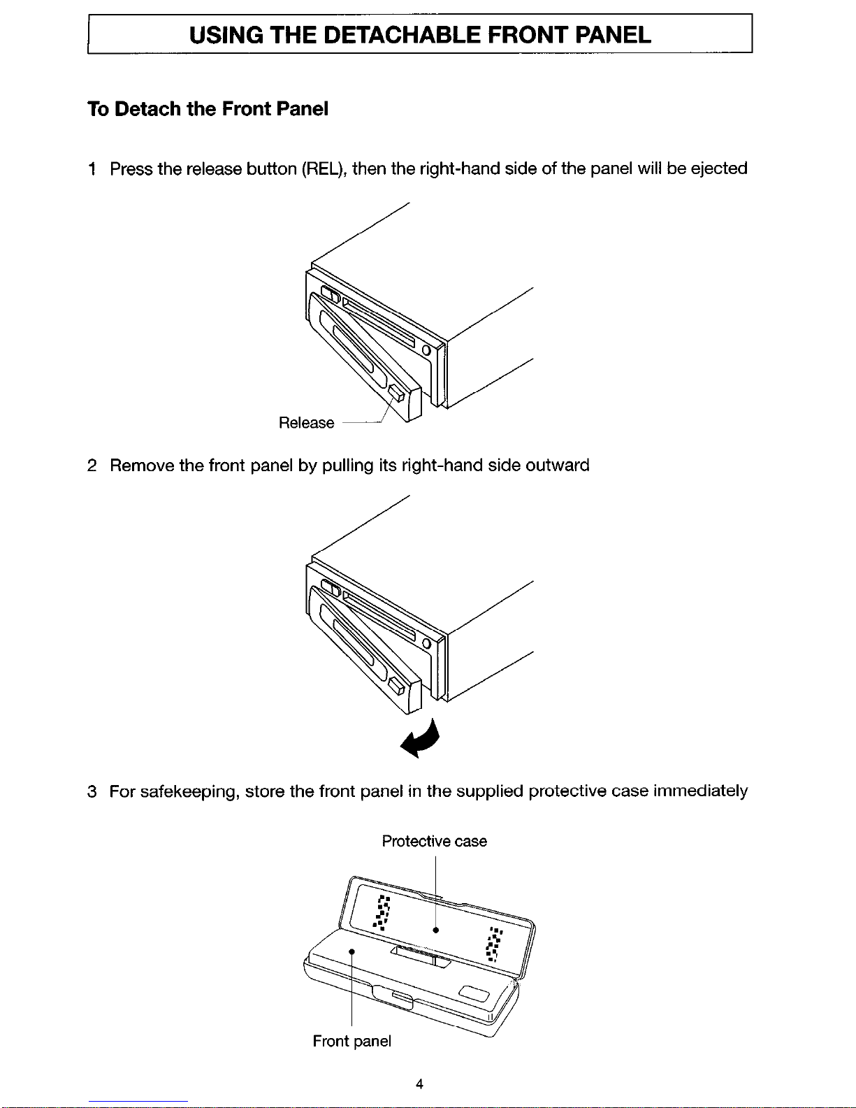
USING THE DETACHABLE FRONT PANEL
To Detach the Front Panel
1 Press the release button (REL), then the right-hand side of the panel will be ejected
2 Remove the front panel by pulling its right-hand side outward
/
3 For safekeeping, store the front panel in the supplied protective case immediately
Protective case
Page 7
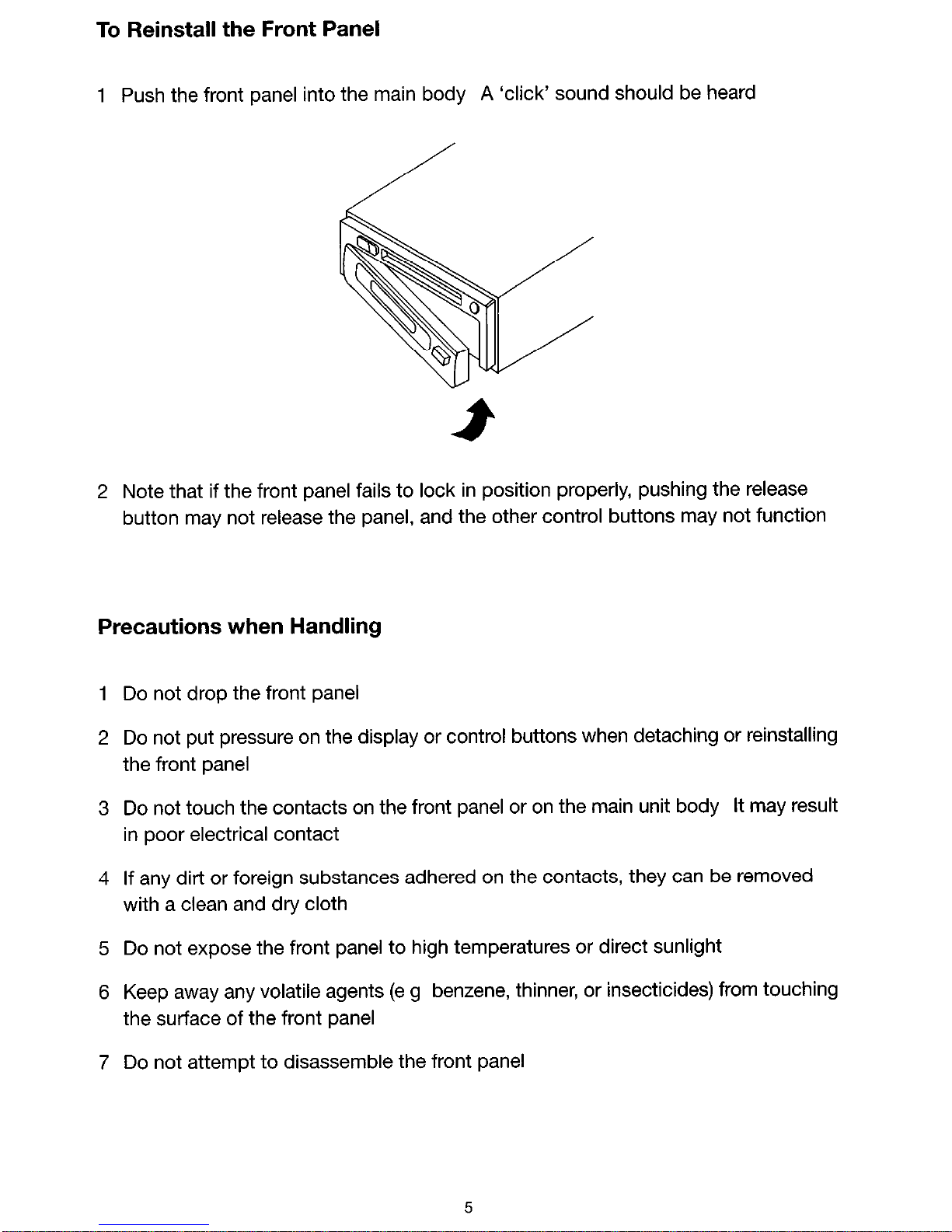
To Reinstall the Front Panel
1 Push the front panel into the main body A ‘click’ sound should be heard
2 Note that if the front panel fails to lock in position properly, pushing the release
button may not release the panel, and the other control buttons may not function
Precautions when Handling
1 Do not drop the front panel
2 Do not put pressure on the display or control buttons when detaching or reinstalling
the front panel
3 Do not touch the contacts on the front panel or on the main unit body It may result
in poor electrical contact
4 If any dirt or foreign substances adhered on the contacts, they can be removed
with a clean and dry cloth
5 Do not expose the front panel to high temperatures or direct sunlight
6 Keep away any volatile agents (e g benzene, thinner, or insecticides) from touching
the surface of the front panel
7 Do not attempt to disassemble the front panel
Page 8

I
ELECTRICAL CONNECTIONS
I
WIRING FOR ECD-HI340
I .II -----
4-speaker System _ _ _ _ , _ _ _ _ _ _ P-speaker System _ _ _ _ _
,
slack) emSpeaker I ;
(White/Black) 8 &=
- n Front Left i !
CB
g
n Front Riaht I I
(White)@&
,
=@I
Left I
--
Speaker ,
(Gray) CB 8
I
- - A Riaht ,
1 (Gray/Black) em Speake;
Ireen) $ @
Rear Left
Eew Speaker
Speaker j
00 not 1
Connect I
Do not I
Connect I
11111
--------------------__I
+12V Constant Power Supply (yellow)
fkignd
+12V Accessory/Switched (Red)
Wire (Black)
111 Power Antenna/Amplifier Turn On (Blue/Red)
Caution
l DO NOT connect any speaker wires to the metal body or chassis of the vehicle
l Connect each speaker wire directly to each speaker terminal
l All speaker common (-) wires must remain floating
1
Antenna socket
l Insert the plug from the antenna installed in your vehicle into this socket (if your
vehicle has a dual antenna system, a dual antenna to single antenna cable
adaptor may be required )
2
+12V Constant Power Supply (Yellow)
l Connect this wire to the +12V power terminal which receives power continuously
3 +12V Accessory/Switched (Red)
l Connect this wire to the terminal which receives power while the ignition switch
is ON or in the ACCESSORY position
l If the ignition switch does not have an ACC position, connect this wire to a +12V
power terminal which receives power continuously (Same as item 2 )
4 Ground wire (Black)
l Connect this wire to the vehicle chassis
5 Power Antenna/Amplifier Turn On (Blue/Red)
l Connect this wire to the control terminal of a Power Antenna or an external
amplifier
l When not using a Power Antenna or an external amplifier, this wire is not
connected
6
Page 9

Notes
- When using a two-speaker installation, the Green, Green/Black, Violet and
Violet/Black wires, which are used for a four-speaker installation, are not used
Cover the ends of these wires with electrical tape to prevent them from shorting to
the unit or the vehicle chassis
- When using a two speaker installation, set the FADER control to the center position
- When fuse replacement is necessary, remove the blown fuse by opening the Filter
Box , then install a new 1 amp fuse (switched power supply) or 15 amp fuse
(constant power
supply)
I
FILTER BOX
- RCA Line Out Jacks
Connect a patch cable (not supplied) from the White (left rear channel) and Red
(right rear channel) RCA line output jacks to the line input terminals of an external
amplifier
CAUTION -USE OF CONTROLS OR ADJUSTMENTS OR PERFORMANCE OF
PROCEDURES OTHER THAN THOSE SPECIFIED HEREIN MAY RESULT IN
HAZARDOUS RADIATION EXPOSURE
THE COMPACT DISC PLAYER SHOULD NOT BE ADJUSTED OR REPAIRED BY
ANYONE EXCEPT QUALIFIED SERVICE PERSONNEL
This compact Disc Player is made and tested to meet exacting safety standards It
meets FCC requirements and complies with safety performance standards of the U S
Department of Health and Human Services
THIS PRODUCT COMPLES WITH DHHS RULES 21 CFR
SUBCHAPTER J PART 1040 IO AT DATE OF MANUFACTURE
7
Page 10

LOCATION AND FUNCTION OF CONTROLS
1. ON/OFF
Press POWER button (1) to turn on
Press POWER again to turn it off If the
power is off, press BND button (12) or MOD button (13) also can turn on the unit
2. DISC PLAY
Gently insert a compact disc with the label side facing up into the disc slot (2)
The disc is then automatically loaded into the unit and starts playing with the first
track of the disc The digital display will indicate the track number
3. MUTE
Press the MUT button (3) to silence the receiver Press again to resume listening
8
Page 11
4. MONO/STEREO
Press MON button (4) to select monaural or stereo (Mono reception for radio
stations) You can sometimes improve reception of distant stations by selecting
mono operation
5. FACEPLATE RELEASE
Press REL button (5) to detach the removable faceplate
6. LOUDNESS
Press LOU button (6) to increase bass output and display will show “LOUD”
7. SET THE CLOCK
Press and hold the DSP button (7), then press the TUNE/SKIP + /b> button (16)
to change minutes or TUNE/SKIPd - button (15) to change hours
8. EJECT
Push a CD into slot The CD will begin to play Press P (eject) button (8) to stop
CD play and eject CD from slot Receiver switches to radio operation
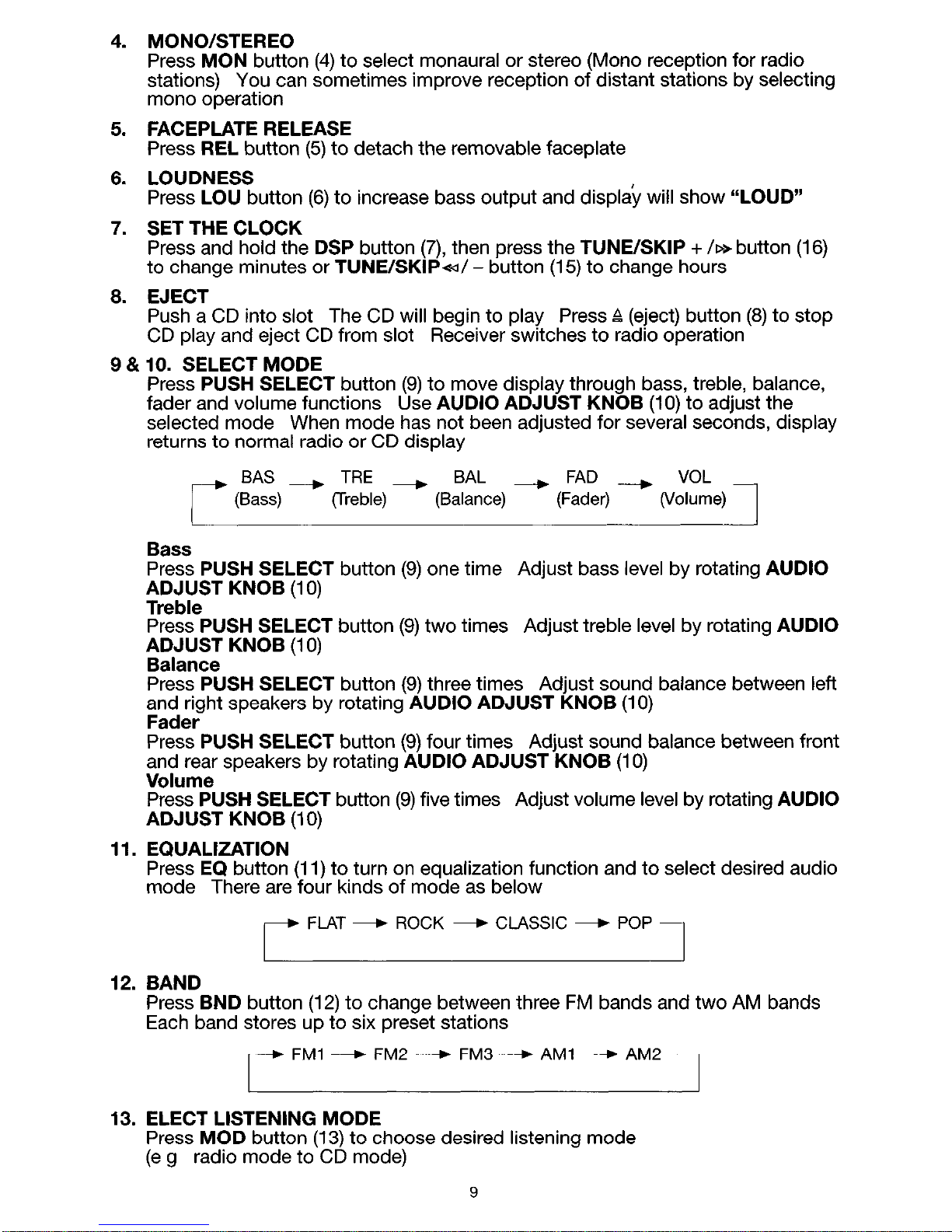
9 &IO. SELECT MODE
Press PUSH SELECT button (9) to move display through bass, treble, balance,
fader and volume functions Use AUDIO ADJUST KNOB (10) to adjust the
selected mode When mode has not been adjusted for several seconds, display
returns to normal radio or CD display
BAS --) TRE --) BAL --, FAD ----) VOL
(Bass) (Treble)
(Balance) (Fader) (Volume)
1
Bass
Press PUSH SELECT button (9) one time Adjust bass level by rotating AUDIO
fDD;ST KNOB (10)
Press PUSH SELECT button (9) two times Adjust treble level by rotating AUDIO
;,9Ja;lz; KNOB (10)
Press PUSH SELECT button (9) three times Adjust sound balance between left
;n,dd;rht speakers by rotating AUDIO ADJUST KNOB (10)
Press PUSH SELECT button (9) four times Adjust sound balance between front
and rear speakers by rotating AUDIO ADJUST KNOB (10)
Volume
Press PUSH SELECT button (9) five times Adjust volume level by rotating AUDIO
ADJUST KNOB (10)
11. EQUALIZATION
Press EQ button (11) to turn on equalization function and to select desired audio
mode There are four kinds of mode as below
r
FLAT - ROCK - CLASSIC - POP
1
12. BAND
Press BND button (12) to change between three FM bands and two AM bands
Each band stores up to six preset stations
r
FM1 ----) FM2 ---) FM3 4 AM1 --) AM2
1
I
I
13. ELECT LISTENING MODE
Press MOD button (13) to choose desired listening mode
(e g radio mode to CD mode)
9
Page 12

14. LIQUID CRYSTAL DISPLAY
The LCD (14) can show the current state of the unit
15 & 16. SELECT STATIONS
Press and release a TUNE/SKIPd - button (15) or TUNE/SKIP + /B button (16)
immediately to move radio frequency number down or up on step
Press and hold a TUNE/SKIPd - button (15) or TUNE/SKIP + /D> button (16)
for several seconds to seek the next clear station
15 & 16. SKIP TRACKS
Press a TUNE/SKIPd - button (15) or TUNE/SKIP + /W button (16) to move to
the previous track or the following track
Track number shows on the display
15 & 16. FAST FORWARD AND FAST REVERSE
17.
16.
19.
20.
21.
22.
23.
Press a TUNE/SKIP<=I/ - button (15) or TUNE/SKIP + /p.> button (16) to fast
reverse or fast forward CD play starts from when you release the button
PRESET STATIONS
Six number buttons (17) store and recall stations for each band
Store a station
Select a band (12) (if needed) Select a station Hold a preset button for several
seconds
Recall a station
Select a band (12) (if needed) Press a preset button to select stored station
TOP: PLAY THE FIRST TRACK
Press TOP button (18) to play the first track of the current disc
REPEAT THE SAME TRACK
Press RPT button (19) to continuously repeat the same track Press again to stop
repeat
INTRO: PREVIEW ALL TRACKS
Press SCN button (20) to play first several seconds of each track on the current
disc Press again to stop intro and listen to track
RANDOM: PLAY ALL TRACKS
Press RND button (21) to play all tracks on CD in random
Press again to cancel
the function
AUTOMATICALLY STORING & PROGRAM SCANNING
Automatically Storing
Press and hold AS/PS button (22) for several seconds to toggle automatically
storing function It starts searching next frequency and stores the clear station
into the preset memory At the end of automatically storing operation, mode is
changed to Preset Scan
Preset Scanning
Press ASIPS button (22) shortly to toggle preset scanning function During the
scanning, it will stop at every stored station for several seconds and the number
of the channel being scanned flashes on the display Press it again to stop
scanning
RESET BUTTON FUNCTION
RESET button (23) is placed on the housing and must be activated with either a
ball point pen or thin metal object The reset button is to be activated for the
following reasons
l Initial installation of the unit when all wiring is completed
l All the function buttons do not operate
l Error symbol on the display
Note: If RESET button (23) is pressed and the unit doesn’t work yet, please use
a cotton swab soaked in isopropyl alcohol to clean the socket on the back of the
front panel
10
Page 13

MODEL ECD-HI 340 SPECIFICATIONS
FM TUNER SECTION
Frequency Range . . ..__-...._----._------------------------ 87 5 MHz - 107 9 MHz
Usable Sensitivity . . . . _. . . . _ _ _ . . _. . __ _ __. . __ _. . . . . . . 17 23 dBf
50 dB Quieting Sensitivity . . . . . . . . . . . . . ..__. . . ..__ . ..__ 20 76 dBf
Frequency Response ---__------------.-------------------~------~~ 40 Hz - 12 KHz
I F Response Ratio .___-_..__----.___----~--------------------------------~~. 80dB
ImageResponseRatio -_----- ____ ---- __.. -- ___...___......__................ 50dB
Signal-to Noise Ratio -------------------______ ____ -- _______ ___....___...... 60 dB
Alternate Channel Selectivity ___.. - ___....____.... ._.... . . . . . . . . . . . 50 dB
Stereo&par&ion __----___-------------------------------~------~~~----~~~.- 30dB
CaptureRatio ___....__ -- . . .._ --- _.._ -----_--------------------------------~~ 15dB
Antenna Impedance ----__--------------------------------~------~~-----~~..~~ 75Q
AM TUNER SECTION
Frequency Range ------_------__.--- ___.. -- __.....___........ 530 KHz - 1710 KHz
UsableSensitivity(S/N20dB) ----------__----- ____ --- ____. ____....___....._ 2OpV
I F. Response Ratio -----__-------_------------------------~------~~~-----~~.. 60dB
Image Response Ratio --.._-----___------------------------------~~---~~~~.~ 36dB
Signal-to-NoiseRatio --_-------__---- __.._ -- _-__..___.....___..............- 50dB
Antenna Impedance -----------__----- __.. -- ___...____....._................... 75Cl
COMPACT DISC SECTION
DiscSize ----------------------------------------~.-----~~~-----~~~---~~~...~~~. 5”
Sampling Frequency --------------------_____________ ____._ - ____... -- __... 44 1 KHz
Digital Filter -----------__-------_____ ___.. --- ___...____....___.... 8xOversampling
Digital-to-Analog Converter -----_-------_-------~~--- ______ -- ____.. -__ Single, l-Bit
Pickup ____.....__......__................... Optical 3-Beam Semiconductor Laser
Output Filter ._--...__---_..~_----~~~------~--------------------------------- Active
AUDIO SECTION
Maximum Power Output --------------------------------~~------~~~----~~~ 40W x4
Load Impedance . ..___._..___...___.... .___..... . . . . . . . . . . . . .._.... 4Q
GENERAL
OperatingVoltage ..____....__ ---.__----- ____ -----__-------_---- 12V(144VTypical)
Operating Current Maximum _ _. . - -_ _ _. . . - _. . . _ _ _. . . . . ._ _. . . . _. . . . . . .15A
lnstallationsize(WxHxD) ---___----- ____ ---- __.. --- ___... -__ 200x785x142mm
IMPORTANT INFORMATION
Because its products are subject to continuous improvement, SANYO reserves
the right to modify product designs and specifications without notice and without
incurring any obligation
11
Page 14

I
TROUBLE SHOOTING
~~~ 1
Before going through the check list, check wiring connection
If any of the problems
persist after check list has been made, consult your nearest service dealer
Symptom Cause
No power The car ignition is not on
Solution
If the power supply is properly
connected to the car accessory
terminal, switch the ignition key to
“ACC”
The fuse is blown Replace the fuse
Disc cannot Presence of CD disc
Remove the disc in the player, then
be loaded or inside the player
put a new one
ejected
Inserting the disc in
Insert the compact disc with the
reverse direction label facing upward
Compact disc is extremely Clean the disc or try to play a new
dirty or defective disc one
Temperature inside the Cool off or until the ambient
car is too high temperature return to normal
Condensation
Leave the player off for an hour or
so, then try again
No sound Volume is in minimal
Wiring is not properly
connected
Adjust volume to a desired level
Check wiring connection
The operation The built-in microcomputer Press the RESET button
keys do not is not operating properly Front panel is not properly fixed into
work due to noise its place
Sound skips The installation angle is Adjust the installation angle to less
more than 30 degrees than 30 degrees
The disc is extremely dirty Clean the compact disc Then try to
or defective disc play a new one
The radio does The antenna cable is not Inset-t the antenna cable firmly
not work The connected
radio station
automatic
The signals are too weak Select a station manually
selection does
not work
12
Page 15
SANYO MOBILE AUDIO
MODEL ECD-H1340 LIMITED WARRANTY
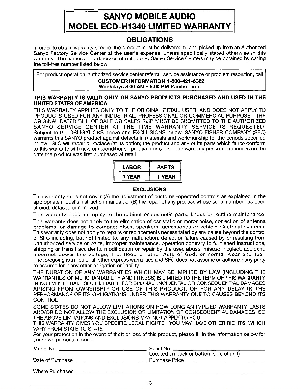
OBLIGATIONS
In order to obtain warranty service, the product must be delivered to and picked up from an Authorized
Sanyo Factory Service Center at the user’s expense, unless specifically stated otherwise in this
warranty The names and addresses of Authorized Sanyo Service Centers may be obtained by calling
the toll-free number listed below
For product operation, authorized service center referral, service assistance or problem resolution, call
CUSTOMER INFORMATION l-800-421-6382
Weekdays 8~00 AM - 500 PM Pacific Time
THIS WARRANTY IS VALID ONLY ON SANYO PRODUCTS PURCHASED AND USED IN THE
UNITED STATES OF AMERICA
THIS WARRANTY APPLIES ONLY TO THE ORIGINAL RETAIL USER, AND DOES NOT APPLY TO
PRODUCTS USED FOR ANY INDUSTRIAL, PROFESSIONAL OR COMMERCIAL PURPOSE THE
ORIGINAL DATED BILL OF SALE OR SALES SLIP MUST BE SUBMITTED TO THE AUTHORIZED
SANYO SERVICE CENTER AT THE TIME WARRANTY SERVICE IS REQUESTED
Subject to the OBLIGATIONS above and EXCLUSIONS below, SANYO FISHER COMPANY (SFC)
warrants this SANYO product against defects in materials and workmanship for the periods specified
below SFC will repair or replace (at its option) the product and any of its parts which fail to conform
to this warranty with new or reconditioned products or parts The warranty period commences on the
date the product was first purchased at retail
LABOR PARTS
1 YEAR 1 YEAR
EXCLUSIONS
This warranty does not cover (A) the adjustment of customer-operated controls as explained in the
appropriate model’s instruction manual, or(B) the repair of any product whose serial number has been
altered, defaced or removed
This warranty does not apply to the cabinet or cosmetic parts, knobs or routine maintenance
This warranty does not apply to the elimination of car static or motor noise, correction of antenna
problems, or damage to compact discs, speakers, accessories or vehicle electrical systems
This warranty does not apply to repairs or replacements necessitated by any cause beyond the control
of SFC including, but not limited to, any malfunction, defect or failure caused by or resulting from
unauthorized service or parts, improper maintenance, operation contrary to furnished instructions,
shipping or transit accidents, modification or repair by the user, abuse, misuse, neglect, accident,
incorrect power line voltage, fire, flood or other Acts of God, or normal wear and tear
The foregoing is in lieu of all other express warranties and SFC does not assume or authorize any party
to assume for it any other obligation or liability
THE DURATION OF ANY WARRANTIES WHICH MAY BE IMPLIED BY LAW (INCLUDING THE
WARRANTIES OF MERCHANTABILITY AND FITNESS) IS LIMITED TO THE TERM OF THIS WARRANTY
IN NO EVENT SHALL SFC BE LIABLE FOR SPECIAL, INCIDENTAL OR CONSEQUENTIAL DAMAGES
ARISING FROM OWNERSHIP OR USE OF THIS PRODUCT, OR FOR ANY DELAY IN THE
PERFORMANCE OF ITS OBLIGATIONS UNDER THIS WARRANTY DUE TO CAUSES BEYOND ITS
CONTROL
SOME STATES DO NOT ALLOW LIMITATIONS ON HOW LONG AN IMPLIED WARRANTY LASTS
AND/OR DO NOT ALLOW THE EXCLUSION OR LIMITATION OF CONSEQUENTIAL DAMAGES, SO
THE ABOVE LIMITATIONS AND EXCLUSIONS MAY NOT APPLY TO YOU
THIS WARRANTY GIVES YOU SPECIFIC LEGAL RIGHTS YOU MAY HAVE OTHER RIGHTS, WHICH
VARY FROM STATE TO STATE
For your protection in the event of theft or loss of this product, please fill in the information below for
your own personal records
Model No Serial No
Located on back or bottom side of unit)
Date of Purchase Purchase Price
Where Purchased
13
Page 16

21605 Plummer Street
Chatsworth, CA91 311
ECD-HI340 Issue Number 1
Printed in Hong Kong
88.CO602-03
 Loading...