

Page 1
.
.,
.,
INSTRUCTION
MANUAL
GCD 1500
si//’k
CD STEREO SOUND SYSTEM
.
.
.
.,
,
Page 2
i,
1
L
CAIJTION-INVISIBLELASER
F---
RADIATIONWHENPANEL
----
OPENANOINTERLOCK
OVERRIDDEN.
H
0
.
Td-
11
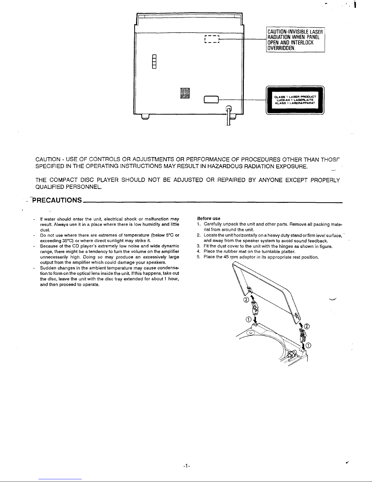
CAUTION - USE OF CONTROLS OR ADJUSTMENTS OR PERFORMANCE OF PROCEDURES OTHER THAN THOSf_
SPECIFIED IN THE OPERATING INSTRUCTIONS MAY RESULT IN HAZARDOUS RADIATION EXPOSURE.
—
THE COMPACT DISC PIAYER SHOULD NOT BE ADJUSTED OR REPAIRED BY ANYONE EXCEPT PROPERLY
QUALIFIED PERSONNEL.
-
‘-PRECAUTIONS
If water should enter the unit, electrical shock or malfunction may
Before use
result. Always use it in a place where there is low humidity and little
1.
dust.
Do not use where there are extreme$ of temperature (below 5°C or
2.
exceeding 35”C) or where direct sunlight may strike it.
- Because of the CD player’s extremely low noise and wide dynamic
3.
range, there might be a tendency to turn the volume on the amplifier
4.
unnecessarily high. Doing so may produce an excessively large
5.
output from the amplifier which could damage your speakers.
- Sudden changes in the ambient temperature may cause condensation to form on the optical lens inside the unit. if this happens, take out
the disc, leave the unit with the disc tray extended for about 1 hour,
and then proceed to operate.
Carefully unpack the unit and other parts. Remove all packing material from around the unit.
Locate the unit horizontally on a heavy duty stand or firm level surface, “
and away from the speaker system to avoid sound feedback.
Fit the dust cover to the unit with the hinges as shown in figure.
Place the rubber mat on the turntable platter.
Place the 45 rpm adaptor in its appropriate rest position.
-1-
Page 3

1
COiiNECTIONS
.
L
..
FM outdoor aerial
%
Simple indoor aerial
II
3-
Power supply
Connect the mains lead to an AC 230-240 V wall outlet.
Note:
AM loop aerial
P
Q
r
- Do not connect the mains lead to an AC outlet until all connections
have been made.
- Before connecting the mains lead, set the POWER switch to OFF.
II ,
Aerials
In areas close to a transmitter the simple indoor aerial is sufficient to
receive broadcasts. Extend the aerial wire as straight as possible and,
while listening to the sound from the system, secure it in a position which
yields minimal distortion and noise,
In fringe areas or where reception is distorted or noisy, an external aerial
(not supplied) should be connected instead of the simple indoor aerial.
Consult your dealer.
loop
aerial
~ssemble the loop aerial as shown in figure.
Unwind the aarial wires (about 3 turns), then connect them to the AM
LOOP ANT. terminals. Place the loop aerial in a position which yields the
best AM reception, or attach it to a wall or other surface as shown in figure.
(not supplied)
Note:
- To minimize noise, the speaker, mains and any other leads should not
come close to the ~. ANT. socket.
- Do not place the unit beside a metal surface.
Speaker terminals (SPEAKERS)
These terminals will accept speakers of 8 ohms minimum impedance.
The speaker wires should be connected to the speaker terminals with the
proper polarity. The red terminals are (+) positive and black terminals are
(-) negative.
Headphones socket (PHONES)
Connect stereo headphones (8 ohms - 10 kohms, not supplied) for
monitoring orfor private listening. The speakers are automatically disconnected when headphones are connected to this socket.
-2-
Page 4
.
‘d
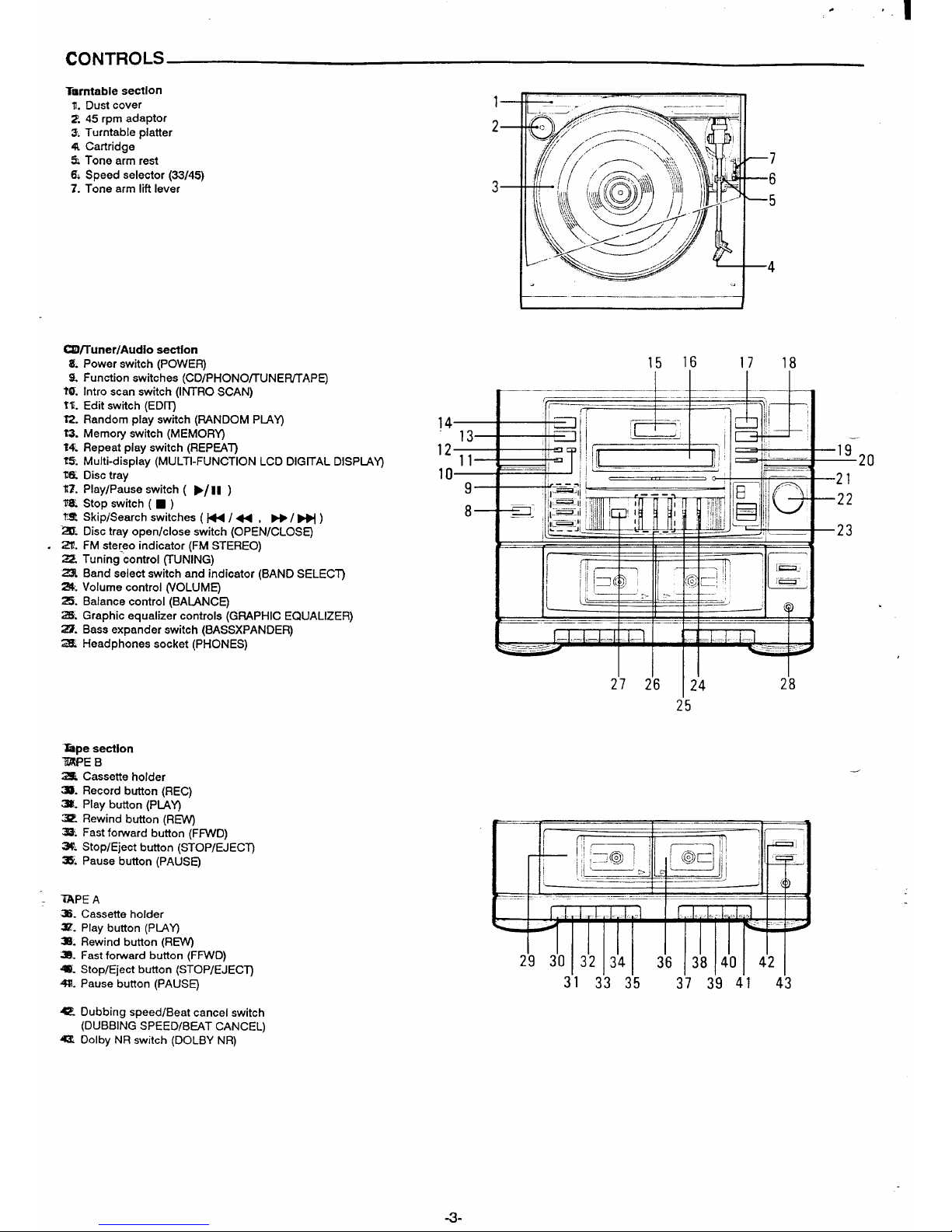
CONTROLS
Trsrntable section
1.
Dust cover
2.45 rpm adaptor
3. Turntable platter
4t Cartridge
% Tone armrest
6, Speed selector (33/45)
7. Tone arm Mt lever
W/Tuner/Audio section
Power switch (POWER)
Function switches (CD/PHONOfRJNE~APE)
Intro scan switch (INTRO SCAN)
Edit switch (EDLr_)
Random play switch (RANDOM PIAY)
Memory switch (MEMOR~
Repeat play switch (REPEAT)
Multi-display (MULTI-FUNCTION LCD DIGITAL DISPLAY)
Disc tray
Play/Pause switch (
➤1 II )
Stop switch ( 9 )
Skip/Search switches ( W /44 , ~/~)
Disc tray open/close switch (OPEN/CLOSE)
FM stereo indicator (FM STEREO)
22. Tuning-control (TUNiNG) ‘
23 Band select switch and indicator (BAND SELECT)
24. Volume control (VOLUME)
25. Balance control (BAIANCE)
2S. Graphic equalizer controls (GRAPHIC EQUALIZER)
22. Bass expander switch (BASSXPANDER)
2S Headphones socket (PHONES)
Zspe section
WEB
Z?5i Cassette holder
=. Record button (REC)
=. Play button (PIA~
3? Rewind button (RW
=. Fast forward button (FFWD)
3$. Stop/Eject button (STOP/EJECT)
=. Pause button (PAUSE)
~PE A
=. Cassette holder
3Z- Play button (PIAY)
3Z Rewind button (REW)
33. Fast forward button (FFWD)
~. Stop/Eject button (STOP/EJECT)
4. Pause button (PAUSE)
15 16
——— 1..1 –..1 –L
1 r——-----=+ “--k=-
—
,.—...——.._. _ ._..
__—_
b--l--l
I u—
9
8
I 1!EET3il= IELI
2’7 2’6 I 24 2’8
25
3’1 3’3 3’5
3’7 3’!3 4’1 43
= Dubbing speed/Beat cancel switch
(DUBBING SPEED/BEAT CANCEL)
= Dolby NR switch (DOLBY NR)
-3-
Page 5

“
BEFORE OPERATION
P:ess the POWER switch.
Bass expander switch (BASSXPANDER)
To turn off the power, press it again.
Press the switch to the ON position to enhance the bass sound.
Adjusting the volume
WHAT TO DO IF ...
Move the VOLUME control upwards to increase volume or downwards to
If the operation of the unit or display is not normal, turn off the POWER
decrease volume.
switch. Then turn it on again and resume the operation.
Adjusting the Ief’flrighl speakef
balance
Use the BALANCE control to adjust the lefVright speaker balance.
Adjusting the sound quality
The GRAPHIC EQUALIZER controls (300HZ1 kHz/1 OkHz) allow the
sound to be tailored to individual musical preferences or to fit the acoustics of the room. Moving the control will adjust the sound level in
a narrow
range of musical frequencies.
CD PLAY
Use compact discs hearing the symbol shown below. In addition to
conventional 12 cm CDs, this system can be used to play 8 cm CDs
without an adapter.
L
misi!
DIGITALAUDIO
1. Press the CD function switch.
“no diSC” appears on the display.
2. Press the OPEN/CLOSE switch.
The disc tray slides out.
The display shows “OPEn”.
3. Place the disc with the label facing up on the disc tray.
E
al o
0
0
.
For 12 cm CD
For 8 cm CD
4. Press the OPEN/CLOSE switch again to close the disc tray.
The total number of tracks and total play time on the disc appear.
,VOTE:
5.
6.
If a disc is loaded upside down, or if no disc is loaded, “no diSC” will
appear on the display.
Press the “
➤/11
“ switch.
“PL4Y F “ appears on the display and play starts from the first track.
The following information are displayed:
- The current track number.
- Elapsed time for the current track.
NOTES:
- If the”
➤/ii
“ switch is pressed after the disc has been placed in
the disc tray, the disc tray will close and play will start.
Ifyou wish to start play from a desired track, press the” ~ / ~ “
switch until the desired track number is shown on the display .Then
press the “
➤/II “ switch.
Press the “
■ “ switch to end disc play.
When the last track has been played, the player automatically stops.
The total number of tracks and total play time are displayed.
When the OPEN/CLOSE switch is pressed during play, play will stop
and the disc tray will slide out.
Notes on handlina com~act discs
Do not expose-the disc to direct sunlight, high humidity or high
temperatures for extended periods of time.
Discs should be returned to their cases after use.
Do not apply paper or write anything on the disc surface.
Handle the disc by its edge. Do not touch the playing surface (glossy
side).
Fingerprints and dust should be carefully wiped off the playing
surface of the disc with a soft cloth.
Wipe in a straight motion from the centre to the outside of the disc.
Never use chemicals such as record cleaning sprays, antistatic sprays
or fluids, benzine or thinner to clean compa-ct ‘discs.
Temporarily stopping
play
Press the”
➤/II “switch. “PIAY F “ blinks. To resume play, press the
switch again.
Skip play
To skip to track 6 while track 3 is playing, press the ~ / M switch
repeatedly until “6” appears on the display.
To skip back to track 3 while track 6 is playing, press the~ /44 switch
repeatedly until “3” appears.
Search (forward/reverse)
If the w / ~ or ~/ 44 switch is pressed during play, the player will
search at high speed in the forward or reverse direction while the switch
is being pressed. When the switch is released, normal play will continue.
- While the “ ~ / ~ “ or “ ~ / ~ “ switch is pressed, the sound
will be reduced in volume.
Introscan
Press the INTRO SCAN switch to play the first 10 seconds of each track.
“INTRO” appears on the display.
- Press the INTRO SCAN switch again to return to normal play.
- Ifthe INTRO SCAN switch is pressed during normal play, introscan will
start with the next track on the disc.
- press the “ ~ / ~ “ or” W / ~ “ switch to skip to another track
during introscan play.
Random
play
Press the RANDOM PIAY switch to begin random play. The player will
automatically select and play tracks on the disc at random. “RANDOM”
appears on the display.
If the RANDOM PMYswitch is pressed during random play, the player
will select the next random track.
Random Introscan play
Press the INTRO SCAN switch, then the RANDOM PIAY switch, to play
the first 10 seconds of each track at random.
Repeat
play
Before or during play, press the REPEAT switch. The player will play all
the tracks, all the programmed tracks or all the random play tracks
repeatedly. ‘$~” appears on the display.
To cancel repeat play, press the REPEAT switch again. “~” goes out.
-4-
Page 6

PROGRAMMED PLAY
(.@
to 24 selections on a disc can be programmed for play in any order.
To begin the Pro9rammin9 procedure, select the CD function first.
The same track can be Programmed more than once.
&le:
To programme tracks 5, 2, 6 and 10
1.
2
3
4.
5.
6.
..
Pre& the MEMORY switch. “PROG.” blinks on the display.
PROG.
/l\
1 Pr. 1
Select track 5 by pressing the” F+ / ~” switch.
PROG.
/l\
5 Pr. 1
Press the MEMORY switch. “PROG.” remains lit.
PROG.
5 Pr. 1
Select track 2 by pressing the M / 44 switch. “PROG.” blinks on
the diplsy.
PROG.
/l\ 2pr.2
Press the MEMORY switch. “PROG.” remains lit.
PROG.
2 Pr. 2
The remaining tracks can be programmed in the same way,
Press the
➤/10 switch to start play.
When all programmed selections have played, the player stops
automatically.
- The programme contents are retained in memory.
The maximum number of selections that can be programmed is 24. If
you try to enter more selections,
“FULL” will appear on the display.
..
LISTEI!JING TO TAPES
TAPE A is for playback only; TAPE B is for both playback and recording.
Uo not turn the unit off while the tape is running. Otherwise, the pinch
roller may be damaged.
Pfayback (TAPE A or TAPE B)
Press the STOP/EJECT bu~on to open the cassette holder.
Load the cassette(s).
To load, place the tape with its exposed end at the bottom. After the
tape has been loaded, push the cassette holder back into position.
Press the TAPE function switch.
Set the DOLBY NR switch to ON or OFF according to whether the tape
has been recorded with the Dolby NR system or not.
Press the PIAY button.
Press the STOP/EJECT button to stop playback at any time.
When the end of the tape has been reached, automatic stop will be
activated.
Types of
usable tapes
The following types of tape can be used with the both decks.
Normal
Cr02
Notes:
Cr02 tapes without sensing holes cannot be used since they cannot
be identified by the auto tape selector.
- Endless tapes cannot be used.
Do not use C-120 tapes. They may jam in the mechanism.
Pause
Press the PAUSE button to temporarily stop playback or recording. Press
the button again to re-start playback or recording.
The programme is cleared in the following cases:
When the “
■ “ switch is pressed in the stop mode
When the EDIT switch is pressed in the stop mode
- When the OPEN/CLOSE switch is pressed
- When other source is selected
When the power is switched off
Checking the
programme
Whenever the MEMORY switch is pressed in the stop mode, the programmed track numbers sequentially appear on the display.
To
add a new selection to a programme
1. In the stop mode, press the MEMORY switch repeatedly until the
following display appears:
“----- -“
2. Select a track number.
3. Press the MEMORY switch.
To
change a selection
1. Press the MEMORY switch repeatedly until the selection to be re-
placed is displayed.
2. Select a track number.
3. Press the MEMORY switch.
Operations during programmed
play
press the ~ / ~ or ~ / + switch to skip programmed tracks.
If the end (or beginning) of the current track is reached in forwar
reverse) search mode, the player enters the pause mode. —
Fast forward and rewind
Press the FFWD or REW button.
When the tape has been wound to the end (or beginning), the fast forward .
or rewind function will be autom~”cally released.
Note:
While playing or recording, do not press the FFWD or REW button of the
other tape mechanism, as it may result in inferior sound quality.
Continuous Diavback (From TAPE A to TAPE B)
1.
2.
3.
Press the b~Y butt~n of TAPE A. TAPE A will begin to play back,
Press the PAUSE button of TAPE B.
Press the PLAY button of TAPE B (TAPE B will not move).
When the tape automatically stops”on TAPE A, TAPE B automatically
starts playback.
When the end of the tape has been reached on TAPE B, autorrtic
stop will be activated.
Dolby NR system
Dolby Noise Reduction circuitry provides superior recording and playback results by suppressing tape hiss by up to 10 dB for virtually noise
free recordings.
Dolby noise reduction manufactured under license from Dolby Laboratories Licensing Corporation.
“DOLBY” and the doubIe-D symbol
Laboratories Licensing Corporation.
DO are trademarks of Dolby
-5-
Page 7

.
.“,
LISTENING TO THE RADIO
i
1. Press the TUNER function switch.
BAND SELECT
Switch
2.
Select the desired band (and FM mode) using the BAND SELECT
FM MONO:
switch.
For receiving weak (noisy) FM stereo broadcasts. The reception may
3. Tune in a desired station by turning the TUNING control.
be inproved, but the sound will be monaural.
FM STEREO:
For receiving FM stereo broadcasts. The FM STEREO indicator will
light when an FM stereo broadcast is received.
AM:
For receiving AM broadcasts.
LISTENING TO RECORDS
Note:
1.
- Remove the stylus protector.
2.
- Be sure that the tone arm is detached from the tone arm rest before
3.
operation, and re-secured again after use.
- Do not turn the turntable platter counter-clockwise.
4.
- When operating the unit for the first time, the tone arm might return to
its rest position. This is not a malfunction.
5.
- When operating the unitforthefirst time, the tone arm might not return
to its rest position. Should this occur, shift the arm lift lever to up and
6.
,,ently move the tone arm to near the centre shaft of the turntable. The
‘tone arm will automatically return to its rest position, This is not a
malfunction.
- Never grasp or hold the tone arm and platter during operation of the
7.
automatic mechanism.
.
BEFORE RECORDING AND DUBBING
Press the PHONO function switch.
Place a record on the platter (if required, use the 45 rpm adaptor).
Select the speed with the speed selector depending on the disc to be
played (33 or 45 rpm).
Shift the arm lift lever backward.
The tone arm will ascends from the tone arm rest.
Slowly move the tone arm to the desired position by hand. The platter
will begin to rotate.
Shift the arm lift lever forward. The tone arm will then descend onto the
disc,
- If you wish to momentarily stop disc play, shift the arm lift lever
backward. Shift it forward to start disc play again,
When play is finished, the tone arm will return to its rest position and
the platter will cease rotation automatically.
‘~
Recording copyright material without permission of the copyright
owners is usually an infringement. If you wish to re-record copyright material permission from the copyright owner is necessary
SANYO does not approve of, and cannot be held responsible for,
any unlawful use of this machine.
This unit features ALC (Automatic Level Control) which automatically
adjusts the recording level.
Use TAPE B for recording.
* ‘ress the STOP/EJECT button and load the cassette for recording.
ewind the tape to the beginning.
3>Set the DOLBY NR switch to ON or OFF as desired.
During dubbing operation, the DOLBY NR switch has no effect to the
copied tape.
Accidental erasure prevention
tabs
(for protecting valuable recordings)
Accidental erasure can be prevented by breaking out the tabs on the end
of the cassette tape (where the tape is not exposed) using
a screwdriver
or similar implement.
If a tab is broken out in error and you wish to re-record the tape, simply
block the tab hole using adhesive tape and the tape can be used for
recording again.
A
r “deA ‘orcr02tape
I
J
Break out tab A for side A.
Break out tab B for side B.
-6-
Page 8

.
RECORDING COMPACT DISCS
EDIT RECORDING
NOTES:
The following edit recording operations can be performed.
- CD play starts automatically after 8 seconds, so the recorcjin~ will not
a) Time edit recording
be interrupted by the leader tape at the beginnin9 of sides A and B.
b) Programme edit recording
A short blank space is automatically recorded at the end of each track.
c) Backward skip edit recording
The highest track number which can be edited is 24.
a)
Time edit recording
Select track No. 4 or a subsequent which will fit in here if track No. 3 is too
long.
Unrecorded blank
I
SIDE A 25 min.
~r---
1
2
II
4+
1
‘1>
Manual reverse
6
3
SIDE B 25 min.
Track No. 4 is not recorded on this side.
The tracks on a CD are recorded in order within the assigned tape length.
4.
Any track that does not fit within the remaining time at the end of the tape
5.
is replaced automatically with a subsequent track that will fit within the
6.
available time.
To record all tracks on a6-track disc (total play time of 47 min 20 see), onto
a 50-minute tape:
1.
2.
3.
b)
Press the CD function switch.
Load the disc into the CD player.
Press the EDIT switch to select the recording tape length.
The display indicates:
EDIT SIDE-A
C-46
7.
Each time the EDIT switch is pressed, the tape length display changes
8.
in the following sequence:
~c-’6;:::;+c-60-c-74-::o~
To set the desired tape length up to C-99, use the “ ~ / + “ or “ M / ~ “ switch.
To set “C-50”, press the EDIT switch to select “C-46” and press the
“ ~ / ~ “ switch 4 times. “C-50” appears on the display.
Insert a C-5O cassette tape into the TAPE Btape deck to record side A.
Press the REC button to set the record pause mode for side A.
Press the”
➤/11 “ switch to start playback with track 1.
The deck starts recording.
—
PLAY p
EDIT SIDE-A
PROG.
1 0.01
When all of the tracks for side A have finished playing, the player will
go to pause mode at the beginning of the first track (Track 3) to be
recorded onto side B.
After the tape deck stops automatically at the end of side A, turn over
the cassette and reinsert it.
Press the REC button to start recording of side B.
The player will start playback with track 3.
When all tracks for side B have finished, disc play stops. The tape deck
will continue recording to the end of the tape (side B).
The edit mode remains operational when recording ends.
Press the “ g “ switch to cancel the edit mode.
Programme edit recording
Unrecorded blank
!A 23 min.
5
I
2
3
I
H I
‘[)
Manual reverse
h 7
4
1
I
Unrecorded blank
The desired selections can be rearrancred and
within a designated tape length. -
Example: ‘
The following tracks are to be recorded.
Track 5:10 min 00 sec
Track 2:7 min 26 sec
Track 3:4 min 37 sec
Track 1 :11 min 09 sec
Track 4:9 min 21 sec
Track 7:1 min 10 sec
recorded on the tape
1.
2.
3.
4.
5.
These tracks are recorded in the following order on a 46-minute tape.
SIDE A:
Track 5
Track 2
Track 3
SIDE B:
Track 1
Track 4
Track 7
SIDE B 23 min.
Press the CD function switch.
Load the disc into the CD Player.
Press the EDIT switch until “C-46” appears.
Press the MEMORY switch.
“PROG,” blinks and the display indicates:
\l/
EDIT SIDE-A
PROG.
/l\ 1 Pr. 1
Press the “ ~ / 44 “ or “ ~ / ~ “ switch to select the track
(Track 5).
\l/
EDIT SIDE-A
PROG.
/l\
5 Pr. 1
-7-
Page 9

-.
.
.
6.
7.
8.
c)
,.
.
i%ss the MEMORY switch.
“pROG.” remains lit.
EDIT SIDE-A
PROG.
5 13.00
The remaining time on side A eppears on the time display.
Repeat steps 5-6 to programme the tracks to be recorded onto side
A.
If a track which exceeds the remaining time on side A is selected,
“SIDE-A” blinks on the display.
When the MEMORY switch is pressed, “SIDE-A” disappears and
“SIDE-B” appears. The remaining time on side B appears on the
display. This and subsequent tracks are recorded on side B.
Repeat steps 5-6 to programme the tracks to be recorded onto side
B.
If a track exceeding the remaining time on side B is programmed,
“Err” will appear on the display for 4 seconds.
Backward skip edit recording
Track 4 will be interrupted.
ii
9. Insert the C-46 cassete tape into the tape deck to record side A.
10. Press the REC button on TAPE B.
11. Press the “
F/11 “ switch. Recording starts.
The programmed tracks will play in sequence starting from track 5,
and pause at the beginning of track 1.
\lJ\l/
PIAY
➤ EDIT
PROG.
SIDE-B
1 0.00
12. After the tape deck stops automatically at the end of side A, turn over
the cassette and reinsert it.
13. Press the REC button to start recording of side B.
The player will start playback with track 1.
When all tracks for side B have finished, disc play stops. The tape
deck will continue recording to the end of the tape (side B).
SIDE A
i
1
I
2
3 4
1>
Manual reverse
6
5
4
SIDE B
I
Track 8 will be interrupted.
This type of recording is the easiest to perform and the tape length setting
is not required.
1.
2
3.
4.
5.
Press the CD function switch.
Load a disc into the CD player.
Press the EDIT switch until “c---” appears on the display.
Press the REC button.
Press the “
➤/II “ switch. Recording starts on side A.
Record from the beginning of a track.
6. After the tape deck stops automatically at the end of side A, turn over
the cassette and reinsert it.
7. Press the REC button to stari recording of side B.
The player will start playback with the beginning of track 4.
When all tracks for side B have finished, disc play stops. The tape deck
will continue recording to the end of the tape (side B).
MANUAL RECORDING
For programmed recording, programme the material in advance (as
described under “PROGRAMMED PLAY”).
1. Press the CD function switch.
~ad a disc into the CD player.
~>,~ress the REC button,
4. Press the “
➤/11 “ switch. Recording starts.
TAPE DUBBING (TAPE A to TAPE B)
1.
2.
3.
4.
5.
6.
7.
Load the playback tape into TAPE A and a blank tape into TAPE B.
Automatic stop during dubbing
Press the’TAPE function switch.
a)
Wind the tape on TAPE A to the beginning of the tape or a particular
selection.
Select the dubbing speed with the DUBBING SPEED/BEAT CANCEL
b)
switch.
HIGH:
For dubbing the whole tape at high speed (twice normal speed). -
NORMAL:
For dubbing with monitoring at normal speed.
Press the PAUSE button of TAPE B, then press the REC button of TAPE B.
Press the PLAY button of TAPE A to start dubbing.
To stop the dubbing operation, press both STOP/EJECT buttons
simultaneously.
When TAPE A tape is longer than TAPE B:
When TAPE B stops automatically, TAPE A continues playback mode
at normal speed.
When TAPE B tape is longer than TAPE A:
When TAPE A stops automatically, TAPE B erases the tape to the end.
To dub other selections repeat steps 3-7 as described above.
If you change the function position during the dubbing operation,
TAPE B will continue to record the new sound source at normal speed.
Do not change the dubbing speed during the dubbing operation.
-8-
Page 10

-
.,.. .
----.— . . —.. .
,“
.
..’.., ---—
RECORDING FROM THE TUNER OR
.-
PHONO
1.
2.
3.
Tune in the radio station to be recorded, or play a record.
When beat interference is heard
press the REC button to start recording.
A high-pitched noise called “beat” is sometimes heard during the record.
press the
s_fop/EJEcT button to stop recording at any time.
ing of radio broadcasts.
When the end of the tape has baen reached, automatic stop will be
In cases like this, set the DUBBING SPEED/BEAT
CANCEL switch to the
activated.
position which will reduce the level of tha beat noise.
MAINTENANCE
.
Cleaning the stylus
From
time to time, the stylus must be checked for dust particles etc.
Cleaning is best carried out with a small very soft brush.
Stylus replacement
After along period of use or when an inferior sound is obtained, the stylus
assambly should be replaced with a new one. To remove the stylus
assembly, pull it downwards gently. To mount the new one, re-assemble
in reverse order.
Please see the label on the turntabla panel to find the stylus number.
Cleaning TAPE A and B heads
To ensure playback and recording with good-quality sound, use cotton
swab (1) to clean the heads (4,5, 8), pinch rollers (3, 7) and capstans (2,
6) of the decks after about every 10 hours of use.
If the dirt persists, soak the swab in a little methylated spirit or head
cleaning fluid and then clean.
W3
47--
4 8
Main unit
Use a soft cloth to remove dirt on the main unit.
If the dirt persists, dip a soft cloth into a diluted solution of nautral
detergent, wring it out, wipe away the dirt, and then take up any moisture
with a dry cloth.
Do not use benzine, thinners or alcohol since they will mar the finish of the
surfaces.
.
-9-
Page 11

SPECIFICATIONS
.
.
Turntable section
Drive system:
Belt drive
e
Tuner section
Frequency ran9e:
FM: 87.5-108 MHz
AM: 530-1700 kHz
Cassette deck section
Recording system:
AC bias, 4-track stereo
Rewind and fast forward time:
Approx. 120 sec. (C-60)
CD player section
Channels
2 channels
Frequency response
20-20,000 Hz
S/N ratio
94 dB
Channel separation
90 dB (1 kHz)
Distortion
).04% (1 kHz)
h%w and flutter
Undetectable
General
Output power:
5W x 2 (at 8 ohms, 10% distortion)
outputs:
SPEAKERS: 8 ohms
PHONES: 8 ohms
Power requirements:
AC: 230-240 V, 50 HZ
Power consumption:
28 W
Dimensions (W x D x H):
Approx. 360x 365x 355 mm
Specifications subject to change without notice.
,.
.
.
,
“.
.
i-
b
-1o-
Page 12

,-
“i
.
(AU) 1AD6P1OA23IO7
SANYO Electric Co., L[d
Printed in Singapore
 Loading...