

Page 1
FILE NO.
SERVICE MANUAL
REL
VOL
TUN
TRK
CD
PWR
Specifications
FM TUNER
Tuning Range.............................................................................. 87.5 - 107.9 MHz. (200 KHz. step)
Sensitivity .................................................................................... 2 µV (FXR-725GD)
Separation................................................................................... 30 dB (FXR-725GD)
Signal-to-Noise Ratio .................................................................. 65 dB (stereo), 70 dB (mono)
Full Panel Detachable
Auto Reverse Cassette
Player With CD Changer
Controller
CD CHANGER CONTROL
-
HI-POWER 40W x 4 FXC-755RDS
AUD
DISC
FXC-755RDS
87.5 - 108.0 MHz. (50 KHz. step)
1.2 µV (others)
35 dB (others)
FXR-725GD (A.SS)
114782847
FXR-725GD (SS)
114782846
FXR-725GD (XE)
114782839
FXR-730GD (A.SS)
114782842
FXC-750GD (A.SS)
114782843
FXC-755RDS (XE)
114782840
BAND/ATP
TA/AF
+
SCANRM/
RPTSHF
PTY
REG
AM TUNER
Tuning Range.............................................................................. 530 - 1,710 KHz. (10 KHz. step)
531 - 1,602 KHz. (9 KHz. step)
Sensitivity .................................................................................... 30 µV (FXR-725GD)
35 µV (others)
Signal-to-Noise Ratio .................................................................. 47 dB (FXR-725GD)
50 dB (others)
CASSETTE PLAYER
Tape Frequency Response ......................................................... 30 - 15,000 Hz.
Tape S/N Ratio ............................................................................ 45 dB
Wow & Flutter.............................................................................. 1.25 % WRMS
AUDIO AMPLIFIER & GENERAL
Maximum Output Power ............................................................. 35 W x 4 channels
40 W x 4 channels
Output Wiring .............................................................................. Floating-Ground type designed for 4-
speaker use
RCA low-level outputs: 2 channels
Output Impedance ...................................................................... 4 - 8 ohms
Power Supply .............................................................................. 12 volts DC, negative ground
Specifications are subject to change without notice.
REFERENCE No. SM-7900005
Page 2

CONTENTS
SERVICE NOTES and PRECAUTIONS............................................................................1
ELECTRICAL ADJUSTMENTS.....................................................................................2-10
BLOCK DIAGRAM ........................................................................................................... 11
IC/TRANSISTOR LEAD IDENTIFICATION......................................................................13
CASSETTE DECK MECHANISM EXPLODED VIEW .....................................................14
CABINET & CHASSIS EXPLODED VIEW..................................................................15-16
PARTS LIST - CABINET, CHASSIS AND ACCESSORIES.........................................17-18
PARTS LIST - CASSETTE DECK MECHANISM.............................................................19
PARTS LIST-MAIN ......................................................................................................21-32
PARTS LIST-DISP ......................................................................................................33-36
PARTS LIST-RF33 ......................................................................................................37-42
CIRCUIT BOARD DIAGRAM ............................................................... SEPARATE SHEET
SCHEMATIC DIAGRAM ...................................................................... SEPARATE SHEET
Page 3

SERVICE NOTES AND PRECAUTIONS
SERVICE NOTES
1. Make sure that the power lead is connected properly to
power source, otherwise damage to radio may result. If a
battery eliminator is used as a power source in place of a
battery, it must be filtered and regulated. (The power supply capacity should be more than 5 amps.)
2. Integrated circuits (ICs) are used in this unit. Because the
ICs are direc-coupled devices, as to all electronic equipment, reading within 10% of the indicated values are acceptable. Allowance must also be made for variations in
supply voltage. It is expected that any breakdown within
the IC results in drastic changes of the operating voltages
at the terminals.
3. When replacing a power output IC, remember to use the
IC specified in the parts list; Coat the IC-fin with sillicon
grease.
WARNING
ln using meters, signal generator and any tool in servicing
Ics, extreme care is needed. DO NOT SHORT THE IC TERMINALS TO THE PATTERN ON THE PC BOARD OR TO
EACH OTHER. THE IC WILL BE INSTANTANEOUSLY DESTROYED.
ALIGNMENT PROCEDURE
Alignment is performed at factory with laboratory equipment.
Therefore, before alignment is attempted, the unit should be
thoroughly checked for circuit troubles.
NOTES:
1. Check for specified source voltage-DC, 14.4volts.
2. Connect an AC voltmeter (AC VM) across speaker or
dummy load (4 ohms. 20W , wirewound resistor)...see Fig.
1-3. (ELECTRICAL ADJUSTMENTS)
3. Signal input must be kept as low as possible to avoid overload and clipping (use highest sensitivity of output indicator).
4. Repeat adjustment to ensure good results.
5. Non-metallic alignment tools must be used (especially at
FM alignment).
6. For alignment location details, refer to CIRCUIT BOARD
PARTS LOCATION.
INSTALLATION PROCEDURE
1. To prevent a short circuit, remove the key from the ignition and disconnect the
2. Make the proper input and output wire connections for
each unit.
3. Connect the wiring harness wires in the following order:
ground, speakers, battery, ignition.
4. Connect the wiring harness connector to the unit.
5. Install the unit in your car.
6. Reconnect the
7. Disinstall by reversing the installation procedure.
battery.
battery.
CAUTI0N
• The rear-panel which also heatsink is very hot. Don’t burn!!
• If your car’s ignition does not have an ACC position, connect the ignition wires to a power source that can be turned
on and off with the ignition key . If you connect the ignition
wire to a power source with a constant voltage supply, as
with battery wires, the battery may die.
• If the console has a lid, make sure to install the unit so
that the cover will not hit the lid when closing and opening.
• If the fuse blows, first make sure the wires aren’t touching
to cause a short circuit, then replace the old fuse with one
with the same rating.
• Do not let unconnected wires or terminals touch metal on
the car or anything else conducting electricity. To prevent
a short circuit, do not remove the caps on the ends of the
unconnected wires or the terminals.
• Connect the speaker wires correclly to the terminals to
which they correspond. The unit may be damaged or fail
to work if you share the
metal part in the car.
• After the unit is installed, check whether the brake lamps,
blinkers, wipers, etc. on the car are working properly.
• Insulate unconnected wires with vinyl tape or other similar material .
wires or ground them to any
— 1 —
Page 4
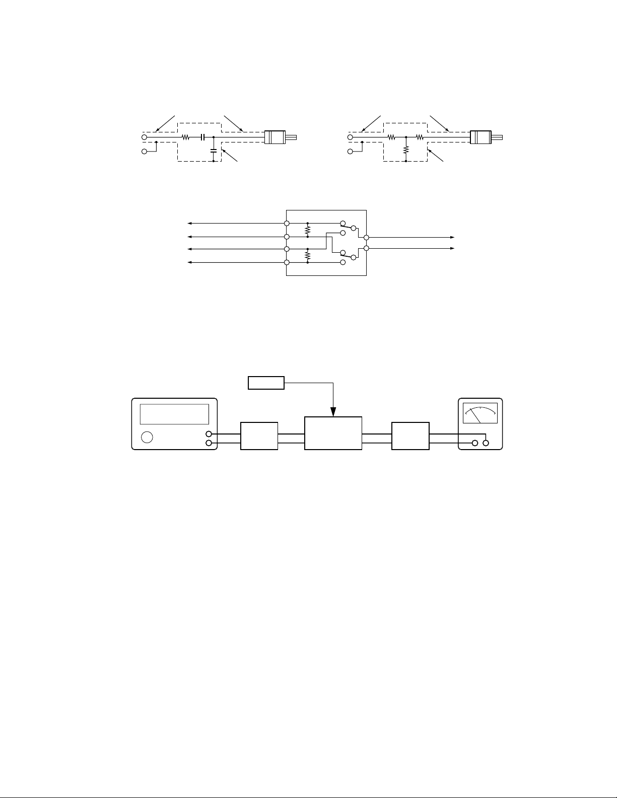
DUMMY BOX SCHEMATIC
ELECTRICAL ADJUSTMENTS
(FOR FXR-725GD)
AM S.G.
(50Ω)
CO-AX CABLE
33Ω 15PF
60PF
PLUG TO FIT ANTENNA
RECEPTACLE OF UNIT
METAL SHIELD CAN
FM S.G.
(50Ω)
CO-AX CABLE
10Ω 45Ω
60Ω
PLUG TO FIT ANTENNA
RECEPTACLE OF UNIT
METAL SHIELD CAN
AM DUMMY ANTENNA FM DUMMY ANTENNA
Fig. 1-1 Fig. 1-2
4Ω 20W
LEFT CHANNEL OUTPUT
UNIT
RIGHT CHANNEL OUTPUT
4Ω 20W
L
R
L
R
AC V.T.V.M. OR SCOPE
DUMMY LOAD & SWITCH BOX (FOR STEREO UNIT)
Fig. 1-3
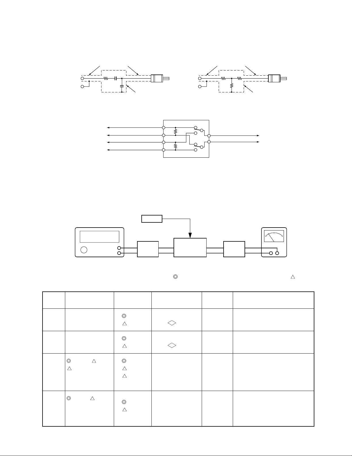
ALIGNMENT OF AM RF & lF SECTI0N
Set the radio for AM reception. AM signal generator should be coupled with antenna receptacle through dummy (see Fig.1-1).
Set VOLUME control to maximum and TONE to center. Attenuate signal generator output to maintain 0.5 watts (1.4 volts across
4 ohms load) on AC voltmeter.
VTVM
DISTORTION METER
AC VOLTMETER
T.P
SET
(See Fig. 1.3)
DUMMY
LOAD &
SW BOX
FM SG
&
STEREO SG
(See Fig. 1.2)
FM
DUMMY
ANTENNA
Fig. 2 * SG frequency should be as accurate as possible.
For RADIO DIAL SETTING in the table below , settings marked are for the (10 kHz step) mode and those marked are for the
(9 kHz step) mode.
STEP
1
2
3
4
GENERATOR
FREQUENCY
Non-Mod.
Non-Mod.
1000kHz, 999kHz
612kHz
400Hz, 30% MOD
SG att: Less than 17dB
610kHz, 612kHz
400Hz, 30% MOD
SG att: 17dB
RADIO DIAL
SETTING
530kHz
531kHz
1710kHz
1602kHz
1000kHz
999kHz
612kHz
610kHz
612kHz
OUTPUT
INDICATOR
DC VTVM to test
VT
point
DC VTVM to test
VT
point
AC VTVM across
speaker(L or R) or 4
ohms load
AC VTVM across
speaker(L or R) or 4
ohms load
ADJUST-
MENT
L134
AM OSC
—
L152
AM IF
L133
AM RF
REMARKS
Adjust for 1.4V. (TYP)
Check the voltage less than 7.5V.
Adjust for Maximum Level.
Adjust for Maximum Level.
— 2 —
Page 5
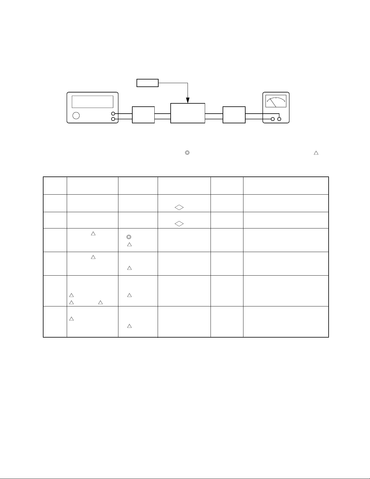
ALIGNMENT OF FM RF & IF SECTION
Set the radio for FM reception. FM signal generator should be coupled with antenna receptacle, through dummy (see Fig.1-2).
FM SG
&
STEREO SG
VTVM
(See Fig. 1.2)
FM
DUMMY
ANTENNA
T.P
SET
(See Fig. 1.3)
DUMMY
LOAD &
SW BOX
DISTORTION METER
AC VOLTMETER
Fig. 3 * SG frequency should be as accurate as possible.
For RADIO DIAL SETTING in the table below, settings marked are for the (200 kHz step) mode and those marked are for
the (50 kHz step) mode.
In steps 1 to7, no mark frequency means that is common for both (200 kHz step) and (50 kHz step) mode.
STEP
1
2
3
4
5
6
GENERATOR
FREQUENCY
Non-Mod.
Non-Mod.
98.1MHz, 97.1MHz
1kHz, 75kHz dev.
SG att:66dB (1mV)
98.1MHz, 97.1MHz
1kHz, 22.5kHz dev .
SG att:Less than 8dB
88.5 MHz
SG att: 8~12dB
87.5 MHz
97.1 MHz, 11dB
98.1MHz, 107.1MHz
88.5 MHz
SG att: 1 1dB
RADIO DIAL
SETTING
87.5MHz
87.5MHz
98.1MHz
97.1MHz
98.1MHz
97.1MHz
88.5 MHz
87.5 MHz
97.1MHz
98.1 MHz
107.1 MHz
88.5MHz
OUTPUT
INDICATOR
DC VTVM to test
VT
point
DC VTVM to test
VT
point
AC VTVM across
speaker or 4 ohms
load
AC VTVM across
speaker or 4 ohms
load
AC VTVM across
speaker or 4 ohms
load
AC VTVM across
speaker or 4 ohms
load
ADJUST-
MENT
L105
FM OSC
(L105)
L151
FM DET
L104
FM IFT
L101
FM ANT
L103
FM RF
L101
FM ANT
L103
FM RF
REMARKS
Adjust for 7.3V.
Check the voltage more than 1.1V.
Adjust for Minimum Distortion.
Adjust for Maximum Level.
Adjust for Maximum Level.
(Adjust for Minimum Distortion.)
Check for SPEC.
— 3 —
Page 6
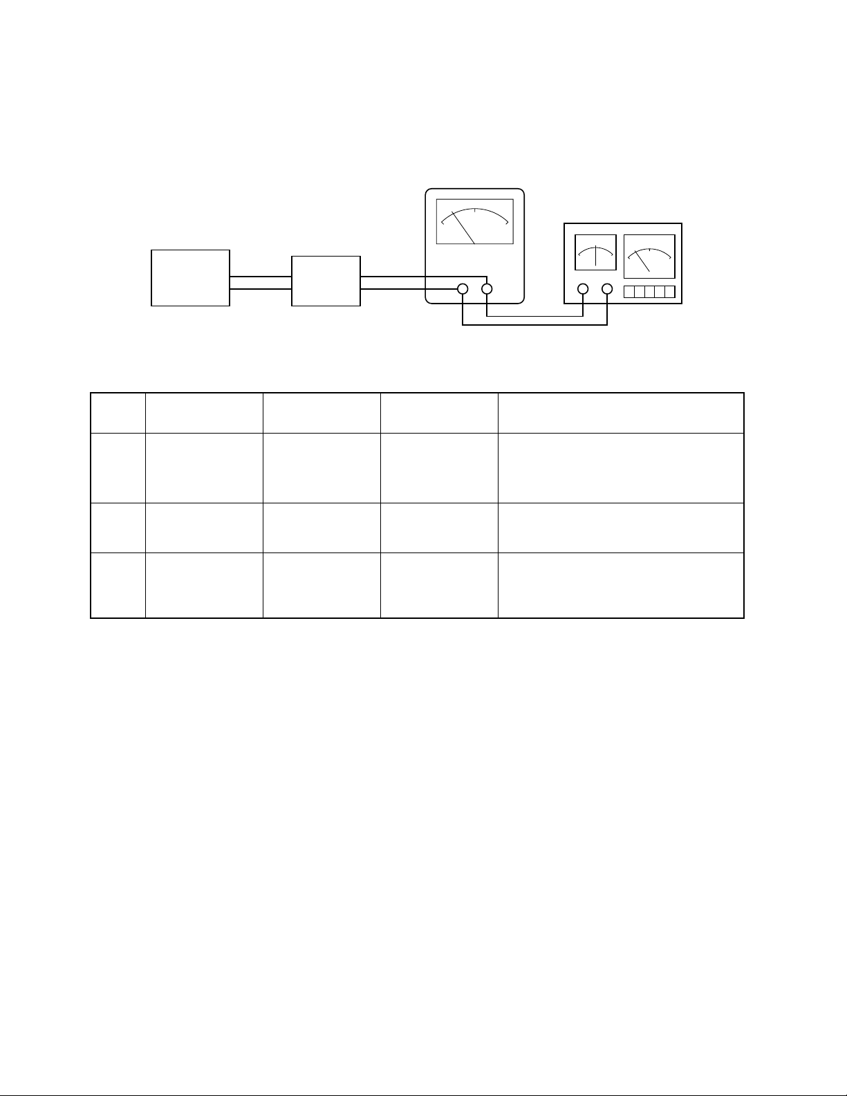
ALIGNMENT OF CASSETTE PLAYER
See the wow/flutter meter for JIS/WRMS function.
(See Fig. 1.3)
SET
DUMMY
LOAD &
SW BOX
AC VOLTMETER
Fig. 4
WOW/FLUTTER METER
(with drift meter)
STEP
1
2
3
MODULATION
FREQUENCY
Head Azimuth
Wow/Flutter
Tape Speed
TEST TAPE
MTT-257E
MTT-111N
(3kHz)
MTT-111N
(3kHz)
OUTPUT
INDICATOR
VOLTMETER
Wow/Flutter Meter
Tape Speed Drift
Meter
REMARKS
Align azimuth (on Head) for maximum
output 10 kHz as well as baiance on 1 kHz
between Left and Right channel output.
Check the display less than 0.3%
(JIS/WRMS).
Check the display within -1% and +3%.
— 4 —
Page 7
(FOR FXR-730GD/A.SS, FXC-750GD/A.SS, FXC-755RDS/XE)
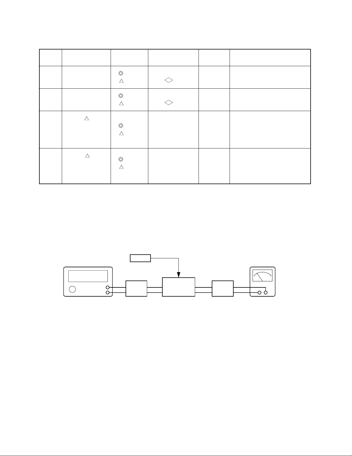
DUMMY BOX SCHEMATIC
ELECTRICAL ADJUSTMENTS
AM S.G.
(50Ω)
CO-AX CABLE
33Ω 15PF
60PF
PLUG TO FIT ANTENNA
RECEPTACLE OF UNIT
METAL SHIELD CAN
FM S.G.
(50Ω)
CO-AX CABLE
10Ω 45Ω
60Ω
PLUG TO FIT ANTENNA
RECEPTACLE OF UNIT
METAL SHIELD CAN
AM DUMMY ANTENNA FM DUMMY ANTENNA
Fig. 5-1 Fig. 5-2
4Ω 20W
LEFT CHANNEL OUTPUT
UNIT
RIGHT CHANNEL OUTPUT
4Ω 20W
L
R
L
R
AC V.T.V.M. OR SCOPE
DUMMY LOAD & SWITCH BOX (FOR STEREO UNIT)
Fig. 5-3
ALIGNMENT OF AM RF & lF SECTI0N
Set the radio for AM reception. AM signal generator should be coupled with antenna receptacle through dummy (see Fig.5-1).
Set VOLUME control to maximum and TONE to center. Attenuate signal generator output to maintain 0.5 watts (1.4 volts across
4 ohms load) on AC voltmeter.
VTVM
DISTORTION METER
AC VOLTMETER
FM SG
&
STEREO SG
(See Fig. 1.2)
FM
DUMMY
ANTENNA
T.P
SET
(See Fig. 1.3)
DUMMY
LOAD &
SW BOX
Fig. 6 * SG frequency should be as accurate as possible.
— 5 —
Page 8
STEP
GENERATOR
FREQUENCY
RADIO DIAL
SETTING
OUTPUT
INDICATOR
ADJUST-
MENT
REMARKS
1
Non-Mod.
2
Non-Mod.
3
1000kHz, 999kHz
400Hz
30% MOD
SG att: 20dBµ
4
1000kHz, 999kHz
400Hz
30% MOD
SG att: 30dBµ
530kHz
531kHz
1710kHz
1602kHz
1000kHz
999kHz
1000kHz
999kHz
TEST MODE
DC VTVM to test
VT
point
DC VTVM to test
VT
point
AC VTVM across
speaker(L or R) or 4
ohms load
Adjust so that the
“ST” mark of LCD
Display appears
—
—
L108
AM IF
L111
AM IFT2
R124
AM SD
Check the voltage more than 2.5V.
Check the voltage less than 7.5V.
Adjust for Maximum Level.
Sensitivity of the seeking frequency.
SETTING UP TEST MODE AT STEP 4 - SEE PAGE 9
ALIGNMENT OF FM RF & IF SECTION
Set the radio for FM reception. FM signal generator should be coupled with antenna receptacle, through dummy (see Fig.5-2).
FM SG
&
STEREO SG
VTVM
(See Fig. 1.2)
FM
DUMMY
ANTENNA
DISTORTION METER
AC VOLTMETER
T.P
SET
(See Fig. 1.3)
DUMMY
LOAD &
SW BOX
Fig. 7 * SG frequency should be as accurate as possible.
— 6 —
Page 9
STEP
GENERATOR
FREQUENCY
RADIO DIAL
SETTING
OUTPUT
INDICATOR
ADJUST-
MENT
REMARKS
1
2
3
4
5
6
7
7’
RDS
Non-Mod.
Non-Mod.
98.1MHz
1kHz, 22.5kHz dev.
SG att:66dBµ(1mV)
98.1MHz
1kHz, 22.5kHz dev .
SG att:6dBµ
98.1MHz
SG att:6dBµ
87.5MHz
107.9 (108) MHz
SG att:6dBµ
98.1MHz
SG att:25dBµ
98.1MHz
1kHz, 22.5kHz dev .
SG att:33dBµ
87.5MHz
107.9MHz
108MHz
98.1MHz
98.1MHz
98.1MHz
87.5MHz
107.9 (108.0 ) MHz
98.1MHz
TEST MODE
98.1MHz
TEST MODE
DC VTVM to test
VT
point
DC VTVM to test
VT
point
AC VTVM to test
VT
point
AC VTVM across
speaker or 4 ohms
load
AC VTVM across
speaker or 4 ohms
load
AC VTVM across
speaker or 4 ohms
load
Adjust so that the
“ST” mark of LCD
Display appears
Adjust like to
appear for 0.95 of
LCD Display
—
L103
FM OSC
L110
FM DET
L107
FM MIX
L100
FM ANT
L102
FM RF
L100
FM ANT
L102
FM RF
R129
FM SD
R204
Check the voltage more than 1.1V
Adjust for 6.9 ± 0.1V.
NULL VOLTAGE to become
—20±20mV
Adjust for Maximum Level.
Adjust for Maximum Level.
Check for SPEC.
Sensitivity of the seeking frequency.
Sensitivity of the S meter.
SETTING UP TEST MODE AT STEP 7 - SEE PAGE 10
ALIGNMENT OF FM MULTIPLEX SECTION
FM signal generator should be modulated by FM stereo signal generator.
Modulation level: 19kHz 10% (7.5kHz dev)
1000Hz 30% (22.5kHz dev)
FM signal generator output level: 66dBµ (1mV)
Frequency: 98.1 MHz.
STEP
1
2
3
MODULATION
FREQUENCY
19kHz & 1000Hz
(Left Channel)
SG att:66dBµ
19kHz & 1000Hz
(Right Channel)
19kHz & 1000Hz
(Left Channel)
SG att:47dBµ
OUTPUT INDICATOR
AC VTVM across Right speaker or
Right channel load
AC VTVM through Left speaker or
Left channel load
AC VTVM across Right speaker or
Right channel load
Set the radio for FM reception and tune to signal. Adjust volume control to provide 0.5 watt on AC VTVM and tone to
center. Set L/R balance control for equal output at each channel.
ADJUST-
MENT
R137
R137
R156
Adjust for minimum.
Check for minimum.
Adjust for 20dB Separation.
REMARKS
— 7 —
Page 10
ELECTRICAL ADJUSTMENTS
FOR FXR-725GD, FXR-730GD FXC-750GD
SETTING UP TEST MODE AT STEP 4 FOR AM & STEP 7 FOR FM
Press the e
the mode to the test mode shown in Step 4 for AM and Step 7 for FM.
PWR
button to turn the power off. Next, use the following procedure with the front panel switches to set
VOL
REL
PWR
TUN
TRK
CD CHANGER CONTROL
HI-POWER 40W x 4 FXC-750GD
AUD
BAND/ATP
CDC
+
-
DISC
SCANRM/
RPTSHF
LD
LO
/DX
q we r
Fig. 5
1. While the power is off, press the q
to enable the w
BAND
button to be used at the moment the power comes on.
2. If the above operation is successful all the figures on the LCD light up, check that you have entered test mode. Fig. 6 (A).
3. Press the r
AUD
button once. The display shown in Fig. 6 (B) appears on the LCD and the unit enters DX mode.
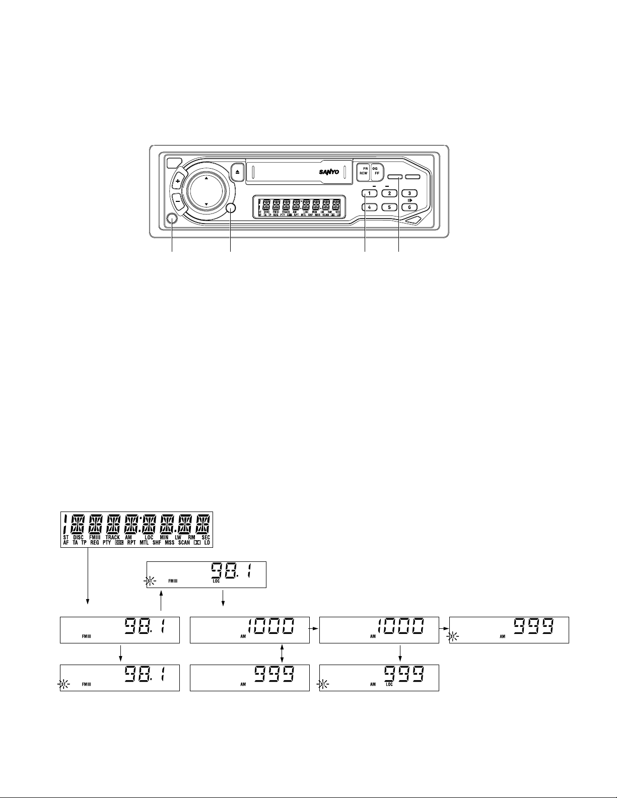
Then, while receiving FM 98.1MHz rotate the Semi-fixed VR R129 on the TUNER UNIT (RF33) to adjust the LCD until the
stereo mark light “
4. Press the r
ST
” is on. Fig. 6 (B').
AUD
button, if the display changes to that shown in Fig. 6 (C) the unit is in Local mode. Check that the “
mark is displayed (for specific: Input level is 12~28dB higher than that of the DX mode).
5. Press the w
6. Then press the r
BAND
button, if the display changes to that shown in Fig. 6 (D) or (D') receiving AM1000 kHz or *(999) kHz.
AUD
button, if the display changes to that shown in Fig. 6 (E) the unit is in DX mode. Rotate the Semi-
fixed VR R124 on the TUNER UNIT (RF33) to adjust the LCD until “
7. Then press the r
AUD
button, if the display changes to that shown in Fig. 6 (F) the unit is in Local mode. Check that the “ST”
mark is displayed. (for specific: Input level is 12~28dB higher than that of DX mode).
8. Turn off the power to release the test mode.
PRESET1
button. Then press the w
ST
BAND
button and e
” mark lights up.
PWR
button simultaneously
ST
”
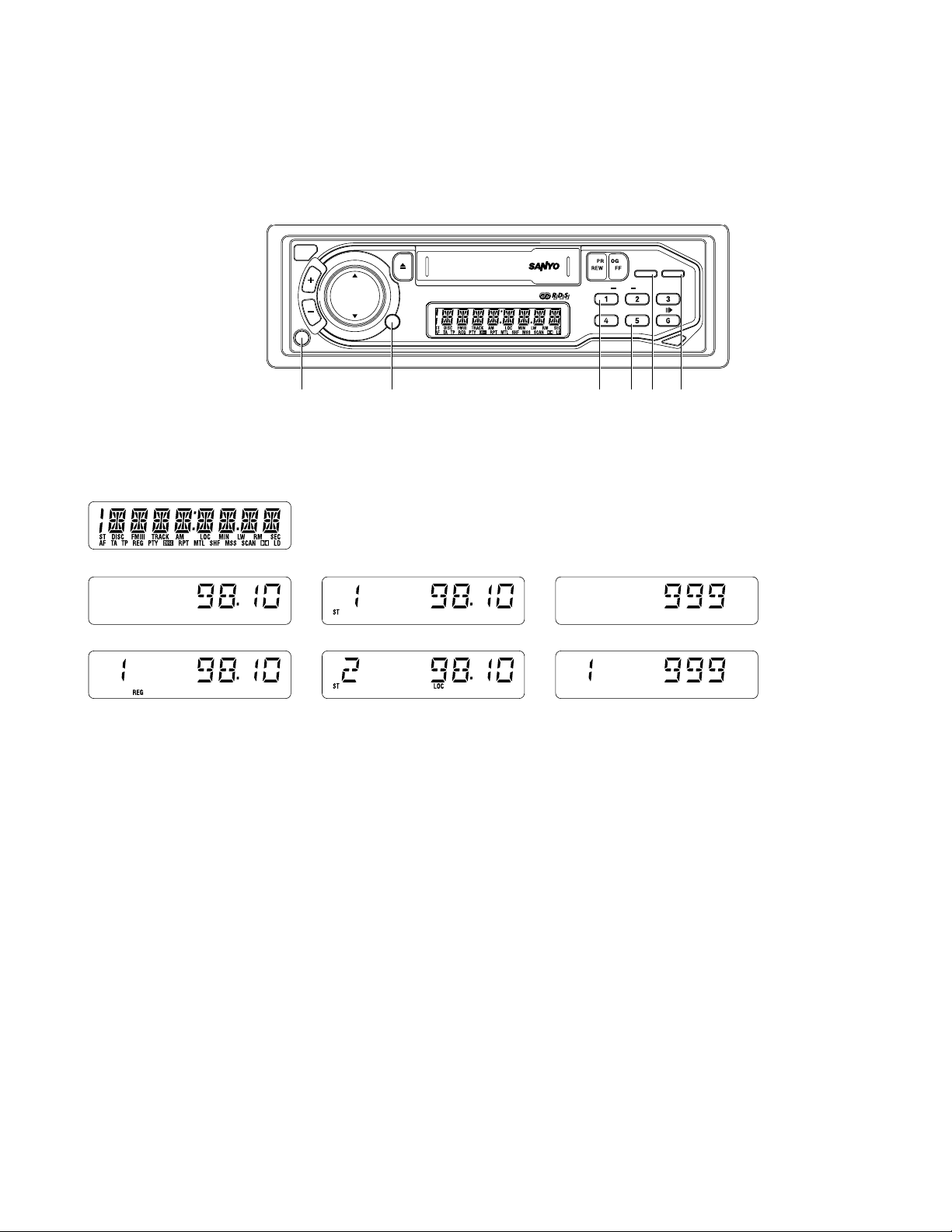
TEST MODE CHART
(A) Enter the Test Mode
(B) FM DX Mode
(B’)OK
(C) FM Local Mode OK
(D) Receiving 1000kHz
(D’) Receiving 999kHz
(E) AM DX Mode
(F) AM Local Mode
Fig. 6
— 8 —
(E’)OK
Page 11
ELECTRICAL ADJUSTMENTS
FOR FXC-755RDS
TEST MODE CHART
(A) Enter the Test Mode
(B) Enter the FM Mode
(C) FM DX Mode
REL
VOL
TUN
TRK
CD
PWR
(D) Receiving 98.1 MHz
(E) FM Local Mode
CD CHANGER CONTROL
HI-POWER 40W x 4 FXC-755RDS
AUD
Fig. 7
BAND/ATP
TA/AF
+
-
DISC
SCANRM/
RPTSHF
q w tye r
(F) Enter the AM Mode
(G) AM DX Mode
PTY
REG
Fig. 8
1. While the power is off, press the q
PRESET1
button. Then keep pressing the w
BAND
button, press the e
simultaneously . All the figures on the LCD lights up Fig. 8 (A) enter the test mode.
2. Press the r
AUD
button after step 1, the unit enters FM seek adjustment mode of the DX mode. Fig. 8 (C) Rotate the R129
on the PC Board Ass’y (RF33R) to adjust the LCD until the STEREO indicator lights up Fig. 8 (D).
AUD
3. Press the r
button again after step 2, the unit enters the LOCAL mode. Check that the STEREO indicator is displayed
(for specific: Input level of signal Generator is 12~28dB higher than that of the DX mode). Fig. 8 (E)
4. By pressing the w
5. Press the r
BAND
button in the steps 1 to 3 enters the unit to the AM mode. Fig. 8 (F)
AUD
button, the unit enters SEEK adjustment mode of the DX mode. Fig. 8 (G)
Rotate the R124 on the PC Board Ass’y (RF33R) to adjust the LCD until the STEREO indicator lights up.
AUD
6. Pressing the r
button again after the step 5, the unit enters the LOCAL mode. Check that the STEREO indicator is
displayed (for specific: Input level of Signal Generator is 12~28dB higher than that of the DX mode). Fig. 9 (I)
PWR
button
— 9 —
Page 12
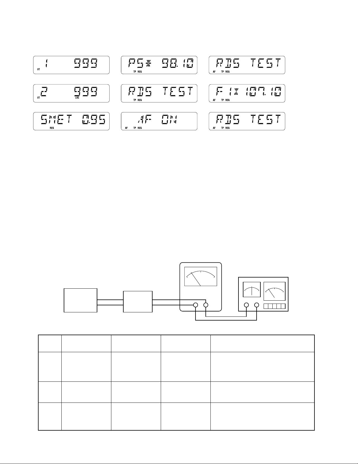
(H) Receiving 999 kHz (K) The moment TP ON (N) Change the Display while AF ON
(I) AM Local Mode
(J) S. Meter Adj. Mode
(L) Change the Display while TP ON
(M) The Moment AF ON
Fig. 9
7. Press the t
TA/AF
button in the step 1, the unit enters the S meter adjustment mode. Rotate the R204 on Main PCB to adjust the LCD
until the 0.95 lights up Fig. 9 (J)
8. e
9. e
POWER
POWER
OFF and ON. Release the test mode.
ON and press the y
PRESET 5
.
SG 98.1 MHz, MOD. 75 kHz, INT MOD. EXT, att 66dBµ
RDS 1.0%, MOD. 30% 1 kHz, MONO, RDS ON, TP ON, SK OFF, BK OFF.
10. Confirm the “
TP
” indicator on the LCD lights up.
Fig. 9 (K) 씮 (L) soon. So RDS ON Sensitivity is OK.
11 . Press the q
12. Press the t
PRESET 1
T A/AF
button for more than 2 seconds. (Memorize the RDS).
button for more than 2 seconds and confirm the “
SG 107.1 MHz, MOD. 75 kHz, INT MOD. EXT, att 66dBµ
RDS 1.6%, MOD. 30% 1kHz, MONO, RDS ON, TP ON, SK OFF, BK OFF.
13. Press the q
PRESET 1
button. Confirm the receiving 107.1 MHz automatically. So the LCD indicator displays Fig. 9 (O) 씮 (P) .
(O) The Moment 107.1MHz Receiving
Change the Display while 107.1MHz Receiving
(P)
AF
” indicator on the LCD lights up. Fig. 9 (M) 씮 (N) soon.
ALIGNMENT OF CASSETTE PLAYER
See the wow/flutter meter for JIS/WRMS function.
(See Fig. 1.3)
DUMMY
LOAD &
SW BOX
TEST TAPE
MTT-257E
MTT-111N
(3kHz)
MTT-111N
(3kHz)
STEP
1
2
3
SET
MODULATION
FREQUENCY
Head Azimuth
Wow/Flutter
Tape Speed
AC VOLTMETER
Fig. 4
OUTPUT
INDICATOR
VOLTMETER
Wow/Flutter Meter
Tape Speed Drift
Meter
WOW/FLUTTER METER
(with drift meter)
REMARKS
Align azimuth (on Head) for maximum
output 10 kHz as well as baiance on 1 kHz
between Left and Right channel output.
Check the display less than 0.3%
(JIS/WRMS).
Check the display within -1% and +3%.
— 10 —
Page 13
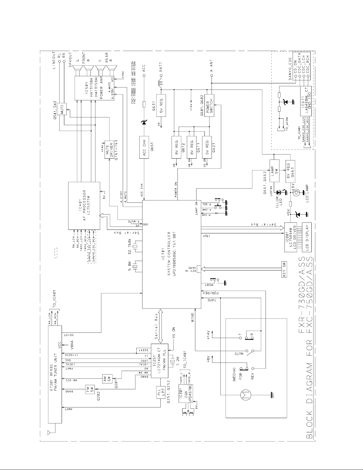
BLOCK DIAGRAM
: FXC-750GD only used
FOR FXR-725GD, FXR-730GD FXC-750GD
— 11 —
Page 14
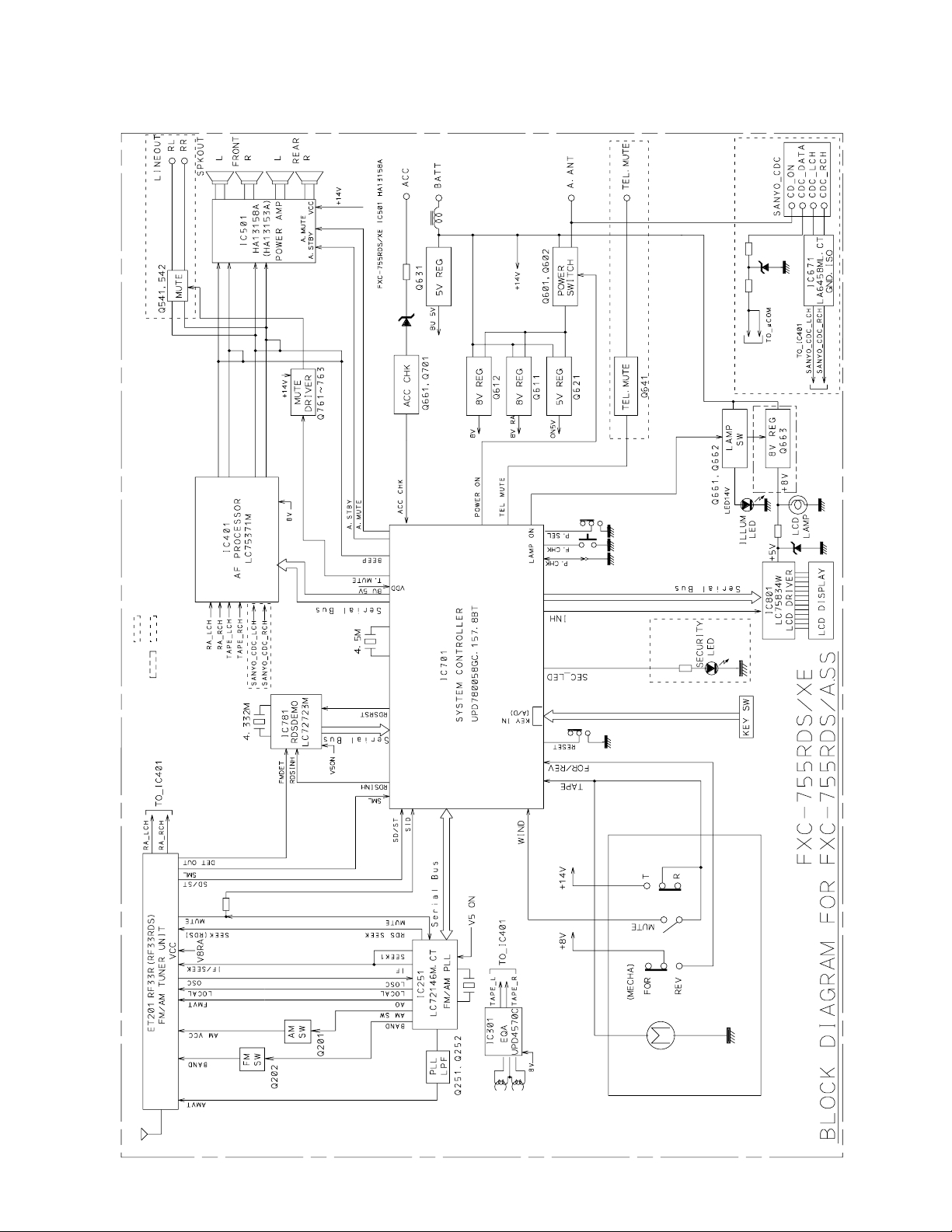
: FXC-755RDS/XE only used
: FXC-755RDS/A.SS only used
BLOCK DIAGRAM
FOR FXC-755RDS
— 12 —
Page 15
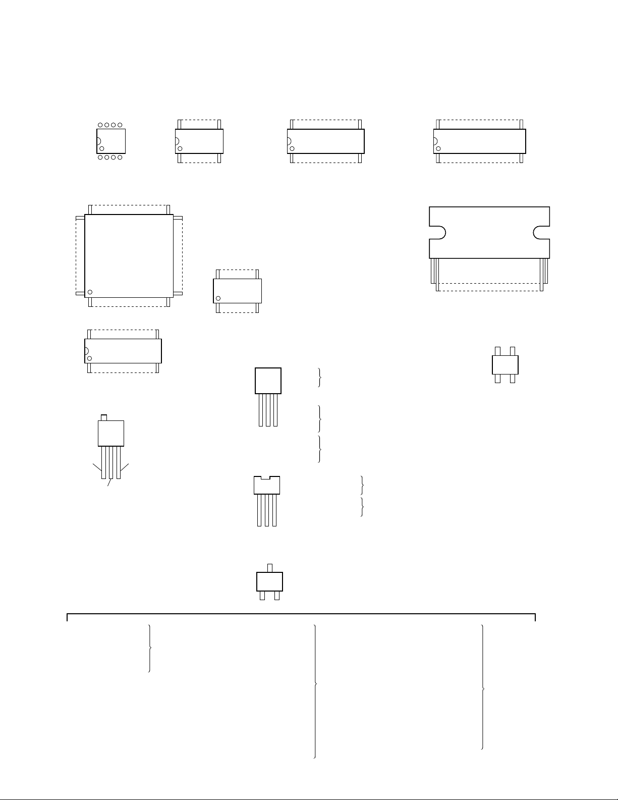
IC/TRANSISTOR LEAD IDENTIFICATION
TOP VIEW or SIDE VIEW
85
14
IC301 : UPC4570C IC280 : KA2272D-1-MF
60
61 40
80 21
1
24 13
112
IC251 : LC72146M
(FOR FXR-730GD/A.SS, FXC-755RDS/XE)
VDD
OUT
16 9
18
(FOR FXR-725GD)
41
IC701 : LC72323N-9931 (FOR FXR-725GD)
IC701 : UPD780058GC
(FOR FXR-730GD/ASS, FXC-750GD/A.SS,
FXC-750GD/A.SS, FXC-755RDS/XE)
85
20
14
IC671 : LA6458ML-CT
(FOR FXC-750GD/A.SS, FXC-755RDS/XE)
24 13
112
IC151 : BA1450S
(FOR FXR-725G)
Q331:
Q661:
Q660: KTA1272T(FOR FXR-725GD)
Q601:
Q701:
ECB
Q702:
Q612:
Q621:
Q631:
36 19
1
IC401 : LC7531M-CT
1 23
KTA1272T(FOR FXC-755RDS/XE)
KTC3199T(FOR FXR-725GD)
KTC3199T(FOR FXR-730GD/A.SS,
FXC-750GD/A.SS, FXC-755RDS/XE)
18
IC501 : HA13153A
G2 G1
DS
Q101: 3SK126T
(FOR FXR-725GD)
GND
IC702: BMR-0101E-RT
(FOR FXR-730GD/A.SS,
FXC-755RDS/XE)
Q100 : 2SA1037AKT
Q131 : DTC124EKAT
Q133 : DTA114EKAT
Q134 : 2SC2412KT
Q135 : 2SC3624T
FOR FXR-725GD
Q602 : 2SD1858T
Q604 : 2SB1326T
Q601 : 2SB1326T
Q611 : 2SD1858T
ECB
C
B
E
Q201 : UN2112TX
Q202 : UN2112TX
Q251 : 2SC2412KT
Q252 : 2SC2412KT
Q651 : 2SC2412KT
Q332 : UN2212TX
Q602 : UN2212TX
Q641 : UN2212T X
Q662 : UN2212TX
Q791 : UN2212TX
Q792 : UN2212TX
Q541 : DTC143TKAT
Q542 : DTC143TKAT
Q793 : 2SA1037AKT
(FOR FXR-725GD)
(FOR FXC-755RDS/XE)
FOR FXC-755RDS/XE
Q201 : UN2112TX
Q202 : UN2112TX
Q662 : UN2112TX
Q251 : 2SC2412KT
Q252 : 2SC2412KT
Q651 : 2SC2412KT
Q332 : UN2212TX
Q602 : UN2212TX
Q791 : UN2212TX
Q792 : UN2212TX
Q541 : DTC143TKAT
Q542 : DTC143TKAT
Q793 : 2SA1037AKT
FOR FXR-730GD/A.SS,
FXC-750GD/A.SS
— 13 —
Page 16
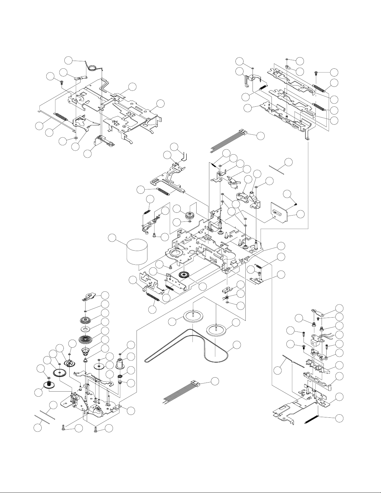
CASSETTE DECK MECHANISM EXPLODED VIEW
(MECHANISM #5AD002)
1
2
3
9
10
4
5
6
7
8
35
36
43
37
38
33
34
39
40
64
56
63
57
65
66
62
67
68
61
60
93
59
58
53
55
95
69
70
54
71
72
73
74
75
23
95
22
21
20
95
19
18
11
12
13
14
15
16
17
28
29
30
3255
24
25
26
27
31
44
42
45
41
46
48
47
94
48
49
52
51
50
91
78
90
92
76
77
87
89
88
86
85
84
83
82
81
80
79
* When repairing any of the numerous precision parts in the cassette deck mechanism, a high degree of skill is necessory and
the cost of parts may not necessarily be cheaper than for the whole mechanism.
In addition, parts from the deck mechanism exploded view and parts list are only for technical reference. These parts may or
may not be individually available.
— 14 —
Page 17
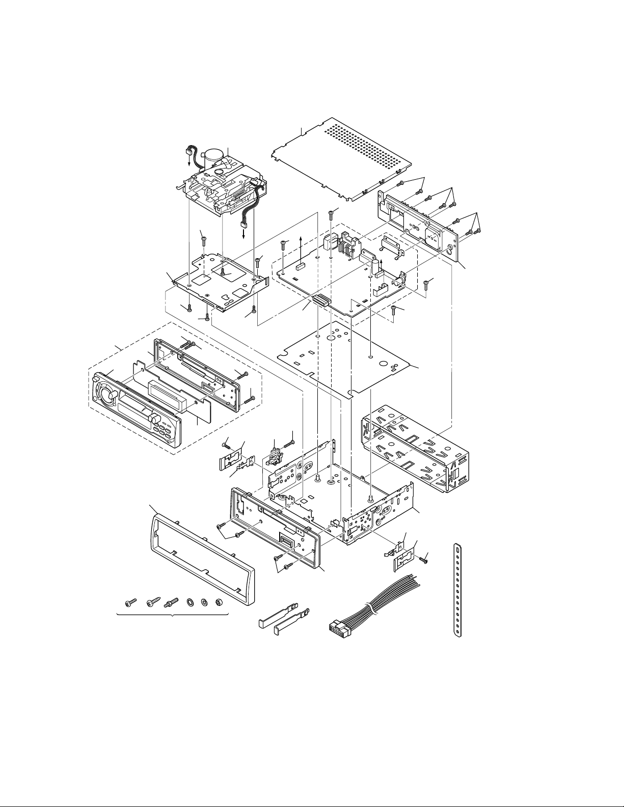
CABINET & CHASSIS EXPLODED VIEW
(FXR-725GD)
e
q
!4
!5
!6
r
!0
!8
A
!1
!0
!7
!2
!8
!8
@2
B
!2
!0
!0
!8
@1
u
!1
!8
A
B
!9
!1
o
!2
!1
!2
!2
t
@3
SCREW KIT (6PCS)
TK29X12210
!3
i
!3
BKT (REL)
TK21176780
@0
CABLE ASS'Y
(FOR FXR-725GD/XE)
TK26917002
(FOR FXR-725GD/SS, A.SS)
TK26917170
BRACKET (MOUNT)
TK21176533
y
i
@1
@2
SUPPORT BKT
TK2102013
— 15 —
Page 18
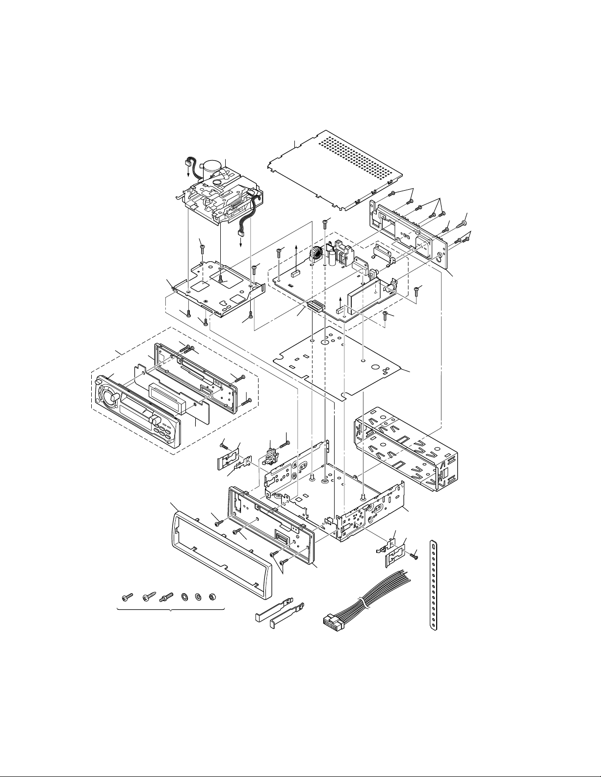
CABINET & CHASSIS EXPLODED VIEW
(FXR-730GD/ASS, FXC-750GD/ASS, FXC-755RDS/XE)
e
q
!4
!5
!6
r
!0
!8
A
!1
!7
!2
!0
!8
!8
@2
B
!2
!0
!0
!8
@1
u
!8
!1
A
B
!9
!1
o
!2
!1
!2
!2
w
!2
t
@3
SCREW KIT (6PCS)
TK29X12210
!3
i
!3
BKT (REL)
TK21176780
!3
— 16 —
@0
CABLE ASS'Y
(For FXR-730GD/A.SS,
FXC-750GD/A.SS)
TK26917170
(For FXC-755RDS/XE)
TK26917280
BRACKET (MOUNT)
TK21176533
y
i
@1
@2
SUPPORT BKT
TK2102013
Page 19

PARTS LIST
CABINET & CHASSIS
Ref. No. Part No. Description
1 TK5AD002 DECK MECHANISM (ADC2345BDS)
2 TK2953310A DPBB-3X10SSA
3 TK21046350 COVER (TOP)
4 TK21102320 DECK BRACKET
5 TK21145031 HEATSINK (MITSUMI) (FXR-725GD/A.SS, SS, XE)
TK21145230 HEATSINK (2P) (FXR-730GD/A.SS)
TK21145240 HEATSINK (2P-CDC) (FXC-750GD/A.SS, FXC-755RDS/XE)
6 TK21035093 CHASSIS ASSY (CST)
7 TK21176550 BRACKET ASSY (DET)
8 TK21291290 PLATE SPRING (REL)
9 TK28061360 INSULATOR (PCB)
10 TK2912304A APPM-3X4SSA
11 TK2952265A DPBS-2.6X5SSA
12 TK2952266A DPBS-2.6X6SSA
13 TK2952266C DPBS-2.6X6SSC
14 TKAKC420G9C FPPART FXR725GD/SSSOP (FXR-725GD/A.SS, FXR-725GD/SS)
TKAKC421G9C FPPART FXR725GD/XESOP (FXR-725GD/XE)
TKAKC401G9C FPPART FXR730GD/ASSSOP (FXR-730GD/A.SS)
TKAKC403G9C FPPART FXC750GD/SSSOP (FXC-750GD/A.SS)
TKAKC422G9C FPPART FXC755RDS/XESOP (FXC-755RDS/XE)
15 TK22331630 FPASSY(A) (FXR-725GD/XE)
TK22331730 FPASSY(A) (FXR-725GD/SS, A.SS)
TK22331341 FPASSY(A) (FXR-730GD/A.SS)
TK22331321 FPASSY(A) (FXC-750GD/A.SS)
TK22331700 FPASSY(A) (FXC-755RDS/XE)
16 TK22240240 FACE PLATE(B) (FXR-725GD/ASS, SS, XE, FXR-730GD/A.SS,
FXC-750GD/A.SS, FXC-755RDS/XE)
17 TK35U95B0 DISP CIRCUIT BOARD (FXR-725GD/A.SS, SS, XE)
TK35U42B0 DISP CIRCUIT BOARD (FXR-730GD/A.SS, FXC-750GD/A.SS)
TK35V01B0 DISP CIRCUIT BOARD (FXC-755RDS/XE)
18 TK29A5208C TPB2-2X8SSC
19 TK35U94A0 MAIN CIRCUIT BOARD (FXR-725GD/A.SS, SS, XE)
TK35V09A0 MAIN CIRCUIT BOARD (FXR-730GD/A.SS)
TK35V10A0 MAIN CIRCUIT BOARD (FXC-750GD/A.SS)
TK35V00A0 MAIN CIRCUIT BOARD (FXC-755RDS/XE)
TK37306B0 BL ASSY RF33S (FXR-730GD/A.SS, FXC-750GD/A.SS)
TK37303B0 BL ASSY RF33R (FXC-755RDS/XE)
20 TK22331640 FPASSY (C) (FXR-725GD/A.SS, SS, XE, FXR-730GD/A.SS)
TK22331750 FPASSY (C) (FXC-750GD/A.SS)
TK22331710 FPASSY (C) (FXC-755RDS/XE)
21 TK21176820 BRACKET (STOPPER)
22 TK2958266A DPSS-2.6X6SSA
23 TK22060460 ESC ADAPTOR (SANYO) (FXR-725GD/XE, FXC-755RDS/XE)
TK22060450 ESC ADAPTOR (E-1.5) (FXR-725GD/SS, A.SS, FXR-730GD/A.SS,
FXC-750GD/A.SS)
— 17 —
Page 20

ACCESSORIES
Ref. No. Part No. Description
— TK2102013 SUPPORT BKT
— TK21176533 BKT (MOUNT)
— TK21176780 BKT (REL)
— TK22720821 C.CASE ASSY(FXR-725GD/SS, FXR-730GD/A.SS, FXC-750GD/A.SS,
FXC-755RDS/XE)
— TK26917002 CABLE ASSY (FXR-725GD/XE)
TK26917170 CABLE ASSY (E-1) (FXR-725GD/SS, A.SS, FXR-730GD/A.SS,
FXC-750GD/A.SS)
TK26917280 CABLE ASSY FXD-ISO (FXC-755RDS/XE)
— TK28585380 GIFT BOX (FXR-725GD/SS, A.SS)
TK28530930 IN BOX (FXR-725GD/XE)
TK28584910 GIFT BOX (FXR-730GD/A.SS)
TK28584920 GIFT BOX (FXC-750GD/A.SS)
TK28530940 IN BOX (FXC-755RDS/XE)
— TK28940610 M.KIT (FXR-725GD/SS, A.SS)
TK28940550 M.KIT(FXR-725GD/XE, FXR-730GD/A.SS, FXC-750GD/A.SS,
FXC-755RDS/XE)
— TK29X12210 SCREW KIT
— 18 —
Page 21

CASSETTE DECK MECHANISM (5AD002)
Ref. No. Part No. Description
1 TK6107-000323 SPRING-F
2 TKMT75-00047X ASS’Y CASE L/P
3 TK6003-000305 SCREW (M2x4)
4 TK6107-000369 SPRINF L/P
5 TK6107-000339 SPRING E/P
6 TK6031-000446 WASHER(1.6x3.5x0.25T)
7 TKMT70-00439B CASE E/P
8 TKMT72-00027A ARM-C
9 TKMT70-00076A CASE CASSETTE
10 TKMT70-00438T HOLDER-C
11 TKMT90-11011A ASS’Y ARM PLAY
12 TK6031-001032 WASHER (1x3.2x0.25T)
13 TKMT72-00331N GEAR CLUTCH 1
14 TKMT74-00091C FELT CLUTCH
15 TKMT72-00331P GEAR CLUTCH 2
16 TK6107-001021 SPRING CLUTCH
17 TKHT72-00046A CLUTCH BODY
18 TK6031-000575 WASHER (1.2x3.5x0.5T)
19 TKMT72-00331M GEAR CAM
20 TK6031-000431 WASHER (1.2x3x0.25T)
21 TKMT66-00025A GEAR SENSOR
22 TK6031-000431 WASHER (1.2x3x0.25T)
23 TKMT66-00017A GEAR 19.6B
24 TK6031-000433 WASHER (1.2x3.2x0.35T)
25 TKMT72-00379D GEAR REEL
26 TKMT72-00126A SENSOR PULLEY
27 TK6107-000191 SPRING B/T
28 TK6031-000431 WASHER (1.2x3x0.25T)
29 TKMT72-00379C GEAR PLAY-B
30 TKMT72-00331G ARM SENSOR
31 TKMT75-00047K ASS’Y CHASSIS REEL
32 TK6003-000305 SCREW (M2x4)
33 TKMT61-00002A SPRING SWITCH
34 TKMT70-00438Z LEVER SWITCH
35 TK6107-001061 SPRING TRIGGER
36 TK6107-000249 SPRING ARM LOCK
37 TKMT72-00380G ARM LOCK
38 TK6009-000333 SCREW ARM LOCK
39 TKMT72-00104A PULLEY CENTER
40 TK6031-000431 WASHER (1.2x3x0.25T)
41 TK6001-001048 SCREW (M2x2.5)
42 TKMT75-00047U ASS’Y-EJECT A C/K
43 TKMT90-11010N ASS’Y MOTOR
44 TKMT70-00438R LEVER EJECT-B
45 TK6107-001023 SPRING EJECT-B
46 TK6107-001022 SPRING EJECT-A
47 TKMT66-00016A GEAR 18.6B
48 TKMT91-01011K ASS’Y FLYWHEEL
49 TK6602-000106 BELT (120.2)
— 19 —
Page 22

CASSETTE DECK MECHANISM (5AD002)
Ref. No. Part No. Description
50 TK6031-001082 WASHER (2.1x5x0.5T)
51 TK6107-001028 SPRING LEVER PLAY
52 TKMT70-00438W LEVER PLAY
53 TKMT90-02013J ASS’Y CHASSIS MAIN
54 TKMT91-21013R ASS’Y PCB HEAD
55 TK6003-000322 SCREW (2x3.7)
56 TK6031-000464 WASHER (1.9x3.2x0.25)
57 TK6044-000272 E-RING (ø1.5)
58 TK6031-000486 WASHER (2.1x4x0.4T)
59 TKMT90-11010P ASS’Y ARM C/R
60 TKMT90-15010E ASS’Y PINCH R
61 TKMT90-15010D ASS’Y PINCH F
62 TKMT70-00438P LEVER PRO
63 TK6031-000486 WASHER (2.1x4x0.4T)
64 TK6107-001026 SPRING LEVER PRO
65 TK6031-000430 WASHER (1.2x3.2x0.35T)
66 TKMT70-00438Y LEVER LOCK
67 TK6107-001048 SPRING LEVER LOCK
68 TKMT75-00047V ASS’Y BASE FR C/K
69 TK6031-001082 WASHER (2.1x5x0.5T)
70 TKMT72-00379E STOPPER LEVER
71 TK6003-000305 SCREW (M2x4)
72 TK6107-001054 SPRING FF/REW
73 TKMT70-00487Q LEVER FF
74 TK6107-001054 SPRING FF/REW
75 TKMT70-00487R LEVER REWIND
76 TK6009-000334 SCREW AZIMUTH
77 TK6003-000295 SCREW (M2x5.5)
78 TK6107-000366 SPRING PINCH
79 TK6107-001049 SPRING BASE HEAD
80 TKMT90-02013H ASS’Y BASE HEAD C/K
81 TKMT72-00331K PLATE HEAD-B
82 TKMT72-00056A HOLDER H/B
83 TKMT72-00079A PLATE HEAD-A
84 TK6009-000334 SCREW AZIMUTH
85 TKMT59-00052A HEAD (TC860CPRF)
86 TK6107-000345 SPRING AZIMUTH-R
87 TK6107-000201 SPRING AZIMUTH-F
88 TK6002-001011 SCREW (M2x3)
89 TKMT70-00438A ST OPPER AZIMUTH
90 TKMT61-00007A SPRING EJECT
91 TKMT60-00025A SCREW (Ml.7x2)
92 TKMT70-00487U EJECT STOPPER
93 TKMT41-00160B HEAD CONNETOR ASS’Y
94 TKMT41-00160A MOTOR CONNECTOR ASS’Y
95 TKMT71-00099A NyIon Tube (L-40mm)
— 20 —
Page 23

MAIN CIRCUIT BOARD FOR FXR-725GD/SS, A.SS, XE
Ref. No. Part No. Description
AJ100 TK196510300 ANT JACK ASSY
C101, C172 TK15711000J CAPACITOR, CHIP, 10PF 50V
C102, C118 TK15711R00J CAPACITOR, CHIP, 1PF 50V
C103, C106 TK157A1020J CAPACITOR, CHIP, 1000PF 50V
C104, C108 TK15715R00J CAPACITOR, CHIP, 5PF 50V
C105, C117 TK157A1030J CAPACITOR, CHIP, 0.01UF 50V
C107, C137 TK157A2230J CAPACITOR, CHIP, 0.022UF 25V
C109 TK15713300J CAPACITOR, CHIP, 33PF 50V
C110 TK15712R00J CAPACITOR, CHIP, 2PF 50V
C111, C113 TK15715R00J CAPACITOR, CHIP, 5PF 50V
C112, C309 TK157C1040J CAPACITOR, CHIP, 0.1U
C114, C120 TK157A1020J CAPACITOR, CHIP, 1000PF 50V
C115, C156 TK1553106K6 CAPACITOR, ELECTROLYTIC, 10UF 16V
C116 TK15711800J CAPACITOR, CHIP, 18PF 50V
C119 TK15713900J CAPACITOR, CHIP, 39PF 50V
C131, C132 TK157A1020J CAPACITOR, CHIP, 1000PF 50V
C133, C203 TK157A1030J CAPACITOR, CHIP, 0.01UF 50V
C134, C141 TK157A1020J CAPACITOR, CHIP, 1000PF 50V
C136, C184 TK15715R00J CAPACITOR, CHIP, 5PF 50V
C138, C152 TK157A2230J CAPACITOR, CHIP, 0.022UF 25V
C139 TK15743610E CAPACITOR, CHIP, 360P
C140 TK15711500J CAPACITOR, CHIP, 15PF 50V
C142, C510 TK155610525 CAPACITOR, ELECTROLYTIC, 1UF 50V
C143, C202 TK1553476G6 CAPACITOR, ELECTROLYTIC, 47UF 16V
C144, C147 TK157A1040J CAPACITOR, CHIP, 0.1UF 16V
C145, C146 TK157A1020J CAPACITOR, CHIP, 1000PF 50V
C148 TK157A4730J CAPACITOR, CHIP, 0.047UF 16V
C149 TK157A1020J CAPACITOR, CHIP, 1000PF 50V
C151 TK1552107K6 CAPACITOR, ELECTROLYTIC, 100UF 10V
C153, C162 TK1556105K6 CAPACITOR, ELECTROLYTIC, 1UF 50V
C154 TK1556224K6 CAPACITOR, ELECTROLYTIC, 0.22UF 50V
C155, C163 TK157A2230J CAPACITOR, CHIP, 0.022UF 25V
C158 TK157C1050J CAPACITOR, CHIP, 1UF 10V
C159 TK157A1230J CAPACITOR, CHIP, 0.012U
C160, C603 TK15711010J CAPACITOR, CHIP, 100PF 50V
C161 TK1553226K5 CAPACITOR, ELECTROLYTIC, 22UF 16V
C164 TK1552107G5 CAPACITOR, ELECTROLYTIC, 100UF 10V
C170, C289 TK15713310J CAPACITOR, CHIP, 330PF 50V
C171, C296 TK157A2230J CAPACITOR, CHIP, 0.022UF 25V
C182 TK157A1520J CAPACITOR, CHIP, 1500PF 50V
C204, C205 TK157A2730J CAPACITOR, CHIP, 0.027UF 25V
C280, C292 TK1556105K6 CAPACITOR, ELECTROLYTIC, 1UF 50V
C282, C283 TK15716810J CAPACITOR, CHIP, 680PF 50V
C284 TK157A1220J CAPACITOR, CHIP, 1200PF 50V
C285 TK15716800J CAPACITOR, CHIP, 68PF 50V
C290, C291 TK157A1030J CAPACITOR, CHIP, 0.01UF 50V
C293 TK15713310J CAPACITOR, CHIP, 330PF 50V
C295 TK157A4720J CAPACITOR, CHIP, 4700PF 50V
C303, C304 TK15716810J CAPACITOR, CHIP, 680PF 50V
— 21 —
Page 24

MAIN CIRCUIT BOARD FOR FXR-725GD/SS, A.SS, XE
Ref. No. Part No. Description
C306, C350 TK1553476K6 CAPACITOR, ELECTROLYTIC, 47UF 16V
C307, C308 TK157A1030J CAPACITOR, CHIP, 0.01UF 50V
C401, C402 TK1556105K6 CAPACITOR, ELECTROLYTIC, 1UF 50V
C403, C408 TK1556105K6 CAPACITOR, ELECTROLYTIC, 1UF 50V
C406, C415 TK157A3320J CAPACITOR, CHIP, 3300PF 50V
C407, C416 TK157A2230J CAPACITOR, CHIP, 0.022UF 25V
C409, C418 TK1553106K6 CAPACITOR, ELECTROLYTIC, 10UF 16V
C410, C411 TK1556105K6 CAPACITOR, ELECTROLYTIC, 1UF 50V
C412, C417 TK1556105K6 CAPACITOR, ELECTROLYTIC, 1UF 50V
C419, C602 TK157C1040J CAPACITOR, CHIP, 0.1U
C509, C601 TK155310625 CAPACITOR, ELECTROLYTIC, 10UF 16V
C511 TK1553228G0 CAPACITOR, ELECTROLYTIC, 2200UF 16V
C513, C514 TK157F1040E CAPACITOR, CHIP, 0.1UF 50V
C519, C520 TK157F1040E CAPACITOR, CHIP, 0.1UF 50V
C531, C532 TK1556105K6 CAPACITOR, ELECTROLYTIC, 1UF 50V
C533, C534 TK1556105K6 CAPACITOR, ELECTROLYTIC, 1UF 50V
C672, C675 TK15091060J CI-1608CH101J100-CT
C673, C703 TK15711010J CAPACITOR, CHIP, 100PF 50V
C701, C702 TK15712000J CAPACITOR, CHIP, 20P
C704, C708 TK157C1040J CAPACITOR, CHIP, 0.1U
C705 TK1553107K6 CAPACITOR, ELECTROLYTIC, 100UF 16V
C706, C707 TK15711010J CAPACITOR, CHIP, 100PF 50V
C709 TK157A1030J CAPACITOR, CHIP, 0.01UF 50V
C712 TK1555475K6 CAPACITOR, ELECTROLYTIC, 4.7UF 35V
D100 TK13500390B DIODE, 1SV234T-TB
D101, D102 TK135006803 DIODE, SVC220T
D103 TK135006803 DIODE, SVC220T
D131, D132 TK131001901 DIODE, 1SS133T
D133, D134 TK135004313 DI-KV1581TRAT-3, 4, 5
D135, D605 TK131001901 DIODE, 1SS133T
D601, D603 TK134014511 DIODE, ZENER, MTZJ5.6T-C
D602, D608 TK134014611 DIODE, ZENER, MTZJ9.1T-C
D604 TK131001801 DIODE, 1SS145T
D606, D610 TK131001901 DIODE, 1SS133T
D607 TK132014800 DIODE, 1N5401
D609 TK134014731 DIODE, ZENER, MTZJ10T-B
D611 TK134016931 DIODE, ZENER, MTZJ4.3-C-RT
D701, D704 TK134015041 DIODE, ZENER, MTZJ6.2T-B, C
D702, D703 TK131001901 DIODE, 1SS133T
D705, D706 TK134015041 DIODE, ZENER, MTZJ6.2T-B, C
D707, D708 TK134015041 DIODE, ZENER, MTZJ6.2T-B, C
D709, D710 TK134015041 DIODE, ZENER, MTZJ6.2T-B, C
F101 TK175206130 CERAMIC FILTER, FFE-1070-MJ10FAL
F102, F151 TK175202130 CERAMIC FILTER, FFE-1070-NA(RED)
F152 TK175108260 CERAMIC FILTER, PFWLA450KS1B002B0
F701 TK176418805 X'TAL, HQST-3H-04500-14
IC101 TK111616300 IC, LA1177
IC151 TK111807600 IC, BA1450S
IC280 TK111594303 IC, LA2110M-CT
— 22 —
Page 25

MAIN CIRCUIT BOARD FOR FXR-725GD/SS, A.SS, XE
Ref. No. Part No. Description
IC301 TK111257100 IC, UPC4570C
IC401 TK112311303 IC, LC75371M-CT
IC501 TK111766600 IC, HA13153A
IC701 TK119516300 IC, LC72323N-9931
J104, J107 TK165100006 RESISTOR, CHIP, 0OHM 1/8W
J113, J116 TK165100006 RESISTOR, CHIP, 0OHM 1/8W
J134 TK165100006 RESISTOR, CHIP, 0OHM 1/8W
L101 TK170024500 COIL, 1R8-6R5SR
L102 TK172024034 COIL, EL0305RA-1R0K-FT
L103 TK170024900 COIL, 1R9-6R5SR-0.7
L104 TK1710578E0 COIL, FM-MIX
L105 TK170025100 COIL, 1R45-5R5SR
L131, L132 TK172024434 COIL, EL0305RA-4R7J-FT
L133 TK1710577E0 COIL, AM-RF
L134 TK1710575E0 COIL, AM-OSC
L151 TK1710579E0 COIL, FM-DET
L152 TK1710576E0 COIL, AM-IFT
L280 TK172021750 COIL, 7132A-153J
L601 TK1730060B0 L-14-1123
L701 TK172024834 COIL, EL0305RA-220J-FT
N280 TK19139A150 WIRE
P301 TK1981365P5 POST-GIL-S-5P-S2T2
P302 TK1981365P6 POST-GIL-S-6P-S2T2
P502 TK26563210 CONNECTOR
P701 TK1981312AC POST-TMD-L12X-B1
Q100 TK12110372B TRANSISTOR, 2SA1037AKT146-Q, R
Q101 TK128012603 TRANSISTOR, 3SK126T-O, Y
Q131, Q605 TK120015503 TRANSISTOR, DTC124EKAT
Q132 TK126021221 TRANSISTOR, 2SK212T-E
Q133 TK120020603 TRANSISTOR, DTA114EKAT
Q134 TK12324121B TRANSISTOR, 2SC2412KT-Q, R
Q135 TK123362403 TRANSISTOR, 2SC3624T-17, 18
Q601, Q701 TK120014601 TRANSISTOR, KTC3199T-Y, GR
Q602, Q608 TK124185811 TRANSISTOR, 2SD1858T-Q, R
Q604 TK122132621 TRANSISTOR, 2SB1326T-R
Q606 TK120014401 TRANSISTOR, KTA1272T-O, Y
Q607 TK120015503 TRANSISTOR, DTC124EKAT
Q702 TK120014601 TRANSISTOR, KTC3199T-Y, GR
R101, R106 TK165333306 RESISTOR, CHIP, 33KOHM 1/16W
R102, R103 TK165310406 RESISTOR, CHIP, 100KOHM 1/16W
R104 TK165333106 RESISTOR, CHIP, 330OHM 1/16W
R105, R203 TK165333006 RESISTOR, CHIP, 33OHM 1/16W
R107, R110 TK165310406 RESISTOR, CHIP, 100KOHM 1/16W
R108 TK165315106 RESISTOR, CHIP, 150OHM 1/16W
R109, R209 TK165368206 RESISTOR, CHIP, 6.8KOHM 1/16W
R111 TK165311406 RESISTOR, CHIP, 110.0KOHM 1/16W
R130, R132 TK165310206 RESISTOR, CHIP, 1KOHM 1/16W
R131, R133 TK165310406 RESISTOR, CHIP, 100KOHM 1/16W
R134, R289 TK165322306 RESISTOR, CHIP, 22KOHM 1/16W
— 23 —
Page 26

MAIN CIRCUIT BOARD FOR FXR-725GD/SS, A.SS, XE
Ref. No. Part No. Description
R136, R170 TK165310206 RESISTOR, CHIP, 1KOHM 1/16W
R137, R305 TK165333406 RESISTOR, CHIP, 330KOHM 1/16W
R138, R154 TK165310306 RESISTOR, CHIP, 10KOHM 1/16W
R139 TK165347106 RESISTOR, CHIP, 470OHM 1/16W
R140 TK165310506 RESISTOR, CHIP, 1MOHM 1/16W
R151 TK165312306 RESISTOR, CHIP, 12KOHM 1/16W
R152, R280 TK165339206 RESISTOR, CHIP, 3.9KOHM 1/16W
R153, R155 TK165333206 RESISTOR, CHIP, 3.3KOHM 1/16W
R171, R184 TK165310206 RESISTOR, CHIP, 1KOHM 1/16W
R172, R186 TK165310106 RESISTOR, CHIP, 100OHM 1/16W
R1A0 TK169157510 RESISTOR, SEMI-FIXED, KVSF637A-103B
R201, R291 TK165310306 RESISTOR, CHIP, 10KOHM 1/16W
R202, R303 TK165310106 RESISTOR, CHIP, 100OHM 1/16W
R204, R301 TK165347306 RESISTOR, CHIP, 47KOHM 1/16W
R207, R208 TK165310206 RESISTOR, CHIP, 1KOHM 1/16W
R210 TK165368206 RESISTOR, CHIP, 6.8KOHM 1/16W
R281, R282 TK165339206 RESISTOR, CHIP, 3.9KOHM 1/16W
R283 TK165339206 RESISTOR, CHIP, 3.9KOHM 1/16W
R290, R741 TK165310406 RESISTOR, CHIP, 100KOHM 1/16W
R292 TK165322406 RESISTOR, CHIP, 220KOHM 1/16W
R293 TK165368306 RESISTOR, CHIP, 68KOHM 1/16W
R294, R714 TK165315206 RESISTOR, CHIP, 1.5KOHM 1/16W
R302, R727 TK165347306 RESISTOR, CHIP, 47KOHM 1/16W
R304 TK165310106 RESISTOR, CHIP, 100OHM 1/16W
R306 TK165333406 RESISTOR, CHIP, 330KOHM 1/16W
R307, R308 TK165315306 RESISTOR, CHIP, 15KOHM 1/16W
R311, R509 TK165310306 RESISTOR, CHIP, 10KOHM 1/16W
R312 TK165315306 RESISTOR, CHIP, 15KOHM 1/16W
R510, R606 TK165322306 RESISTOR, CHIP, 22KOHM 1/16W
R513, R514 TK16522R206 RESISTOR, CHIP, 2.2OHM 1/10W
R519, R520 TK16522R206 RESISTOR, CHIP, 2.2OHM 1/10W
R602, R704 TK165310306 RESISTOR, CHIP, 10KOHM 1/16W
R603 TK165256106 RESISTOR, CHIP, 560OHM 1/10W
R605 TK165233306 RESISTOR, CHIP, 33KOHM 1/10W
R607 TK161C56108 RESISTOR, CARBON, 560OHM 1/2W
R608 TK165222306 RESISTOR, CHIP, 22KOHM 1/10W
R609, R702 TK165322306 RESISTOR, CHIP, 22KOHM 1/16W
R610 TK165222206 RESISTOR, CHIP, 2.2KOHM 1/10W
R611, R713 TK165310206 RESISTOR, CHIP, 1KOHM 1/16W
R612 TK161210008 RESISTOR, CARBON, 10OHM 1/4W
R623 TK165256206 RESISTOR, CHIP, 5.6KOHM 1/10W
R703 TK165322306 RESISTOR, CHIP, 22KOHM 1/16W
R706 TK165347206 RESISTOR, CHIP, 4.7KOHM 1/16W
R715 TK165333206 RESISTOR, CHIP, 3.3KOHM 1/16W
R716 TK165310306 RESISTOR, CHIP, 10KOHM 1/16W
R717 TK165310206 RESISTOR, CHIP, 1KOHM 1/16W
R718 TK165318306 RESISTOR, CHIP, 18KOHM 1/16W
R724, R725 TK165327206 RESISTOR, CHIP, 2.7KOHM 1/16W
R728 TK165347306 RESISTOR, CHIP, 47KOHM 1/16W
— 24 —
Page 27

MAIN CIRCUIT BOARD FOR FXR-725GD/SS, A.SS, XE
Ref. No. Part No. Description
R730, R731 TK165210206 RESISTOR, CHIP, 1KOHM 1/10W
R732, R733 TK165210206 RESISTOR, CHIP, 1KOHM 1/10W
R734, R735 TK165210206 RESISTOR, CHIP, 1KOHM 1/10W
R742 TK165210206 RESISTOR, CHIP, 1KOHM 1/10W
TH661 TK100015205 PTC-B59975-C120-A54
TK180575490 PCB MAIN
TK21176010 BRACKET (IC)
TK21235150 S.PLATE (TUN-A)
TK21235160 S.PLATE (TUN-B)
TK26F0002 FUSE 10A AUTO
TK2952266A DPBS-2.6X6SSA
MAIN CIRCUIT BOARD FOR FXR-730GD/A.SS, FXC-750GD/A.SS
쑗 : FXR-730GD/A.SS 왕 : FXC-750GD/A.SS
Ref. No. Part No. Description
AJ201 TK196510300 ANT JACK ASSY
C201, C257 TK157A1030J CAPACITOR, CHIP, 0.01UF 50V
C204 TK157A4730J CAPACITOR, CHIP, 0.047UF 16V
C205 TK15715R00J CAPACITOR, CHIP, 5PF 50V
C206, C207 TK157A1830J CAPACITOR, CHIP, 0.018UF 25V
C208 TK157C2240J CAPACITOR, CHIP, 0.22UF 25V
C209 TK15713300J CAPACITOR, CHIP, 33PF 50V
C211, C419 TK1553106K6 CAPACITOR, ELECTROLYTIC, 10UF 16V
C212, C256 TK157A1020J CAPACITOR, CHIP, 1000PF 50V
C251, C253 TK15711010J CAPACITOR, CHIP, 100PF 50V
C252, C307 TK157C1040J CAPACITOR, CHIP, 0.1U
C254, C303 TK1553476K6 CAPACITOR, ELECTROLYTIC, 47UF 16V
C255 TK157A1040J CAPACITOR, CHIP, 0.1UF 16V
C258, C708 TK15712200J CAPACITOR, CHIP, 22PF 50V
C259 TK15711200J CAPACITOR, CHIP, 12PF 50V
C260, C401 TK1556105K6 CAPACITOR, ELECTROLYTIC, 1UF 50V
C261, C305 TK157A1030J CAPACITOR, CHIP, 0.01UF 50V
C301, C302 TK15716810J CAPACITOR, CHIP, 680PF 50V
C304 TK1553476K6 CAPACITOR, ELECTROLYTIC, 47UF 16V
C306, C705 TK157A1030J CAPACITOR, CHIP, 0.01UF 50V
C402, C403 TK1556105K6 CAPACITOR, ELECTROLYTIC, 1UF 50V
C404, 왕C405 TK1556105K6 CAPACITOR, ELECTROLYTIC, 1UF 50V
왕 C406, C407 TK1556105K6 CAPACITOR, ELECTROLYTIC, 1UF 50V
C408, C417 TK1556105K6 CAPACITOR, ELECTROLYTIC, 1UF 50V
C409, C410 TK157A1020J CAPACITOR, CHIP, 1000PF 50V
C411, C412 TK157A5630J CI-1608B563K25-CT
C413, C414 TK157A3320J CAPACITOR, CHIP, 3300PF 50V
C415, C416 TK157A2230J CAPACITOR, CHIP, 0.022UF 25V
C418, C501 TK1556105K6 CAPACITOR, ELECTROLYTIC, 1UF 50V
C420, C506 TK1553106K6 CAPACITOR, ELECTROLYTIC, 10UF 16V
C421, C604 TK157C1040J CAPACITOR, CHIP, 0.1U
— 25 —
Page 28

MAIN CIRCUIT BOARD FOR FXR-730GD/A.SS, FXC-750GD/A.SS
쑗 : FXR-730GD/A.SS 왕 : FXC-750GD/A.SS
Ref. No. Part No. Description
C502, C503 TK1556105K6 CAPACITOR, ELECTROLYTIC, 1UF 50V
C504, 왕C674 TK1556105K6 CAPACITOR, ELECTROLYTIC, 1UF 50V
C505, C791 TK1556474K6 CAPACITOR, ELECTROLYTIC, 0.47UF 50V
C507 TK1553228G0 CAPACITOR, ELECTROLYTIC, 2200UF 16V
쑗 C510 TK1553108M4 CAPACITOR, ELECTROLYTIC, 1000UF 16V
C551, 왕C682 TK157F1040E CAPACITOR, CHIP, 0.1UF 50V
C611 TK1552107K5 CAPACITOR, ELECTROLYTIC, 100UF 10V
C621, C631 TK157C1040J CAPACITOR, CHIP, 0.1U
C661, 왕C683 TK157C1040J CAPACITOR, CHIP, 0.1U
C662, 왕C681 TK15711010J CAPACITOR, CHIP, 100PF 50V
왕 C675 TK1556105K6 CAPACITOR, ELECTROLYTIC, 1UF 50V
왕 C676, 왕C677 TK1556105K5 CAPACITOR, ELECTROLYTIC, 1UF 50V
쑗 C682 TK157A1020E CAPACITOR, CHIP, 1000PF 50V
C701 TK1552227G5 CAPACITOR, ELECTROLYTIC, 220UF 10V
C703 TK1552227K6 CAPACITOR, ELECTROLYTIC, 220UF 10V
왕 C704, C710 TK157A1020J CAPACITOR, CHIP, 1000PF 50V
C706 TK157C1040J CAPACITOR, CHIP, 0.1U
C707 TK15712700J CAPACITOR, CHIP, 27PF 50V
D601 TK132014800 DIODE, 1N5401
D602 TK131001801 DIODE, 1SS145T
D611, D663 TK134014611 DIODE, ZENER, MTZJ9.1T-C
D621, D631 TK134014511 DIODE, ZENER, MTZJ5.6T-C
D651, D653 TK131001901 DIODE, 1SS133T
D652 TK134018111 DIODE, ZENER, MTZJ8.2T-B
D661, D662 TK131001901 DIODE, 1SS133T
D664 TK134021931 DIODE, ZENER, MTZJ12T-A, B, C
왕 D671, D702 TK134015041 DIODE, ZENER, MTZJ6.2T-B, C
D701 TK134028703 DIODE, ZENER, HZM6.2ZFA
D703, D704 TK134015041 DIODE, ZENER, MTZJ6.2T-B, C
ET201 TK37306B0 BL ASSY RF33S
F251 TK176418905 HQST-3H-07200-10
F701 TK175308434 CERAMIC FILTER, FCR5.0MC5T-FT
F702 TK176300500 X'TAL, 32.768KHZ-10PPM
IC251 TK112303303 IC, LC72146M-CT
IC301 TK111257100 IC, UPC4570C
IC401 TK112311303 IC, LC75371M-CT
왕 IC501 TK111845600 IC, HA13158A
쑗 IC501 TK111766600 IC, HA13153A
왕 IC671 TK111823303 IC, LA6458ML-CT
IC701 TK119517100 IC, UPD780058GC-157-8
IC702 TK111798F07 IC, BMR-0101E-RT
J202, J455 TK165300006 RESISTOR, CHIP, 0OHM 1/16W
L251, L701 TK172024834 COIL, EL0305RA-220J-FT
L601 TK174301800 TRANSFORMER, TT-OL-5047-R2
P301 TK1981365P5 POST-GIL-S-5P-S2T2
P302 TK1981365P6 POST-GIL-S-6P-S2T2
P503 TK26563210 CONNECTOR
P701 TK1981312AC POST-TMD-L12X-B1
왕 PJ501 TK26160050 SOCKET TCS5076-18-1511
— 26 —
Page 29

MAIN CIRCUIT BOARD FOR FXR-730GD/A.SS, FXC-750GD/A.SS
쑗 : FXR-730GD/A.SS 왕 : FXC-750GD/A.SS
Ref. No. Part No. Description
PJ502 TK26563320 CONN LPR1250-0800
Q201, Q202 TK120020703 TRANSISTOR, DTA124EKAT
Q251, Q252 TK12324121B TRANSISTOR, 2SC2412KT-Q, R
Q331, Q661 TK120014401 TRANSISTOR, KTA1272T-O, Y
Q332, Q602 TK120015503 TRANSISTOR, DTC124EKAT
Q541, Q542 TK120020403 TRANSISTOR, DTC143TKAT
Q601 TK122132621 TRANSISTOR, 2SB1326T-R
Q611, Q663 TK124185811 TRANSISTOR, 2SD1858T-Q, R
Q612, Q621 TK120014601 TRANSISTOR, KTC3199T-Y, GR
Q631 TK120014601 TRANSISTOR, KTC3199T-Y, GR
Q651 TK12324121B TRANSISTOR, 2SC2412KT-Q, R
Q662 TK120015503 TRANSISTOR, DTC124EKAT
Q791 TK120020703 TRANSISTOR, DTA124EKAT
Q792 TK120020203 TRANSISTOR, DTC114EKAT
Q793 TK12110372B TRANSISTOR, 2SA1037AKT146-Q, R
R201, R254 TK165310306 RESISTOR, CHIP, 10KOHM 1/16W
R202, R663 TK165310206 RESISTOR, CHIP, 1KOHM 1/16W
R203, R631 TK165310006 RESISTOR, CHIP, 10OHM 1/16W
R206 TK165368206 RESISTOR, CHIP, 6.8KOHM 1/16W
R210, R331 TK165322306 RESISTOR, CHIP, 22KOHM 1/16W
R211 TK165318406 RESISTOR, CHIP, 180KOHM 1/16W
R212, R723 TK165310406 RESISTOR, CHIP, 100KOHM 1/16W
R251, R301 TK165347306 RESISTOR, CHIP, 47KOHM 1/16W
R253, R255 TK165322206 RESISTOR, CHIP, 2.2KOHM 1/16W
R256 TK165315206 RESISTOR, CHIP, 1.5KOHM 1/16W
R257, R258 TK165347206 RESISTOR, CHIP, 4.7KOHM 1/16W
R260, R261 TK165310306 RESISTOR, CHIP, 10KOHM 1/16W
R302, 왕R672 TK165347306 RESISTOR, CHIP, 47KOHM 1/16W
R303, R304 TK165310106 RESISTOR, CHIP, 100OHM 1/16W
R305, R306 TK165333406 RESISTOR, CHIP, 330KOHM 1/16W
R307, R308 TK165315306 RESISTOR, CHIP, 15KOHM 1/16W
R332, R662 TK165222206 RESISTOR, CHIP, 2.2KOHM 1/10W
R401, R402 TK165322306 RESISTOR, CHIP, 22KOHM 1/16W
R403, R404 TK165300006 RESISTOR, CHIP, 0OHM 1/16W
왕 R405, 왕R406 TK165382206 RESISTOR, CHIP, 8.2KOHM 1/16W
R409, R410 TK165333306 RESISTOR, CHIP, 33KOHM 1/16W
왕 R411, 왕R412 TK165339206 RESISTOR, CHIP, 3.9KOHM 1/16W
R413, R414 TK165322306 RESISTOR, CHIP, 22KOHM 1/16W
R501, R502 TK165310306 RESISTOR, CHIP, 10KOHM 1/16W
R503, R504 TK165310306 RESISTOR, CHIP, 10KOHM 1/16W
R509, R632 TK165310306 RESISTOR, CHIP, 10KOHM 1/16W
R510, R601 TK165322306 RESISTOR, CHIP, 22KOHM 1/16W
R541, R542 TK165210206 RESISTOR, CHIP, 1KOHM 1/10W
R543, R544 TK165247106 RESISTOR, CHIP, 470OHM 1/10W
R602 TK161C56108 RESISTOR, CARBON, 560OHM 1/2W
R611 TK165247106 RESISTOR, CHIP, 470OHM 1/10W
R612 TK165333106 RESISTOR, CHIP, 330OHM 1/16W
R621, R748 TK165347206 RESISTOR, CHIP, 4.7KOHM 1/16W
R642 TK165333306 RESISTOR, CHIP, 33KOHM 1/16W
— 27 —
Page 30

MAIN CIRCUIT BOARD FOR FXR-730GD/A.SS, FXC-750GD/A.SS
쑗 : FXR-730GD/A.SS 왕 : FXC-750GD/A.SS
Ref. No. Part No. Description
R651 TK165212306 RESISTOR, CHIP, 12KOHM 1/10W
R652 TK165282206 RESISTOR, CHIP, 8.2KOHM 1/10W
R661 TK165322306 RESISTOR, CHIP, 22KOHM 1/16W
왕 R673, 왕R674 TK165347306 RESISTOR, CHIP, 47KOHM 1/16W
왕 R675, 왕R676 TK165347306 RESISTOR, CHIP, 47KOHM 1/16W
왕 R677, 왕R678 TK165347306 RESISTOR, CHIP, 47KOHM 1/16W
왕 R679, R702 TK165347306 RESISTOR, CHIP, 47KOHM 1/16W
왕 R680, 왕R681 TK165310206 RESISTOR, CHIP, 1KOHM 1/16W
쑗 R703 TK165347306 RESISTOR, CHIP, 47KOHM 1/16W
왕 R704, R705 TK165347306 RESISTOR, CHIP, 47KOHM 1/16W
R707, R711 TK165347306 RESISTOR, CHIP, 47KOHM 1/16W
R708, R709 TK165310206 RESISTOR, CHIP, 1KOHM 1/16W
R710, R722 TK165310206 RESISTOR, CHIP, 1KOHM 1/16W
R712, R713 TK165347306 RESISTOR, CHIP, 47KOHM 1/16W
왕 R716, R718 TK165347306 RESISTOR, CHIP, 47KOHM 1/16W
R724, R725 TK165310406 RESISTOR, CHIP, 100KOHM 1/16W
R726, R729 TK165310406 RESISTOR, CHIP, 100KOHM 1/16W
R727, R728 TK165310206 RESISTOR, CHIP, 1KOHM 1/16W
R730 TK165322206 RESISTOR, CHIP, 2.2KOHM 1/16W
R731 TK165333406 RESISTOR, CHIP, 330KOHM 1/16W
R732, R733 TK165310206 RESISTOR, CHIP, 1KOHM 1/16W
R734, R735 TK165310306 RESISTOR, CHIP, 10KOHM 1/16W
R736 TK165347306 RESISTOR, CHIP, 47KOHM 1/16W
R739 TK165247306 RESISTOR, CHIP, 47KOHM 1/10W
R741, R742 TK165282106 RESISTOR, CHIP, 820OHM 1/10W
R743, R744 TK165210206 RESISTOR, CHIP, 1KOHM 1/10W
R745, R746 TK165210206 RESISTOR, CHIP, 1KOHM 1/10W
R747 TK165210206 RESISTOR, CHIP, 1KOHM 1/10W
R749 TK165347206 RESISTOR, CHIP, 4.7KOHM 1/16W
R791 TK165310206 RESISTOR, CHIP, 1KOHM 1/16W
R792 TK165310406 RESISTOR, CHIP, 100KOHM 1/16W
R793 TK165310306 RESISTOR, CHIP, 10KOHM 1/16W
TH601 TK100015205 PTC-B59975-C120-A54
TK180575390 PCB MAIN
TK21176010 BRACKET (IC)
TK21176810 BKT (CDC)
TK26F0002 FUSE 10A AUTO
TK2952266A DPBS-2.6X6SSA
— 28 —
Page 31

MAIN CIRCUIT BOARD FOR FXC-755RDS/XE
Ref. No. Parts No. Description
AJ201 TK196510300 ANT JACK ASSY
C201, C257 TK157A1030J CAPACITOR, CHIP, 0.01UF 50V
C204 TK157A4730J CAPACITOR, CHIP, 0.047UF 16V
C205 TK15715R00J CAPACITOR, CHIP, 5PF 50V
C206, C207 TK157A1830J CAPACITOR, CHIP, 0.018UF 25V
C208, C212 TK157A1020J CAPACITOR, CHIP, 1000PF 50V
C209, C786 TK15713300J CAPACITOR, CHIP, 33PF 50V
C211, C419 TK1553106K6 CAPACITOR, ELECTROLYTIC, 10UF 16V
C251, C253 TK15711010J CAPACITOR, CHIP, 100PF 50V
C252, C307 TK157C1040J CAPACITOR, CHIP, 0.1U
C254, C303 TK1553476K6 CAPACITOR, ELECTROLYTIC, 47UF 16V
C255 TK157A1040J CAPACITOR, CHIP, 0.1UF 16V
C256, C308 TK157A1020J CAPACITOR, CHIP, 1000PF 50V
C258, C708 TK15712200J CAPACITOR, CHIP, 22PF 50V
C259 TK15711200J CAPACITOR, CHIP, 12PF 50V
C260, C401 TK1556105K6 CAPACITOR, ELECTROLYTIC, 1UF 50V
C261, C305 TK157A1030J CAPACITOR, CHIP, 0.01UF 50V
C301, C302 TK15716810J CAPACITOR, CHIP, 680PF 50V
C304 TK1553476K6 CAPACITOR, ELECTROLYTIC, 47UF 16V
C306, C705 TK157A1030J CAPACITOR, CHIP, 0.01UF 50V
C402, C403 TK1556105K6 CAPACITOR, ELECTROLYTIC, 1UF 50V
C404, C405 TK1556105K6 CAPACITOR, ELECTROLYTIC, 1UF 50V
C406, C407 TK1556105K6 CAPACITOR, ELECTROLYTIC, 1UF 50V
C408, C417 TK1556105K6 CAPACITOR, ELECTROLYTIC, 1UF 50V
C409, C410 TK157A1020J CAPACITOR, CHIP, 1000PF 50V
C411, C412 TK157A5630J CI-1608B563K25-CT
C413, C414 TK157A3320J CAPACITOR, CHIP, 3300PF 50V
C415, C416 TK157A2230J CAPACITOR, CHIP, 0.022UF 25V
C418, C501 TK1556105K6 CAPACITOR, ELECTROLYTIC, 1UF 50V
C420, C506 TK1553106K6 CAPACITOR, ELECTROLYTIC, 10UF 16V
C421, C604 TK157C1040J CAPACITOR, CHIP, 0.1U
C502, C503 TK1556105K6 CAPACITOR, ELECTROLYTIC, 1UF 50V
C504, C674 TK1556105K6 CAPACITOR, ELECTROLYTIC, 1UF 50V
C505, C791 TK1556474K6 CAPACITOR, ELECTROLYTIC, 0.47UF 50V
C507 TK1553228G0 CAPACITOR, ELECTROLYTIC, 2200UF 16V
C508, C509 TK157A1020J CAPACITOR, CHIP, 1000PF 50V
C551, C682 TK157F1040E CAPACITOR, CHIP, 0.1UF 50V
C611 TK1552107K5 CAPACITOR, ELECTROLYTIC, 100UF 10V
C621, C631 TK157C1040J CAPACITOR, CHIP, 0.1U
C641, C704 TK157A1020J CAPACITOR, CHIP, 1000PF 50V
C661, C683 TK157C1040J CAPACITOR, CHIP, 0.1U
C662, C681 TK15711010J CAPACITOR, CHIP, 100PF 50V
C675 TK1556105K6 CAPACITOR, ELECTROLYTIC, 1UF 50V
C676, C677 TK1556105K5 CAPACITOR, ELECTROLYTIC, 1UF 50V
C701 TK1552227G5 CAPACITOR, ELECTROLYTIC, 220UF 10V
C703 TK1552227K6 CAPACITOR, ELECTROLYTIC, 220UF 10V
C706, C787 TK157C1040J CAPACITOR, CHIP, 0.1U
C707 TK15712700J CAPACITOR, CHIP, 27PF 50V
C710 TK157A1020J CAPACITOR, CHIP, 1000PF 50V
— 29 —
Page 32

MAIN CIRCUIT BOARD FOR FXC-755RDS/XE
Ref. No. Parts No. Description
C781 TK1553106K6 CAPACITOR, ELECTROLYTIC, 10UF 16V
C782 TK15712210J CAPACITOR, CHIP, 220PF 50V
C783 TK157A1050J CAPACITOR, CHIP, 1UF 10V
C784 TK15715610J CAPACITOR, CHIP, 560PF 50V
C785 TK15711800J CAPACITOR, CHIP, 18PF 50V
D601 TK132014800 DIODE, 1N5401
D602 TK131001801 DIODE, 1SS145T
D611, D663 TK134014611 DIODE, ZENER, MTZJ9.1T-C
D621, D631 TK134014511 DIODE, ZENER, MTZJ5.6T-C
D641 TK134018121 DIODE, ZENER, MTZJ8.2T-A-B-C
D642, D651 TK131001901 DIODE, 1SS133T
D652 TK134018111 DIODE, ZENER, MTZJ8.2T-B
D653, D661 TK131001901 DIODE, 1SS133T
D662 TK131001901 DIODE, 1SS133T
D664 TK134021931 DIODE, ZENER, MTZJ12T-A, B, C
D671, D702 TK134015041 DIODE, ZENER, MTZJ6.2T-B, C
D701 TK134028703 DIODE, ZENER, HZM6.2ZFA
D703, D704 TK134015041 DIODE, ZENER, MTZJ6.2T-B, C
D751 TK141028200 LED, L-934RS/1ID
ET201 TK37303B0 BL ASSY RF33R
F251 TK176418905 HQST-3H-07200-10
F701 TK175308434 CERAMIC FILTER, FCR5.0MC5T-FT
F702 TK176300500 X'TAL, 32.768KHZ-10PPM
F781 TK176419100 X'TAL, HQS-3H3-04332-16
IC251 TK112303303 IC, LC72146M-CT
IC301 TK111257100 IC, UPC4570C
IC401 TK112311303 IC, LC75371M-CT
IC501 TK111845600 IC, HA13158A
IC671 TK111823303 IC, LA6458ML-CT
IC701 TK119517100 IC, UPD780058GC-157-8
IC702 TK111798F07 IC, BMR-0101E-RT
IC781 TK112332303 IC, LC72723M-CT
J202, J455 TK165300006 RESISTOR, CHIP, 0OHM 1/16W
L251, L701 TK172024834 COIL, EL0305RA-220J-FT
L601 TK174301800 TRANSFORMER, TT-OL-5047-R2
L781 TK172025234 COIL, EL0305RA-101J-FT
P301 TK1981365P5 POST-GIL-S-5P-S2T2
P302 TK1981365P6 POST-GIL-S-6P-S2T2
P503 TK26563210 CONNECTOR
P701 TK1981312AC POST-TMD-L12X-B1
PJ501 TK26160050 SOCKET TCS5076-18-1511
PJ502 TK26563320 CONN LPR1250-0800
Q201, Q202 TK120020703 TRANSISTOR, DTA124EKAT
Q251, Q252 TK12324121B TRANSISTOR, 2SC2412KT-Q, R
Q331, Q661 TK120014401 TRANSISTOR, KTA1272T-O, Y
Q332, Q602 TK120015503 TRANSISTOR, DTC124EKAT
Q541, Q542 TK120020403 TRANSISTOR, DTC143TKAT
Q601 TK122132621 TRANSISTOR, 2SB1326T-R
Q611, Q663 TK124185811 TRANSISTOR, 2SD1858T-Q, R
— 30 —
Page 33

MAIN CIRCUIT BOARD FOR FXC-755RDS/XE
Ref. No. Parts No. Description
Q612, Q621 TK120014601 TRANSISTOR, KTC3199T-Y, GR
Q631 TK120014601 TRANSISTOR, KTC3199T-Y, GR
Q641, Q791 TK120020703 TRANSISTOR, DTA124EKAT
Q651 TK12324121B TRANSISTOR, 2SC2412KT-Q, R
Q662 TK120015503 TRANSISTOR, DTC124EKAT
Q792 TK120020203 TRANSISTOR, DTC114EKAT
Q793 TK12110372B TRANSISTOR, 2SA1037AKT146-Q, R
R201, R254 TK165310306 RESISTOR, CHIP, 10KOHM 1/16W
R202, R663 TK165310206 RESISTOR, CHIP, 1KOHM 1/16W
R203, R631 TK165310006 RESISTOR, CHIP, 10OHM 1/16W
R204 TK1691734D9 RESISTOR, SEMI-FIXED, NVZ6TLT-204B-RT
R205 TK165382306 RESISTOR, CHIP, 82KOHM 1/16W
R206 TK165368206 RESISTOR, CHIP, 6.8KOHM 1/16W
R207, R714 TK165310406 RESISTOR, CHIP, 100KOHM 1/16W
R208, R411 TK165339206 RESISTOR, CHIP, 3.9KOHM 1/16W
R209, R771 TK165333206 RESISTOR, CHIP, 3.3KOHM 1/16W
R210, R331 TK165322306 RESISTOR, CHIP, 22KOHM 1/16W
R251, R252 TK165347306 RESISTOR, CHIP, 47KOHM 1/16W
R253, R255 TK165322206 RESISTOR, CHIP, 2.2KOHM 1/16W
R256 TK165315206 RESISTOR, CHIP, 1.5KOHM 1/16W
R257, R258 TK165347206 RESISTOR, CHIP, 4.7KOHM 1/16W
R260, R261 TK165310306 RESISTOR, CHIP, 10KOHM 1/16W
R301, R302 TK165347306 RESISTOR, CHIP, 47KOHM 1/16W
R303, R304 TK165310106 RESISTOR, CHIP, 100OHM 1/16W
R305, R306 TK165333406 RESISTOR, CHIP, 330KOHM 1/16W
R307, R308 TK165315306 RESISTOR, CHIP, 15KOHM 1/16W
R332, R662 TK165222206 RESISTOR, CHIP, 2.2KOHM 1/10W
R401, R402 TK165322306 RESISTOR, CHIP, 22KOHM 1/16W
R403, R404 TK165300006 RESISTOR, CHIP, 0OHM 1/16W
R405, R406 TK165382206 RESISTOR, CHIP, 8.2KOHM 1/16W
R409, R410 TK165333306 RESISTOR, CHIP, 33KOHM 1/16W
R412 TK165339206 RESISTOR, CHIP, 3.9KOHM 1/16W
R413, R414 TK165322306 RESISTOR, CHIP, 22KOHM 1/16W
R501, R502 TK165310306 RESISTOR, CHIP, 10KOHM 1/16W
R503, R504 TK165310306 RESISTOR, CHIP, 10KOHM 1/16W
R509, R632 TK165310306 RESISTOR, CHIP, 10KOHM 1/16W
R510, R601 TK165322306 RESISTOR, CHIP, 22KOHM 1/16W
R512, R513 TK165310506 RESISTOR, CHIP, 1MOHM 1/16W
R514, R515 TK165310506 RESISTOR, CHIP, 1MOHM 1/16W
R541, R542 TK165210206 RESISTOR, CHIP, 1KOHM 1/10W
R543, R544 TK165247106 RESISTOR, CHIP, 470OHM 1/10W
R602 TK161C56108 RESISTOR, CARBON, 560OHM 1/2W
R611 TK165247106 RESISTOR, CHIP, 470OHM 1/10W
R612 TK165333106 RESISTOR, CHIP, 330OHM 1/16W
R621, R748 TK165347206 RESISTOR, CHIP, 4.7KOHM 1/16W
R641 TK165247206 RESISTOR, CHIP, 4.7KOHM 1/10W
R642, R672 TK165347306 RESISTOR, CHIP, 47KOHM 1/16W
R651 TK165212306 RESISTOR, CHIP, 12KOHM 1/10W
R652 TK165282206 RESISTOR, CHIP, 8.2KOHM 1/10W
— 31 —
Page 34

MAIN CIRCUIT BOARD FOR FXC-755RDS/XE
Ref. No. Parts No. Description
R661 TK165322306 RESISTOR, CHIP, 22KOHM 1/16W
R673, R674 TK165347306 RESISTOR, CHIP, 47KOHM 1/16W
R675, R676 TK165347306 RESISTOR, CHIP, 47KOHM 1/16W
R677, R678 TK165347306 RESISTOR, CHIP, 47KOHM 1/16W
R679, R702 TK165347306 RESISTOR, CHIP, 47KOHM 1/16W
R680, R681 TK165310206 RESISTOR, CHIP, 1KOHM 1/16W
R704, R705 TK165347306 RESISTOR, CHIP, 47KOHM 1/16W
R706, R711 TK165347306 RESISTOR, CHIP, 47KOHM 1/16W
R708, R709 TK165310206 RESISTOR, CHIP, 1KOHM 1/16W
R710, R722 TK165310206 RESISTOR, CHIP, 1KOHM 1/16W
R712, R713 TK165347306 RESISTOR, CHIP, 47KOHM 1/16W
R715, R723 TK165310406 RESISTOR, CHIP, 100KOHM 1/16W
R716, R718 TK165347306 RESISTOR, CHIP, 47KOHM 1/16W
R724, R725 TK165310406 RESISTOR, CHIP, 100KOHM 1/16W
R726, R729 TK165310406 RESISTOR, CHIP, 100KOHM 1/16W
R727, R728 TK165310206 RESISTOR, CHIP, 1KOHM 1/16W
R730 TK165322206 RESISTOR, CHIP, 2.2KOHM 1/16W
R731 TK165333406 RESISTOR, CHIP, 330KOHM 1/16W
R732, R733 TK165310206 RESISTOR, CHIP, 1KOHM 1/16W
R734, R735 TK165310306 RESISTOR, CHIP, 10KOHM 1/16W
R736 TK165347306 RESISTOR, CHIP, 47KOHM 1/16W
R741, R742 TK165282106 RESISTOR, CHIP, 820OHM 1/10W
R743, R744 TK165210206 RESISTOR, CHIP, 1KOHM 1/10W
R745, R746 TK165210206 RESISTOR, CHIP, 1KOHM 1/10W
R747 TK165210206 RESISTOR, CHIP, 1KOHM 1/10W
R749 TK165347206 RESISTOR, CHIP, 4.7KOHM 1/16W
R751 TK165339106 RESISTOR, CHIP, 390OHM 1/16W
R772, R783 TK165310306 RESISTOR, CHIP, 10KOHM 1/16W
R781 TK165310106 RESISTOR, CHIP, 100OHM 1/16W
R791 TK165310206 RESISTOR, CHIP, 1KOHM 1/16W
R792 TK165310406 RESISTOR, CHIP, 100KOHM 1/16W
R793 TK165310306 RESISTOR, CHIP, 10KOHM 1/16W
TH601 TK100015205 PTC-B59975-C120-A54
TK180575390 PCB MAIN
TK21176010 BRACKET (IC)
TK21176810 BKT (CDC)
TK26F0002 FUSE 10A AUTO
TK2952266A DPBS-2.6X6SSA
— 32 —
Page 35

DISPLAY CIRCUIT BOARD FOR FXR-725GD/SS, A.SS, XE
Ref. No. Part No. Description
C801 TK15716810E CAPACITOR, CHIP, 680PF 50V
C802 TK157B1040E CAPACITOR, CHIP, 0.1UF 25V
D801 TK134028703 DIODE, ZENER, HZM6.2ZFA
D802 TK134030113 DIODE, ZENER, BZX84-C5V1
D811, D812 TK141026009 LED, MBG3864X-J300K-R
D813, D814 TK141026009 LED, MBG3864X-J300K-R
D815, D816 TK141026009 LED, MBG3864X-J300K-R
D817, D818 TK141026009 LED, MBG3864X-J300K-R
D819, D820 TK141026009 LED, MBG3864X-J300K-R
D821, D822 TK141026009 LED, MBG3864X-J300K-R
D823 TK141026109 LED, SLR-332VRT32-RT
D824 TK141028913 LED, HBG1105W-DE-TR-CT
H801 TK144027800 LCD, 278
IC801 TK112296300 IC, LC75834W
J801, J802 TK165100006 RESISTOR, CHIP, 0OHM 1/8W
J803, J804 TK165100006 RESISTOR, CHIP, 0OHM 1/8W
J805, J806 TK165200006 RESISTOR, CHIP, 0OHM 1/10W
P801 TK1981313AC POST-TMD-L12P-A2
PL801 TK146013700 PILOTLAMP, ASSY 137 G-30
R801, R802 TK165210206 RESISTOR, CHIP, 1KOHM 1/10W
R803, R804 TK165210206 RESISTOR, CHIP, 1KOHM 1/10W
R805 TK165247306 RESISTOR, CHIP, 47KOHM 1/10W
R806 TK165243306 RESISTOR, CHIP, 43KOHM 1/10W
R807 TK165110206 RESISTOR, CHIP, 1KOHM 1/8W
R811, R812 TK165233206 RESISTOR, CHIP, 3.3KOHM 1/10W
R813, R814 TK165210206 RESISTOR, CHIP, 1KOHM 1/10W
R815, R816 TK165210206 RESISTOR, CHIP, 1KOHM 1/10W
R817, R818 TK165218206 RESISTOR, CHIP, 1.8KOHM 1/10W
R819 TK165218206 RESISTOR, CHIP, 1.8KOHM 1/10W
R820, R821 TK165210306 RESISTOR, CHIP, 10KOHM 1/10W
R822, R823 TK165210306 RESISTOR, CHIP, 10KOHM 1/10W
R824, R825 TK165215306 RESISTOR, CHIP, 15KOHM 1/10W
R828, R829 TK165222206 RESISTOR, CHIP, 2.2KOHM 1/10W
R830, R831 TK165222206 RESISTOR, CHIP, 2.2KOHM 1/10W
R832, R833 TK165200006 RESISTOR, CHIP, 0OHM 1/10W
R841, R848 TK165210206 RESISTOR, CHIP, 1KOHM 1/10W
R842, R849 TK165222206 RESISTOR, CHIP, 2.2KOHM 1/10W
R843, R850 TK165227206 RESISTOR, CHIP, 2.7KOHM 1/10W
R844, R851 TK165233206 RESISTOR, CHIP, 3.3KOHM 1/10W
R845, R852 TK165247206 RESISTOR, CHIP, 4.7KOHM 1/10W
R846, R853 TK165256206 RESISTOR, CHIP, 5.6KOHM 1/10W
R847 TK165282206 RESISTOR, CHIP, 8.2KOHM 1/10W
SW801, SW802 TK23A1127 SWITCH (SKQCAC-260G)
SW803, SW804 TK23A1127 SWITCH (SKQCAC-260G)
SW805, SW806 TK23A1127 SWITCH (SKQCAC-260G)
SW807, SW808 TK23A1127 SWITCH (SKQCAC-260G)
SW809, SW810 TK23A1127 SWITCH (SKQCAC-260G)
SW811, SW814 TK23A1127 SWITCH (SKQCAC-260G)
SW812, SW813 TK23A11710 SWITCH SKQNAC-RT
— 33 —
Page 36

DISPLAY CIRCUIT BOARD FOR FXR-725GD/SS, A.SS, XE
Ref. No. Part No. Description
SW815 TK23A1127 SWITCH (SKQCAC-260G)
TK180574511 PCB DISP
TK21176741 BKT (LCD)
TK22129651 HOLDER ASSY (LCD)
TK28073560 COLOR SHEET (LCD)
TK28073630 COLOR SHEET(LED) 10X10
DISPLAY CIRCUIT BOARD FOR FXR-730GD/A.SS, FXC-750GD/A.SS
Ref. No. Part No. Description
C801 TK15786810E CAPACITOR, CHIP, 680PF 50V
C802 TK157B1040E CAPACITOR, CHIP, 0.1UF 25V
D801 TK134028703 DIODE, ZENER, HZM6.2ZFA
D802 TK134024313 DIODE, ZENER, 02CZ5.1T-Y
D811, D812 TK141026009 LED, MBG3864X-J300K-R
D813, D814 TK141026009 LED, MBG3864X-J300K-R
D815, D816 TK141026009 LED, MBG3864X-J300K-R
D817, D818 TK141026009 LED, MBG3864X-J300K-R
D819, D820 TK141026009 LED, MBG3864X-J300K-R
D821, D822 TK141026009 LED, MBG3864X-J300K-R
D823 TK141026109 LED, SLR-332VRT32-RT
D824 TK141029203 LED, HEB1105W-RR-CT
H801 TK144027800 LCD, 278
IC801 TK112296300 IC, LC75834W
J801, J802 TK165100006 RESISTOR, CHIP, 0OHM 1/8W
J803, J804 TK165100006 RESISTOR, CHIP, 0OHM 1/8W
J805, J806 TK165200006 RESISTOR, CHIP, 0OHM 1/10W
P801 TK1981313AC POST-TMD-L12P-A2
PL801 TK146013700 PILOTLAMP, ASSY 137 G-30
R801, R802 TK165210206 RESISTOR, CHIP, 1KOHM 1/10W
R803, R804 TK165210206 RESISTOR, CHIP, 1KOHM 1/10W
R805 TK165247306 RESISTOR, CHIP, 47KOHM 1/10W
R806 TK165243306 RESISTOR, CHIP, 43KOHM 1/10W
R807 TK165110206 RESISTOR, CHIP, 1KOHM 1/8W
R811, R812 TK165222206 RESISTOR, CHIP, 2.2KOHM 1/10W
R813, R814 TK165210206 RESISTOR, CHIP, 1KOHM 1/10W
R815, R816 TK165210206 RESISTOR, CHIP, 1KOHM 1/10W
R817, R818 TK165218206 RESISTOR, CHIP, 1.8KOHM 1/10W
R819, R843 TK165218206 RESISTOR, CHIP, 1.8KOHM 1/10W
R820, R821 TK165239206 RESISTOR, CHIP, 3.9KOHM 1/10W
R822, R823 TK165239206 RESISTOR, CHIP, 3.9KOHM 1/10W
R824, R825 TK165215306 RESISTOR, CHIP, 15KOHM 1/10W
— 34 —
Page 37

DISPLAY CIRCUIT BOARD FOR FXR-730GD/A.SS, FXC-750GD/A.SS
Ref. No. Part No. Description
R828, R829 TK165222206 RESISTOR, CHIP, 2.2KOHM 1/10W
R830, R831 TK165222206 RESISTOR, CHIP, 2.2KOHM 1/10W
R832, R833 TK165200006 RESISTOR, CHIP, 0OHM 1/10W
R841, R848 TK165282106 RESISTOR, CHIP, 820OHM 1/10W
R842, R849 TK165212206 RESISTOR, CHIP, 1.2KOHM 1/10W
R844, R851 TK165227206 RESISTOR, CHIP, 2.7KOHM 1/10W
R845, R852 TK165247206 RESISTOR, CHIP, 4.7KOHM 1/10W
R846, R853 TK165210306 RESISTOR, CHIP, 10KOHM 1/10W
R847 TK165233306 RESISTOR, CHIP, 33KOHM 1/10W
R850 TK165218206 RESISTOR, CHIP, 1.8KOHM 1/10W
SW801, SW802 TK23A1127 SWITCH (SKQCAC-260G)
SW803, SW804 TK23A1127 SWITCH (SKQCAC-260G)
SW805, SW806 TK23A1127 SWITCH (SKQCAC-260G)
SW807, SW808 TK23A1127 SWITCH (SKQCAC-260G)
SW809, SW810 TK23A1127 SWITCH (SKQCAC-260G)
SW811, SW814 TK23A1127 SWITCH (SKQCAC-260G)
SW812, SW813 TK23A11710 SWITCH SKQNAC-RT
SW815 TK23A1127 SWITCH (SKQCAC-260G)
TK180574511 PCB DISP
TK21176740 BKT (LCD)
TK22129651 HOLDER ASSY (LCD)
TK28073560 COLOR SHEET (LCD)
DISPLAY CIRCUIT BOARD FOR FXC-755RDS/XE
Ref.No. PartsNo. Description
C801 TK15716810E CAPACITOR, CHIP, 680PF 50V
C802 TK157B1040E CAPACITOR, CHIP, 0.1UF 25V
D801 TK134028703 DIODE, ZENER, HZM6.2ZFA
D802 TK134030113 DIODE, ZENER, BZX84-C5V1
D811, D812 TK141026009 LED, MBG3864X-J300K-R
D813, D814 TK141026009 LED, MBG3864X-J300K-R
D815, D816 TK141026009 LED, MBG3864X-J300K-R
D817, D818 TK141026009 LED, MBG3864X-J300K-R
D819, D820 TK141026009 LED, MBG3864X-J300K-R
D821, D822 TK141026009 LED, MBG3864X-J300K-R
D823 TK141026109 LED, SLR-332VRT32-RT
D824 TK141028913 LED, HBG1105W-DE-TR-CT
H801 TK144027800 LCD, 278
IC801 TK112296300 IC, LC75834W
J801, J802 TK165100006 RESISTOR, CHIP, 0OHM 1/8W
J803, J804 TK165100006 RESISTOR, CHIP, 0OHM 1/8W
J805, J806 TK165200006 RESISTOR, CHIP, 0OHM 1/10W
P801 TK1981313AC POST-TMD-L12P-A2
— 35 —
Page 38

DISPLAY CIRCUIT BOARD FOR FXC-755RDS/XE
Ref.No. PartsNo. Description
PL801 TK146013700 PILOTLAMP, ASSY 137 G-30
R801, R802 TK165210206 RESISTOR, CHIP, 1KOHM 1/10W
R803, R804 TK165210206 RESISTOR, CHIP, 1KOHM 1/10W
R805 TK165247306 RESISTOR, CHIP, 47KOHM 1/10W
R806 TK165243306 RESISTOR, CHIP, 43KOHM 1/10W
R807 TK165110206 RESISTOR, CHIP, 1KOHM 1/8W
R811, R812 TK165233206 RESISTOR, CHIP, 3.3KOHM 1/10W
R813, R814 TK165210206 RESISTOR, CHIP, 1KOHM 1/10W
R815, R816 TK165210206 RESISTOR, CHIP, 1KOHM 1/10W
R817, R818 TK165218206 RESISTOR, CHIP, 1.8KOHM 1/10W
R819, R843 TK165218206 RESISTOR, CHIP, 1.8KOHM 1/10W
R820, R821 TK165210306 RESISTOR, CHIP, 10KOHM 1/10W
R822, R823 TK165210306 RESISTOR, CHIP, 10KOHM 1/10W
R824, R825 TK165215306 RESISTOR, CHIP, 15KOHM 1/10W
R828, R829 TK165222206 RESISTOR, CHIP, 2.2KOHM 1/10W
R830, R831 TK165222206 RESISTOR, CHIP, 2.2KOHM 1/10W
R832, R833 TK165200006 RESISTOR, CHIP, 0OHM 1/10W
R841, R848 TK165282106 RESISTOR, CHIP, 820OHM 1/10W
R842, R849 TK165212206 RESISTOR, CHIP, 1.2KOHM 1/10W
R844, R851 TK165227206 RESISTOR, CHIP, 2.7KOHM 1/10W
R845, R852 TK165247206 RESISTOR, CHIP, 4.7KOHM 1/10W
R846, R853 TK165210306 RESISTOR, CHIP, 10KOHM 1/10W
R847 TK165233306 RESISTOR, CHIP, 33KOHM 1/10W
R850 TK165218206 RESISTOR, CHIP, 1.8KOHM 1/10W
SW801, SW802 TK23A1127 SWITCH (SKQCAC-260G)
SW803, SW804 TK23A1127 SWITCH (SKQCAC-260G)
SW805, SW806 TK23A1127 SWITCH (SKQCAC-260G)
SW807, SW808 TK23A1127 SWITCH (SKQCAC-260G)
SW809, SW810 TK23A1127 SWITCH (SKQCAC-260G)
SW811, SW814 TK23A1127 SWITCH (SKQCAC-260G)
SW812, SW813 TK23A11710 SWITCH SKQNAC-RT
SW815 TK23A1127 SWITCH (SKQCAC-260G)
TK180574511 PCB DISP
TK21176741 BKT (LCD)
TK22129651 HOLDER ASSY (LCD)
TK28073560 COLOR SHEET (LCD)
TK28073630 COLOR SHEET(LED) 10X10
— 36 —
Page 39

RF33S CIRCUIT BOARD FOR FXR-730GD/A.SS, FXC-750GD/A.SS
Ref. No Part No. Description
C100, C103 TK15712700J CAPACITOR, CHIP, 27PF 50V
C101, C171 TK15711200J CAPACITOR, CHIP, 12PF 50V
C102, C104 TK157A1030J CAPACITOR, CHIP, 0.01UF 50V
C105 TK15775R00J CAPACITOR, CHIP, 5P
C106 TK15711500J CAPACITOR, CHIP, 15PF 50V
C107, C122 TK157A2230J CAPACITOR, CHIP, 0.022UF 25V
C108, C127 TK155310626 CAPACITOR, ELECTROLYTIC, 10UF 16V
C110, C116 TK157A1030J CAPACITOR, CHIP, 0.01UF 50V
C111 TK15712R00J CAPACITOR, CHIP, 2PF 50V
C112, C113 TK15774R00J CAPACITOR, CHIP, 4PF 50V
C114 TK15711800J CAPACITOR, CHIP, 18PF 50V
C115 TK15771200J CAPACITOR, CHIP, 12P
C118 TK157A1520J CAPACITOR, CHIP, 1500PF 50V
C119 TK172151546 COIL, LK1608-4R7K-CT
C120 TK157A6810E CAPACITOR, CHIP, 680PF 50V
C121, C154 TK157A1030J CAPACITOR, CHIP, 0.01UF 50V
C123 TK1552107K6 CAPACITOR, ELECTROLYTIC, 100UF 10V
C124, C129 TK15711010J CAPACITOR, CHIP, 100PF 50V
C126, C140 TK157A1020J CAPACITOR, CHIP, 1000PF 50V
C128, C182 TK157A1040J CAPACITOR, CHIP, 0.1UF 16V
C131 TK15716R00J CAPACITOR, CHIP, 6PF 50V
C132 TK157A1220J CAPACITOR, CHIP, 1200PF 50V
C133, C150 TK157A2230J CAPACITOR, CHIP, 0.022UF 25V
C134 TK155633526 CAPACITOR, ELECTROLYTIC, 3.3UF 50V
C135 TK155622576 CE-SSM2.2M50-LT
C136, C143 TK157C1050E CAPACITOR, CHIP, 1UF 16V
C137 TK157A4730J CAPACITOR, CHIP, 0.047UF 16V
C138 TK157A3920J CAPACITOR, CHIP, 3900PF 50V
C141 TK157C1040J CAPACITOR, CHIP, 0.1U
C144, C152 TK157C2240E CAPACITOR, CHIP, 0.22UF 25V
C145, C151 TK157A1020J CAPACITOR, CHIP, 1000PF 50V
C146 TK157A6820J CAPACITOR, CHIP, 6800PF 50V
C148, C153 TK157C1050E CAPACITOR, CHIP, 1UF 16V
C149 TK155610526 CAPACITOR, ELECTROLYTIC, 1UF 50V
C155, C156 TK157A1030J CAPACITOR, CHIP, 0.01UF 50V
C157 TK157A1230J CAPACITOR, CHIP, 0.012U
C158 TK157C4740E CAPACITOR, CHIP, 0.47UF, 16V
C159, C162 TK157A1030J CAPACITOR, CHIP, 0.01UF 50V
C161, C175 TK157A1020J CAPACITOR, CHIP, 1000PF 50V
C163 TK15773300E CAPACITOR, CHIP, 33PF 50V
C164, C170 TK157A1030J CAPACITOR, CHIP, 0.01UF 50V
C165, C168 TK157C1050E CAPACITOR, CHIP, 1UF 16V
C166 TK15774R00J CAPACITOR, CHIP, 4PF 50V
C167 TK157A2230J CAPACITOR, CHIP, 0.022UF 25V
C172 TK15711200J CAPACITOR, CHIP, 12PF 50V
C173, C177 TK157A1030J CAPACITOR, CHIP, 0.01UF 50V
C183, C187 TK157A2220J CAPACITOR, CHIP, 2200PF 50V
C186, C189 TK157A1020J CAPACITOR, CHIP, 1000PF 50V
C190 TK15711000J CAPACITOR, CHIP, 10PF 50V
— 37 —
Page 40

RF33S CIRCUIT BOARD FOR FXR-730GD/A.SS, FXC-750GD/A.SS
Ref. No Part No. Description
D101 TK13500390B DIODE, 1SV234T-TB
D102, D103 TK135005703 DIODE, SVC219T
D104, D108 TK135005703 DIODE, SVC219T
D105, D107 TK13200710B DIODE, DA204KT146
D109 TK131002903 DIODE, 1SS355T
F101 TK175206130 CERAMIC FILTER, FFE-1070-MJ10FAL
F102 TK1751058D0 CERAMIC FILTER, KBF450P-6AS
F103, F104 TK175205130 CERAMIC FILTER, FFE-1070-MS10SGL
F105 TK1751080D0 CERAMIC FILTER, KBR-912F108
F111 TK1764154B4 X'TAL, HC-49/U-S10.26M-FT
IC101 TK111847300 IC, LA1781M
J100, R161 TK165300006 RESISTOR, CHIP, 0OHM 1/16W
L100 TK170025400 COIL, 1R7-7SR
L101 TK170024700 COIL, 2R0-4R5TR
L102 TK170024900 COIL, 1R9-6R5SR-0.7
L103 TK170025200 COIL, 1R2-6R5SL
L105 TK172025934 COIL, EL0305RA-102J-FT
L106 TK172025234 COIL, EL0305RA-101J-FT
L107 TK1710583E0 COIL, FM-IFT
L108 TK1710569E0 COIL, AM-IFT1
L109 TK172024234 COIL, EL0305RA-2R2J-FT
L110 TK1710586E0 COIL, FM-DET
L111 TK1710584E0 COIL, AM-IFT2
L112 TK172023634 COIL, EL0305RA-R22K-FT
L120 TK1710582E0 COIL, AM-ANT
L122 TK172024934 COIL, EL0305RA-330J-FT
P100 TK1981327D7 POST-6029B-1-07Z003T
P101 TK1981327DA POST-6029B-1-10Z003T
Q100 TK128026313 TRANSISTOR, 3SK263T-5
Q105 TK12340812B TRANSISTOR, 2SC4081T106-Q, R
Q106 TK120016003 TRANSISTOR, DTC114TKAT
Q111 TK120015713 TRANSISTOR, FC18T-F, G
R101, R120 TK165310106 RESISTOR, CHIP, 100OHM 1/16W
R102, R103 TK165310406 RESISTOR, CHIP, 100KOHM 1/16W
R104, R118 TK165382306 RESISTOR, CHIP, 82KOHM 1/16W
R105 TK165327306 RESISTOR, CHIP, 27KOHM 1/16W
R106, R119 TK165322406 RESISTOR, CHIP, 220KOHM 1/16W
R107, R130 TK165333306 RESISTOR, CHIP, 33KOHM 1/16W
R108, R147 TK165356006 RESISTOR, CHIP, 56OHM 1/16W
R109, R110 TK165310406 RESISTOR, CHIP, 100KOHM 1/16W
R111, R116 TK165310406 RESISTOR, CHIP, 100KOHM 1/16W
R112, R126 TK165310306 RESISTOR, CHIP, 10KOHM 1/16W
R115 TK165347106 RESISTOR, CHIP, 470OHM 1/16W
R117 TK165310206 RESISTOR, CHIP, 1KOHM 1/16W
R122, R142 TK165310106 RESISTOR, CHIP, 100OHM 1/16W
R124, R137 TK169162010 RESISTOR, SEMI-FIXED, KVSF637A-223B
R125 TK165333106 RESISTOR, CHIP, 330OHM 1/16W
R127 TK165322406 RESISTOR, CHIP, 220KOHM 1/16W
R128 TK165368206 RESISTOR, CHIP, 6.8KOHM 1/16W
— 38 —
Page 41

RF33S CIRCUIT BOARD FOR FXR-730GD/A.SS, FXC-750GD/A.SS
Ref. No Part No. Description
R129 TK169162210 RESISTOR, SEMI-FIXED, KVSF637A-473B
R131 TK165315306 RESISTOR, CHIP, 15KOHM 1/16W
R132 TK165382106 RESISTOR, CHIP, 820OHM 1/16W
R134 TK165318206 RESISTOR, CHIP, 1.8KOHM 1/16W
R135 TK165333306 RESISTOR, CHIP, 33KOHM 1/16W
R136 TK165356206 RESISTOR, CHIP, 5.6KOHM 1/16W
R138 TK165347206 RESISTOR, CHIP, 4.7KOHM 1/16W
R139 TK165368306 RESISTOR, CHIP, 68KOHM 1/16W
R140 TK165310506 RESISTOR, CHIP, 1MOHM 1/16W
R141 TK165347306 RESISTOR, CHIP, 47KOHM 1/16W
R146 TK165322106 RESISTOR, CHIP, 220OHM 1/16W
R155 TK165318106 RESISTOR, CHIP, 180OHM 1/16W
R156 TK169162010 RESISTOR, SEMI-FIXED, KVSF637A-223B
R171 TK165300006 RESISTOR, CHIP, 0OHM 1/16W
TK182522710 PCB RF33
TK21235240 SHIELD PLATE
— 39 —
Page 42

RF33R CIRCUIT BOARD FOR FXC-755RDS/XE
Ref. No. Parts No. Description
C100, C103 TK15712700J CAPACITOR, CHIP, 27PF 50V
C101, C171 TK15711200J CAPACITOR, CHIP, 12PF 50V
C102, C104 TK157A1030J CAPACITOR, CHIP, 0.01UF 50V
C105 TK15775R00J CAPACITOR, CHIP, 5P
C106 TK15711500J CAPACITOR, CHIP, 15PF 50V
C107, C122 TK157A2230J CAPACITOR, CHIP, 0.022UF 25V
C108, C127 TK155310626 CAPACITOR, ELECTROLYTIC, 10UF 16V
C110, C116 TK157A1030J CAPACITOR, CHIP, 0.01UF 50V
C111 TK15712R00J CAPACITOR, CHIP, 2PF 50V
C112, C113 TK15774R00J CAPACITOR, CHIP, 4PF 50V
C114 TK15711800J CAPACITOR, CHIP, 18PF 50V
C115 TK15771200J CAPACITOR, CHIP, 12P
C118 TK157A1520J CAPACITOR, CHIP, 1500PF 50V
C119 TK172151546 COIL, LK1608-4R7K-CT
C120 TK157A6810E CAPACITOR, CHIP, 680PF 50V
C121, C154 TK157A1030J CAPACITOR, CHIP, 0.01UF 50V
C123 TK1552107K6 CAPACITOR, ELECTROLYTIC, 100UF 10V
C124, C129 TK15711010J CAPACITOR, CHIP, 100PF 50V
C125, C136 TK157C1050E CAPACITOR, CHIP, 1UF 16V
C126, C132 TK157A1020J CAPACITOR, CHIP, 1000PF 50V
C128, C143 TK157A1040J CAPACITOR, CHIP, 0.1UF 16V
C131 TK15713300J CAPACITOR, CHIP, 33PF 50V
C133, C150 TK157A2230J CAPACITOR, CHIP, 0.022UF 25V
C134 TK155633526 CAPACITOR, ELECTROLYTIC, 3.3UF 50V
C135 TK155622576 CE-SSM2.2M50-LT
C137 TK157A4730J CAPACITOR, CHIP, 0.047UF 16V
C138 TK157A3920J CAPACITOR, CHIP, 3900PF 50V
C140, C183 TK157A2220J CAPACITOR, CHIP, 2200PF 50V
C141 TK157C1040J CAPACITOR, CHIP, 0.1U
C144, C152 TK157C2240E CAPACITOR, CHIP, 0.22UF 25V
C145, C151 TK157A1020J CAPACITOR, CHIP, 1000PF 50V
C146 TK157A6820J CAPACITOR, CHIP, 6800PF 50V
C147, C148 TK157C1050E CAPACITOR, CHIP, 1UF 16V
C149 TK155610526 CAPACITOR, ELECTROLYTIC, 1UF 50V
C153, C165 TK157C1050E CAPACITOR, CHIP, 1UF 16V
C155, C156 TK157A1030J CAPACITOR, CHIP, 0.01UF 50V
C157 TK157A1230J CAPACITOR, CHIP, 0.012U
C158 TK157C4740E CAPACITOR, CHIP, 0.47UF, 16V
C159, C162 TK157A1030J CAPACITOR, CHIP, 0.01UF 50V
C161, C175 TK157A1020J CAPACITOR, CHIP, 1000PF 50V
C163 TK15773300E CAPACITOR, CHIP, 33PF 50V
C164, C170 TK157A1030J CAPACITOR, CHIP, 0.01UF 50V
C166 TK15774R00J CAPACITOR, CHIP, 4PF 50V
C167, C182 TK157A1040J CAPACITOR, CHIP, 0.1UF 16V
C172 TK15711200J CAPACITOR, CHIP, 12PF 50V
C173, C177 TK157A1030J CAPACITOR, CHIP, 0.01UF 50V
C181, C184 TK157A1020J CAPACITOR, CHIP, 1000PF 50V
C186, C189 TK157A1020J CAPACITOR, CHIP, 1000PF 50V
C187 TK157A2220J CAPACITOR, CHIP, 2200PF 50V
— 40 —
Page 43

RF33R CIRCUIT BOARD FOR FXC-755RDS/XE
Ref. No. Parts No. Description
C190 TK15711000J CAPACITOR, CHIP, 10PF 50V
D101 TK13500390B DIODE, 1SV234T-TB
D102, D103 TK135006803 DIODE, SVC220T
D104, D108 TK135006803 DIODE, SVC220T
D105, D107 TK13200710B DIODE, DA204KT146
D109, D110 TK131002903 DIODE, 1SS355T
F101 TK175206130 CERAMIC FILTER, FFE-1070-MJ10FAL
F102 TK1751058D0 CERAMIC FILTER, KBF450P-6AS
F103, F104 TK175205130 CERAMIC FILTER, FFE-1070-MS10SGL
F105 TK1751080D0 CERAMIC FILTER, KBR-912F108
F111 TK1764154B4 X'TAL, HC-49/U-S10.26M-FT
IC101 TK111847300 IC, LA1781M
L100 TK170025400 COIL, 1R7-7SR
L101 TK170024700 COIL, 2R0-4R5TR
L102 TK170024900 COIL, 1R9-6R5SR-0.7
L103 TK170025200 COIL, 1R2-6R5SL
L105 TK172025934 COIL, EL0305RA-102J-FT
L106 TK172025234 COIL, EL0305RA-101J-FT
L107 TK1710583E0 COIL, FM-IFT
L108 TK1710569E0 COIL, AM-IFT1
L109 TK172024234 COIL, EL0305RA-2R2J-FT
L110 TK1710586E0 COIL, FM-DET
L11 1 TK1710584E0 COIL, AM-IFT2
L112 TK172023634 COIL, EL0305RA-R22K-FT
L120 TK1710582E0 COIL, AM-ANT
L122 TK172024934 COIL, EL0305RA-330J-FT
P100 TK1981327D7 POST-6029B-1-07Z003T
P101 TK1981327DC POST-6029B-1-12Z003T
Q100 TK128026313 TRANSISTOR, 3SK263T-5
Q105 TK12340812B TRANSISTOR, 2SC4081T106-Q, R
Q106, Q110 TK120016003 TRANSISTOR, DTC114TKAT
Q111 TK120015713 TRANSISTOR, FC18T-F, G
Q115 TK120020603 TRANSISTOR, DTA114EKAT
Q116 TK126030313 TRANSISTOR, 2SK303T-3, 4
Q117 TK120016003 TRANSISTOR, DTC114TKAT
R101, R120 TK165310106 RESISTOR, CHIP, 100OHM 1/16W
R102, R103 TK165310406 RESISTOR, CHIP, 100KOHM 1/16W
R104, R118 TK165382306 RESISTOR, CHIP, 82KOHM 1/16W
R105 TK165327306 RESISTOR, CHIP, 27KOHM 1/16W
R106, R119 TK165322406 RESISTOR, CHIP, 220KOHM 1/16W
R107, R130 TK165333306 RESISTOR, CHIP, 33KOHM 1/16W
R108, R147 TK165356006 RESISTOR, CHIP, 56OHM 1/16W
R109, R110 TK165310406 RESISTOR, CHIP, 100KOHM 1/16W
R111, R116 TK165310406 RESISTOR, CHIP, 100KOHM 1/16W
R112, R126 TK165310306 RESISTOR, CHIP, 10KOHM 1/16W
R115 TK165347106 RESISTOR, CHIP, 470OHM 1/16W
R117 TK165310206 RESISTOR, CHIP, 1KOHM 1/16W
R122, R142 TK165310106 RESISTOR, CHIP, 100OHM 1/16W
R124, R137 TK169162010 RESISTOR, SEMI-FIXED, KVSF637A-223B
— 41 —
Page 44

RF33R CIRCUIT BOARD FOR FXC-755RDS/XE
Ref. No. Parts No. Description
R125 TK165333106 RESISTOR, CHIP, 330OHM 1/16W
R127 TK165322406 RESISTOR, CHIP, 220KOHM 1/16W
R128 TK165318306 RESISTOR, CHIP, 18KOHM 1/16W
R129 TK169162210 RESISTOR, SEMI-FIXED, KVSF637A-473B
R131 TK165315306 RESISTOR, CHIP, 15KOHM 1/16W
R132 TK165382106 RESISTOR, CHIP, 820OHM 1/16W
R134 TK165318206 RESISTOR, CHIP, 1.8KOHM 1/16W
R135 TK165333306 RESISTOR, CHIP, 33KOHM 1/16W
R136 TK165356206 RESISTOR, CHIP, 5.6KOHM 1/16W
R138 TK165347206 RESISTOR, CHIP, 4.7KOHM 1/16W
R139 TK165368306 RESISTOR, CHIP, 68KOHM 1/16W
R140 TK165310506 RESISTOR, CHIP, 1MOHM 1/16W
R141 TK165347306 RESISTOR, CHIP, 47KOHM 1/16W
R146 TK165322106 RESISTOR, CHIP, 220OHM 1/16W
R155 TK165318106 RESISTOR, CHIP, 180OHM 1/16W
R156 TK169162010 RESISTOR, SEMI-FIXED, KVSF637A-223B
R161, R171 TK165300006 RESISTOR, CHIP, 0OHM 1/16W
R191 TK165300006 RESISTOR, CHIP, 0OHM 1/16W
TK182522710 PCB RF33
TK21235240 SHIELD PLATE
— 42 —
Page 45

SCHEMATIC DIAGRAM - MAIN FOR FXR-725GD/SS, A.SS, XE
Page 46

SCHEMATIC DIAGRAM - MAIN FOR FXR-730GD/A.SS
Gain Settings
A3 None
Shintom
REMARK
Without RDS
With RDS
REMARK
With Clock
Without Clock
Clock
CDC
With
With
With
With
Without
Without
Without
Without
Page 47
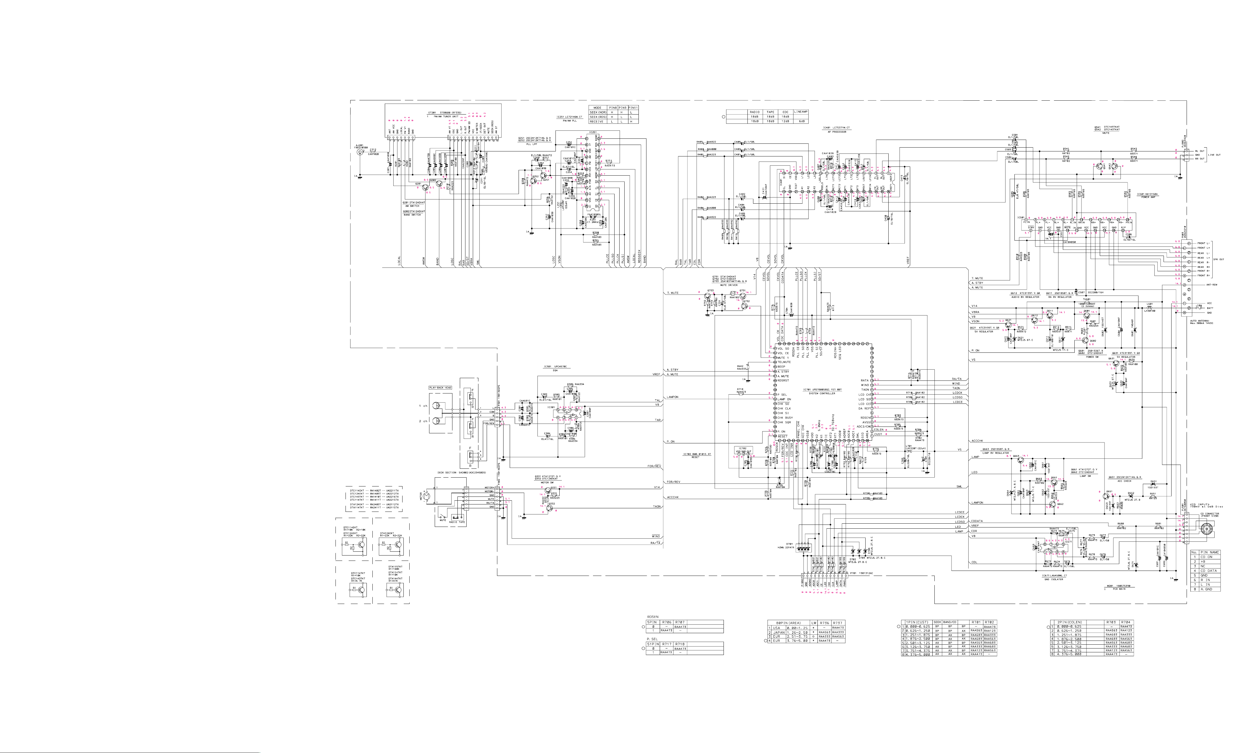
SCHEMATIC DIAGRAM - MAIN FOR FXC-750GD/A.SS
Gain Settings
A3 None
Shintom
REMARK
Without RDS
With RDS
REMARK
With Clock
Without Clock
Clock
CDC
With
With
With
With
Without
Without
Without
Without
Page 48

SCHEMATIC DIAGRAM - MAIN FOR FXC-755RDS/XE
GAIN settings
A3
Shintom
REMARK
without RDS
with RDS
REMARK
with Clock
without Clock
Clock
with CDC
with CDC
with CDC
with CDC
without CDC
without CDC
without CDC
without CDC
Page 49

SCHEMATIC DIAGRAM - DISP FOR FXR-725GD/SS, A.SS, XE
SCHEMATIC DIAGRAM - DISP FOR FXR-730GD/A.SS, FXC-750GD/A.SS SCHEMATIC DIAGRAM - DISP FOR FXR-755RDS/XE
Page 50

VT
CIRCUIT BOARD PARTS LOCATION - MAIN
CIRCUIT BOARD PARTS LOCATION - MAIN
FOR FXR-725GD/SS, A.SS, XE
FOR FXR-730GD/A.SS
AM VT
FM VT
VT
AM VT
FM VT
Page 51

CIRCUIT BOARD PARTS LOCATION - MAIN
AM VT
FM VT
AM VT
FM VT
CIRCUIT BOARD PARTS LOCATION - MAIN
FOR FXC-755RDS/XE
AM VT
FM VT
FOR FXC-750GD/A.SS
AM VT
FM VT
Page 52

CIRCUIT BOARD PARTS LOCATION - DISPLAY
CIRCUIT BOARD PARTS LOCATION - DISPLAY
FOR FXR-725GD/SS, A.SS, XE
FOR FXC-755RDS/XE
CIRCUIT BOARD PARTS LOCATION - DISPLAY
FOR FXR-730GD/A.SS, FXC-750GD/A.SS
Page 53

FXR-725GD
FXR-730GD
FXC-750GD
FXC-755RDS
No. 289A2870
Printed in Japan Issue date 05-01
Page 54

Notice
CORRECTION
SERVICE FLASH
CORRECTION
Please add this notice to the Service Manual listed below.
Category : Cassette Player Date : Feb. 2002
Model :
Destination : A.SS, SS, XE Reference No. : SM-7900005 Issue Number : 1
The reason of change.
A : Misprint B : Quality Reliabilities C : Standardization
D : Design E : F :
G :
Prod. Code : FXR-725GD (A.SS) FXR-725GD (SS) FXR-725GD (XE)
In the parts list for cassette deck mechanism, “–” (hyphen) of the part number is taken and a part number is made
into 12 figures.
FXR-725GD, FXR-730GD, FXC-750GD, FXC-755RDS
114782847 114782846 114782839
FXR-730GD (A.SS) FXC-750GD (A.SS) FXC-755RDS (XE)
114782842 114782843 114782840
PRODUCTION CHANGE
ADD INFORMATION
CORRECTION
FILE NO.
Page & Section Ref. No. Part No. Description Q‘ty Interchangeability Reason
Page & Section
CASSETTE DECK
MECHANISM
(PAGE 19, 20)
OLD TKXXXX-XXXXXX
NEW TKXXXXXXXXXX C
Feb. / ’02 Printed in Japan
SANYO Electric Co., Ltd
Osaka Japan
(1/4)
REFERENCE No. SM-7900005-01
Page 55

CASSETTE DECK MECHANISM EXPLODED VIEW
(MECHANISM #5AD002)
1
2
3
9
10
4
5
6
7
8
35
36
37
33
34
39
40
64
56
63
57
65
66
62
67
68
61
60
93
59
58
69
70
95
55
54
71
72
73
74
75
42
45
41
38
46
48
47
94
48
49
52
51
50
91
78
53
90
92
76
77
87
89
88
86
85
84
83
82
81
80
79
(2/4)
43
44
11
12
13
14
15
18
19
20
21
22
23
95
95
* When repairing any of the numerous precision parts in the cassette deck mechanism, a high degree of skill is necessory and
the cost of parts may not necessarily be cheaper than for the whole mechanism.
In addition, parts from the deck mechanism exploded view and parts list are only for technical reference. These parts may or
may not be individually available.
16
17
28
29
30
3255
24
25
26
27
31
Page 56

CASSETTE DECK MECHANISM (5AD002)
Ref. No. Part No. Description
1 TK6107000323 SPRING-F
2 TKMT7500047X ASS’Y CASE L/P
3 TK6003000305 SCREW (M2x4)
4 TK6107000369 SPRINF L/P
5 TK6107000339 SPRING E/P
6 TK6031000446 WASHER(1.6x3.5x0.25T)
7 TKMT7000439B CASE E/P
8 TKMT7200027A ARM-C
9 TKMT7000076A CASE CASSETTE
10 TKMT7000438T HOLDER-C
11 TKMT9011011A ASS’Y ARM PLAY
12 TK6031001032 WASHER (1x3.2x0.25T)
13 TKMT7200331N GEAR CLUTCH 1
14 TKMT7400091C FELT CLUTCH
15 TKMT7200331P GEAR CLUTCH 2
16 TK6107001021 SPRING CLUTCH
17 TKMT7200046A CLUTCH BODY
18 TK6031000575 WASHER (1.2x3.5x0.5T)
19 TKMT7200331M GEAR CAM
20 TK6031000425 WASHER (1.2x3x0.25T)
21 TKMT6600025A GEAR SENSOR
22 TK6031000425 WASHER (1.2x3x0.25T)
23 TKMT6600017A GEAR 19.6B
24 TK6031000433 WASHER (1.2x3.2x0.35T)
25 TKMT7200379D GEAR REEL
26 TKMT7200126A SENSOR PULLEY
27 TK6107000191 SPRING B/T
28 TK6031000623 WASHER (1.2x3x0.25T)
29 TKMT7200379C GEAR PLAY-B
30 TKMT7200331G ARM SENSOR
31 TKMT7500047K ASS’Y CHASSIS REEL
32 TK6003000305 SCREW (M2x4)
33 TKMT6100002A SPRING SWITCH
34 TKMT7000438Z LEVER SWITCH
35 TK6107001061 SPRING TRIGGER
36 TK6107000249 SPRING ARM LOCK
37 TKMT7200380G ARM LOCK
38 TK6009000333 SCREW ARM LOCK
39 TKMT7200104A PULLEY CENTER
40 TK6031000431 WASHER (1.2x3x0.25T)
41 TK6001001048 SCREW (M2x2.5)
42 TKMT7500059A ASS’Y -EJECT A C/K
43 TKMT9011010N ASS’Y MOTOR
44 TKMT7000438R LEVER EJECT-B
45 TK6107001023 SPRING EJECT-B
46 TK6107001022 SPRING EJECT-A
47 TKMT6600016A GEAR 18.6B
48 TKMT9101011K ASS’Y FLYWHEEL
49 TK6602000106 BELT (120.2)
50 TK6031001082 WASHER (2.1x5x0.5T)
51 TK6107001028 SPRING LEVER PLAY
52 TKMT7000438W LEVER PLAY
(3/4)
Page 57

CASSETTE DECK MECHANISM (5AD002)
Ref. No. Part No. Description
53 TKMT9002013J ASS’Y CHASSIS MAIN
54 TKMT9121013R ASS’Y PCB HEAD
55 TK6003000322 SCREW (2x3.7)
56 TK6031000464 WASHER (1.9x3.2x0.25T)
57 TK6044000272 E-RING (ø1.5)
58 TK6031000486 WASHER (2.1x4x0.4T)
59 TKMT7500058A ASS’Y ARM C/R
60 TKMT9015010E ASS’Y PINCH R
61 TKMT9015010D ASS’Y PINCH F
62 TKMT7000438P LEVER PRO
63 TK6031000486 WASHER (2.1x4x0.4T)
64 TK6107001026 SPRING LEVER PRO
65 TK6031000430 WASHER (1.2x3.2x0.35T)
66 TKMT7000438Y LEVER LOCK
67 TK6107001048 SPRING LEVER LOCK
68 TKMT7500047V ASS’Y BASE FR C/K
69 TK6031001082 WASHER (2.1x5x0.5T)
70 TKMT7200379E STOPPER LEVER
71 TK6003000305 SCREW (M2x4)
72 TK6107001054 SPRING FF/REW
73 TKMT7000487Q LEVER FF
74 TK6107001054 SPRING FF/REW
75 TKMT7000487R LEVER REWIND
76 TK6009000334 SCREW AZIMUTH
77 TK6003000295 SCREW (M2x5.5)
78 TK6107000366 SPRING PINCH
79 TK6107001049 SPRING BASE HEAD
80 TKMT9002013H ASS’Y BASE HEAD C/K
81 TKMT7200331K PLATE HEAD-B
82 TKMT7200056A HOLDER H/B
83 TKMT7200079A PLATE HEAD-A
84 TK6009000334 SCREW AZIMUTH
85 TKMT5900052A HEAD (TC860CPRF)
86 TK6107000345 SPRING AZIMUTH-R
87 TK6107000201 SPRING AZIMUTH-F
88 TK6002001011 SCREW (M2x3)
89 TKMT7000438A STOPPER AZIMUTH
90 TKMT6100007A SPRING EJECT
91 TKMT6000025A SCREW (Ml.7x2)
92 TKMT7000487U EJECT STOPPER
93 TKMT4100160B HEAD CONNETOR ASS’Y
94 TKMT4100160A MOTOR CONNECTOR ASS’Y
95 TKMT7100012A Nylon Tube (L-40mm)
(4/4)
 Loading...