

Page 1
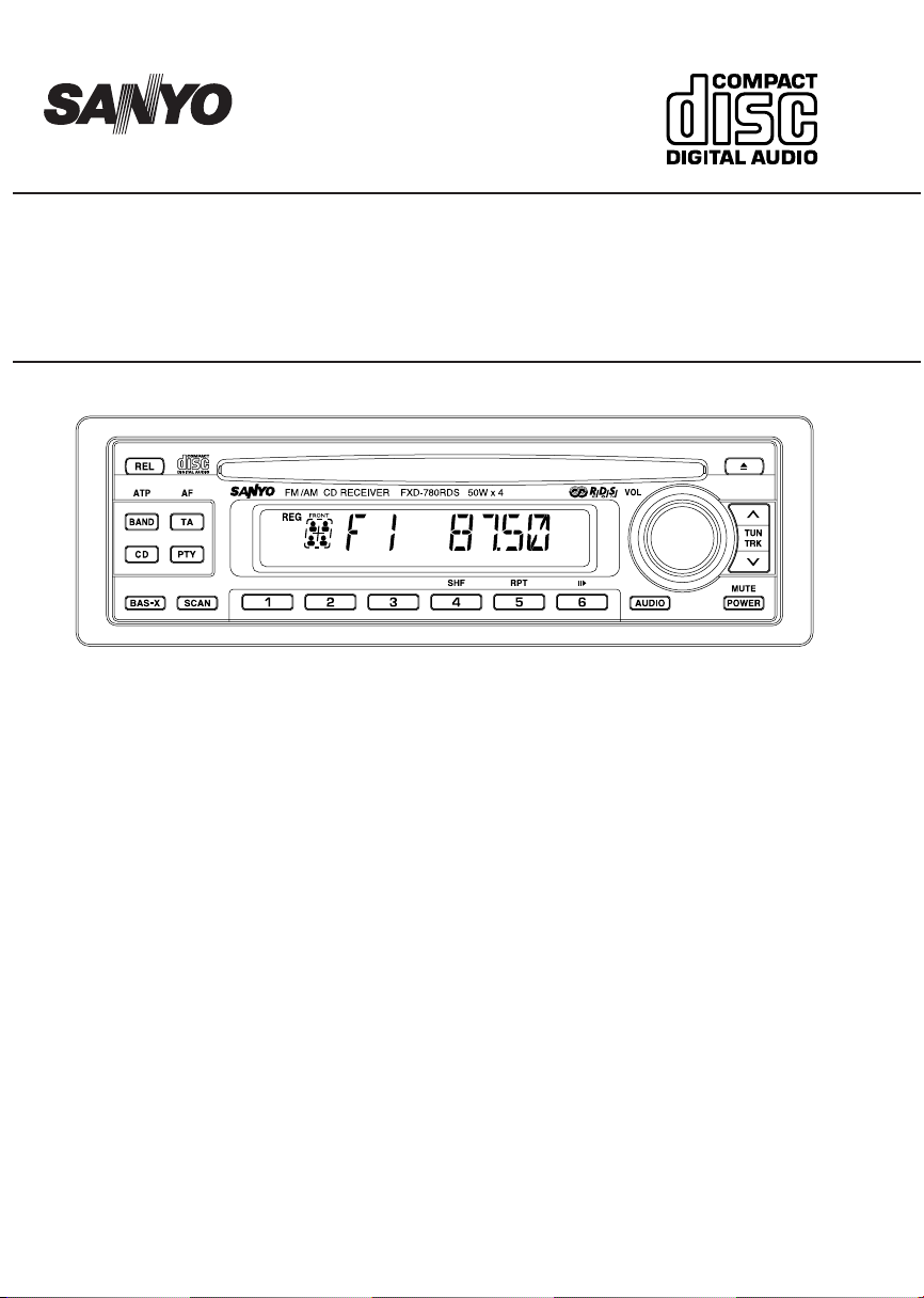
FXD-780RDS
CDC
+
- -
DISC -
Full Panel Detachable
High Power FM/AM Stereo Receiver
Compact Disc Player with CD Changer Controller
ISO Mounting with Removable Trim Ring
with CD Changer Control
OPERATING INSTRUCTIONS ..................... 1~24
Page 2

CONTENTS
COMPACT DISC CARE ........................................................................................................................... 2
DIGITAL DISPLAY .................................................................................................................................... 3
DETACHABLE FRONT PANEL ................................................................................................................ 4
GENERAL OPERATION .......................................................................................................................... 5
RADIO OPERATION ................................................................................................................................ 9
RDS OPERATION .................................................................................................................................. 11
CD OPERATION..................................................................................................................................... 14
CD CHANGER OPERATION ................................................................................................................. 16
ERROR SIGNS ...................................................................................................................................... 18
HINTS FOR PROPER AND SAFE OPERATION .................................................................................. 19
TROUBLESHOOTING ........................................................................................................................... 20
ACCESSORIES AND HARDWARE ....................................................................................................... 21
UNIT REMOVAL ..................................................................................................................................... 22
ELECTRICAL CONNECTIONS .............................................................................................................. 23
LINE OUT CONNECTIONS ................................................................................................................... 24
CAUTION
• This unit is designed to operate on 12 volts DC, NEGATIVE ground electrical systems only.
• When fuse replacement is necessary, use only a 10 amp fuse. Do not replace with a higher rated fuse. If
the fuse blows often, carefully check all electrical connections for any short circuits and have your car’s
voltage regulator checked also.
• Do not install the unit where it will be exposed to direct sunlight or hot air discharged from the car heater.
• Do not expose the unit to water or moisture.
• To avoid damaging the unit, never insert anything other than a compact disc into the disc slot.
• This unit should not be adjusted or repaired by anyone except qualified service personnel.
If servicing is required, return the unit to an authorized SANYO mobile audio dealer.
• Use the Controls or adjustments or performance of procedures other than those specified herein may
result in hazardous radiation exposure.
• Changes or modifications not expressly approved by SANYO may void the uses’s authority to operate
this equipment.
GB–1
Page 3
COMPACT DISC CARE
Dirt, dust, scratches and warpage can cause a deterioration in the sound or intermittent skipping some
tracks during play.
• This unit has been designed to play compact
discs bearing the identification logo shown
on the left. No other discs can be played.
• Do not use non-conventional discs such as
heart- shaped, octagonal discs, etc.
The player could be damaged.
• Fingerprints and dust should be carefully
wiped off the signal surface of the disc
(glossy side) with a soft cloth.
Wipe in a straight motion from the inside to
the outside of the disc. Unlike conventional
records, the compact disc has no grooves to
collect dust and debris. Small dust particles
will have no effect on reproduction quality.
• Do not insert a disc which is cracked into the
unit.
• Do not apply paper or write anything on the
surface of the disc.
• To prevent warping the disc, do not expose
it to direct sunlight, high humidity or high temperatures for extended periods of time.
• Never use chemicals such as record cleaning sprays, antistatic sprays or fluids, benzene or thinner to clean compact discs.
These chemicals will permanently damage
the plastic surface of the disc.
Benzene Thinner Cleaning spray
• When not using the disc player for extended
periods of time, remove the compact disc and
return it to the plastic storage case. This will
protect the disc from dust and exposure to
the sun.
Recommended CD-R Media
Data may not be properly written to CD-R media depending on the quality of the media. If this
happens, the data may not be reproduced correctly. We recommend the following manufacturers to insure proper quality of the media.
CD-R Media
TDK USA Corp., Taiyo Yuden (U.S.A.), Inc., Ricoh Corporation, Eastman Kodak Company,
Maxell Corporation of America, Mitsubishi Chemical Corporation, Fuji Photo Film U.S.A.,
Inc., Mitsui Chemicals, Inc., Sony Corporation of America, Philips Electronics North America
Corporation, Imation Corp.
Additionally, CD-R media compatible with various speeds such as 2X and 1X-4X are available. Please refer to the instruction manuals of the drive and the recording software you are
using to selection of the correct media.
GB–2
Page 4
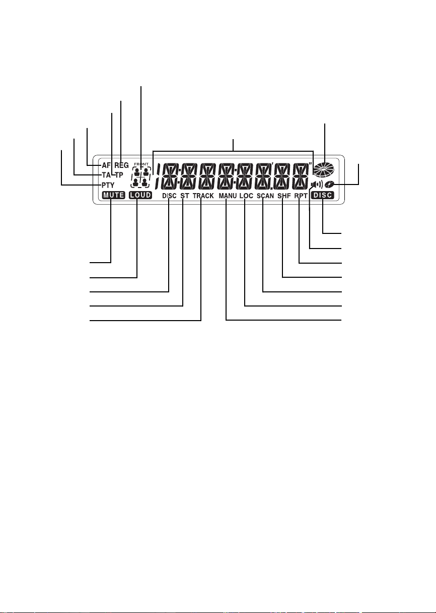
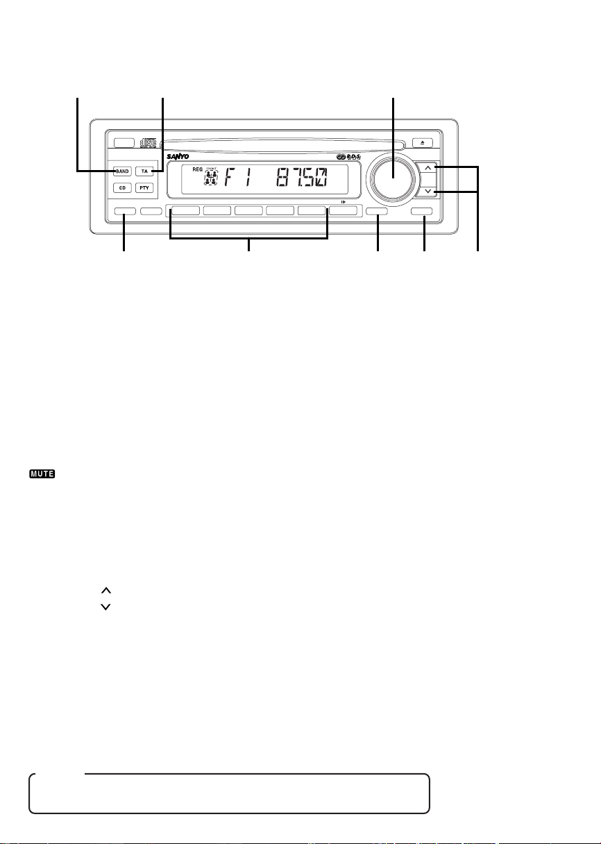
DIGITAL DISPLAY
Audio Position
REG
TP
AF
TA
PTY
Mute
Loudness
CD changer
mode
FM Stereo
Track No.
Radio Frequency, Time, CD
Track Number, Audio Control
Selected Mode
CD running indicator
Disc IN
CD changer mode
(Disc repeat/
shuffle/scan)
BAS-X
Repeat Play
Shuffle Play
Scan
Local/DX
Manual tuning
GB–3
Page 5
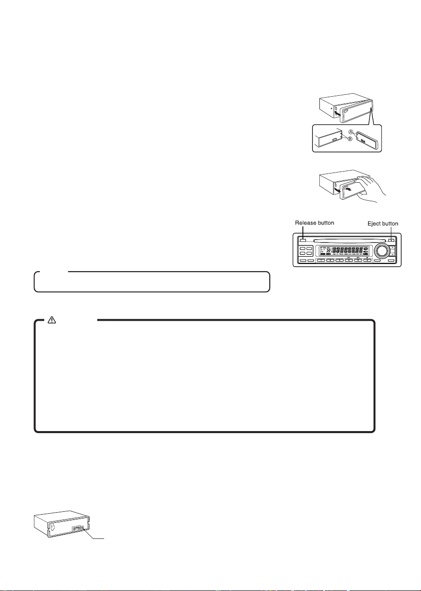
DETACHABLE FRONT PANEL
The front panel is designed to be removable for antitheft purposes.
It is recommended that you remove and carry the front panel with you when you leave your car.
HOW TO ATTACH THE FRONT PANEL
Align the right side of the panel with the stopper, and then push the left
side of the panel into the unit until it clicks.
HOW TO DETACH THE FRONT PANEL
Press the release button (REL) to release the front panel.
Pull the entire panel to remove it from the unit.
RETURNING TO THE INITIAL SETTINGS
When the eject button is pressed for more than 10 seconds, the microcomputer of the unit returns to the initial settings. If the display window
is not properly shown or the unit malfunctions, press the eject button for
more than 10 seconds.
Note
The unit will not operate if it is installed incorrectly.
CAUTION
• Do not attempt to remove the panel in a manner other than that described
above.
• When installing the panel, do not force it into the unit.
• Do not touch the connection terminals of the panel or the unit. It may cause
poor contact.
• Use a clean, dry cloth when cleaning the terminals.
• Keep the panel out of direct sunlight and high temperatures.
• Prevent the panel from coming into contact with benzene, thinner, or in-
secticides.
• Do not drop the panel.
SECURITY INDICATOR
When the front panel is detached, you can find an RED indicator on the front side of the unit. This indicator
designed to deter theft, and continues to flash.
This unit is not equipped with any other security systems such as a security alarm, so there are limitations
to its effectiveness.
Security system indicator
GB–4
Page 6
GENERAL OPERATION
256
REL
ATP
CDC
BAS-X
7
AFAF
SCAN
FM /AM CD RECEIVER FXD-780RDS 50W x 4
+
- -
DISC -
1
23456
4
RPTSHF
VOL
AUDIO
3
MUTE
POWER
1
TUN
TRK
8
TURNING THE POWER ON......................................1
Install the front panel and press the PWR MUTE button 1 when ACC is on.
TURNING THE POWER OFF ............................................................. 1
Press the PWR MUTE button for more than 2 seconds. Display will revert to clock indication.
VOLUME LEVEL CONTROL.......................................2
Rotate the VOL dial 2 to adjust the volume level.
MUTING THE SOUND .......................................................................... 1
Press the PWR MUTE button 1 while the receiver is on. While muting the sound, the MUTE indicator
on the display is blinking. To restore the previous volume level, press PWR MUTE button again.
SETTING THE CLOCK..................................3, 2, 6, 8
The clock uses a 24-hour display system.
1. Press the AUDIO button 3 for more than 2 seconds.
2. Press the following buttons to set the clock.
VOL dial 2 : Adjust the hour and minutes.
TUN/TRK 8 : To activate Hour blink.
TUN/TRK 8 : To activate Minute blink.
BAND ATP 6 : Adjust the minutes to zero.
3. Press the AUDIO button 3 to activate the clock.
CT(Clock Time) select....................................................................... 5
Press the TA AF button 5 while the clock indicator flashes in order to select or deselect the CT if so
desired. (The CT function is initially set to ON when shipped)
The CT function of the RDS enables the built-in clock in the unit to automatically synchronize with the CT
data. When you select “CT ON”, the clock is automatically adjusted to the local time transmitted by an RDS
station.
(Example) 12:29 → 12:00
12:30 → 13:00
Notes
• The CT function may not work even though an RDS station.
• The time set by the CT function may not be accurate.
GB–5
Page 7

SWITCHING THE DISPLAY ........................................3
Each time you press the AUDIO button 3, the item changes as follows ;
Initial set
↓
PS ➔ Frequency ➔ PTY ➔ Clock ➔ BAS ➔ TRE ➔ LOUD ➔ BAL ➔ FAD ➔ Mute level ➔ LO/DX
DISPLAY PRIORITY SELECTOR ...................................................... 3
You can adjust with which priority items are to be displayed. Display priority can be set for the following
four items ;
• PS (Programme Service name) • PTY (Programme Type)
• Frequency • Clock
Press the AUDIO button 3 until your requested item being displayed, then hold the AUDIO button 3 pressed
for more than 2 seconds (Beep tone will be heard) to set priority to the item.
ADJUSTING THE SOUND
CHARACTERISTICS .............................................2, 3
1. Each time you press the AUDIO button 3 until the desired mode is displayed.
2. Rotate the VOL dial 2 to adjust the selected item. Make the adjustment within 5 seconds after selecting.
After 5 seconds, the display window will revert to display priority.
• MUTE LEVEL controls the volume level used when the sound is muted. You can adjust the level by
the volume is reduced from the previous volume level.
Adjustment Range
BASS (BAS 0) BAS –5 BAS +5
TREBLE (TRE 0) TRE –5 TRE +5
LOUDNESS (LOUD OFF) LOUD ON LOUD OFF
BALANCE (L 0:R 0) BAL L9 R0 (Full left) BAL L0 R9 (Full right)
FADER (R 0:F 0) FAD R0 F9 (Full front) FAD R9 F0 (Full rear)
MUTE LEVEL (MUTE –20) MUTE – 0 MUTE –80
Local/DX(SENS DX) SENS DX SENS LO
LOUDNESS EFFECT
When listening to music at low volume levels, this feature will boost the extremes of the bass and treble
ranges to compensate for the negative characteristics of human hearing.
LOCAL/DISTANT(LO/DX) SELECTION
This feature is used to select the strength of the signals at which the radio will stop during Automatic
Tuning. Select the Local (LO) setting and only the strongest (local) stations will be received. The “LOC”
indicator appears in the display window.
Select the Distant setting and the radio will stop at a wider range of signals, including weaker more distant
stations. The “LOC” indicator will go out on the display window.
GB–6
Page 8
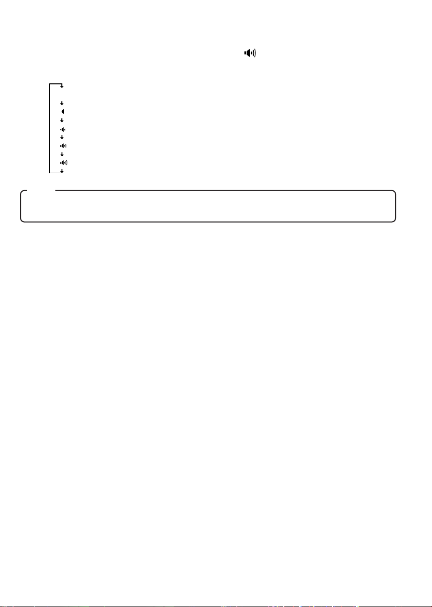
ENHANCING THE BASS SOUND (BAS-X)....................................... 7
Press the BAS-X button 7 to display the BAS-X INDICATOR ( ) on the display window.
Each time you press the BAS-X button 7, current mode appears on the display window and the mode
change as follows.
(No display)
BAS-X 0 (No BASS enhanced)
BAS-X 1 (Enhanced BASS level : LOW)
BAS-X 2 (Enhanced BASS level : Middle)
BAS-X 3 (Enhanced BASS level : High)
BAS-X 4 (Enhanced BASS level : Very high)
Note
Settings for BASS, TREBLE, LOUDNESS and BAS-X can be made to each of
the following modes independently: FM, AM, and CD.
GB–7
Page 9

ADJUSTING THE SOUND STAGE .............................4
You can adjust the position of sound stage to best serve a particular seat.
TO MEMORY THE SOUND STAGE ................................................... 4
1. Adjust the BALANCE & FADER.
2. Press the appropriate Preset buttons 4 for more than 2 seconds. The balance & fader indicator blinks
and adjusted sound stage is stored.
TO CALL THE SOUND STAGE ......................................................... 4
Press the appropriate Preset buttons 4 to call the desired sound stage during the BALANCE & FADER
adjustment mode. The Preset buttons are factory-set to the following conditions.
BALANCE FADER
1
P 1
P 2
P 3
P 4
P 5
Each time you press the Preset buttons 4 in the BALANCE & FADER adjustment mode, the audio position
indicator changes as follows ;
: For the left seat ( L0 R2 ) ( R4 F0 )
2
: For the front seat ( L0 R0 ) ( R4 F0 )
3
: For the right seat ( L2 R0 ) ( R4 F0 )
4/SHF
: For the rear seat ( L0 R0 ) ( R0 F4 )
5/RPT
: For all the seat ( L0 R0 ) ( R0 F0 )
1
2 3
4/SHF
5/RPT
TEL MUTE FUNCTION
Shut down the audio system temporarily whenever an incoming call is received.
When the telephone rings:
When a call is received, “TEL–MUTE” is displayed and all the unit functions are temporarily interrupted.
Turning TEL Mute Function Off After Phone Call:
Hang the phone up.
“TEL–MUTE” disappears from the display window. The original source (i.e., the one used before the phone
call) is returned to automatically, and the volume restored.
Note
The function will not work if a cable is not connected to the car phone.
IGNITION-OFF CLOCK RECALL .............................3
Press the AUDIO button 3 while the ignition switch is in the “OFF” position.
The display will illuminate showing the time and then automatically shut off after 5 seconds.
GB–8
Page 10

RADIO OPERATION
1
REL
ATP
CDC
BAS-X
AFAF
4
SCAN
FM /AM CD RECEIVER FXD-780RDS 50W x 4
+
- -
DISC -
1
23456
RPTSHF
VOL
AUDIO
MUTE
POWER
TUN
TRK
23
SELECTING RADIO MODE
Press the BAND ATP button 1 to switch from CD mode to the radio mode.
Each time the BAND ATP button is pressed, the selected band changes as shown below.
FM 1(F 1) ➔ FM 2(F 2) ➔ FM 3(F 3) ➔ AM 1(A 1) ➔ AM 2(A 2)
RADIO TUNING .................................................................................. 2
• Automatic tuning ............. Press the TUN/TRK or Button 2.
• Manual tuning ................. To select higher frequency station, press the TUN/TRK button for more than
When the button is pressed, the system will start automatic tuning and stop at
the next receivable station.
0.5 seconds. The “MANU” indicator appears in the display window. To select
lower frequency stations, press the TUN/TRK button for more than 0.5 seconds. To quickly scan up or down in frequency, press and hold the TUN/TRK
or button. Release the button when the display approaches the desired
frequency, then press and release the button repeatedly until the desired frequency is displayed. After 4 seconds of completing Manual Tuning, the tuning
control will revert to the Automatic Tuning mode.
STORING PRESET STATIONS .......................................................... 3
The preset buttons 3 can be used to store 6 stations in each band (FM 1, FM 2, FM 3 and AM 1, AM 2) for
convenient access to your favorite stations.
• Programming stations ..... 1. Select the desired band, then tune in the station you want to store in memory.
2. Press and hold one of the preset buttons 3 for more than 2 seconds until the
frequency indicator flashes twice. Repeat steps 1. and 2. to program additional stations.
• Quick tuning .................... Select the desired band, then press one of the 6 preset buttons 3.
GB–9
Page 11

ATP (AUTO TRAVEL PRESET) OPERATION ................................... 1
The Auto Travel Preset function searches for and memorizes the 6 strong stations in one of the two bands
(FM 3, AM 2) in order of signal strength.
This feature is useful when you are driving in an unfamiliar location and want to memorize local stations
without changing the standard preset stations.
A total of 12 stations (6 FM and 6 AM) can be programmed.
• To set the stations .................... Select the desired band. Press and hold the BAND ATP button 1 for
• Quick tuning of ATP stations..... Select the desired band, then press one of the 6 preset buttons 3.
more than 2 seconds.
Note
This function is available for FM 3 and AM 2.
SCAN OPERATION ............................................................................ 4
1. Press the BAND ATP button 1 to select the desired band.
2. Press the SCAN button 4. The system will select and receive each station for 10 seconds.
3. To stop scanning and retain the station currently selected, press the SCAN button 4 again.
PRESET SCAN OPERATION .............................................................. 4
This function scans each of the preset stations stored in the selected band (both manual preset and auto
travel presets).
1. Press the BAND ATP button 1 to select the desired band.
2. Press the SCAN button 4 for more than 2 seconds. The system will select and receive each preset
station for 10 seconds.
3. To stop scanning and retain the station currently selected, press the SCAN button 4 again.
GB–10
Page 12

RDS OPERATION
Radio Data System (RDS) is a digital information system that sends additional digital information along
with the regular FM radio programme signal. As soon as a radio station has been identified, the station
name, including a regional identifier if applicable, will appear in the display window, for example SWF4MZ
(local radio station of Rhein hassen, Germany). This is also one of the RDS functions. Your car stereo
offers you more convenience when receiving FM stations with RDS.
3
1
CDC
+
- -
DISC -
24
6
5
CHANGING THE DISPLAYED ITEMS
SELECTING AF MODE ...................................................................... 1
Hold the TA AF button 1 for more than 2 seconds to display “AF” indicator in the display window. Press
again for more than 2 seconds to cancel this feature.
AF : The unit will automatically tune to a frequency offering better reception of the same RDS programme.
Seek tuning in the AF mode causes the unit to receive RDS stations only, with “RDS SEEK” appearing in the display window.
SELECTING TA MODE ...................................................................... 1
Press the TA AF button 1 to display “TA” indicator in the display window. Press again to cancel this feature.
TA : The unit will only play stations offering traffic announcements.
Seek tuning in the TA mode causes the unit to receive traffic information only, with “TP SEEK”
appearing in the display window.
Notes
• In the AF mode, “NO ALTERNATIVE FREQUENCY AVAILABLE” appears in the
display window when the unit receives a weak signal and fails to find an alternative station.
• In the TA mode, the display window shows “NO TRAFFIC INFO AVAILABLE”
when the unit does not receive any traffic information.
• In the AF mode, “PI SEEK” appears on the display window when the unit fails to
find any RDS stations after you press the preset button for predefined RDS stations. In this case, the unit will automatically seek the same programme corresponding to a preset station.
GB–11
Page 13

AUTOMATIC RE-TUNING ...................................1,3,5
The Alternative Frequencies (AF) function automatically selects and tune to the station with the strongest
signal in a network. By using this function, you can continuously listen to the same programme during a
long-distance drive without having to re-tune the station manually.
1. Press the BAND ATP button 3 to select the FM band.
2. Hold the TA AF button 1 for more than 2 seconds to display the “AF” indicator in the display window.
3. Press the TUN/TRK or buttons 5 to tune in to a desired RDS station includes the AF data, the units
starts searching for an alternative station with a stronger signal in the same network.
SELECTING REG ON OR REG OFF ................................................. 2
Hold the PTY button 2 for more than 2 seconds to select REG OFF. The “REG” indicator will go out in the
display window.
Hold the PTY button 2 again for more than 2 seconds to select REG ON. (There may be cases where this
function may not be activated in some areas, especially in the United Kingdom)
REG ON : The tuner remains tuned to the current regional programmes.
REG OFF : The tuner may tune to another regional programme in the network.
RECEIVING TRAFFIC ANNOUNCEMENTS...............1,3
The Traffic Announcement (TA) and Traffic Programme (TP) data allows the radio to automatically tune in
to an FM station which broadcasts traffic announcements while you are listening to other programme
sources.
1. Press the BAND ATP button 3 to select the FM band.
2. Press the TA AF button 1 to display the “TA” indicator in the display window. Press the TA AF button
again to cancel.
You can listen to traffic announcements by using the Automatic or Manual tuning. “TP” appears in the
display window when the unit receives an RDS station broadcasting traffic announcements.
During reception of a traffic announcement, the “TA” indicator flashes in the display window. Then press
the TA AF button 1 to cancel Traffic announcement (but still in TA mode). To cancel the TA mode, press
the TA AF button 1 again during NO-reception of a traffic announcement.
PRESETTING THE VOLUME OF TRAFFIC ANNOUNCEMENTS .... 6
You can preset the volume level of the traffic announcements.
When a traffic announcement starts, the volume will be automatically adjusted to the preset level.
Rotate the VOL dial 6 to adjust to the desired volume level during reception of the traffic announcements.
GB–12
Page 14

LOCATING A STATION WITH PTY .............................2,4,5,6
You can locate the station you want to listen to by selecting one of the programmes from the following
table.
Programme types Display Programme types Display
News NEWS Weather WEATHER
Current Affairs AFFAIRS Finance FINANCE
Information INFO Children’s programme CHILDREN
Sport SPORT Social Affairs SOCIAL
Education EDUCATE Religion RELIGION
Drama DRAMA Phone In PHONE IN
Culture CULTURE Travel TRAVEL
Science SCIENCE Leisure LEISURE
Varied VARIED Jazz Music JAZZ
Pop music POP M Country Music COUNTRY
Rock music ROCK M National Music NATION M
Easy Listening Music EASY M Oldies Music OLDIES
Light classical LIGHT M Folk Music FOLK M
Serious classical CLASSICS Documentary DOCUMENT
Other music OTHER M
1. Press the PTY button 2 to display the last selected PTY by user.
2. Select your requested PTY in the PTY table using the VOL dial 6. PTY memorized in the Preset button
(1 - 6) 4 can be called directly.
The Preset buttons are factory-set to the following type of programmes.
P 1 : POP–M P 2 : ROCK–M P 3 : CLASSICS
P 4 : JAZZ P 5 : VARIED P 6 : NEWS
Then press the TUN/TRK and buttons 5 to search the PTY you want to listen.
3. In case the PTY you want to listen can not be found, it is back to the station received before PTY
searched, and display, for instance “NO” and “SPORT” mutually on the display window in case your
requested PTY is Sport.
4. In order to memorize PTY in the Preset, select PTY you want to memorize with VOL dial 6 then hold the
Preset button (1 - 6) 4 pressed for 2 seconds.
Notes
• The RDS function may not work properly in the area where the signal strength is
weak.
• Depending on the country or region, not all of the RDS functions are available.
GB–13
Page 15

CD OPERATION
The compact disc player will accept 5” CD only.
1
REL
ATP
AFAF
CDC
BAS-X
SCAN
3
FM /AM CD RECEIVER FXD-780RDS 50W x 4
+
- -
DISC -
1
23456
78
RPTSHF
6
VOL
AUDIO
5
2
MUTE
POWER
TUN
TRK
4
LOADING AND EJECTING THE CD
Insert a disc into the CD slot 1 and the CD player will start.
The system remains in CD mode and “ ” appears in the display window.
Press the eject button 2 to eject a disc.
SWITCHING TO CD MODE................................................................ 3
Press the CD button 3 with the power on to switch from radio mode to CD mode.
When the CD mode is switched on while a disc is loaded, play resumes from the point at which play was
stopped.
When the entire disc has played, the unit returns to the first track and play resumes.
The CD player continues playing the disc until the BAND ATP button is pressed, or the disc is ejected.
SKIPPING TRACKS ........................................................................... 4
Press the TUN/TRK button 4 to skip to the beginning of the next track.
Press the TUN/TRK button 4 to skip to the beginning of the track currently playing.
Press the TUN/TRK button 4 twice to skip to the beginning of the previous track.
Press and hold the TUN/TRK or button 4 for more than 0.5 seconds to search quickly (with sound) in
the forward or reverse direction.
When the button is released, the CD resumes normal play.
Notes
• Some CD-Rs (depending on the equipment used for its recording or the condition of the disc) may not play on this unit.
• You cannot play CD-R that is not finalized. (A finalize process necessary for
a recorded CD-R disc to be played on the audio CD player.)
• You cannot play CD-RWs (rewritable CDs) on this unit.
GB–14
Page 16

PLACING THE CD IN PAUSE MODE ................................................ 5
While playing a CD, press the Preset 6 button 5.
To resume playing, press the Preset 6 button again.
Notes
• During playback of a CD, the CD running indicator spins.
• The unit will turn-on automatically when a CD is inserted if the ignition switch
is “ON”.
REPEAT MODE .................................................................................. 6
Press the Preset 5 (RPT) button 6 to play the current track repeatedly.
The “RPT” indicator appears in the display window.
To cancel this mode, press the Preset 5 (RPT) button 6 again.
SHUFFLE MODE ................................................................................ 7
This function plays the tracks on a CD in random order.
Press the Preset 4 (SHF) button 7 to begin shuffle play.
The “SHF” indicator appears in the display window.
Press the button 4 to select another random track.
To cancel this mode, press the Preset 4 (SHF) button 7 again.
SCAN MODE (PLAYING THE BEGINNING
OF EACH TRACK) ............................................................................. 8
This function plays the first 10 seconds of each track sequentially.
Press the SCAN button 8 to begin the scan mode.
The “SCAN” indicator appears in the display window.
To cancel this mode, press the SCAN button 8 again.
GB–15
Page 17

CD CHANGER OPERATION
The unit can be used tocontrol the functions of the CD Changer. Please check with your nearest dealer for
recommendations of the models that will work with this unit.
REL
ATP
AFAF
CDC
BAS-X
SCAN
1
8
FM /AM CD RECEIVER FXD-780RDS 50W x 4
+
- -
DISC -
1
23456
7
RPTSHF
6
VOL
TUN
TRK
AUDIO
2
MUTE
POWER
534
SELECTING CD CHANGER MODE .........................1
Press the CD button 1 until the Disc No, Track No, and Track time appears on the display panel.
Press the CD button 1 again to change back to radio or CD operation.
PUTTING THE CD IN PAUSE MODE ................................................ 2
While playing a CD, press the Pause button 2 to place the changer in the pause mode.
To resume playing, press the Pause button 2 again.
SELECTING A DISC ........................................................................ 3,4
Press the DISC + button 3 to select the next disc.
Press the DISC – button 4 to select the preceding disc.
SKIPPING TRACKS ........................................................................... 5
Press the TUN/TRK button to skip to the beginning of the next track.
Press the TUN/TRK button to skip to the beginning of the track currently playing.
Press the TUN/TRK button twice to skip to the beginning of the previous track.
Press and hold the TUN/TRK button or for more than 0.5 seconds to search quickly (with sound) in
the forward or reverse direction. When the button is released, the CD resumes normal play.
GB–16
Page 18

REPEAT MODE .................................................................................. 6
• Repeat tracks ; ................ Press the RPT button 6 to play the current track repeatedly. “RPT” indicator
• Repeat discs ; ................. Press the RPT button 6 for more than 2 seconds to play the current disc re-
To cancel the track repeat or disc repeat mode, press the RPT button 6 again.
The system will remain in this mode until it is cancelled.
appears in the display window.
peatedly. “RPT” and “ ” appears in the display window.
SHUFFLE MODE ................................................................................ 7
This function plays the tracks on one CD or all CDs in the magazine in random order.
•“Shuffle-playing” tracks ; ....... Press the SHF button 7 to play the current disc in random order. “SHF”
•“Shuffle-playing” discs ; ........ Press the SHF button 7 for more than 2 seconds. “SHF” and “ ” ap-
To cancel the track shuffle or disc shuffle mode, press the SHF button 7 again.
The system will remain in this mode until it is cancelled.
indicator appears in the display window.
pears in the display window. The system selects a disc at random and
plays all tracks on that disc. When all tracks have been played, the next
disc is selected and “Shuffle-play” is repeated.
SCAN MODE
(PLAYING THE BEGINNING OF TRACKS OR DISCS) .................... 8
This function plays the first 10 seconds of each track or disc sequentially.
• Playing the beginning of tracks(Track Scan) ; ..... Press the SCAN button 8 to play the first 10 seconds
• Playing the beginning of discs(Disc Scan) ;......... Press the SCAN button 8 for more than 2 seconds to
To cancel the track scan or disc scan mode, press SCAN button 8 again.
of each track on the current disc in order. “SCAN” indicator appears in the display window.
play the first 10 seconds of each disc in the magazine.
“SCAN” and “ ” appears in the display window.
GB–17
Page 19

ERROR SIGNS
If a problem should occur while operating the CD player, one of the following error signs may be displayed.
Refer to the table below to identify the problem, then take the suggested corrective action. If the error
persists, contact your nearest dealer.
Message Cause Remedy
Dirty disc. Clean the disc.
Scratched disc. Replace the disc.
Up-side-down. Check the disc.
Focus error. Try ejecting and re-inserting
CD ERROR
MECK ERR.
Data and focus error. Under normal temperature
Mechanical problem. Eject and re-insert.
under normal temperature
conditions.
conditions, eject and insert
clean, undamaged disc
properly.
ERROR SIGNS (CD changer)
If a problem should occur while operating the CD changer, one of the following error signs may be displayed. Refer to the table below to identify the problem, then take the suggested corrective action. If the
error persists or “MECA ERR” and “09 ERROR” appears, contact your nearest dealer.
Message Cause Remedy
NO MAGA
NO DISC
CD ERROR
COMM ERR
TEMP ERR
No magazine.
No disc.
Up-side-down.
Communication error
Excessive temperature
conditions at the CD
changer.
Load the magazine in
the CD changer.
Check the disc.
Check the disc.
Check the connection of
the CD changer.
The error sign will go off
and play will resume
when the temperature at
the CD changer returns
to a normal range.
GB–18
Page 20

HINTS FOR PROPER AND SAFE OPERATION
• Condensation
Moisture can condense on the optical lens of the CD player during humid or rainy days, or after the car
heater is turned on. If this occurs the disc player may not function properly. To remedy the situation,
remove the disc from the unit and wait approximately one hour. This should allow the moisture to evaporate and restore normal operation.
• Temperature Consideration
The unit may not operate correctly in extremely hot or cold temperatures. Avoid exposing the unit to
extremely high or low temperatures.
• Interruptions in the sound (skipping)
When the car is driven on very rough surfaces, the sound from the CD player may skip and be interrupted. This will not cause any damage to the disc or the player. If this occurs, wait for the road surface
to improve before using the CD player.
• Safety
For safer driving, keep the volume at a moderate level to enable you to hear outside sounds (such as
emergency vehicle sirens).
• Cleaning the unit
Clean the unit with a soft, dry cloth. Stains should be removed by wiping the surfaces with a soft cloth
immersed in lukewarm water and wrung dry. Never use strong chemicals or solvents. These will damage
the finish of the unit.
• Disc care
When not using the disc player for extended periods, remove the compact disc and return it to the plastic
storage case. Do not leave a disc partially ejected from the player. If an ejected disc remains in the
loading slot for approximately 10 seconds, the player will reload the disc to prevent damage.
• Servicing
Should a problem develop, do not open the unit or try to repair it yourself. If servicing is required, bring
the unit to a Sanyo Authorized Service Center.
GB–19
Page 21

TROUBLESHOOTING
Sometimes a simple operational error or a mistake in the wiring can appear to be a problem with the unit.
Before having the unit serviced, refer to the troubleshooting chart below.
Symptom Cause Solution
The compact disc does not
play when inserted into the
unit.
No power.
The unit does not work properly (Eject, Load, Play)
The sound from the CD player
skips.
No radio reception.
The radio does not stop on
any stations when automatic
tuning is used.
The volume control is turned
down.
The power connections are
not wired correctly.
The vehicle ignition is
switched off.
The fuse is blown.
The microcomputer has been
affected by electrical noise.
The road surface is rough.
The unit is not mounted securely.
The disc is defective.
The disc is dirty.
The antenna cable is not connected.
The signal are weak.
Turn up the volume control.
Check the +12V and ground
connections.
Switch the ignition to the “ON”
or “ACC” position.
Replace the fuse with another
10A fuse.
Eject the disc, then insert it
again.
Wait for the road surface to improve before playing a disc.
Install the unit securely. Be sure
to use the rear strap if the vehicle does not provide support for
the rear of the unit. (See page
22)
Try another disc.
If it plays properly, the first disc
may be defective.
Clean the disc as explained on
page 2.
Insert the antenna cable firmly
into the antenna jack on the
unit.
Select a station using manual
tuning.
GB–20
Page 22

ACCESSORIES AND HARDWARE
INSTALLATION
Mounting Bracket Mounting Strap Locking Screw
(Half Sleeve)× 1 and Screws × 1 × 1
Removable Trim Ring Unlock Levers
× 1 × 2
INSTALLATION
1. BEFORE INSTALLATION
When mounting the unit in a car, keep the unit as level as possible.
If the unit must be mounted at an angle, due to the design of the vehicle, make sure the unit does not tilt by
more than 30°.
max. 30°
GB–21
Page 23

2. INSTALLATION PROCEDURES
FIRE WALL
DASH BOARD
OR CONSOLE
When mounting the unit into a DIN–standard cutout (182 × 53 mm) in the dashboard or console, attach the
provided Removable Trim Ring to the unit.
Mounting Strap
Mounting
Bracket
Removable
Trim Ring
1. Insert the mounting bracket into the DIN-standard cutout (182 × 53 mm) in the dashboard or console.
2. Bend the mounting bracket stopper outward until the bracket fits snugly in the cutout.
3. Attaching the Mounting Strap to the underside of the dash board, using screw. Attach the back of the
unit to the Mounting Strap using support stem bolt and hardware.
UNIT REMOVAL
1. Insert the unlock levers into the slots on each side of the unit until they click into place.
2. Pull the levers to remove the unit.
Notes
• Handle the unlock levers carefully to avoid injuring your fingers.
• Keep the unlock levers in a safe place for future use.
GB–22
Page 24

ELECTRICAL CONNECTIONS
WIRING
ANTENNA SOCKET
ANTENNA PLUG
(White)
(White/Black)
(Gray)
(Gray/Black)
(Green)
(Green/Black)
(Violet)
(Violet/Black)
+12V Constant Power Supply (Yellow)
+12V Accessory/Switched (Red)
Ground Wire (Black)
Power Antenna/Amplifier Turn On (Blue)
Tel mute (Brown)
CAUTION
• DO NOT connect any speaker wires to the metal body or chassis of the
vehicle.
• DO NOT connect the speaker common (–) wires to each other.
• Connect each speaker wire directly to each speaker terminal.
• All speaker common (–) wires must remain floating.
In the case of a 2-speaker system,
tape the ends of unconnected
terminals to prevent short circuit
2-speaker System4-speaker System
Front Left
Speaker
Front Right
Speaker
Rear Left
Speaker
Rear Right
Speaker
(White)
(White/Black)
(Gray)
(Gray/Black)
(Green)
(Green/Black)
(Violet
(Violet/Black)
Left
Speaker
Right
Speaker
Do Not
Connect
Do Not
Connect
1 Antenna socket
• Insert the plug from the antenna installed in your vehicle into this socket. (If your vehicle has a dual
antenna system, a dual antenna to single antenna cable adaptor may be required.)
2 + 12V Constant Power Supply (Yellow)
• Connect this wire to the +12V power terminal which receives power continuously.
3 +12V Accessory/Switched (Red)
• Connect this wire to the terminal which receives power while the ignition switch is ON or in the ACCESSORY position.
4 Ground wire (Black)
• Connect this wire to the vehicle chassis.
5 Power Antenna/Amplifier Turn On (Blue)
• Connect this wire to the control terminal of a Power Antenna or an external amplifier.
• When not using a Power Antenna or an external amplifier, this wire is not connected.
6 Tel mute (Brown)
• Connect to the terminal that is grounded when either the telephone rings or during conversation.
GB–23
Page 25

Notes
• When using a two-speaker installation, the Green, Green/Black, Violet, Violet/Black wires, which are used for a four-speaker installation, are not used.
The ends of these wires must be covered with electrical tape to prevent them
from shorting to the unit or the vehicle chassis.
• When using a two-speaker installation, set the FADER control to the center
position.
REPLACING THE FUSE
When fuse replacement is necessary remove the blown fuse
by using pliers. Then install the new 10 amp. fuse.
LINE OUT CONNECTIONS
• The unit has a built-in CD changer controller and line out terminals. You can use a compatible Sanyo CD
changer and a separate rear channel amplifier to upgrade your system.
RCA Line-out Jacks
White (Left)
Red (Right)
External Amplifier
CD Changer DIN Socket
CD Changer DIN Socket
• Connect the 8-pin DIN cable, which is supplied with the compatible Sanyo CD changer, to the DIN socket
on the back of the unit.
RCA Line- out Jacks (For Rear Speakers)
• Connect a patch cable (not supplied) from the White (left rear channel) and Red (right rear channel) RCA
line output jacks to the line input terminals of the external amplifier.
CD Changer
Rear Speaker
GB–24
Page 26

SANYO Electric Co., Ltd.
Printed in Singapore
Issue date 08-02
288F0630
 Loading...