

Page 1
FILE NO.
SERVICE MANUAL
REL
ATP
BAS-X
LO/DX
LOUD
FM/AM CD RECEIVER FXD-780GD 50W x 4
1
23456
RPTSHF
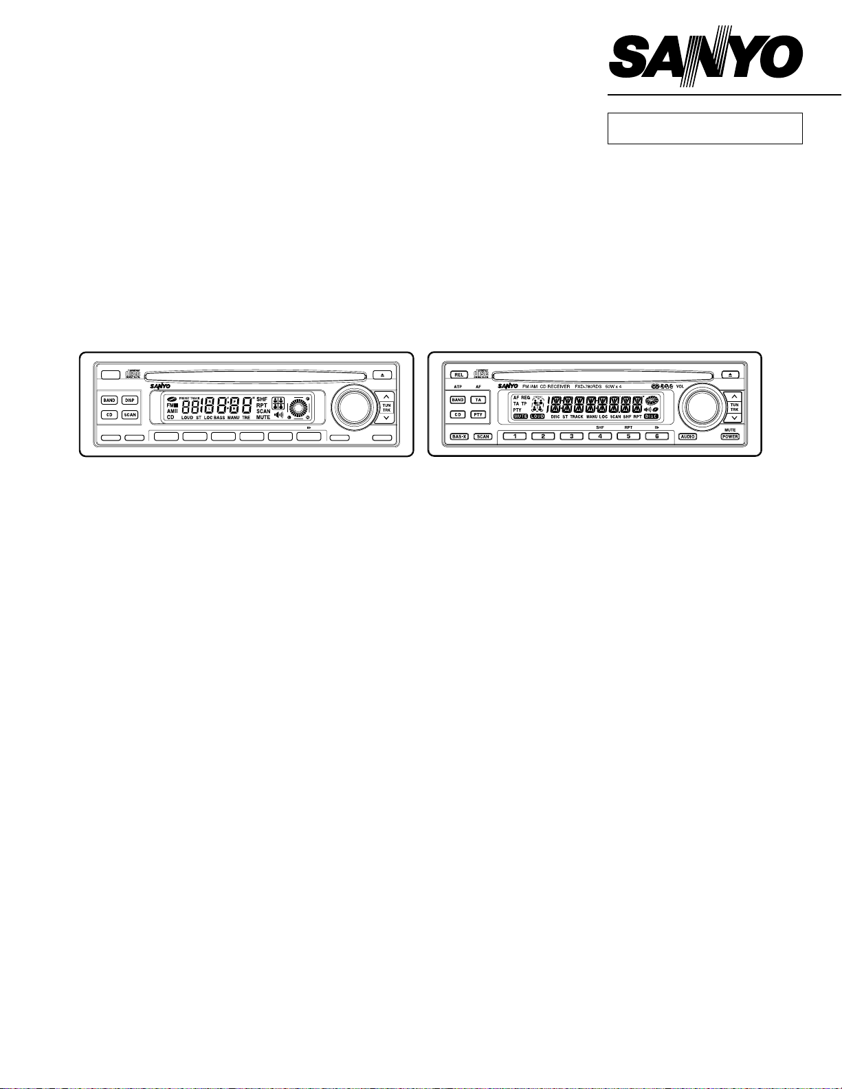
Full Panel Detachable
High Power
FM/AM Stereo Receiver
Compact Disc Player
VOL
TUNTUN
TRKTRK
AUDIO
MUTE
POWER
FXD-780GD
FXD-780GD (SS)
114782850
FXD-780GD (BK.SS)
114782855
FXD-780RDS (XE)
114782851
FXD-780RDS
Contents
SERVICE NOTES and PRECAUTIONS .................................................................................................................. 1
ELECTRICAL ADJUSTMENTS................................................................................................................................ 4
BLOCK DIAGRAM ..................................................................................................................................................11
IC/TRANSISTOR LEAD IDENTIFICATION............................................................................................................ 13
CD MECHANISM EXPLODED VIEW .................................................................................................................... 15
CABINET & CHASSIS EXPLODED VIEW............................................................................................................. 16
PARTS LIST - CABINET, CHASSIS AND ACCESSORIES ...................................................................................17
PARTS LIST - CD MECHANISM ........................................................................................................................... 19
PARTS LIST-MAIN................................................................................................................................................. 21
PARTS LIST-DISP ................................................................................................................................................. 30
PARTS LIST-RF33 ................................................................................................................................................. 32
SCHEMATIC DIAGRAM ........................................................................................................................................ 38
CIRCUIT BOARD DIAGRAM ................................................................................................................................. 44
REFERENCE No. SM-7900010
Page 2

Specifications
FM TUNER
Tuning Range.............................................................................. 87.5 - 107.9 MHz. (200 KHz. step)
87.5 - 108.0 MHz. (50 KHz. step)
Sensitivity .................................................................................... 1.5 µV
Separation................................................................................... 30 dB
Signal-to-Noise Ratio .................................................................. 65 dB (stereo), 70 dB (mono)
AM TUNER
Tuning Range.............................................................................. 530 - 1,710 KHz. (10 KHz. step)
531 - 1,602 KHz. (9 KHz. step)
Sensitivity .................................................................................... 20 µV
Signal-to-Noise Ratio .................................................................. 45 dB
CD PLAYER
Frequency Response .................................................................. 20 - 20,000 Hz.
Signal-to-Noise Ratio .................................................................. 90 dB
Channel Separation .................................................................... 60 dB
Dynamic Range .......................................................................... 90 dB
Harmonic Distortion..................................................................... 0.2 %
AUDIO AMPLIFIER & GENERAL
Maximum Output Power ............................................................. 50 W x 4 channels
Output Wiring .............................................................................. Floating-Ground type designed for
4-speaker use
RCA low-level outputs: 2 channels
Output Impedance ...................................................................... 4 - 8 ohms
Power Supply .............................................................................. 12 volts DC, negative ground
Specifications are subject to change without notice.
Page 3

SERVICE NOTES AND PRECAUTIONS
SERVICE NOTES
1. Make sure that the power lead is connected properly to
power source, otherwise damage to radio may result. If a
battery eliminator is used as a power source in place of a
battery, it must be filtered and regulated. (The power supply capacity should be more than 5 amps.)
2. Integrated circuits (ICs) are used in this unit. Because the
ICs are direc-coupled devices, as to all electronic equipment, reading within 10% of the indicated values are acceptable. Allowance must also be made for variations in
supply voltage. It is expected that any breakdown within
the IC results in drastic changes of the operating voltages
at the terminals.
3. When replacing a power output IC, remember to use the
IC specified in the parts list; Coat the IC-fin with silicon
grease.
WARNING
ln using meters, signal generator and any tool in servicing
Ics, extreme care is needed. DO NOT SHORT THE IC TERMINALS TO THE PATTERN ON THE PC BOARD OR TO
EACH OTHER. THE IC WILL BE INSTANTANEOUSLY DESTROYED.
ALIGNMENT PROCEDURE
Alignment is performed at factory with laboratory equipment.
Therefore, before alignment is attempted, the unit should be
thoroughly checked for circuit troubles.
NOTES:
1. Check for specified source voltage-DC, 14.4volts.
2. Connect an AC voltmeter (AC VM) across speaker or
dummy load (4 ohms. 20W , wirewound resistor)...see Fig.
11-3. (ELECTRICAL ADJUSTMENTS)
3. Signal input must be kept as low as possible to avoid overload and clipping (use highest sensitivity of output indicator).
4. Repeat adjustment to ensure good results.
5. Non-metallic alignment tools must be used (especially at
FM alignment).
6. For alignment location details, refer to CIRCUIT BOARD
DIAGRAM.
INSTALLATION PROCEDURE
1. To prevent a short circuit, remove the key from the ignition and disconnect the
2. Make the proper input and output wire connections for
each unit.
3. Connect the wiring harness wires in the following order:
ground, speakers, battery, ignition.
4. Connect the wiring harness connector to the unit.
5. Install the unit in your car.
6. Reconnect the
7. Disinstall by reversing the installation procedure.
battery.
battery.
CAUTION
• The rear-panel which also heatsink is very hot. Don’t burn!!
• If your car’s ignition does not have an ACC position, connect the ignition wires to a power source that can be turned
on and off with the ignition key . If you connect the ignition
wire to a power source with a constant voltage supply, as
with battery wires, the battery may die.
• If the console has a lid, make sure to install the unit so
that the cover will not hit the lid when closing and opening.
• If the fuse blows, first make sure the wires aren’t touching
to cause a short circuit, then replace the old fuse with one
with the same rating.
• Do not let unconnected wires or terminals touch metal on
the car or anything else conducting electricity. To prevent
a short circuit, do not remove the caps on the ends of the
unconnected wires or the terminals.
• Connect the speaker wires correctly to the terminals to
which they correspond. The unit may be damaged or fail
to work if you share the
metal part in the car.
• After the unit is installed, check whether the brake lamps,
blinkers, wipers, etc. on the car are working properly.
• Insulate unconnected wires with vinyl tape or other similar material .
wires or ground them to any
— 1 —
Page 4
SERVICE NOTES AND PRECAUTIONS
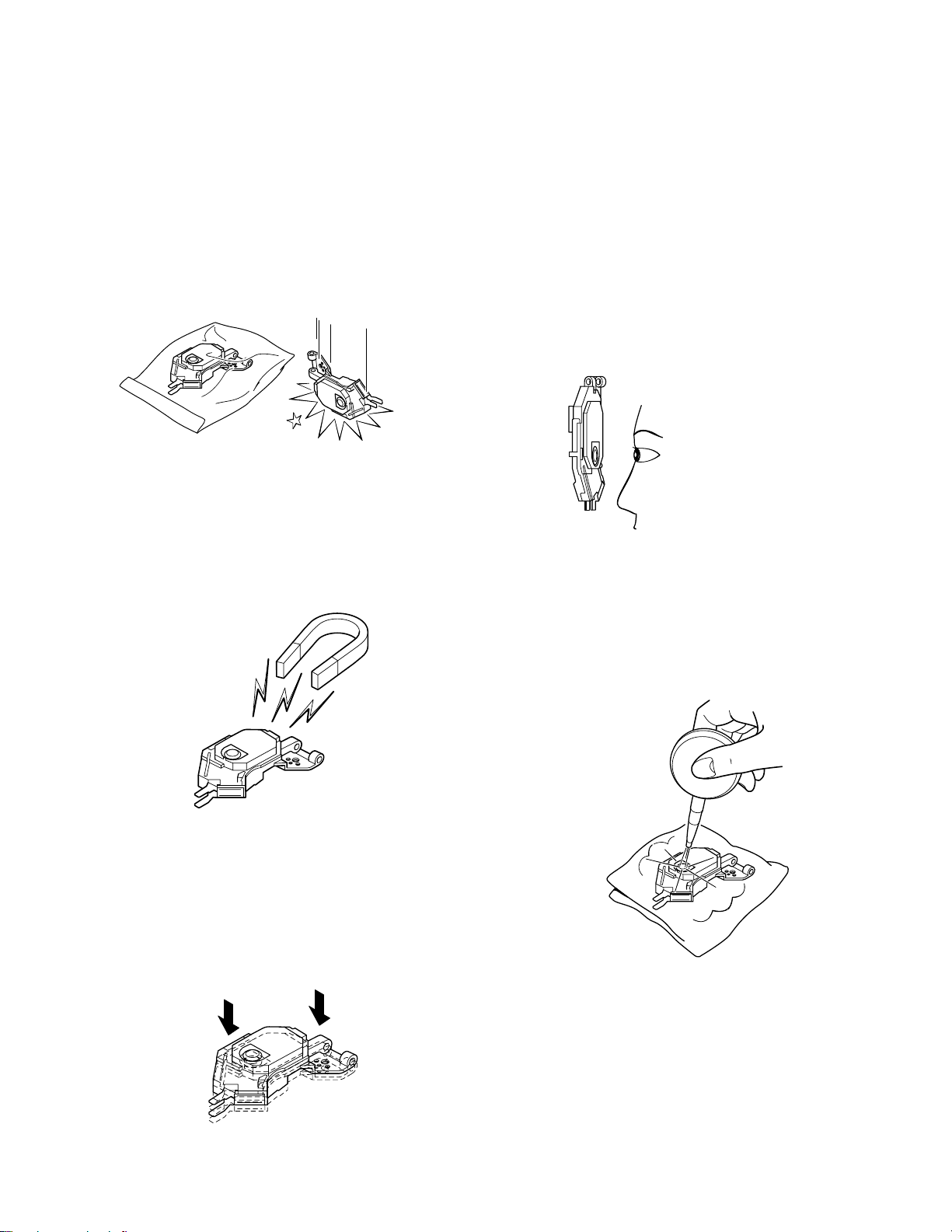
LASER BEAM SAFETY PRECAUTIONS
NOTES FOR TRANSPORT AND STORAGE
1. The pickup should always be kept in its conductive bag
until use.
2. The pickup should never be subjected to external pressure or impact.
Storage in conductive bag Drop impact
GOOD
REPAIR NOTES
1. The pickup incorporates a strong magnet, and so should
never be brought close to magnetic materials.
NG
3. Each and every pickup is already individually adjusted to
a high degree of precision, and for that reason the adjustment point and installation screws should be absolutely
never be touched.
4. Laser beam may damage the eyes!
Absolutely never permit laser beams to enter the eyes!
Also NEVER switch ON the power to the laser output part
(lens, etc.) of the pickup if it is damaged.
Laser Beam
NEVER look directly at the
laser, and do not let contact
fingers of other exposed
skin.
NG
Magnet
NG
2. The pickup should always be handled correctly and carefully, taking care to avoid external pressure and impact. If
it is subjected to strong pressure or impact, the result may
be an operational malfunction and/or damage to the
printed circuit board.
Pressure
Pressure
5. Cleaning the lens surface
If there is dust on the lens surface, the dust should be
cleaned away by using an air brush (such as one used for
camera lens). The lens is held by a delicate spring.
Conductive Sheet
6. Never attempt to disassemble the pickup.
— 2 —
Page 5
SERVICE NOTE AND PRECAUTIONS
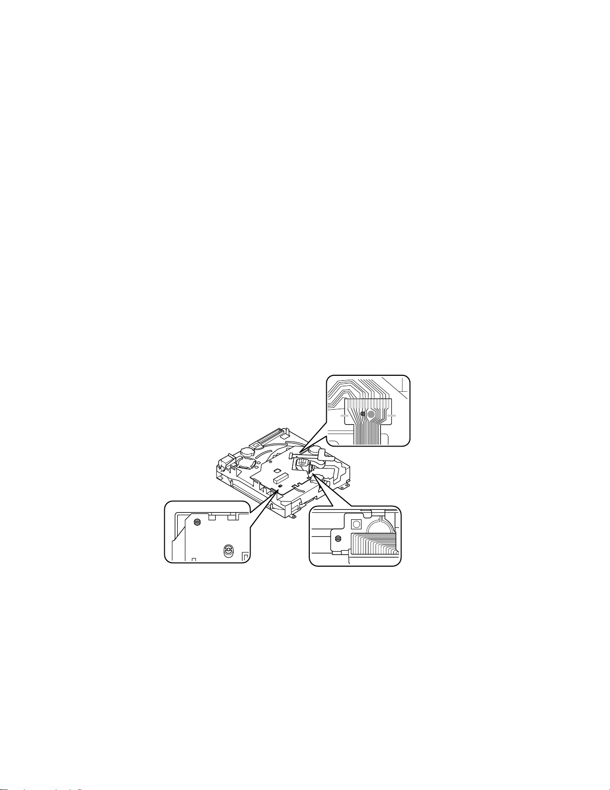
STATIC ELECTRICITY
The CD pickup might suffer destruction by static electricity during spare-parts maintenance or replacement, although it is stable
when connected to the circuit in the CD unit. The destruction might be caused because the laser diode terminal will be electrically open. To prevent the terminal from being open, do the following steps:
1. When you replace the CD pickup, or remove the CD unit from the car stereo unit for any maintenance purpose, solder the
copper foil pattern indicated in Fig. 1 and Fig. 2 below to short-circuit the connector PCB and flexible wire of the CD unit.
Perform your intended maintenance work with the flexible wire short-circuited.
2. If the original CD pickup may possibly be reused, make a short circuit in the area indicated in Fig. 3 first. Then remove the
pickup and perform the work.
3. The CD Pickup OPTIMA-715K2, which is supplied as one of the spare parts, is already short-circuited with the copper foil
pattern pre-soldered indicated in Fig. 3 below. To handle this CD Pickup, keep the short circuit as it is. Then attach the
Pickup to the unit and connect the flexible wire to the connector.
4. After performing the work, eliminate the short circuit by removing the solder at its respective short-circuited area described
in 1, 2 and 3 above.
5. Insert a CD. If the E-01 or E-02 error should appear on the display on the face plate, check the area mentioned in 4 above,
where the short circuit may not have been eliminated.
6. Note that the semi-fixed VR equipped with the CD Pickup OPTIMA-715K2 must not be turned. You cannot make any
adjustment to the semi-fixed VR, which is completely adjusted when shipped at the factory.
Fig. 3Fig. 2
Fig. 1
— 3 —
Page 6
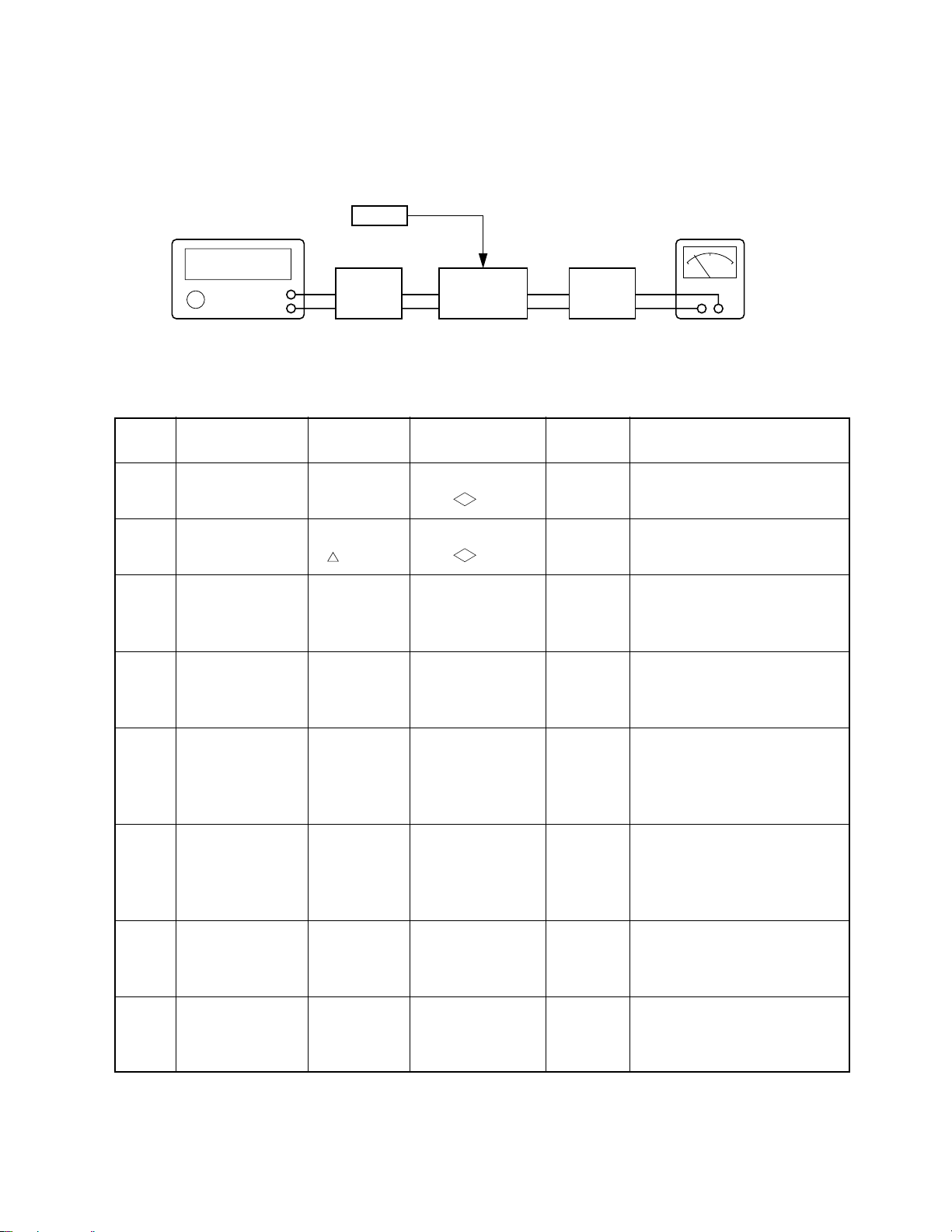
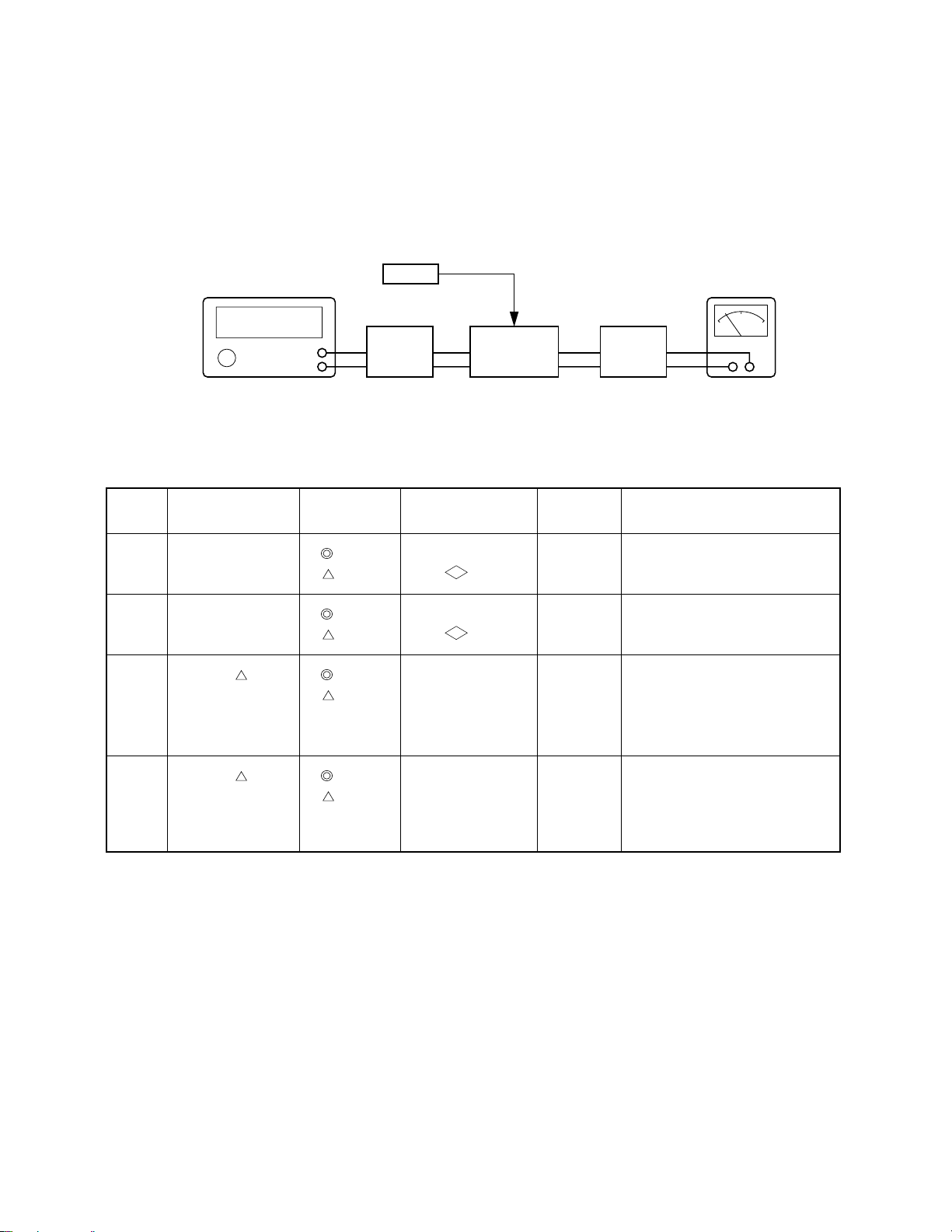
ELECTRICAL ADJUSTMENTS
ALIGNMENT OF FM RF & IF SECTION
Set the radio for FM reception. FM signal generator should be coupled with antenna receptacle, through dummy.
STEP
1
2
3
FM SG
&
STEREO SG
GENERATOR
FREQUENCY
Non-Mod.
Non-Mod.
98.1MHz
1kHz, 22.5kHz dev.
SG att:66dBµ EMF
VTVM
*1 *2
FM
DUMMY
ANTENNA
T.P
SET
DUMMY
LOAD &
SW BOX
*1 :Refer to “DUMMY BOX SCHEMATIC” (Page 10) Fig.11-2
*2 :Refer to “DUMMY BOX SCHEMATIC” (Page 10) Fig.11-3
Fig. 4 * SG frequency should be as accurate as possible.
RADIO DIAL
SETTING
87.5MHz
107.9MHz
108MHz
98.1MHz
OUTPUT
INDICATOR
DC VTVM to test
VT
point
DC VTVM to test
VT
point
AC VTVM to test
point*
ADJUST-
MENT
—
L103
FM OSC
L110
FM DET
Check the voltage over than
1.1 V.
Adjust for 6.9±0.1V
NULL VOLTAGE to become
-20±20mV.
DISTORTION METER
AC VOLTMETER
REMARKS
4
98.1MHz
1kHz, 22.5kHz dev.
SG att:6dBµ EMF
5
98.1MHz
1kHz, 22.5kHz dev.
SG att:6dBµ EMF
98.1MHz
88.5MHz
AC VTVM across
speaker or 4 ohms
load
AC VTVM across
speaker or 4 ohms
load
L107
FM MIX
L110
FM ANT
L102
FM RF
6
88.5MHz
107.9 (108)MHz
SG att:6dBµ EMF
87.5MHz
107.9 (108.0)
MHz
AC VTVM across
speaker or 4 ohms
load
L100
FM ANT
L102
FM RF
7
98.1MHz
SG att:25dBµ EMF
98.1MHz
TEST MODE
Adjust so that the
*2
“ST” mark of LCD
R129
FM SD
Display appears
7*
RDS
98.1MHz
1kHz, 22.5kHz dev.
SG att:33dBµ EMF
98.1MHz
TEST MODE
Adjust like to appear
*2
for 0.95 of LCD
Display
R204
*1 : Perform step 6 after MPX adjustment of the following page (page 6).
*2 : Setting up TEST MODE at page 7.
Adjust for Maximum output Level.
Adjust for Maximum output Level.
Check for SPEC.
Sensitivity of the seeking frequency.
Sensitivity of the S meter.
— 4 —
Page 7
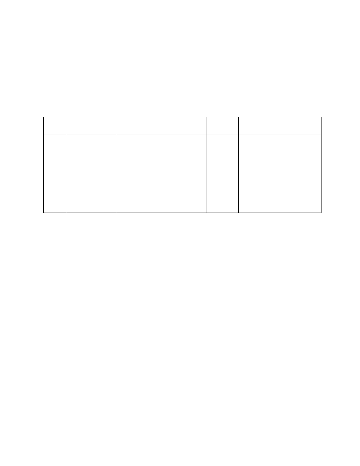
ELECTRICAL ADJUSTMENTS
ALIGNMENT OF AM RF & lF SECTION
Set the radio for AM reception. AM signal generator should be coupled with antenna receptacle through dummy.
Set VOLUME control to maximum and TONE to center. Attenuate signal generator output to maintain 0.5 watts (1.4 volts across
4 ohms load) on AC voltmeter.
STEP
1
2
3
AM SG
&
STEREO SG
GENERATOR
FREQUENCY
Non-Mod.
Non-Mod.
1000kHz, 999kHz
400Hz
30% MOD
SG att: 20dBµ EMF
ANTENNA
RADIO DIAL
SETTING
530kHz
531kHz
1710kHz
1602kHz
1000kHz
999kHz
VTVM
*1 *2
AM
DUMMY
T.P
SET
DUMMY
LOAD &
SW BOX
DISTORTION METER
AC VOLTMETER
*1 :Refer to “DUMMY BOX SCHEMATIC” (Page 10) Fig.11-1
*2 :Refer to “DUMMY BOX SCHEMATIC” (Page 10) Fig.11-3
Fig. 5 * SG frequency should be as accurate as possible.
OUTPUT
INDICATOR
DC VTVM to test
VT
point
DC VTVM to test
VT
point
AC VTVM across
speaker(L or R) or 4
ohms load
ADJUST-
MENT
—
—
L108
AM IFT1
L111
AM IFT2
REMARKS
Check the voltage over than 2.5V.
Check the voltage less than 7.5V.
Adjust for Maximum output Level.
4
1000kHz, 999kHz
400Hz
30% MOD
TEST MODE*
SG att: 30dBµ EMF
* Setting up TEST MODE at page 7.
1000kHz
999kHz
Adjust so that the
“ST” mark of LCD
Display appears
— 5 —
R124
AM SD
Sensitivity of the seeking frequency.
Page 8
ELECTRICAL ADJUSTMENTS
ALIGNMENT OF FM MULTIPLEX SECTION
FM signal generator should be modulated by FM stereo signal generator.
Modulation level: 19kHz 10% (7.5kHz dev)
1000Hz 30% (22.5kHz dev)
FM signal generator output level: 66dBµ (1mV)
Frequency: 98.1 MHz.
Set the radio for FM reception and tune to signal. Adjust volume control to provide 0.5 watt on AC VTVM and tone to center. Set
L/R balance control for equal output at each channel.
STEP
1
2
3
MODULATION
FREQUENCY
19kHz & 1000Hz
(Left Channel)
SG att:66dBµ EMF
19kHz & 1000Hz
(Right Channel)
19kHz & 1000Hz
(Left Channel)
SG att:45dBµ EMF
OUTPUT INDICATOR
AC VTVM across Right speaker or
Right channel load
AC VTVM through Left speaker or
Left channel load
AC VTVM across Right speaker or
Right channel load
ADJUST-
MENT
R137
R137
R156
REMARKS
Adjust for minimum.
Check for minimum.
Adjust for 20dB Separation.
— 6 —
Page 9
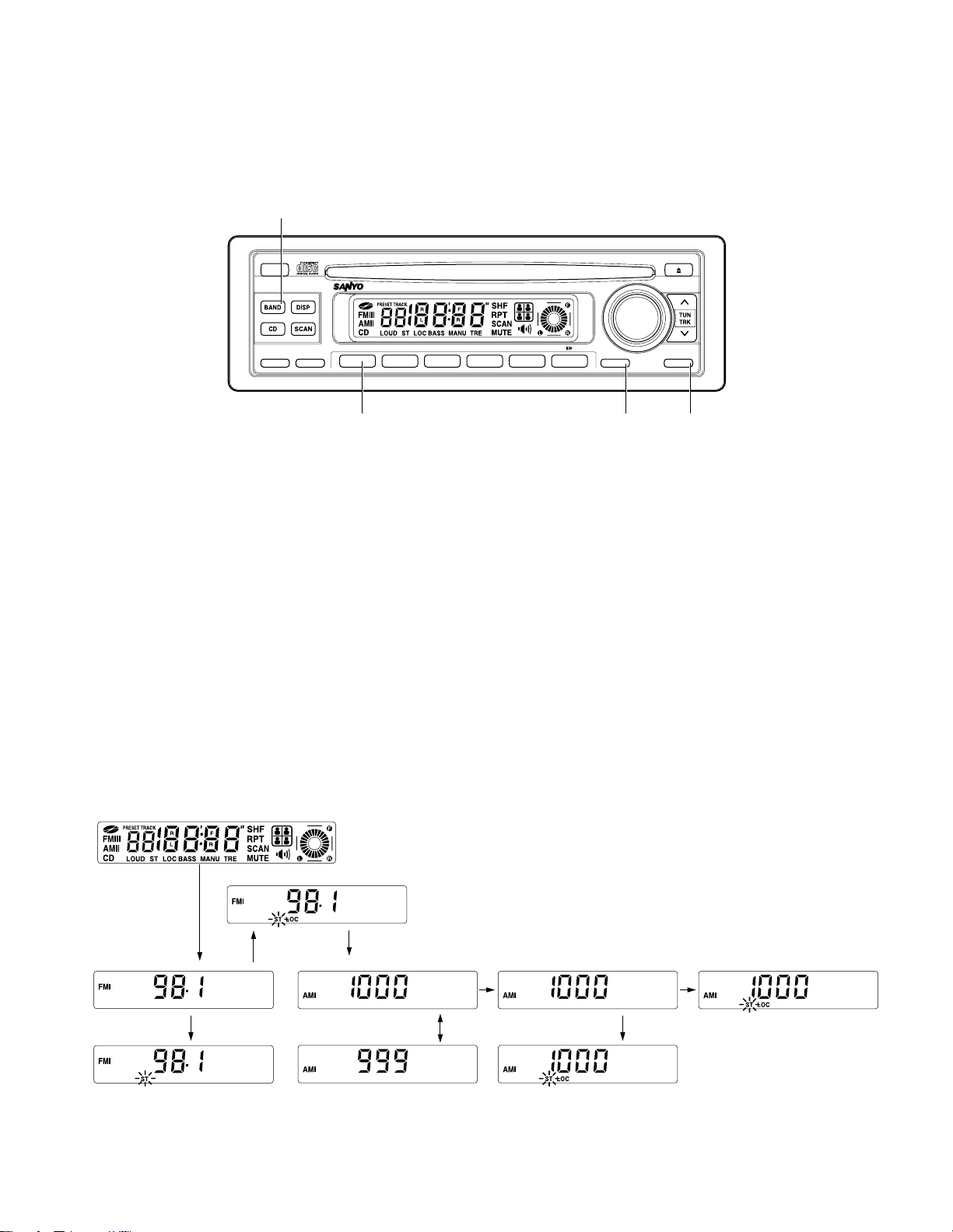
ELECTRICAL ADJUSTMENTS
w
FOR FXD-780GD
SETTING UP TEST MODE AT STEP 4 FOR AM & STEP 7 FOR FM
Press the e
to set the mode to the test mode shown in Step 4 for AM and Step 7 for FM.
POWER
button to turn the power off. Next, use the following procedure with the front panel switches
REL
ATP
BAS-X
LO/DX
LOUD
FM/AM CD RECEIVER FXD-780GD 50W x 4
1
23456
RPTSHF
VOL
AUDIO
MUTE
POWER
TUNTUN
TRKTRK
erq
Fig. 6
1. While the power is off, press the q
neously to enable the w
BAND
PRESET 1
button. Then press the w
BAND
button and e
button to be used at the moment the power comes on.
POWER
button simulta-
2. If the above operation is successful all the figures on the LCD light up, check that you have entered test mode. Fig. 7 (A).
3. Press the r
AUDIO
button once. The display shown in Fig. 7 (B) appears on the LCD and the unit enters DX mode.
Then, while receiving FM 98.1MHz rotate the Semi-fixed VR R129 on the TUNER UNIT (RF33) to adjust the LCD until the
stereo mark light “
4. Press the r
ST
” is on. Fig. 7 (B)’.
AUDIO
button, if the display changes to that shown in Fig. 7 (C) the unit is in Local mode. Check that the “
ST
” mark
is displayed (for specific: Input level is 12 ~ 28dB higher than that of the DX mode).
5. Press the w
6. Then press the r
fixed VR R124 on the TUNER UNIT (RF33) to adjust the LCD until “
7. Then press the r
“
ST
” mark is displayed. (for specific: Input level is 12 ~ 28dB higher than that of DX mode).
BAND
button, if the display changes to that shown in Fig. 7 (D) or (D)’ receiving AM 1000 kHz or *(999) kHz.
AUDIO
button, if the display changes to that shown in Fig. 7 (E) the unit is in DX mode. Rotate the Semi-
ST
” mark lights up.
AUDIO
button, if the display changes to that shown in Fig. 7 (F) the unit is in Local mode. Check that the
8. Turn off the power to release the test mode.
TEST MODE CHART
(A) Enter the Test Mode
(C) FM Local Mode OK
(B) FM DX Mode
(B’)OK
(D) Receiving 1000kHz
(D’) Receiving 999kHz
(E) AM DX Mode
(F) AM Local Mode
Fig. 7
— 7 —
(E’)OK
Page 10
TEST MODE CHART
tw
(A) Enter the Test Mode
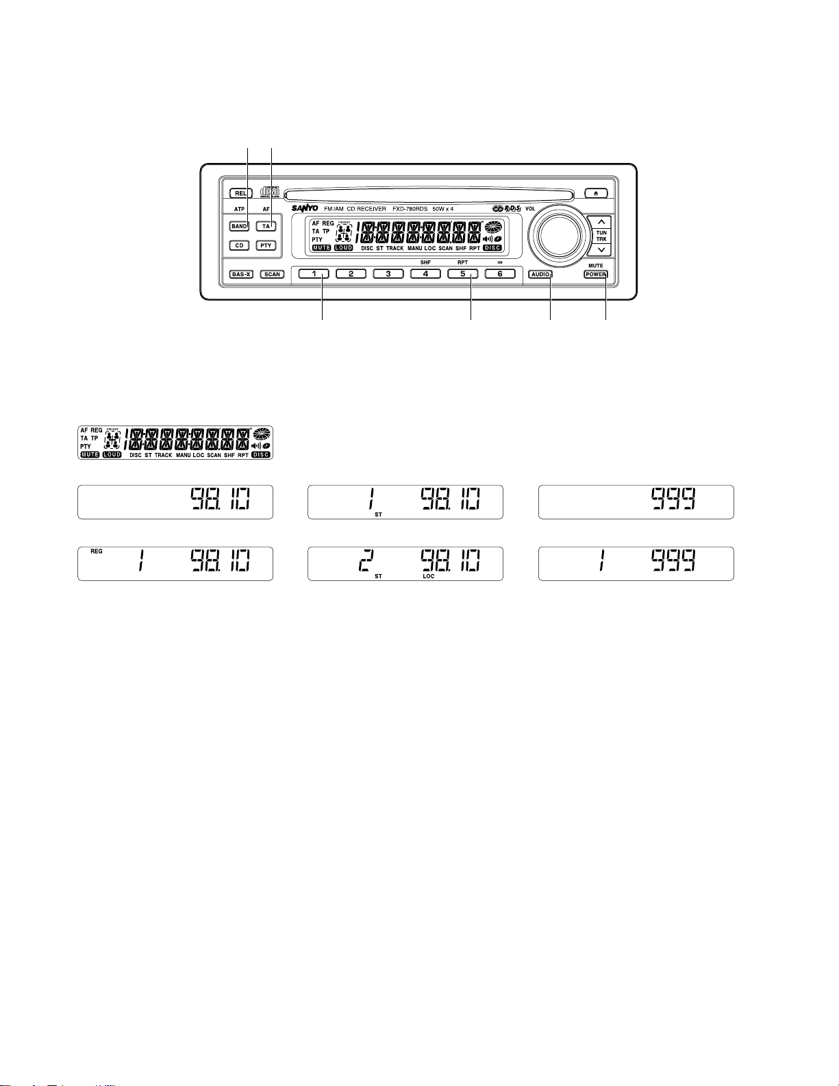
ELECTRICAL ADJUSTMENTS
FOR FXD-780RDS
r eq y
Fig. 8
(B) Enter the FM Mode
(C) FM DX Mode
1. While the power is off, press the q
simultaneously. All the figures on the LCD lights up Fig. 9 (A) enters the TEST mode.
2. Press the r
Rotate the R129 on the PC Board Ass’y (RF33R) to adjust the LCD until the STEREO indicator lights up. Fig. 9 (D)
3. Press the r
displayed (for specific: Input level of Signal Generator is 12 ~ 28dB higher than that of the DX mode). Fig. 9 (E)
4. By pressing the w
5. Press the r
Rotate the R124 on the PC Board Ass’y (RF33R) to adjust the LCD until the STEREO indicator lights up. Fig. 10 (H).
AUDIO
AUDIO
AUDIO
button after step 1, the unit enters FM seek adjust mode of the DX mode. Fig. 9 (C)
button again after step 2, the unit enters the LOCAL mode. Check that the STEREO indicator is
BAND
button in the steps 1 to 3 enters the unit to the AM mode. Fig. 9 (F)
button, the unit enters SEEK adjustment mode of the DX mode. Fig. 9 (G)
(D) Receiving 98.1 MHz
(E) FM Local Mode
PRESET 1
button. Then keep pressing the w
Fig. 9
(F) Enter the AM Mode
(G) AM DX Mode
BAND
button, press the e
POWER
button
6. Pressing the r
displayed (for specific: Input level of Signal Generator is 12 ~ 28dB higher than that of the DX mode). Fig. 10 (I)
AUDIO
button again after step 5, the unit enters th LOCAL mode. Check that the STEREO indicator is
— 8 —
Page 11
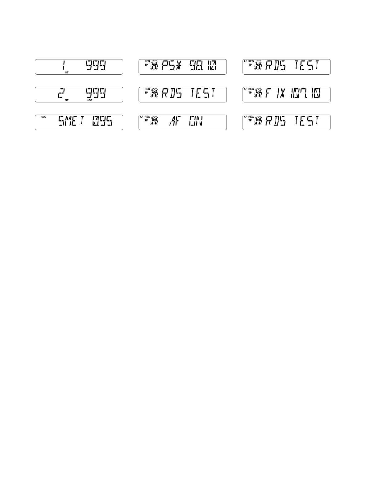
(H) Receiving 999 kHz
(K) The Moment TP ON
(N) Change the Display while AF ON
(I) AM Local Mode
(J) S. Meter Adj. Mode
(L) Change the Display while TP ON
(M) The Moment AF ON
Fig. 10
7. Press the t
TA
button in the step 1, the unit enters the S meter adjustment mode. Rotate the R208 on Main PCB to adjust
the LCD until the 0.95 lights up. Fig. 10 (J)
8. e
9. e
POWER
POWER
OFF and ON. Release the test mode.
OFF and press the y
PRESET 5
.
SG 98.1 MHz, MOD. 75kHz, INT MOD. EXT, att 66dBµ
RDS 1.0%, MOD. 30% 1 kHz, MONO, RDS ON, TP ON, SK OFF, BK OFF.
10. Confirm the “
TP
” indicator on the LCD lights up.
Fig. 10 (K) 씮 (L) soon. So RDS ON Sensitivity is OK.
(O) The Moment 107.1 MHz Receiving
(P)
Change the Display while 107.1 MHz Receiving
11. Press the q
12. Press the t
PRESET 1
TA
button for more than 2 seconds and confirm the “
button for more than 2 seconds. (Memorize the RDS).
AF
SG 107.1 MHz, MOD. 75kHz, INT MOD. EXT, att 66dBµ
RDS 1.6%, MOD. 30% 1 kHz, MONO, RDS ON, TP ON, SK OFF, BK OFF.
13. Press the q
PRESET 1
button. Confirm the receiving 107.1 MHz automatically. So the LCD indicator displays Fig. 10 (O) 씮
(P).
” indicator on the LCD lights up. Fig. 10 (M) 씮 (N) soon.
— 9 —
Page 12
ELECTRICAL ADJUSTMENTS
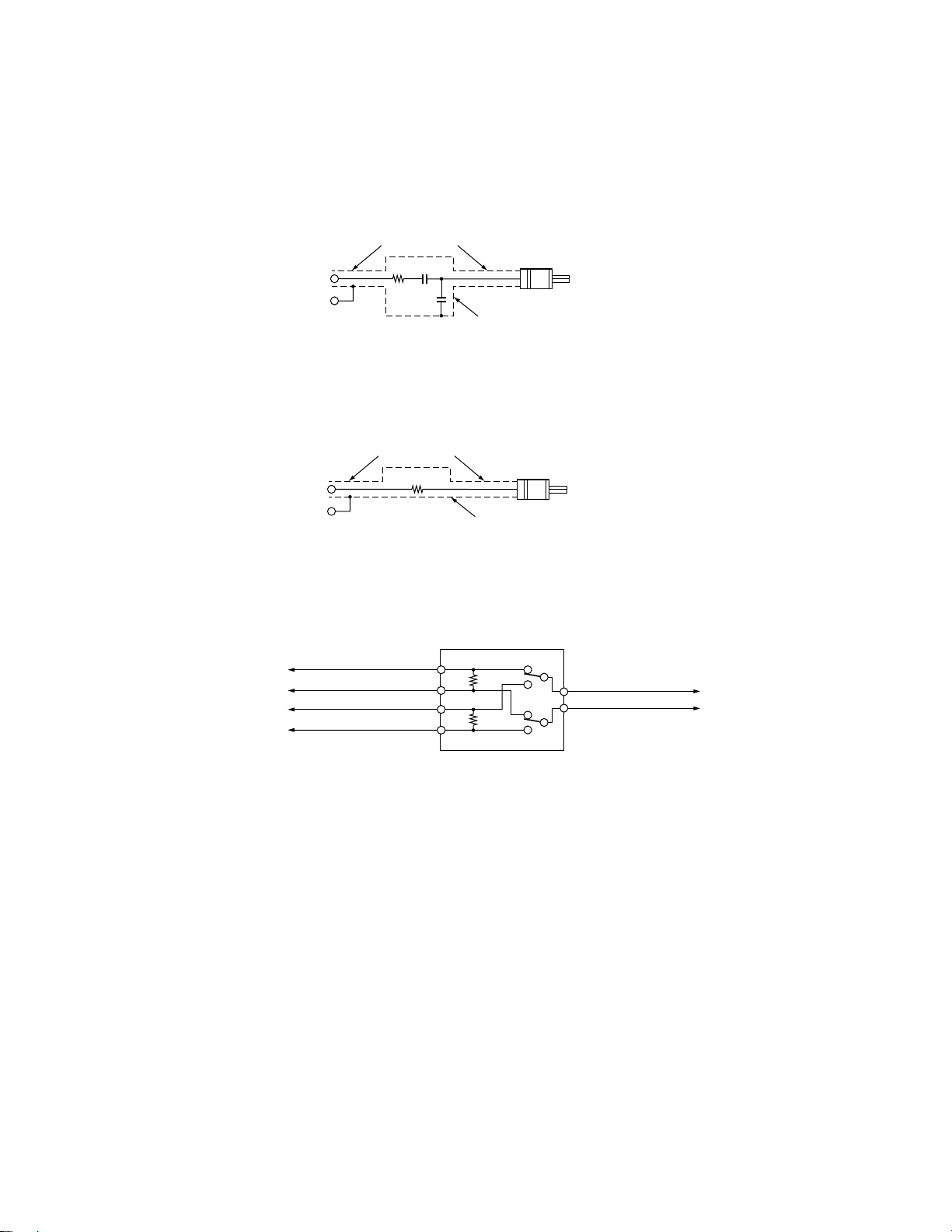
DUMMY BOX SCHEMATIC
쎲 AM DUMMY ANTENNA
PLUG TO FIT ANTENNA
RECEPTACLE OF UNIT
METAL SHIELD CAN
AM S.G.
(50Ω)
CO-AX CABLE
30Ω 15PF
60PF
Fig. 11-1
쎲 FM DUMMY ANTENNA
PLUG TO FIT ANTENNA
RECEPTACLE OF UNIT
METAL SHIELD CAN
FM S.G.
(50Ω)
CO-AX CABLE
25Ω
Fig. 11-2
쎲 DUMMY LOAD & SWITCH BOX (FOR STEREO UNIT)
4Ω 20W
LEFT CHANNEL OUTPUT
UNIT
RIGHT CHANNEL OUTPUT
4Ω 20W
L
R
L
R
AC V.T.V.M. OR SCOPE
Fig. 11-3
— 10 —
Page 13
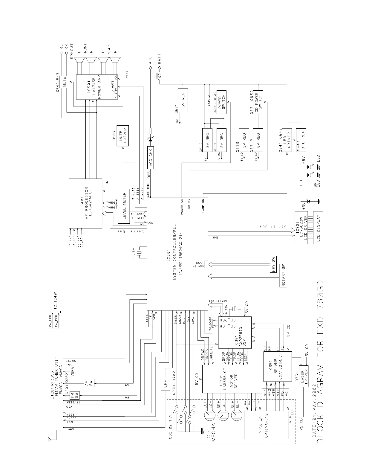
BLOCK DIAGRAM
FOR FXD-780GD
— 11 —
Page 14
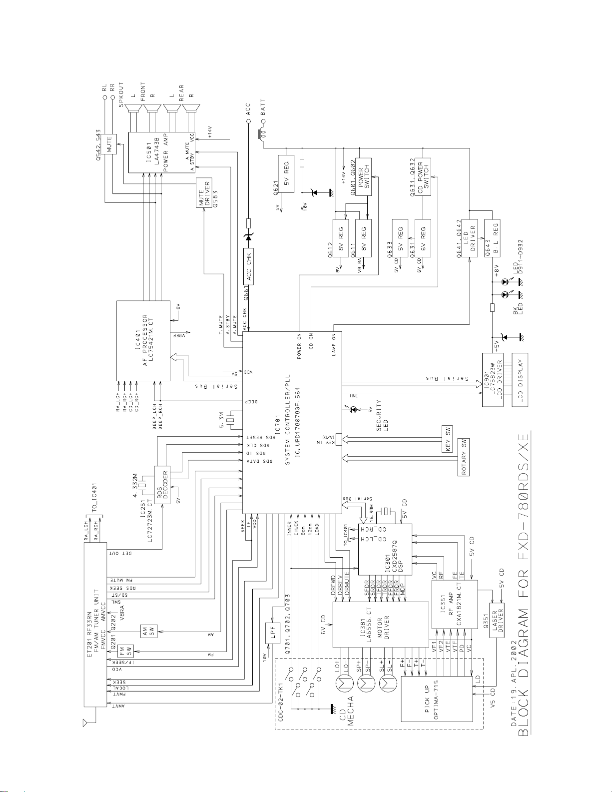
BLOCK DIAGRAM
FOR FXD-780RDS
— 12 —
Page 15
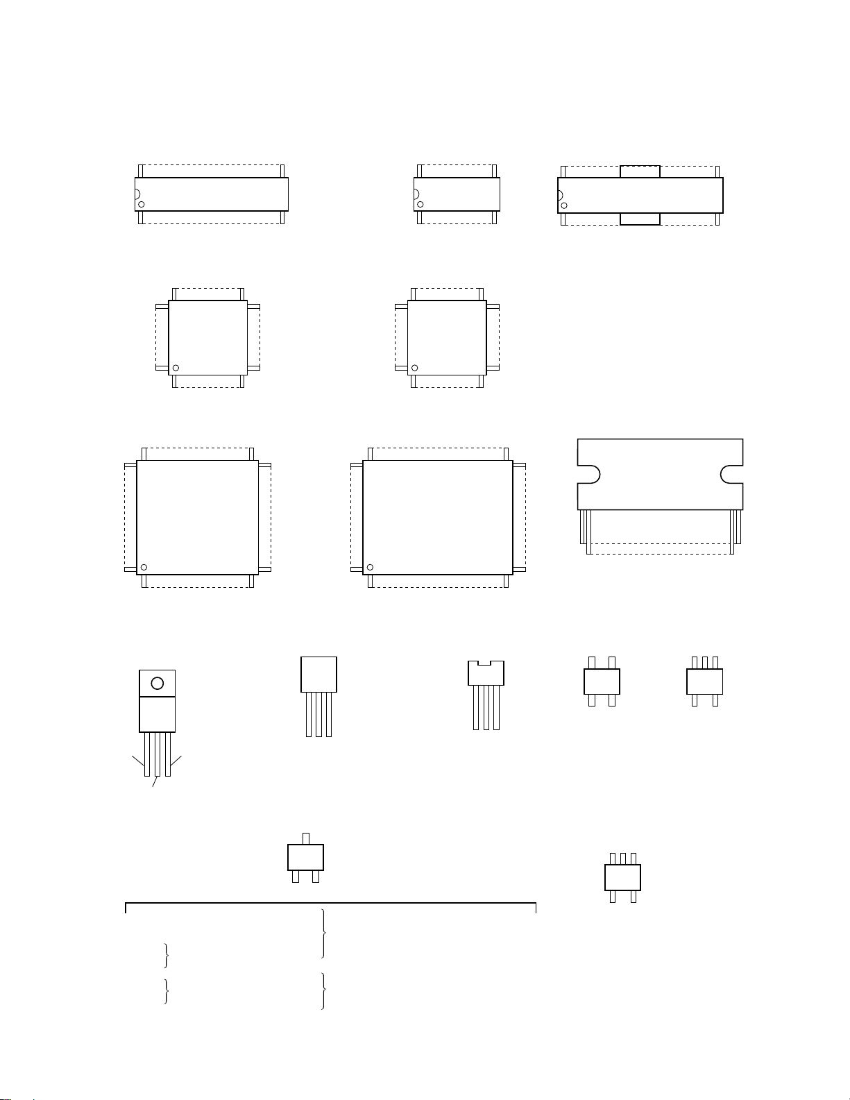
IC/TRANSISTOR LEAD IDENTIFICATION
TOP VIEW or SIDE VIEW
FOR FXD-780GD
36 19
118
IC401 : LC75421M-CT
48
1
IC901 : LC75823W
60
61 40
33
3249
1764
16
41
61 40
60
20 11
110
IC351 : CXA1821M-CT IC381 : LC6556-CT
48
1
IC101 : LA178IM
33
3249
1764
16
41
36
1
19
18
80 21
1
IC301 : CXD2587Q
IN
GND
IC631: KIA7806API
Q105 : 2SC4081T106-Q, R
Q106 : DTC114TKAT
Q661
Q702
Q542
Q543
OUT
2SC2412KT-Q, R
DTC143TKAT
20
Q612: KTC3199T-Y, GR
Q621: KTC3199T-Y, GR
Q633: 2SD1468ST-R, S
C
B
Q201
Q202
Q583
Q641
Q602
Q632
Q642
80 21
1
IC701 : UPD178024GC
ECB
E
Q351: 2SB815T-B6, B7
DTA124EKAT
Q701: 2SD21030TX-T
Q643: 2SD2375-Q, P
DTC124EKAT
ECB
Q601: 2SB1326T-R
Q611: 2SD1858T-Q, R
Q631: 2SB1326T-Q, R
20
1 25
IC501 : LA4743B
G2 G1
DS
Q100: 3SK263T-5
A
KK
KK
D901 : HZM6.2Z FA
Q111: FC18T-F, G
E/D
BS
CG
— 13 —
Page 16

IC/TRANSISTOR LEAD IDENTIFICATION
TOP VIEW or SIDE VIEW
FOR FXD-780RDS
36 19
118
IC401 : LC75421M-CT
48
1
IC901 : LC75823W
60
61 40
33
3249
1764
16
41
61 40
60
20 11
110
IC351 : CXA1821M-CT IC381 : LC6556-CT
48
1
IC101 : LA178IM
33
3249
1764
16
41
36
1
24 13
112
IC251 : LC72723M-CT
19
18
80 21
1
IC301 : CXD2587Q
IN
GND
IC631: KIA7806API
Q105 : 2SC4081T106-Q, R
Q661 : 2SC2412KT-Q, R
Q542
Q543
Q106
Q110
Q117
OUT
DTC143TKAT
DTC114TKAT
20
Q612: KTC3199T-Y, GR
Q621: KTC3199T-Y, GR
Q633: 2SD1468ST-R, S
ECB
C
BE
Q201
Q202
Q583
Q641
Q602
Q632
Q642
80 21
1
IC701 : UPD178078GF
ECB
Q601: 2SB1326T-R
Q611: 2SD1858T-Q, R
Q631: 2SB1326T-Q, R
Q351: 2SB815T-B6, B7
DTA124EKAT
Q701: 2SK1581T
Q643: 2SD2375-Q, P
DTC124EKAT
20
1 25
IC501 : LA4743B
G2 G1
DS
Q100: 3SK263T
A
KK
KK
D901 : FTZ6.8E
Q116 : 2SK303T-3, 4
Q115 : DTA114EKAT
G
SD
E/D
BS
CG
Q111: FC18T-F, G
OUT
IN G
— 14 —
Page 17

CD MECHANISM EXPLODED VIEW
(MECHANISM #5BB002)
126
61
125
158
123
98
47
68
48
28
80
31
38
37
29
79
98
46
153
158
45
49
57
86
64
63
92
74
30
77
10
94
75
92
7
147
23
32
78
93
92
88
152
39
12
18
34
85
87
6
134
156
21
56
133
99
22
154
67
74
35
53
1
50
147
84
97
145
2
109
116115
112
113
142
70
36
43
150
92
41
42
11
141
76
92
127
135
105
44
105
148
9
92
40
NOTE:
Parts from the deck mechanism exploded view and parts list are only for technical reference. These parts may or may not be
individually available.
— 15 —
Page 18

CABINET & CHASSIS EXPLODED VIEW
!0
o
!2
!3
!1
!4
u
!4
!9
!6
!4
!4
@3
!7
y
t
!9
!7
ET201
w
!7
q
A
B
y
t
@3
!8
r
A
!7
!8
@2
!8
@1
!8
(For FXD-780GD/SS, BK.SS)
BRACKET(MOUNT)
TK21176533
BKT(REL)
TK21176780
CABLE ASS'Y
(E-1)
TK26917170
(For FXD-780RDS/XE)
TK26917002
SUPPORT BKT
TK2102013
SCREW KIT(6PCS)
TK29X12210
!8
!8
!8
B
!5
@0
!8
i
e
— 16 —
Page 19

PARTS LIST
CABINET & CHASSIS
Ref.No. PartsNo. Description
1 TK5BB002 CD DECK MECHANISM (5BB002)
2 TK21035410 CHASSIS ASSY
3 TK21047080 COVER
4 TK21145190 HEATSINK (2P)
5 TK21176820 BKT (STOPPER)
6 TK21291290 PLATE SPRING (REL)
7 TK22060530 ESC ADAPT OR (FXD-780GD/SS)
TK22060520 ESC ADAPT OR (FXD-780GD/BK.SS)
TK22060530 ESC ADAPT OR (FXD-780RDS/XE)
8 TK28004780 INSULATOR
9 TKAKC436G9C FPPART FXD-780GD/SS (FXD-770GD/SS)
TKAKC437G9C FPPART FXD-780GD/BKSS (FXD-770GD/BK.SS)
TKAKC439G9C FPPART FXD-780RDS/XE (FXD-780RDS/XE)
10 TK22331951 FPASSY (A) 780GD/SS (FXD-780GD/SS)
TK22331991 FPASSY (A) 780GD/BK.SS (FXD-780GD/BK.SS)
TK22331961 FPASSY (A) 780RDS/XE (FXD-780RDS/XE)
11 TK22240690 FACE PLATE (B)
12 TK35V49A0 DISPLAY CIRCUIT BOARD (FXD-780GD/SS, BK.SS)
TK35V55A0 DISPLAY CIRCUIT BOARD (FXD-780RDS/XE)
13 TK22900510 KNOB (VOL) ASSY (FXD-770GD/SS, FXD-780RDS/XE)
TK22900800 KNOB (VOL) ASSY (FXD-770GD/BK.SS)
14 TK29A5208C TPB2-2X8SSC
15 TK35V44C0 MAIN CIRCUIT BOARD (FXD-780GD/SS, BK.SS)
TK35V49A0 DISPLAY CIRCUIT BOARD (FXD-780GD/SS, BK.SS)
ET201 TK37315B0 BL ASSY RF33SS (FXD-780GD/SS, BKSS)
15 TK35V48C0 MAIN CIRCUIT BOARD (FXD-780RDS/XE)
TK35V55A0 DISPLAY CIRCUIT BOARD (FXD-780RDS/XE)
ET201 TK37314B0 BL ASSY RF33RN (FXD-780RDS/XE)
16 TK22331901 FPASSY (C) SANYO (FXD-780GD/SS, BK.SS)
TK22331921 FPASSY (C) SANYO (FXD-780RDS/XE)
17 TK2952265A DPBS-2.6X5SSA
18 TK2952266A DPBS-2.6X6SSA
19 TK2952266C DPBS-2.6X6SSC
20 TK2952268A DPBS-2.6X8SSA
21 TK295226BA DPBS-2.6X12SSA
22 TK2956308A DPPB-3X8SSA
23 TK2958266A DPSS-2.6X6SSA
— 17 —
Page 20

ACCESSORY
Ref.No. PartsNo. Description
— TK2102013 SUPPORT BKT
— TK21176533 BKT (MOUNT)
— TK21176780 BKT (REL)
— TK22720890 C.CASE ASSY (FXD-780GD/SS, BK.SS)
— TK22720891 C.CASE ASSY (FXD-780RDS/XE)
— TK26917170 CABLE ASSY (E-1) (FXD-780GD/SS, BK.SS)
— TK26917002 CABLE ASSY (P-54C) (FXD-780RDS/XE)
— TK28585540 GIFT BOX 780GD/SS (FXD-780GD/SS)
— TK28585550 GIFT BOX 780GD/BKSS (FXD-780GD/BK.SS)
— TK28585560 GIFT BOX 780RDS/XE (FXD-780RDS/XE)
— TK28940750 & M.KIT 780GD/SS (FXD-780GD/SS, BK.SS)
— TK28940760 & M.KIT 780RDS/XE (FXD-780RDS/XE)
— TK29X12210 SCREW KIT
— 18 —
Page 21

PARTS LIST-CD MECHANISM
Ref. No. Part No. Description
1 TKX10071011 CHASSIS ASSY (TK1)
2 TKX10071005 PICK BASE ASSY
6 TK110051003 CHUCK ARM
7 TK110051004 TOP COVER
9 TK110051006 L.M BRACKET
10 TK110051007 CLAMPER PLATE
11 TK110051008 R ARM
12 TK110051009 RELEASE LEVER
18 TK110051018 SET START ARM
21 TK110071003 SPG GUIDE
22 TK110071004 PICK GUIDE
23 TK110071008 L PLATE
28 TK110052002 CAM GEAR
29 TK110052003 CAM SUB GEAR
30 TK110052004 CLAMPER
31 TK110052005 DISC ARM L
32 TK110052006 DISC ARM R
34 TK110052008 DISC TABLE
35 TK110052009 FEED GEAR A
36 TK110052011 FEED MOTOR GEAR
37 TK110052012 LOAD HELICAL GEAR
38 TK110052013 LOAD GEAR
39 TK110052014 CAM H GEAR
40 TK110052016 KICK LEVER
41 TK110052017 LEVER R
42 TK110052018 LOCK LEVER
43 TK110052019 MOTOR CASE
44 TK110052020 MOTOR WORM
45 TK110052021 ROLLER GEAR
46 TK110052022 SENSOR LEVER
47 TK110052023 TOP GUIDE
48 TK110052024 UP LEVER
49 TK110052025 SW LEVER
50 TK110052027 KICK SUB LEVER
53 TK110052030 FEED GEAR B
56 TK110072002 GUIDE
57 TK110072003 P.B. LOCK
61 TK110053006 ROLLER SHAFT
63 TK110053025 DISC ARM PIN
64 TK110053026 DISC ARM ROLLER
67 TK110073001 FEED SCREW
68 TK110073003 COLLAR
70 TK110073012 FPC PIN
74 TK110054003 DAMPER SP
75 TK110054004 DISC ARM SP
76 TK110054005 LEAD SP
77 TK110054007 SENSOR LEVER SP
78 TK110054008 DAMPER SUB SP
79 TK110054009 SUB GEAR SP
— 19 —
Page 22

PARTS LIST-CD MECHANISM
Ref. No. Part No. Description
80 TK110054010 UP LEVER SP
84 TK110074001 FEED SP
85 TK110074002 CHUCK ARM SP (L)
86 TK110074003 P.B. LOCK SP
87 TK110074004 CHUCK ARM SP (R)
88 TK110074014 STARTSP (B)
92 TK110055003 XP SCREW
93 TK110055004 ARM SHEET
94 TK110055005 CHUCK SHEET
97 TK110075001 DISC SHEET
98 TK110075005 LOADING ROLLER
99 TK1 10075003 FPC TAPE
105 TK110076002 DAMPER ASSY (T)
109 TK110057007 INNER SW ALPS
112 TK110057011 MOTOR LEAD A
113 TK110057012 MOTOR LEAD B
115 TK110057014 SW LEAD A
116 TK110057015 SW LEAD B
123 TK110057049 SENSOR PCB
125 TK110057076 LOAD SW MIC
126 TK110057077 CORD 3P (D)
127 TK110057078 MOTOR LEAD 2P
133 TK110077006 PICK K2 JVC
134 TK110077007 SPINDLE MOTOR MABUCHI
135 TK110077008 LOAD MOTOR (11) MABUCHI
141 TKX10077030 DUMMY PCB ASSY (TK)
142 TK110027003 MAIN MOTOR MABUCHI
145 TK110077037 FPC(TK)
147 TK210117022P1 (+)P.PRECISION SCREW #1 M1.7x2.2
148 TK210120025P1 (+)P.PRECISION SCREW #1 M2.0x2.5
150 TK210320040P1 (+)P.PRECISION SCREW #3 M2.0x4.0
152 TK213220040P1 S-TYPE #1 WITH GUIDE M2x4
153 TK213914040P1 B-TYPE M1.4x4
154 TK213917035P1 B-TYPE #3 M1.7x3.5
156 TK213917080P1 B-TYPE M1.7x8
158 TK218160050D2 PSW-S 1.6x5x0.25
— 20 —
Page 23

PARTS LIST
MAIN CIRCUIT BOARD FOR FXD-780GD/SS, BK.SS
Ref.No. PartsNo. Description
AJ201 TK196510300 ANT JACK ASSY
C201, C317 TK157A1020J CAPACITOR, CHIP, 1000PF 50V
C203, C311 TK157A4730J CAPACITOR, CHIP, 0.047UF 16V
C204 TK15715R00J CAPACITOR, CHIP, 5PF 50V
C205, C206 TK157A1830J CAPACITOR, CHIP, 0.018UF 25V
C207 TK157A1040E CAPACITOR, CHIP, 0.1UF 25V
C208 TK15713300J CAPACITOR, CHIP, 33PF 50V
C209, C426 TK15C3106HR CE-RC3-10M16-T58
C302, C308 TK15712210J CAPACITOR, CHIP, 220PF 50V
C303, C307 TK157A1030J CAPACITOR, CHIP, 0.01UF 50V
C304, C705 TK15711010J CAPACITOR, CHIP, 100PF 50V
C305, C312 TK157C1040J CAPACITOR, CHIP, 0.1U
C306, C405 TK15C6105CR CE-RC2-1M50-T58
C309 TK157A3320J CAPACITOR, CHIP, 3300PF 50V
C310 TK157A1520J CAPACITOR, CHIP, 1500PF 50V
C313, C316 TK157C1040J CAPACITOR, CHIP, 0.1U
C314, C315 TK15712200J CAPACITOR, CHIP, 22PF 50V
C318, C319 TK15712210J CAPACITOR, CHIP, 220PF 50V
C320, C708 TK157A1020J CAPACITOR, CHIP, 1000PF 50V
C321, C390 TK15C2107CR CE-RC2-100M10-T58
C322, C391 TK157C1040J CAPACITOR, CHIP, 0.1U
C351, C413 TK15C3106CR CE-RC2-10M16-T58
C352 TK157A1040J CAPACITOR, CHIP, 0.1UF 16V
C353 TK15713R00J CAPACITOR, CHIP, 3PF 50V
C354 TK15714700J CAPACITOR, CHIP, 47PF 50V
C355 TK157C1050J CAPACITOR, CHIP, 1UF 10V
C356, C509 TK15C3476HR CE-RC3-47M16-T58
C381, C382 TK157A1220J CAPACITOR, CHIP, 1200PF 50V
C383, C384 TK157A1220J CAPACITOR, CHIP, 1200PF 50V
C385, C386 TK157A3330J CAPACITOR, CHIP, 333 B
C387, C632 TK157A2230J CAPACITOR, CHIP, 0.022UF 25V
C388 TK157A1530J CAPACITOR, CHIP, 0.015UF 25V
C394, C395 TK157C1040J CAPACITOR, CHIP, 0.1U
C403, C416 TK15C6225HR CE-RC3-2.2M50-T58
C406, C412 TK15C6105HR CE-RC3-1M50-T58
C407, C420 TK157A1220J CAPACITOR, CHIP, 1200PF 50V
C408, C421 TK157A1050J CAPACITOR, CHIP, 1UF 10V
C409, C422 TK157A4730J CAPACITOR, CHIP, 0.047UF 16V
C410, C411 TK157A1540E CAPACITOR, CHIP, 0.15UF 25V
C414, C425 TK15C6105CR CE-RC2-1M50-T58
C419, C505 TK15C6105HR CE-RC3-1M50-T58
C423, C424 TK157A1540E CAPACITOR, CHIP, 0.15UF 25V
C483, C486 TK15C3106CR CE-RC2-10M16-T58
C501, C502 TK15C6474HR CE-RC3-0.47M50-T58
C503, C504 TK15C6474HR CE-RC3-0.47M50-T58
C506, C507 TK15C6105CR CE-RC2-1M50-T58
C508 TK15C6105HR CE-RC3-1M50-T58
C510 TK15C3226CR CE-RC2-22M16-T58
C511 TK15C6224HR CE-RC3-0.22M50-T58
— 21 —
Page 24

MAIN CIRCUIT BOARD FOR FXD-780GD/SS, BK.SS
Ref.No. PartsNo. Description
C512, C601 TK157C1040J CAPACITOR, CHIP, 0.1U
C513 TK15C3338K0 CE-RE3-3300M16
C515, J501 TK165300006 RESISTOR, CHIP, 0OHM 1/16W
C551 TK15091060J CI-1608CH101J100-CT
C581 TK15C6474CR CE-RC2-0.47M50-T58
C582 TK157B1040E CAPACITOR, CHIP, 0.1UF 25V
C611, C633 TK15C2107CR CE-RC2-100M10-T58
C631 TK15C3107CR CE-RC2-100M16-T58
C634 TK15C3106HR CE-RC3-10M16-T58
C641, C704 TK157C1040J CAPACITOR, CHIP, 0.1U
C703 TK15C2227HR CE-RC3-220M10-T58
C706, C707 TK15711010J CAPACITOR, CHIP, 100PF 50V
C709, C717 TK157A1020J CAPACITOR, CHIP, 1000PF 50V
C710 TK157A1030J CAPACITOR, CHIP, 0.01UF 50V
C711, C712 TK157C1040J CAPACITOR, CHIP, 0.1U
C713 TK15712200J CAPACITOR, CHIP, 22PF 50V
C714 TK15712700J CAPACITOR, CHIP, 27PF 50V
C715 TK157C1040J CAPACITOR, CHIP, 0.1U
C716 TK15C6225CR CE-RC2-2.2M50-T58
C725 TK157A1020J CAPACITOR, CHIP, 1000PF 50V
D351, D481 TK131001901 DIODE, 1SS133T
D482, D612 TK131001901 DIODE, 1SS133T
D601 TK132014800 DIODE, 1N5401
D602 TK131001801 DIODE, 1SS145T
D611 TK134018131 DIODE, ZENER, MTZJ8.2T-C
D621 TK134014511 DIODE, ZENER, MTZJ5.6T-C
D641 TK134014611 DIODE, ZENER, MTZJ9.1T-C
D661 TK131001901 DIODE, 1SS133T
D662 TK134018111 DIODE, ZENER, MTZJ8.2T-B
D709, D710 TK13403310D DIODE, ZENER, BZX55-C6V8-D8
ET201 TK37315B0 BL ASSY RF33SS
F301 TK175309034 CERAMIC FILTER, FCR16.93M2GT3-FT
F701 TK176418805 X'TAL, HQST-3H-04500-14
IC301 TK112308400 IC, CXD2587Q
IC351 TK111816403 IC, CXA1821M-CT
IC381 TK111887303 IC, LA6556-CT
IC401 TK112341303 IC, LC75421M-CT
IC501 TK111868300 IC, LA4743B
IC631 TK111893A00 IC, KIA7806API
IC701 TK119554100 IC, UPD178024GC-214
J250 TK165200006 RESISTOR, CHIP, 0OHM 1/10W
J251 TK165100006 RESISTOR, CHIP, 0OHM 1/8W
L301, L352 TK172024834 COIL, EL0305RA-220J-FT
L351 TK172024634 COIL, EL0305RA-100J-FT
L601 TK174301800 TRANSFORMER, TT-OL-5047-R2
L701 TK172024834 COIL, EL0305RA-220J-FT
L703 TK177103906 CORE, FCM1608K-301T03
P301 TK1981353AQ POST-TKC-W26P-B1
P501 TK26563210 CONNECTOR
— 22 —
Page 25

MAIN CIRCUIT BOARD FOR FXD-780GD/SS, BK.SS
Ref.No. PartsNo. Description
P502 TK26563690 CONN YKC21-4800
P701 TK1981312AC POST-TMD-L12X-B1
Q201, Q202 TK120020703 TRANSISTOR, DTA124EKAT
Q351 TK122081533 TRANSISTOR, 2SB815T-B6, B7
Q542, Q543 TK120020403 TRANSISTOR, DTC143TKAT
Q583, Q641 TK120020703 TRANSISTOR, DTA124EKAT
Q601, Q631 TK122132611 TRANSISTOR, 2SB1326T-Q, R
Q602, Q632 TK120015503 TRANSISTOR, DTC124EKAT
Q611 TK124185811 TRANSISTOR, 2SD1858T-Q, R
Q612, Q621 TK120014601 TRANSISTOR, KTC3199T-Y, GR
Q633 TK124146801 TRANSISTOR, 2SD1468ST-R, S
Q642 TK120015503 TRANSISTOR, DTC124EKAT
Q643 TK124237500 TRANSISTOR, 2SD2375-Q, P
Q661, Q702 TK12324121B TRANSISTOR, 2SC2412KT-Q, R
Q701 TK124103013 TRANSISTOR, 2SD1030TX-T
R201, R301 TK165322306 RESISTOR, CHIP, 22KOHM 1/16W
R202, R581 TK165310206 RESISTOR, CHIP, 1KOHM 1/16W
R203, R381 TK165347206 RESISTOR, CHIP, 4.7KOHM 1/16W
R204 TK165310006 RESISTOR, CHIP, 10OHM 1/16W
R206 TK165356206 RESISTOR, CHIP, 5.6KOHM 1/16W
R207, R208 TK165310406 RESISTOR, CHIP, 100KOHM 1/16W
R303, R311 TK165333306 RESISTOR, CHIP, 33KOHM 1/16W
R304, R305 TK165327306 RESISTOR, CHIP, 27KOHM 1/16W
R306, R307 TK165339306 RESISTOR, CHIP, 39KOHM 1/16W
R308, R309 TK165322306 RESISTOR, CHIP, 22KOHM 1/16W
R310 TK165313306 RESISTOR, CHIP, 13.0KOHM 1/16W
R312 TK165312406 RESISTOR, CHIP, 120KOHM 1/16W
R313, R314 TK165333306 RESISTOR, CHIP, 33KOHM 1/16W
R315, R318 TK165310306 RESISTOR, CHIP, 10KOHM 1/16W
R316, R701 TK165310406 RESISTOR, CHIP, 100KOHM 1/16W
R317 TK165310506 RESISTOR, CHIP, 1MOHM 1/16W
R319, R320 TK165333206 RESISTOR, CHIP, 3.3KOHM 1/16W
R321, R322 TK165315306 RESISTOR, CHIP, 15KOHM 1/16W
R323, R324 TK165315306 RESISTOR, CHIP, 15KOHM 1/16W
R325, R326 TK165315306 RESISTOR, CHIP, 15KOHM 1/16W
R327 TK165347106 RESISTOR, CHIP, 470OHM 1/16W
R351 TK165222006 RESISTOR, CHIP, 22OHM 1/10W
R352, R353 TK165310306 RESISTOR, CHIP, 10KOHM 1/16W
R354, R355 TK165356406 RESISTOR, CHIP, 560KOHM 1/16W
R356 TK165391006 RESISTOR, CHIP, 91OHM 1/16W
R357, R418 TK165312306 RESISTOR, CHIP, 12KOHM 1/16W
R360 TK165324306 RESISTOR, CHIP, 24.0KOHM 1/16W
R361 TK165339306 RESISTOR, CHIP, 39KOHM 1/16W
R362 TK165318206 RESISTOR, CHIP, 1.8KOHM 1/16W
R382, R383 TK165347206 RESISTOR, CHIP, 4.7KOHM 1/16W
R384, R385 TK165347206 RESISTOR, CHIP, 4.7KOHM 1/16W
R386, R502 TK165347206 RESISTOR, CHIP, 4.7KOHM 1/16W
R388, R389 TK165322306 RESISTOR, CHIP, 22KOHM 1/16W
R390 TK165336306 RESISTOR, CHIP, 36.0KOHM 1/16W
— 23 —
Page 26

MAIN CIRCUIT BOARD FOR FXD-780GD/SS, BK.SS
Ref.No. PartsNo. Description
R395, R396 TK16532R206 RESISTOR, CHIP, 2.20OHM 1/16W
R419, R422 TK165339206 RESISTOR, CHIP, 3.9KOHM 1/16W
R421, R494 TK165312306 RESISTOR, CHIP, 12KOHM 1/16W
R485, R491 TK165347306 RESISTOR, CHIP, 47KOHM 1/16W
R495 TK165312306 RESISTOR, CHIP, 12KOHM 1/16W
R501, R504 TK165310306 RESISTOR, CHIP, 10KOHM 1/16W
R503, R506 TK165347206 RESISTOR, CHIP, 4.7KOHM 1/16W
R505, R508 TK165310306 RESISTOR, CHIP, 10KOHM 1/16W
R507, R747 TK165347206 RESISTOR, CHIP, 4.7KOHM 1/16W
R509, R622 TK165310306 RESISTOR, CHIP, 10KOHM 1/16W
R543, R544 TK165210206 RESISTOR, CHIP, 1KOHM 1/10W
R601, R631 TK165347306 RESISTOR, CHIP, 47KOHM 1/16W
R602, R603 TK161315204 RESISTOR, CARBON, 1.5KOHM 1/6W
R604, R632 TK161315204 RESISTOR, CARBON, 1.5KOHM 1/6W
R611 TK165247106 RESISTOR, CHIP, 470OHM 1/10W
R612 TK165333106 RESISTOR, CHIP, 330OHM 1/16W
R633, R634 TK161315204 RESISTOR, CARBON, 1.5KOHM 1/6W
R635 TK165368106 RESISTOR, CHIP, 680OHM 1/16W
R641 TK165268106 RESISTOR, CHIP, 680OHM 1/10W
R661 TK165212306 RESISTOR, CHIP, 12KOHM 1/10W
R662 TK165382206 RESISTOR, CHIP, 8.2KOHM 1/16W
R702 TK165322306 RESISTOR, CHIP, 22KOHM 1/16W
R703, R705 TK165310206 RESISTOR, CHIP, 1KOHM 1/16W
R704 TK165322206 RESISTOR, CHIP, 2.2KOHM 1/16W
R706 TK165333206 RESISTOR, CHIP, 3.3KOHM 1/16W
R709, R739 TK165300006 RESISTOR, CHIP, 0OHM 1/16W
R712, R720 TK165310406 RESISTOR, CHIP, 100KOHM 1/16W
R713, R714 TK165333306 RESISTOR, CHIP, 33KOHM 1/16W
R715, R716 TK165210206 RESISTOR, CHIP, 1KOHM 1/10W
R717, R718 TK165210206 RESISTOR, CHIP, 1KOHM 1/10W
R719, R724 TK165210206 RESISTOR, CHIP, 1KOHM 1/10W
R721, R722 TK165310406 RESISTOR, CHIP, 100KOHM 1/16W
R723, R725 TK165310406 RESISTOR, CHIP, 100KOHM 1/16W
R726, R727 TK165310306 RESISTOR, CHIP, 10KOHM 1/16W
R729, R730 TK165310206 RESISTOR, CHIP, 1KOHM 1/16W
R731 TK165310306 RESISTOR, CHIP, 10KOHM 1/16W
R741, R742 TK165300006 RESISTOR, CHIP, 0OHM 1/16W
R745 TK165210206 RESISTOR, CHIP, 1KOHM 1/10W
TH601 TK100015205 PTC-B59975-C120-A54
TK182524211 PCB MAIN
TK21177130 BKT (REG)
TK21177441 BKT (IC)
TK26F0002 FUSE 10A AUTO
— 24 —
Page 27

MAIN CIRCUIT BOARD FOR FXD-780RDS/XE
Ref.No. PartsNo. Description
AJ201 TK196510300 ANT JACK ASSY
C201, C317 TK157A1020J CAPACITOR, CHIP, 1000PF 50V
C202, C207 TK157A1030J CAPACITOR, CHIP, 0.01UF 50V
C204 TK15715R00J CAPACITOR, CHIP, 5PF 50V
C205, C206 TK157A1530J CAPACITOR, CHIP, 0.015UF 25V
C208, C256 TK15713300J CAPACITOR, CHIP, 33PF 50V
C209 TK15C2107HR CE-RC3-100M10-T58
C211, C303 TK157A1030J CAPACITOR, CHIP, 0.01UF 50V
C251, C253 TK15C3106HR CE-RC3-10M16-T58
C252, C302 TK15712210J CAPACITOR, CHIP, 220PF 50V
C254 TK15715610J CAPACITOR, CHIP, 560PF 50V
C255, C314 TK15711500J CAPACITOR, CHIP, 15PF 50V
C257, C305 TK157C1040J CAPACITOR, CHIP, 0.1U
C304, C401 TK15711010J CAPACITOR, CHIP, 100PF 50V
C306, C405 TK15C6105CR CE-RC2-1M50-T58
C307 TK157A1030J CAPACITOR, CHIP, 0.01UF 50V
C308, C318 TK15712210J CAPACITOR, CHIP, 220PF 50V
C309 TK157A5620J CAPACITOR, CHIP, 5600PF 50V
C310 TK157A1520J CAPACITOR, CHIP, 1500PF 50V
C311, C409 TK157A4730J CAPACITOR, CHIP, 0.047UF 16V
C312, C313 TK157C1040J CAPACITOR, CHIP, 0.1U
C315 TK15711500J CAPACITOR, CHIP, 15PF 50V
C316, C322 TK157C1040J CAPACITOR, CHIP, 0.1U
C319 TK15712210J CAPACITOR, CHIP, 220PF 50V
C320, C323 TK157A1020J CAPACITOR, CHIP, 1000PF 50V
C321, C390 TK15C2107CR CE-RC2-100M10-T58
C351 TK15C3106CR CE-RC2-10M16-T58
C353 TK15713R00J CAPACITOR, CHIP, 3PF 50V
C354 TK15714700J CAPACITOR, CHIP, 47PF 50V
C355 TK157C1050J CAPACITOR, CHIP, 1UF 10V
C381, C382 TK157A1220J CAPACITOR, CHIP, 1200PF 50V
C383, C384 TK157A1220J CAPACITOR, CHIP, 1200PF 50V
C385, C386 TK157A3330J CAPACITOR, CHIP, 333 B
C387, C632 TK157A2230J CAPACITOR, CHIP, 0.022UF 25V
C388 TK157A1530J CAPACITOR, CHIP, 0.015UF 25V
C391, C392 TK157C1040J CAPACITOR, CHIP, 0.1U
C393, C394 TK157C1040J CAPACITOR, CHIP, 0.1U
C395, C396 TK157C1040J CAPACITOR, CHIP, 0.1U
C403, C416 TK15C6225HR CE-RC3-2.2M50-T58
C406, C412 TK15C6105HR CE-RC3-1M50-T58
C407, C420 TK157A1220J CAPACITOR, CHIP, 1200PF 50V
C408, C421 TK157A1050J CAPACITOR, CHIP, 1UF 10V
C410, C411 TK157A1540E CAPACITOR, CHIP, 0.15UF 25V
C413, C426 TK15C3106HR CE-RC3-10M16-T58
C414, C419 TK15C6105CR CE-RC2-1M50-T58
C418, C710 TK15711010J CAPACITOR, CHIP, 100PF 50V
C422 TK157A4730J CAPACITOR, CHIP, 0.047UF 16V
C423, C424 TK157A1540E CAPACITOR, CHIP, 0.15UF 25V
C425, C506 TK15C6105CR CE-RC2-1M50-T58
— 25 —
Page 28

MAIN CIRCUIT BOARD FOR FXD-780RDS/XE
Ref.No. PartsNo. Description
C501, C502 TK15C6474CR CE-RC2-0.47M50-T58
C503, C504 TK15C6474CR CE-RC2-0.47M50-T58
C505, C508 TK15C6105HR CE-RC3-1M50-T58
C507 TK15C6105CR CE-RC2-1M50-T58
C509 TK15C3476HR CE-RC3-47M16-T58
C510 TK15C3226CR CE-RC2-22M16-T58
C511 TK15C6224HR CE-RC3-0.22M50-T58
C512, C641 TK157C1040J CAPACITOR, CHIP, 0.1U
C513 TK15C3338K0 CE-RE3-3300M16
C515, L702 TK165300006 RESISTOR, CHIP, 0OHM 1/16W
C581 TK15C6474CR CE-RC2-0.47M50-T58
C611, C633 TK15C2107CR CE-RC2-100M10-T58
C618, C703 TK15C2227HR CE-RC3-220M10-T58
C631 TK15C3107CR CE-RC2-100M16-T58
C634 TK15C3106HR CE-RC3-10M16-T58
C704, C709 TK157A1020J CAPACITOR, CHIP, 1000PF 50V
C705, C706 TK157C1040J CAPACITOR, CHIP, 0.1U
C707 TK15711200J CAPACITOR, CHIP, 12PF 50V
C708 TK15711000J CAPACITOR, CHIP, 10PF 50V
C711, C712 TK15711010J CAPACITOR, CHIP, 100PF 50V
C713, C717 TK157C1040J CAPACITOR, CHIP, 0.1U
C714 TK157A4720J CAPACITOR, CHIP, 4700PF 50V
C715 TK157A2240J CAPACITOR, CHIP, 0.22UF 10V
D351, D661 TK131001901 DIODE, 1SS133T
D601 TK132014800 DIODE, 1N5401
D602 TK131001801 DIODE, 1SS145T
D611, D641 TK134014611 DIODE, ZENER, MTZJ9.1T-C
D621 TK134014511 DIODE, ZENER, MTZJ5.6T-C
D662 TK134018111 DIODE, ZENER, MTZJ8.2T-B
D706 TK141030510 LED, HL-BZ30105/1ID
D709, D710 TK134030601 DIODE, ZENER, BZX55-C6V2
D713, D714 TK198300101 JUMPER 5MM (INSERT)
D716 TK134014731 DIODE, ZENER, MTZJ10T-B
D721 TK134033603 DIODE, ZENER, UDZS6.8B
ET201 TK37314B0 BL ASSY RF33RN
F251 TK176419100 X'TAL, HQS-3H3-04332-16
F301 TK175309034 CERAMIC FILTER, FCR16.93M2GT3-FT
F701 TK176419700 X'TAL, HQS-3H-06300-14
IC251 TK112332303 IC, LC72723M-CT
IC301 TK112308400 IC, CXD2587Q
IC351 TK111816403 IC, CXA1821M-CT
IC381 TK111887303 IC, LA6556-CT
IC401 TK112341303 IC, LC75421M-CT
IC501 TK111868300 IC, LA4743B
IC631 TK111893A00 IC, KIA7806API
IC701 TK119556100 IC, UPD178078GF-XXX-3
J243 TK165200006 RESISTOR, CHIP, 0OHM 1/10W
L301, L701 TK172024834 COIL, EL0305RA-220J-FT
L351 TK172024634 COIL, EL0305RA-100J-FT
— 26 —
Page 29

MAIN CIRCUIT BOARD FOR FXD-780RDS/XE
Ref.No. PartsNo. Description
L352 TK198300101 JUMPER 5MM (INSERT)
L601 TK174301800 TRANSFORMER, TT-OL-5047-R2
P301 TK1981353AQ POST-TKC-W26P-B1
P501 TK26563210 CONNECTOR
P502 TK26563690 CONN YKC21-4800
P701 TK1981312AC POST-TMD-L12X-B1
Q201, Q202 TK120020703 TRANSISTOR, DTA124EKAT
Q351 TK122081533 TRANSISTOR, 2SB815T-B6, B7
Q542, Q543 TK120020403 TRANSISTOR, DTC143TKAT
Q583, Q641 TK120020703 TRANSISTOR, DTA124EKAT
Q601 TK122132621 TRANSISTOR, 2SB1326T-R
Q602, Q632 TK120015503 TRANSISTOR, DTC124EKAT
Q611 TK124185811 TRANSISTOR, 2SD1858T-Q, R
Q612, Q621 TK120014601 TRANSISTOR, KTC3199T-Y, GR
Q631 TK122132611 TRANSISTOR, 2SB1326T-Q, R
Q633 TK124146801 TRANSISTOR, 2SD1468ST-R, S
Q642 TK120015503 TRANSISTOR, DTC124EKAT
Q643 TK124237500 TRANSISTOR, 2SD2375-Q, P
Q661 TK12324121B TRANSISTOR, 2SC2412KT-Q, R
Q701 TK126158103 TRANSISTOR, 2SK1581T
Q702, Q703 TK120027203 TRANSISTOR, RK7002
R201, R315 TK165310306 RESISTOR, CHIP, 10KOHM 1/16W
R202, R767 TK165356106 RESISTOR, CHIP, 560OHM 1/16W
R203, R327 TK165347106 RESISTOR, CHIP, 470OHM 1/16W
R204 TK165310006 RESISTOR, CHIP, 10OHM 1/16W
R205 TK16524R706 RESISTOR, CHIP, 4.7OHM 1/10W
R206 TK165368206 RESISTOR, CHIP, 6.8KOHM 1/16W
R207 TK165382306 RESISTOR, CHIP, 82KOHM 1/16W
R208 TK1691734D9 RESISTOR, SEMI-FIXED, NVZ6TLT-204B-RT
R209 TK165327206 RESISTOR, CHIP, 2.7KOHM 1/16W
R251 TK165333006 RESISTOR, CHIP, 33OHM 1/16W
R301, R308 TK165322306 RESISTOR, CHIP, 22KOHM 1/16W
R303, R311 TK165333306 RESISTOR, CHIP, 33KOHM 1/16W
R304, R305 TK165327306 RESISTOR, CHIP, 27KOHM 1/16W
R306, R307 TK165339306 RESISTOR, CHIP, 39KOHM 1/16W
R309, R388 TK165322306 RESISTOR, CHIP, 22KOHM 1/16W
R310 TK165313306 RESISTOR, CHIP, 13.0KOHM 1/16W
R312 TK165312406 RESISTOR, CHIP, 120KOHM 1/16W
R313, R314 TK165333306 RESISTOR, CHIP, 33KOHM 1/16W
R316, R701 TK165310406 RESISTOR, CHIP, 100KOHM 1/16W
R317 TK165310506 RESISTOR, CHIP, 1MOHM 1/16W
R318, R352 TK165310306 RESISTOR, CHIP, 10KOHM 1/16W
R319, R320 TK165333206 RESISTOR, CHIP, 3.3KOHM 1/16W
R321, R322 TK165315306 RESISTOR, CHIP, 15KOHM 1/16W
R323, R324 TK165315306 RESISTOR, CHIP, 15KOHM 1/16W
R325, R326 TK165315306 RESISTOR, CHIP, 15KOHM 1/16W
R351 TK165222006 RESISTOR, CHIP, 22OHM 1/10W
R353, R501 TK165310306 RESISTOR, CHIP, 10KOHM 1/16W
R354, R355 TK165356406 RESISTOR, CHIP, 560KOHM 1/16W
— 27 —
Page 30

MAIN CIRCUIT BOARD FOR FXD-780RDS/XE
Ref.No. PartsNo. Description
R356 TK165391006 RESISTOR, CHIP, 91OHM 1/16W
R357, R418 TK165312306 RESISTOR, CHIP, 12KOHM 1/16W
R360 TK165324306 RESISTOR, CHIP, 24.0KOHM 1/16W
R361 TK165339306 RESISTOR, CHIP, 39KOHM 1/16W
R362 TK165318206 RESISTOR, CHIP, 1.8KOHM 1/16W
R381, R382 TK165347206 RESISTOR, CHIP, 4.7KOHM 1/16W
R383, R384 TK165347206 RESISTOR, CHIP, 4.7KOHM 1/16W
R385, R386 TK165347206 RESISTOR, CHIP, 4.7KOHM 1/16W
R389 TK165322306 RESISTOR, CHIP, 22KOHM 1/16W
R390 TK165336306 RESISTOR, CHIP, 360KOHM 1/16W
R393, R394 TK16532R206 RESISTOR, CHIP, 220OHM 1/16W
R395, R396 TK16532R206 RESISTOR, CHIP, 220OHM 1/16W
R397 TK16532R206 RESISTOR, CHIP, 220OHM 1/16W
R419, R422 TK165339206 RESISTOR, CHIP, 3.9KOHM 1/16W
R421 TK165312306 RESISTOR, CHIP, 12KOHM 1/16W
R502, R503 TK165347206 RESISTOR, CHIP, 4.7KOHM 1/16W
R504, R505 TK165310306 RESISTOR, CHIP, 10KOHM 1/16W
R506, R507 TK165347206 RESISTOR, CHIP, 4.7KOHM 1/16W
R508, R509 TK165310306 RESISTOR, CHIP, 10KOHM 1/16W
R543, R544 TK165310206 RESISTOR, CHIP, 1KOHM 1/16W
R547, R548 TK165247106 RESISTOR, CHIP, 470OHM 1/10W
R581, R728 TK165310206 RESISTOR, CHIP, 1KOHM 1/16W
R582, R744 TK165300006 RESISTOR, CHIP, 0OHM 1/16W
R601, R631 TK165347306 RESISTOR, CHIP, 47KOHM 1/16W
R602, R603 TK161318204 RESISTOR, CARBON, 1.8KOHM 1/6W
R604, R633 TK161315204 RESISTOR, CARBON, 1.5KOHM 1/6W
R611 TK165247106 RESISTOR, CHIP, 470OHM 1/10W
R612, R724 TK165333106 RESISTOR, CHIP, 330OHM 1/16W
R622, R712 TK165310306 RESISTOR, CHIP, 10KOHM 1/16W
R634 TK161315204 RESISTOR, CARBON, 1.5KOHM 1/6W
R635 TK165368106 RESISTOR, CHIP, 680OHM 1/16W
R641 TK165268106 RESISTOR, CHIP, 680OHM 1/10W
R661 TK165210306 RESISTOR, CHIP, 10KOHM 1/10W
R662 TK165382206 RESISTOR, CHIP, 8.2KOHM 1/16W
R700, R703 TK165210206 RESISTOR, CHIP, 1KOHM 1/10W
R704, R705 TK165210206 RESISTOR, CHIP, 1KOHM 1/10W
R706, R707 TK165210206 RESISTOR, CHIP, 1KOHM 1/10W
R708, R709 TK165210206 RESISTOR, CHIP, 1KOHM 1/10W
R710, R762 TK165210206 RESISTOR, CHIP, 1KOHM 1/10W
R713, R714 TK165310306 RESISTOR, CHIP, 10KOHM 1/16W
R715, R719 TK165310406 RESISTOR, CHIP, 100KOHM 1/16W
R716, R717 TK165310306 RESISTOR, CHIP, 10KOHM 1/16W
R718 TK165368306 RESISTOR, CHIP, 68KOHM 1/16W
R721, R722 TK165333306 RESISTOR, CHIP, 33KOHM 1/16W
R723, R730 TK165310306 RESISTOR, CHIP, 10KOHM 1/16W
R725, R726 TK165310406 RESISTOR, CHIP, 100KOHM 1/16W
R727 TK165333406 RESISTOR, CHIP, 330KOHM 1/16W
R732, R733 TK165310406 RESISTOR, CHIP, 100KOHM 1/16W
R734, R735 TK165310406 RESISTOR, CHIP, 100KOHM 1/16W
— 28 —
Page 31

MAIN CIRCUIT BOARD FOR FXD-780RDS/XE
Ref.No. PartsNo. Description
R736, R737 TK165310406 RESISTOR, CHIP, 100KOHM 1/16W
R738, R746 TK165310406 RESISTOR, CHIP, 100KOHM 1/16W
R741, R742 TK165310306 RESISTOR, CHIP, 10KOHM 1/16W
R745 TK165300006 RESISTOR, CHIP, 0OHM 1/16W
R752, R766 TK165310406 RESISTOR, CHIP, 100KOHM 1/16W
R761 TK165310306 RESISTOR, CHIP, 10KOHM 1/16W
R763 TK165333206 RESISTOR, CHIP, 3.3KOHM 1/16W
R764, R765 TK161347004 RESISTOR, CARBON, 47OHM 1/6W
R768 TK165222106 RESISTOR, CHIP, 220OHM 1/10W
R797 TK165333106 RESISTOR, CHIP, 330OHM 1/16W
TH601 TK100015205 PTC-B59975-C120#VALUE!
TK182524310 PCB MAIN
TK21177130 BKT (REG)
TK21177441 BKT (IC)
TK26F0002 FUSE 10A AUTO
— 29 —
Page 32

DISPLAY CIRCUIT BOARD FOR FXD-780GD/SS/BK.SS, FXD-780RDS/XE
쑗 : FXD-780GD 왕 : FXD-780RDS
Ref.No. PartsNo. Description
C901 TK157A1020J CAPACITOR, CHIP, 1000PF 50V
C902 TK157C1040J CAPACITOR, CHIP, 0.1U
쑗 D901 TK134028703 DIODE, ZENER, HZM6.2ZFA
왕 D901 TK134033503 DIODE, ZENER, FTZ6.8E
D902 TK134030123 DIODE, ZENER, BZX84-b5V1
D911, D912 TK141029913 LED, MG02-1206LGC-DE
D913, D914 TK141029913 LED, MG02-1206LGC-DE
D915, D916 TK141029913 LED, MG02-1206LGC-DE
D917, D918 TK141029913 LED, MG02-1206LGC-DE
D919 TK141030013 LED, M02-0805EC-CD
D920, D921 TK141029913 LED, MG02-1206LGC-DE
D922, D923 TK141029913 LED, MG02-1206LGC-DE
D924, D925 TK141029913 LED, MG02-1206LGC-DE
D926, D927 TK141029913 LED, MG02-1206LGC-DE
D928, D929 TK141029913 LED, MG02-1206LGC-DE
D930, D931 TK141029913 LED, MG02-1206LGC-DE
D932, D933 TK141027400 LED-NSPW300BS
D934 TK134033703 DIODE, ZENER, UDZS12B
쑗 H901 TK144030700 LCD, 307
왕 H901 TK144030800 LCD, 308
IC901 TK112325300 IC, LC75823W
P901 TK1981313AC POST-TMD-L12P-A2
R901, R902 TK165210206 RESISTOR, CHIP, 1KOHM 1/10W
R903, R905 TK165210206 RESISTOR, CHIP, 1KOHM 1/10W
R904, R955 TK165347306 RESISTOR, CHIP, 47KOHM 1/16W
쑗 R906 TK165310406 RESISTOR, CHIP, 100KOHM 1/16W
R907 TK165210206 RESISTOR, CHIP, 1KOHM 1/10W
R908, R910 TK165233106 RESISTOR, CHIP, 330OHM 1/10W
R912 TK165233106 RESISTOR, CHIP, 330OHM 1/10W
R914, R916 TK165218106 RESISTOR, CHIP, 180OHM 1/10W
R918, R920 TK165218106 RESISTOR, CHIP, 180OHM 1/10W
R922 TK165218106 RESISTOR, CHIP, 180OHM 1/10W
R926 TK165212106 RESISTOR, CHIP, 120OHM 1/10W
R941, R948 TK165212206 RESISTOR, CHIP, 1.2KOHM 1/10W
R942, R949 TK165312206 RESISTOR, CHIP, 1.2KOHM 1/16W
R943, R950 TK165318206 RESISTOR, CHIP, 1.8KOHM 1/16W
R944, R951 TK165327206 RESISTOR, CHIP, 2.7KOHM 1/16W
R945, R952 TK165347206 RESISTOR, CHIP, 4.7KOHM 1/16W
R946, R953 TK165382206 RESISTOR, CHIP, 8.2KOHM 1/16W
R947, R954 TK165318306 RESISTOR, CHIP, 18KOHM 1/16W
SW901 TK23116810 VOLUME (ENCODER)
SW902, SW904 TK23A1127 SWITCH (SKQCAC-260G)
SW903, SW910 TK23A11710 SWITCH SKQNAC-RT
SW905, SW906 TK23A1127 SWITCH (SKQCAC-260G)
SW907, SW908 TK23A11720 SWITCH SKQMAJ-CT
SW909, SW911 TK23A1127 SWITCH (SKQCAC-260G)
SW912, SW913 TK23A1127 SWITCH (SKQCAC-260G)
SW914, SW915 TK23A11710 SWITCH SKQNAC-RT
SW916 TK23A11710 SWITCH SKQNAC-RT
— 30 —
Page 33

DISPLAY CIRCUIT BOARD FOR FXD-780GD/SS/BK.SS, FXD-780RDS/XE
쑗 : FXD-780GD 왕 : FXD-780RDS
Ref.No. PartsNo. Description
SW917, SW918 TK23A1127 SWITCH (SKQCAC-260G)
쑗 TK182524221 PCB DISP
왕 TK182524320 PCB DISP
쑗 TK21177300 BKT (LCD)
왕 TK21177301 BKT (LCD)
TK22420551 HOLDER (LED) E-1.5
TK22421210 HOLDER ASSY (LCD)
TK25380620 INTER CONNECTOR E-1.5
쑗 TK28061570 INSULATOR 3.5X14
TK28073670 COLOR SHEET (LCD)
— 31 —
Page 34

RF33SS CIRCUIT BOARD FOR FXD-780GD/SS, BK.SS
Ref.No. PartsNo. Description
C100, C103 TK15712700J CAPACITOR, CHIP, 27PF 50V
C101, C171 TK15711200J CAPACITOR, CHIP, 12PF 50V
C102, C104 TK157A1030J CAPACITOR, CHIP, 0.01UF 50V
C105 TK15775R00J CAPACITOR, CHIP, 5P
C106 TK15711500J CAPACITOR, CHIP, 15PF 50V
C107, C122 TK157A2230J CAPACITOR, CHIP, 0.022UF 25V
C108, C127 TK15C3106CR CE-RC2-10M16-T58
C110, C116 TK157A1030J CAPACITOR, CHIP, 0.01UF 50V
C111 TK15712R00J CAPACITOR, CHIP, 2PF 50V
C112, C113 TK15774R00J CAPACITOR, CHIP, 4PF 50V
C114 TK15711800J CAPACITOR, CHIP, 18PF 50V
C115 TK15771200J CAPACITOR, CHIP, 12P
C118 TK157A1520J CAPACITOR, CHIP, 1500PF 50V
C119 TK172151546 COIL, LK1608-4R7K-CT
C120 TK15716810E CAPACITOR, CHIP, 680PF 50V
C121, C154 TK157A1030J CAPACITOR, CHIP, 0.01UF 50V
C123 TK15C2107HR CE-RC3-100M10-T58
C124, C129 TK15711010J CAPACITOR, CHIP, 100PF 50V
C126, C140 TK157A1020J CAPACITOR, CHIP, 1000PF 50V
C128, C182 TK157A1040J CAPACITOR, CHIP, 0.1UF 16V
C131 TK15712200J CAPACITOR, CHIP, 22PF 50V
C132 TK157A1220J CAPACITOR, CHIP, 1200PF 50V
C133, C150 TK157A2230J CAPACITOR, CHIP, 0.022UF 25V
C134 TK15C6335CR CE-RC2-3.3M50-T58
C135 TK15C6225CR CE-RC2-2.2M50-T58
C136, C148 TK157C1050E CAPACITOR, CHIP, 1UF 16V
C137 TK157A4730J CAPACITOR, CHIP, 0.047UF 16V
C138 TK157A3920J CAPACITOR, CHIP, 3900PF 50V
C141 TK157C1040J CAPACITOR, CHIP, 0.1U
C143 TK157K1050E CAPACITOR, CHIP, 1UF 10V
C144, C152 TK157C2240E CAPACITOR, CHIP, 0.22UF 25V
C145, C151 TK157A1020J CAPACITOR, CHIP, 1000PF 50V
C146 TK157A6820J CAPACITOR, CHIP, 6800PF 50V
C149 TK15C6105CR CE-RC2-1M50-T58
C153, C165 TK157C1050E CAPACITOR, CHIP, 1UF 16V
C155, C156 TK157A1030J CAPACITOR, CHIP, 0.01UF 50V
C157 TK157A1230J CAPACITOR, CHIP, 0.012U
C158 TK157C4740E CAPACITOR, CHIP, 0.47UF, 16V
C159, C162 TK157A1030J CAPACITOR, CHIP, 0.01UF 50V
C161, C175 TK157A1020J CAPACITOR, CHIP, 1000PF 50V
C163 TK15773300E CAPACITOR, CHIP, 33PF 50V
C164, C170 TK157A1030J CAPACITOR, CHIP, 0.01UF 50V
C166 TK15774R00J CAPACITOR, CHIP, 4PF 50V
C167 TK157A2230J CAPACITOR, CHIP, 0.022UF 25V
C168 TK157C1050E CAPACITOR, CHIP, 1UF 16V
C172 TK15711200J CAPACITOR, CHIP, 12PF 50V
C173, C177 TK157A1030J CAPACITOR, CHIP, 0.01UF 50V
C181, J100 TK165300006 RESISTOR, CHIP, 0OHM 1/16W
C183, C187 TK157A2220J CAPACITOR, CHIP, 2200PF 50V
— 32 —
Page 35

RF33SS CIRCUIT BOARD FOR FXD-780GD/SS, BK.SS
Ref.No. PartsNo. Description
C186, C189 TK157A1020J CAPACITOR, CHIP, 1000PF 50V
C190 TK15711000J CAPACITOR, CHIP, 10PF 50V
D101 TK13500390B DIODE, 1SV234T-TB
D102, D103 TK135006803 DIODE, SVC220T
D104, D108 TK135006803 DIODE, SVC220T
D105, D107 TK13200710B DIODE, DA204KT146
D109 TK131002903 DIODE, 1SS355T
F101 TK175206130 CERAMIC FILTER, FFE-1070-MJ10FAL
F102 TK1751081J0 CERAMIC FILTER, CN450H4
F103, F104 TK175205430 CERAMIC FILTER, FFE-1070-MS10SCL
F105 TK175308810 CERAMIC FILTER, CMU2-912A01
F111 TK176419005 X'TAL, HQST-3H-10260-20
IC101 TK111847300 IC, LA1781M
L100 TK170025400 COIL, 1R7-7SR
L101 TK170024700 COIL, 2R0-4R5TR
L102 TK170024900 COIL, 1R9-6R5SR-0.7
L103 TK170025200 COIL, 1R2-6R5SL
L105 TK172025934 COIL, EL0305RA-102J-FT
L106 TK172025234 COIL, EL0305RA-101J-FT
L107 TK1710583E0 COIL, FM-IFT
L108 TK1710569E0 COIL, AM-IFT1
L109 TK172024234 COIL, EL0305RA-2R2J-FT
L110 TK1710586E0 COIL, FM-DET
L11 1 TK1710584E0 COIL, AM-IFT2
L112 TK172023634 COIL, EL0305RA-R22K-FT
L120 TK1710582E0 COIL, AM-ANT
L122 TK172024934 COIL, EL0305RA-330J-FT
P100 TK1981327D7 POST-6029B-1-07Z003T
P101 TK1981327DA POST-6029B-1-10Z003T
Q100 TK128026313 TRANSISTOR, 3SK263T-5
Q105 TK12340812B TRANSISTOR, 2SC4081T106-Q, R
Q106 TK120016003 TRANSISTOR, DTC114TKAT
Q111 TK120015713 TRANSISTOR, FC18T-F, G
R101, R120 TK165310106 RESISTOR, CHIP, 100OHM 1/16W
R102, R103 TK165310406 RESISTOR, CHIP, 100KOHM 1/16W
R104, R118 TK165382306 RESISTOR, CHIP, 82KOHM 1/16W
R105 TK165327306 RESISTOR, CHIP, 27KOHM 1/16W
R106, R119 TK165322406 RESISTOR, CHIP, 220KOHM 1/16W
R107, R135 TK165333306 RESISTOR, CHIP, 33KOHM 1/16W
R108, R147 TK165356006 RESISTOR, CHIP, 56OHM 1/16W
R109, R110 TK165310406 RESISTOR, CHIP, 100KOHM 1/16W
R111, R116 TK165310406 RESISTOR, CHIP, 100KOHM 1/16W
R112, R126 TK165310306 RESISTOR, CHIP, 10KOHM 1/16W
R115 TK165347106 RESISTOR, CHIP, 470OHM 1/16W
R117 TK165312206 RESISTOR, CHIP, 1.2KOHM 1/16W
R122, R142 TK165310106 RESISTOR, CHIP, 100OHM 1/16W
R124, R137 TK169162010 RESISTOR, SEMI-FIXED, KVSF637A-223B
R125 TK165333106 RESISTOR, CHIP, 330OHM 1/16W
R127 TK165322406 RESISTOR, CHIP, 220KOHM 1/16W
— 33 —
Page 36

RF33SS CIRCUIT BOARD FOR FXD-780GD/SS, BK.SS
Ref.No. PartsNo. Description
R128 TK165310306 RESISTOR, CHIP, 10KOHM 1/16W
R129 TK169162210 RESISTOR, SEMI-FIXED, KVSF637A-473B
R130, R131 TK165315306 RESISTOR, CHIP, 15KOHM 1/16W
R132 TK165382106 RESISTOR, CHIP, 820OHM 1/16W
R134 TK165318206 RESISTOR, CHIP, 1.8KOHM 1/16W
R136 TK165356206 RESISTOR, CHIP, 5.6KOHM 1/16W
R138 TK165347206 RESISTOR, CHIP, 4.7KOHM 1/16W
R139 TK165368306 RESISTOR, CHIP, 68KOHM 1/16W
R140 TK165310506 RESISTOR, CHIP, 1MOHM 1/16W
R141 TK165347306 RESISTOR, CHIP, 47KOHM 1/16W
R146 TK165310106 RESISTOR, CHIP, 100OHM 1/16W
R155 TK165347006 RESISTOR, CHIP, 47OHM 1/16W
R156 TK169162010 RESISTOR, SEMI-FIXED, KVSF637A-223B
R161, R171 TK165300006 RESISTOR, CHIP, 0OHM 1/16W
TK182522710 PCB RF33
TK21235240 SHIELD PLATE
— 34 —
Page 37

RF33RN CIRCUIT BOARD FOR FXD-780RDS/XE
쑗 : FXD-770GD 왕 : FXD-775RDS
Ref.No. PartsNo. Description
C101, C171 TK15711200J CAPACITOR, CHIP, 12PF 50V
C100, C103 TK15712700J CAPACITOR, CHIP, 27PF 50V
C102, C104 TK157A1030J CAPACITOR, CHIP, 0.01UF 50V
C105 TK15775R00J CAPACITOR, CHIP, 5P
C106 TK15711500J CAPACITOR, CHIP, 15PF 50V
C110, C116 TK157A1030J CAPACITOR, CHIP, 0.01UF 50V
C107, C122 TK157A2230J CAPACITOR, CHIP, 0.022UF 25V
C108, C127 TK15C3106CR CE-RC2-10M16-T58
C111 TK15712R00J CAPACITOR, CHIP, 2PF 50V
C112, C113 TK15774R00J CAPACITOR, CHIP, 4PF 50V
C114 TK15711800J CAPACITOR, CHIP, 18PF 50V
C115 TK15771200J CAPACITOR, CHIP, 12P
C118 TK157A1520J CAPACITOR, CHIP, 1500PF 50V
C119 TK172151546 COIL, LK1608-4R7K-CT
C120 TK15716810E CAPACITOR, CHIP, 680PF 50V
C121, C154 TK157A1030J CAPACITOR, CHIP, 0.01UF 50V
C123 TK15C2107CR CE-RC2-100M10-T58
C124, C129 TK15711010J CAPACITOR, CHIP, 100PF 50V
C125, C136 TK157C1050E CAPACITOR, CHIP, 1UF 16V
C126, C132 TK157A1020J CAPACITOR, CHIP, 1000PF 50V
C128, C143 TK157A1040J CAPACITOR, CHIP, 0.1UF 16V
C131 TK15713300J CAPACITOR, CHIP, 33PF 50V
C133, C150 TK157A2230J CAPACITOR, CHIP, 0.022UF 25V
C134 TK15C6335CR CE-RC2-3.3M50-T58
C135 TK15C6225CR CE-RC2-2.2M50-T58
C137 TK157A4730J CAPACITOR, CHIP, 0.047UF 16V
C138 TK157A3920J CAPACITOR, CHIP, 3900PF 50V
C140, C183 TK157A2220J CAPACITOR, CHIP, 2200PF 50V
C141 TK157C1040J CAPACITOR, CHIP, 0.1U
C144, C152 TK157C2240E CAPACITOR, CHIP, 0.22UF 25V
C145, C151 TK157A1020J CAPACITOR, CHIP, 1000PF 50V
C146 TK157A6820J CAPACITOR, CHIP, 6800PF 50V
C147, C148 TK157C1050E CAPACITOR, CHIP, 1UF 16V
C149 TK15C6105CR CE-RC2-1M50-T58
C153, C165 TK157C1050E CAPACITOR, CHIP, 1UF 16V
C155, C156 TK157A1030J CAPACITOR, CHIP, 0.01UF 50V
C157 TK157A1230J CAPACITOR, CHIP, 0.012U
C158 TK157C4740E CAPACITOR, CHIP, 0.47UF, 16V
C159, C162 TK157A1030J CAPACITOR, CHIP, 0.01UF 50V
C161, C175 TK157A1020J CAPACITOR, CHIP, 1000PF 50V
C163 TK15773300E CAPACITOR, CHIP, 33PF 50V
C164, C170 TK157A1030J CAPACITOR, CHIP, 0.01UF 50V
C166 TK15774R00J CAPACITOR, CHIP, 4PF 50V
C167, C182 TK157A1040J CAPACITOR, CHIP, 0.1UF 16V
C172 TK15711200J CAPACITOR, CHIP, 12PF 50V
C173, C177 TK157A1030J CAPACITOR, CHIP, 0.01UF 50V
C181, C184 TK157A1020J CAPACITOR, CHIP, 1000PF 50V
C186, C189 TK157A1020J CAPACITOR, CHIP, 1000PF 50V
C187 TK157A2220J CAPACITOR, CHIP, 2200PF 50V
— 35 —
Page 38

RF33RN CIRCUIT BOARD FOR FXD-780RDS/XE
쑗 : FXD-770GD 왕 : FXD-775RDS
Ref.No. PartsNo. Description
C190 TK15711000J CAPACITOR, CHIP, 10PF 50V
D101 TK13500390B DIODE, 1SV234T-TB
D102, D103 TK135006803 DIODE, SVC220T
D104, D108 TK135006803 DIODE, SVC220T
D105, D107 TK13200710B DIODE, DA204KT146
D109, D110 TK131002903 DIODE, 1SS355T
F101 TK175206130 CERAMIC FILTER, FFE-1070-MJ10FAL
F102 TK1751058D0 CERAMIC FILTER, KBF450P-6AS
F103, F104 TK175205130 CERAMIC FILTER, FFE-1070-MS10SGL
F105 TK175308810 CERAMIC FILTER, CMU2-912A01
F111 TK176419005 X'TAL, HQST-3H-10260-20
IC101 TK111847300 IC, LA1781M
L100 TK170025400 COIL, 1R7-7SR
L101 TK170024700 COIL, 2R0-4R5TR
L102 TK170024900 COIL, 1R9-6R5SR-0.7
L103 TK170025200 COIL, 1R2-6R5SL
L105 TK172025934 COIL, EL0305RA-102J-FT
L106 TK172025234 COIL, EL0305RA-101J-FT
L107 TK1710583E0 COIL, FM-IFT
L108 TK1710569E0 COIL, AM-IFT1
L109 TK172024234 COIL, EL0305RA-2R2J-FT
L110 TK1710586E0 COIL, FM-DET
L111 TK1710584E0 COIL, AM-IFT2
L112 TK172023634 COIL, EL0305RA-R22K-FT
L120 TK1710582E0 COIL, AM-ANT
L122 TK172024934 COIL, EL0305RA-330J-FT
P100 TK1981327D7 POST-6029B-1-07Z003T
P101 TK1981327DC POST-6029B-1-12Z003T
Q100 TK128026313 TRANSISTOR, 3SK263T-5
Q105 TK12340812B TRANSISTOR, 2SC4081T106-Q, R
Q106, Q110 TK120016003 TRANSISTOR, DTC114TKAT
Q111 TK120015713 TRANSISTOR, FC18T-F, G
Q115 TK120020603 TRANSISTOR, DTA114EKAT
Q116 TK126030313 TRANSISTOR, 2SK303T-3, 4
Q117 TK120016003 TRANSISTOR, DTC114TKAT
R101, R120 TK165310106 RESISTOR, CHIP, 100OHM 1/16W
R102, R103 TK165310406 RESISTOR, CHIP, 100KOHM 1/16W
R104, R118 TK165382306 RESISTOR, CHIP, 82KOHM 1/16W
R105 TK165327306 RESISTOR, CHIP, 27KOHM 1/16W
R106, R119 TK165322406 RESISTOR, CHIP, 220KOHM 1/16W
R107, R135 TK165333306 RESISTOR, CHIP, 33KOHM 1/16W
R108, R147 TK165356006 RESISTOR, CHIP, 56OHM 1/16W
R109, R110 TK165310406 RESISTOR, CHIP, 100KOHM 1/16W
R111, R116 TK165310406 RESISTOR, CHIP, 100KOHM 1/16W
R112, R126 TK165310306 RESISTOR, CHIP, 10KOHM 1/16W
R115 TK165347106 RESISTOR, CHIP, 470OHM 1/16W
R117 TK165310206 RESISTOR, CHIP, 1KOHM 1/16W
R122, R142 TK165310106 RESISTOR, CHIP, 100OHM 1/16W
R124, R137 TK169162010 RESISTOR, SEMI-FIXED, KVSF637A-223B
— 36 —
Page 39

RF33RN CIRCUIT BOARD FOR FXD-780RDS/XE
쑗 : FXD-770GD 왕 : FXD-775RDS
Ref.No. PartsNo. Description
R125 TK165333106 RESISTOR, CHIP, 330OHM 1/16W
R127 TK165322406 RESISTOR, CHIP, 220KOHM 1/16W
R128 TK165318306 RESISTOR, CHIP, 18KOHM 1/16W
R129 TK169162210 RESISTOR, SEMI-FIXED, KVSF637A-473B
R130, R131 TK165315306 RESISTOR, CHIP, 15KOHM 1/16W
R132 TK165382106 RESISTOR, CHIP, 820OHM 1/16W
R134 TK165318206 RESISTOR, CHIP, 1.8KOHM 1/16W
R136 TK165356206 RESISTOR, CHIP, 5.6KOHM 1/16W
R138 TK165347206 RESISTOR, CHIP, 4.7KOHM 1/16W
R139 TK165368306 RESISTOR, CHIP, 68KOHM 1/16W
R140 TK165310506 RESISTOR, CHIP, 1MOHM 1/16W
R141 TK165347306 RESISTOR, CHIP, 47KOHM 1/16W
R146 TK165310106 RESISTOR, CHIP, 100OHM 1/16W
R155 TK165318106 RESISTOR, CHIP, 180OHM 1/16W
R156 TK169162010 RESISTOR, SEMI-FIXED, KVSF637A-223B
R161, R171 TK165300006 RESISTOR, CHIP, 0OHM 1/16W
R191 TK165300006 RESISTOR, CHIP, 0OHM 1/16W
TK182522710 PCB RF33
TK21235240 SHIELD PLATE
— 37 —
Page 40

SCHEMATIC DIAGRAM - MAIN for FXD-780GD/SS, BK.SS
The Base (100Hz) and Treble (10kHz)
of BUSUTO is electrically set as ±10dB.
The contents of initial setting
P. SEL : 0=ACC_ON (linkage), 1=POWER_ON (linkage)
CUSTOMER : 0=BP, 1=SANYO
— 38 —
To DISPLAY PCB
FXD-780GD/RDS
Page 41

SCHEMATIC DIAGRAM - MAIN for FXD-780RDS/XE
The Base (100Hz) and Treble (10kHz)
of BUSUTO is electrically set as ±10dB.
The contents of initial setting
P. SEL : 0=ACC_ON (linkage), 1=POWER_ON (linkage)
CUSTOMER : 0=BP, 1=SANYO
— 39 —
FXD-780GD/RDS
To DISPLAY PCB
Page 42

SCHEMATIC DIAGRAM - DISPLAY for FXD-780GD/SS, BK.SS
— 40 —
FXD-780GD/RDS
Page 43

SCHEMATIC DIAGRAM - DISPLAY for FXD-780RDS/XE
— 41 —
FXD-780GD/RDS
Page 44

SCHEMATIC DIAGRAM - RF33SS for FXD-780GD/SS, BK.SS
— 42 —
( ) : No mark is AM
98.1MHz Input level : 6dBµ No modulation Vol : 1
999kHz Input level : 74Bµ No modulation Vol : 1
FXD-780GD/RDS
Page 45

SCHEMATIC DIAGRAM - RF33RN for FXD-780RDS/XE
98.1MHz Input level : 6dBµ No modulation Vol : 1
999kHz Input level : 74Bµ No modulation Vol : 1
( ) : No mark is AM
— 43 —
FXD-780GD/RDS
Page 46

CIRCUIT BOARD DIAGRAM - MAIN for FXD-780GD/SS, BK.SS
VT (FM)
VT (AM)
FXD-780GD/RDS
— 44 —
Page 47

CIRCUIT BOARD DIAGRAM - MAIN for FXD-780RDS/XE
— 45 —
VT (FM)
VT (AM)
FXD-780GD/RDS
Page 48

CIRCUIT BOARD DIAGRAM - DISPLAY for FXD-780GD/SS, BK.SS
V
+
—
Generator & Radio Dial Setting
98.1MHz (JPN 83MHz)
1kHz, 75kHz dev
SG att : 66dBµ (1mV)
CIRCUIT BOARD DIAGRAM - RF33SS for FXD-780GD/SS, BK.SS
CIRCUIT BOARD DIAGRAM - DISPLAY for FXD-780RDS/XE
CIRCUIT BOARD DIAGRAM - RF33RN for FXD-780RDS/XE
V
+
Generator & Radio Dial Setting
98.1MHz (JPN 83MHz)
1kHz, 75kHz dev
SG att : 66dBµ (1mV)
—
— 46 —
FXD-780GD/RDS
Page 49

Page 50

FXR-725GD
FXR-730GD
FXD-780GD
FXD-780RDS
No. 289A3060
Printed in Japan Issue date 05-02
 Loading...