

Page 1
File No :
SERVICE MANUAL Microwave Oven EM-F1010MW
EM-F1010MB
Model No : Product Code No :
EM-F1010MW 437 373 72
EM-F1010MB 437 373 73
(U.S.A.)
CAUTION
WARNING TO SERVICE TECHNICIANS
PRECAUTIONS TO BE OBSERVED BEFORE AND DURING
SERVICING TO AVOID POSSIBLE EXPOSURE TO
EXCESSIVE MICROWAVE ENERGY
(a) Do not operate or allow the oven to be operated with the door open.
(b) Make the following safety checks on all ovens to be serviced before activating the magnetron or other
microwave source, and make repairs as necessary :
(1) Interlock operation, (2) proper door closing, (3) seal and sealing surfaces (arcing, wear, and other
damage), (4) damage to or loosening of hinges and latches, (5) evidence of dropping or abuse.
(c) Before turning on microwave power for any service test or inspection within the microwave generating
compartments, check the magnetron, wave guide or transmission line, and cavity for proper alignment,
integrity, and connections.
(d) Any defective or misadjusted components in the interlock, monitor, door seal, and microwave generation
and transmission systems shall be repaired, replaced, or adjusted by procedures described in this manual
before the oven is released to the owner.
(e) A microwave leakage check to verify compliance with the Federal performance standard should be
performed on each oven prior to release to the owner.
REFERENCE NO. SM-860329
Page 2
CAUTION
For microwave energy emission
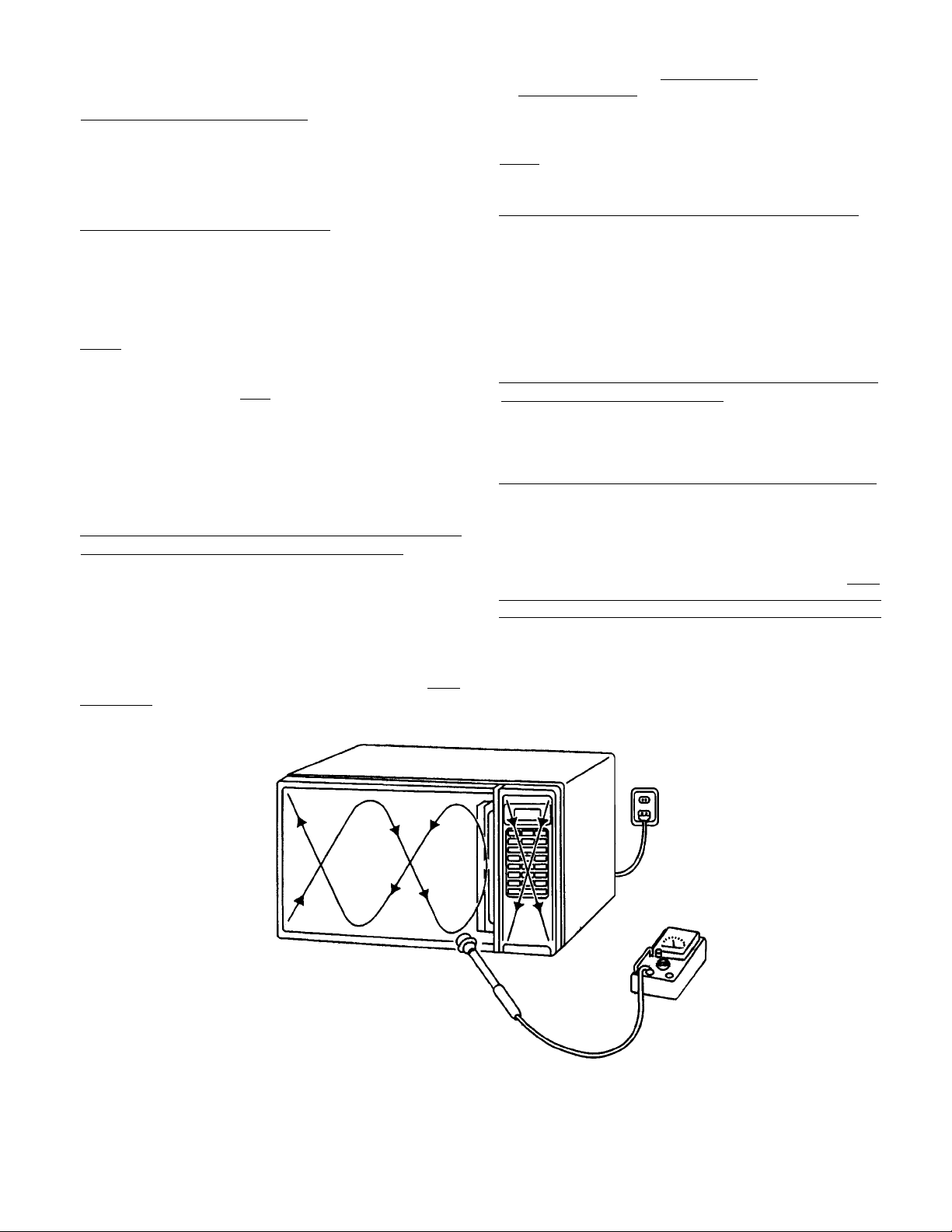
In the area emitting the highest reading, switch the meter
to SLOW RESPONSE, and take a reading for minimum of
three (3) seconds. We recommended the pattern outline
shown below when the door surface is surveyed.
On every service calls, check for microwave
energy emission, must be made according to
the following manner.
Measurement of energy emission
Measurement must be made with the microwave oven
operating at its maximum output and containing a load of
275±15 milliliters of tap water initially at 20o±5o celsius (68
±9oF) placed within the cavity at the center.
NOTE : The water container must be a 600 milliliter beaker
and made of an electrically none conductive
material such as glass or plastic.
The cook tray must be in place when measuring
emission.
A properly operating door and seal assembly will normally
register emission on greater than 4mW/cm
measurement uncertainty with the cooking shelf or tray in
place.
2
to allow for
All repairs must be performed in such a manner
that microwave energy emission are minimal.
Follow the instructions supplied with a detector being used
and performed an R.F. emission test around the door front
and edges and all edges and vent of the outer case. The
cabinet (wrapper) must be in place and the oven fully
assembled.
When performing emission survey, with the meter on FAST
RESPONSE the movement of a detector probe shall not
exceed one (1) inch per second.
NOTE : Periodically check to be sure that the probe tip is
not worn or dirty.
The following U.S. standard applies to microwave ovens :
21 CFR 1030.10, Performance Standard for Microwave
Ovens.
It requires that the power density of the microwave
radiation emitted by a microwave oven shall not exceed
five (5) milliwatts per square centimeter at any point 5
centimeter (about 2 inches) or more from the external
surface of the oven.
All microwave ovens exceeding the emission level of
4mW/cm
microwave ovens and the manufacturer immediately and
the owner should be told not to use the microwave oven
until it has been repaired completely.
If a microwave oven is found to operate with the door open,
report to Dept. of Service, the manufacturer and CDRH*
immediately. Also tell the owner not to use the oven.
*CDRH : Center for Device and Radiological Health.
The Interlock Monitor Switch acts as the final safety switch
protecting the customer from microwave radiation. If the
Interlock Monitor Switch operates to blow the Fuse with
interlocks failed, you must replace all Interlock Switches
Primary and Secondary Interlock Switches and the Monitor
Switch with new ones because the contacts of those
Interlock Switches may be melted and welded together.
2
must be reported to Dept. of Service for
Page 3
- TABLE OF CONTENTS -
Adjustment Procedures ......................................... 1
Specifications ....................................................... 2
Power Output Measurement .................................. 2
Precautions and Repair Service Tips ........................ 2
1.ADJUSTMENT PROCEDURES
TO AVOID POSSIBLE EXPOSURE TO MICROWAVE
ENERGY LEAKAGE, THE FOLLOWING
ADJUSTMENT OF THE INTERLOCK SWITCHES
SHOULD BE MADE ONLY BY AUTHORIZED
SERVICE PERSONNEL.
The SANYO service center should have the designated
detector to measure the microwave energy leakage
after the repair or adjustment.
NOTE : Detector to be used at the service center is
NARDA 8100, 8200 or the equivalent.
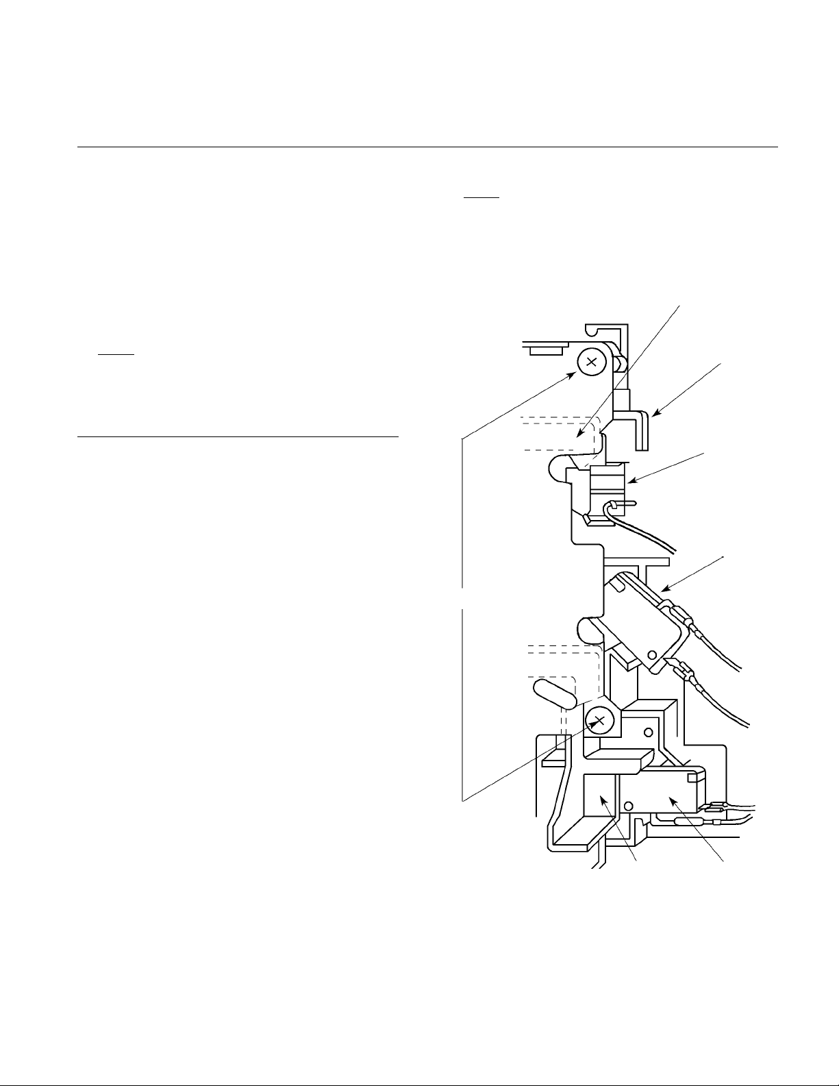
PRIMARY INTERLOCK SWITCH, INTERLOCK
MONITOR SWITCH AND DOOR SENSING SWITCH
ADJUSTMENT
(Figure 1)
(1) Loosen 2 screws securing the Lever Stopper.
(2) Adjust the Lever Stopper position so that it is pushed
forward and pull backward until there is about zero
gap between the Latch Lever and the switch body on
the Primary Interlock Switch and at the same time
there is about zero gap between the Door Latch and
the switch body on the Door Sensing Switch when
the Door Latch is securely locked.
(3) Tighten the Lever Stopper screws securely.
(4) Make sure the Interlock Monitor Switch closes after
the Primary Interlock Switch opens when the door
is opened very slowly, according to “CHECKOUT
PROCEDURE FOR SWITCHES” on page 6.
(5) Make sure the Interlock Monitor Switch opens before
the Primary Interlock Switch closes when the door is
closed very slowly, according to “CHECKOUT
PROCEDURE FOR SWITCHES” on page 6.
(6) Make sure the microwave energy leakage should be
no greater than 4mW/cm2 to allow for measurement
uncertainty when measured with a detector.
Circuit Diagram ............................................. 3
Test Procedures and Troubleshooting............... 4 ~ 7
Disassembly Instructions ................................ 8 ~ 10
Exploded View and Parts List .......................... 11 ~ 14
NOTE
Screws
: If the Interlock Monitor Circuit operates and
at the same time the fuse blows with the
door opened, be sure to replace the
Door Sensing Switch and the electric
circuit related on the Door Sensing Switch,
which act as Secondary Interlock Switch.
Door
Latch
Lever Stopper
Door
Sensing
Switch
Interlock
Monitor
Switch
(All service adjustments must be made for
minimum microwave energy leakage readings.)
- 1 -
Figure 1
Latch
Lever
Primary
Interlock
Switch
Page 4

2. SPECIFICATIONS
Rated Power Consumption .. 920W.
Microwave Output .............. 600W.
Frequency .......................... 2,450MHz±50MHz.
Power Supply ..................... 120V±12V, 60Hz.
Rated Current ..................... 8 Amp.
Safety Devices ................... Thermal Fuse open at 332°F
(167°C) for Cavity.
Thermal Protector open
at 252°F (122°C) for
Magnetron.
Fuse (Cartridge Type 15A)
Primary Interlock Switch,
Door Sensing Switch and
Interlock Monitor Switch.
Timer ................................ 60Mins.
Overall Dimensions ............... 18
Oven Cavity Size ................ 113/4”(W)x121/4”(D)x71/2”(H)
Turn Table Diameter ............ 107/8”
Effective Capacity of
Oven Cavity ....................... 0.7 Cubic Feet.
Net Weight ........................ Approx. 23 Lbs.
1
/16”(W)x1 33/4”(D)x913/16”(H)
3. POWER OUTPUT MEASUREMENT
NOTE
The Power Output specification, 600W. on this model is
measured with IEC measurement. The Power Output is
measured with two (2) liters water is equivalent to 600W.
in measurement with IEC, when measured with the
following Power Output.
(1) Fill two beakers (glass or plastic) with each one liter
of tap water (about 20°C) and measure the water
temperature.
(Use a thermometer with a 1/10 degree gauge).
(2) Place the beakers side by side in the center of the
glass tray.
(3) (a) Set the Timer at any position more than 2 minutes.
(b) Heat the water correctly for 2 minutes.
(4) Take the beakers out, immediately stir the water and
measure the water temperature respectively.
(5) Calculate the temperature rise of water in each beaker.
Then calculate the average value of two temperature
rises.
Output power can be calculated by the equation :
Power Output (W) = 70 x ∆t
Where ∆t is an average temperature rise in degrees
Centigrade.
(6) Power Output shall be in the following range :
Average Temperature Rise Power Output
Minimum : 13.9°F (7.7°C) 540W.
Maximum : 16.9°F (9.4°C) 660W.
(7) Power Output is affected by the line voltage under
load. For correct Power Output measurement, the
line voltage under load must be 120±1 volts.
4. PRECAUTIONS AND REPAIR SERVICE TIPS
PRELIMINARY
A. SINCE NEARLY 2,000 VOLTS EXISTS IN SOME
CIRCUITS OF THIS MICROWAVE OVEN, REPAIRS
SHOULD BE CARRIED OUT WITH GREAT CARE.
B. TO AVOID POSSIBLE EXPOSURE TO MICROWAVE
ENERGY LEAKAGE, THE FOLLOWING PRECAUTIONS
MUST BE TAKEN BEFORE SERVICING.
(1) Before the power is applied :
(a) Open and close door several times to make sure the
Primary Interlock Switch, the Interlock Monitor Switch
and the Door Sensing Switch operate properly.
(Listen for the clicking sound from the switches).
Make sure the Interlock Monitor Switch closes after
the Primary Interlock Switch is opens when the door
is opened. (See pages 1 and 6).
(b) Make sure the perforated screen and the Choke
Dielectric of the door are correctly mounted.
(2) After the power is applied :
(a) Open and close the door to see if the interlock
mechanism operates properly.
(b) Check microwave energy leakage with a leakage
detector and confirm the energy leakage should be
no greater than 4mW/cm2 to allow for measurement
uncertainty.
(3) Do not operate the unit until it is completely repaired,
if any of the following conditions exists :
(a) Door does not close firmly against the cavity front.
(b) The hinge is broken.
(c) The Choke Dielectric or the door seal is damaged.
(d) The door is bent or warped, or there is any other
visible damage to the oven that may cause
microwave energy leakage.
NOTE : Always keep the seal clean.
(e) Make sure that there are no defective parts in the
interlock mechanism.
(f) Make sure there are no defective parts in the
microwave generating and transmission assembly.
(especially waveguide).
(4) The following items should be checked after the unit
is repaired :
(a) The Interlock Monitor Switch is connected correctly
and firmly.
(b) The magnetron gasket on the Magnetron is properly
positioned.
(c) Waveguide and Oven Cavity are intact (no leakage
of microwave energy).
(d) The door can be properly closed and the safety
switches work properly.
(e) The oven must be stopped when the door is opened
or the time is up.
The oven must not be operated with any of the
above components removed or bypassed.
- 2 -
Page 5
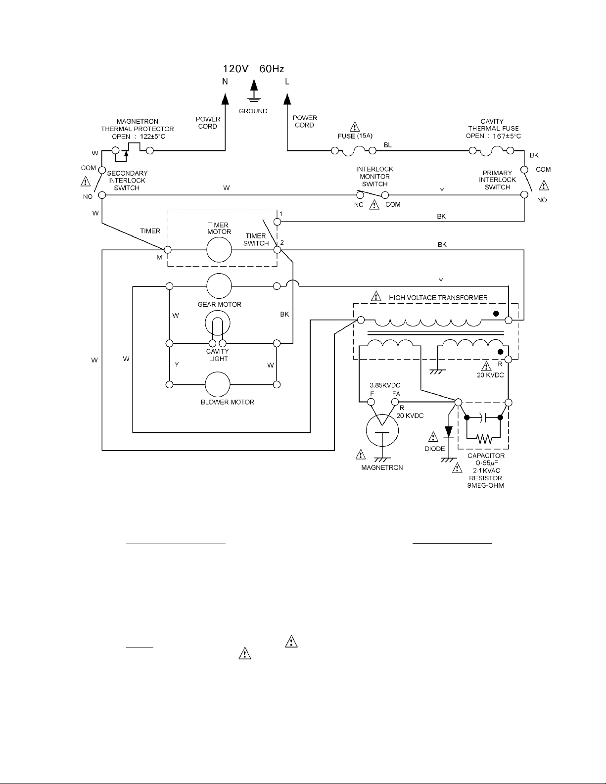
5. CIRCUIT DIAGRAM
Figure 2
CONDITION OF OVEN
TIMER : OFF
DOOR : OPEN
PRIMARY INTERLOCK SWITCH :
LOWER DOOR INTERLOCK SWITCH
SECONDARY INTERLOCK SWITCH:
UPPER DOOR INTERLOCK SWITCH
WIRING COLOUR
BK : BLACK
BL : BLUE
W : WHITE
Y : YELLOW
R : RED
NOTE : The parts marked with have special characteristics of safety,
if replace the marked parts, use only SANYO specified parts.
- 3 -
Page 6

6. TEST PROCEDURES AND TROUBLESHOOTING
CAUTION
- DISCONNECT THE POWER SUPPLY CORD FROM
THE WALL OUTLET WHENEVER REMOVING THE
CABINET FROM THE UNIT. PROCEED WITH THE
TESTS ONLY AFTER DISCHARGING THE HIGH
VOLTAGE CAPACITOR AND REMOVING THE LEAD
WIRES FROM THE PRIMARY WINDING OF THE
HIGH VOLTAGE TRANSFORMER. (SEE FIGURE 3)
A. TEST PROCEDURES
COMPONENT CHECKOUT PROCEDURE RESULT
1) Check for resistance : Across the filament Normal reading :
terminals of the Magnetron with an Less than 1 Ohm.
Ohm-Meter on R x 1 scale.
Ohm-Meter
Secondary
Windings
Filament Windings
Primary
Windings
Figure 3
MAGNETRON
HIGH-VOLTAGE
TRANSFORMER
Figure 4
2) Check for resistance : Between each Normal reading :
filament terminal of the Magnetron and Infinite Ohms.
the chassis ground with an Ohm-Meter
on highest scale.
Ohm-Meter
Figure 5
1) Measure the resistance : Normal readings :
With an Ohm-Meter on R x 1 scale.
a . Primary winding : Approximately 0.75 Ohms.
b . Filament winding : Less than 1 Ohm.
c . Secondary winding : Approximately 167.5 Ohms.
2) Measure the resistance : Normal readings :
With an Ohm-Meter on highest scale.
a . Primary winding to ground : Infinite Ohms.
b . Filament winding to ground : Infinite Ohms.
Ohm-Meter
NOTE : Remove varnish of
measured point.
Figure 6
- 4 -
Page 7

COMPONENT CHECKOUT PROCEDURE RESULT
Measure the resistance : Across two terminals Normal reading :
with an Ohm-Meter on highest scale. Momentarily indicates several Ohms,
and gradually returns to 10 Meg-Ohms.
HIGH-VOLTAGE Abnormal reading :
CAPACITOR Indicates continuity or 10 Meg-Ohms
including from the beginning.
BLEEDER
RESISTOR
Ohm-Meter
Figure 7
Measure the resistance : Across two terminals Normal reading :
with an Ohm-Meter on R x 10,000 scale. Indicates about the middle position in
one direction (forward direction) and
Ohm-Meter
infinite Ohms in the reverse direction,
using meter which is provided with a
9 volt battery.
HIGH-VOLTAGE
DIODE NOTE
Figure 8
--Some digital meter may show over
even in a forward direction because
low measuring voltage of meter does
not allow the meter current to pass
through the High Voltage Diode.
Abnormal reading :
Indicates continuity or infinite Ohms
in both directions.
- 5 -
Page 8

CHECKOUT PROCEDURE FOR SWITCHES
Disconnect the lead wires from the switches and check for the continuity of the switches, connecting an
Ohm-Meter to its terminals.
SWITCHES CHECKOUT PROCEDURES DOOR OPEN DOOR CLOSED
Primary Interlock
Secondary Interlock
Interlock Monitor
Connect an Ohm-Meter leads to terminals
“COM” and “NO” of Switch.
Connect an Ohm-Meter leads to terminals
“COM” and “NC” of Switch.
CAUTION : After checking the switches, make sure that the Interlock Monitor Switch is properly connected
according to the CIRCUIT DIAGRAM on page 3.
B. TROUBLE SHOOTING
CONDITION TROUBLE CHECK RESULT REMEDY
Power is applied
with normal
voltage.
Timer is set
and close the
door.
Cavity Lamp
does not light
but oven
operates.
Cavity Lamp
does not light
and oven also
does not operate.
Cavity Lamp. Broken Lamp.
Primary Interlock
Switch
(See page 6)
Fuse (15A)
No continuity.
Blown Fuse.
Replace.
Replace
(See page 1)
Replace.
Oven does not
operate but
Cavity Lamp
lights.
Timer Switch.
Thermal
Protector
for Cavity.
Thermal
Protector
for Magnetron.
Secondary
Interlock Switch
(See page 6)
Power Control
Switch.
H.V.Transformer
(See page 4)
H.V.Capacitor
or H.V.Diode
(See page 5)
Magnetron
(See page 4)
No continuity.
No continuity.
No continuity.
No continuity.
No continuity.
Resistance
incorrect.
Resistance
incorrect.
Resistance
incorrect.
Replace Timer.
Replace.
Replace.
Replace
(See page 1)
Replace Timer.
Replace.
Replace.
Replace
(See page 9)
- 6 -
Page 9

CONDITION TROUBLE CHECK RESULT REMEDY
Fuse (15A)
blows
off immediately.
(See page 9)
Oven operates
for a few minutes
and stops.
Oven operates
and does not
stops.
Output Power is
low when 600W
is selected.
Timer
Motor.
Blower Motor.
Secondary Circuit
(High Voltage)
Gear Motor.
Blower Motor.
Timer
Motor.
Magnetron
(See page 4)
H.V.Capacitor
(See page 5)
Shorted.
Shorted.
Shorted.
Shorted.
No operation.
No continuity
of coil.
Poor oscillation.
Poor function.
Replace Timer.
Replace.
Replace.
Replace.
Replace.
Replace Timer.
Replace
(See page 9)
Replace.
Output Power is
high level when
low is selected.
Uneven heating.
Power Control
Switch.
Gear Motor.
- 7 -
Contact on.
No operation.
Replace Timer.
Replace.
Page 10

7. DISASSEMBLY INSTRUCTIONS
• OVEN MUST BE DISCONNECTED FROM ELECTRICAL
OUTLET WHEN MAKING REPLACEMENTS, REPAIRS,
ADJUSTMENTS AND CONTINUITY CHECKS BEFORE
PROCEEDING WITH ANY REPAIR WORK. AFTER
DISCONNECTING, WAIT AT LEAST 1 MINUTE, UNTIL
THE CAPACITOR IN THE HIGH-VOLTAGE AREA
HAS FULLY DISCHARGED.
• WHEN REPLACING ANY DOOR MICROSWITCH,
REPLACE WITH THE SAME TYPE SWITCH SPECIFIED
ON THE PARTS LIST.
A. REMOVING DOOR SENSING SWITCH
(Figure 1 on page 1, 9-a)
(1) Disconnect all wire leads from the Door Sensing
Switch. (Figure 1 on page 1)
(2) Remove 2 screws securing the Lever Stopper.
(3) Push the Door Sensing Switch upward while pressing
adjacent Upper Switch Stopper of Lever Stopper and
Lower Switch Stopper down (Figure 9-a).
(4) Then remove it by lightly pressing the switch toward
you (Figure 9-a).
B. REMOVING PRIMARY INTERLOCK SWITCH AND
INTERLOCK MONITOR SWITCH
(Figure 9-b)
(1) Disconnect all wire leads from Primary Interlock
and Interlock Monitor Switch.
(2) Pull the Primary Interlock Switch upward at
the same time while pushing the Switch
Stoppers to allow a space between the switch
body and catches.
(3) Press down the Switch Stopper “A” and at the
same time push Interlock Monitor Switch towards
the right.
(4) Make necessary adjustments or replacement
of switch by the reversing step (2) or (3) and
check microwave energy leakage according to
“1. ADJUSTMENT PROCEDURES” on page 1,
after it is replaced with new one, and check
proper operation of it according to
“CHECKOUT PROCEDURE FOR SWITCHES”
on page 6.
Switch Stoppers
(5) Make necessary adjustments or replacements of the
Door Sensing Switch by reversing step (3) and check
microwave energy leakage according to
“1. ADJUSTMENT PROCEDURES” on page 1,
after it is replaced with new one, and check proper
operation of it according to “CHECKOUT
PROCEDURE FOR SWITCHES” on page 6.
Door
Sensing
Switch
Lower
Switch
Stopper
Figure 9-a
Upper
Switch
Stopper
Switch Stoppers
“A”
Interlock
Monitor
Switch
Primary
Interlock
Switch
Switch Stoppers
Figure 9-b
Interlock Switch Replacement - when replacing
faulty switches, be sure switch mounting tabs
are not bent, broken or otherwise deficient in
their ability to secure the switches in place.
- 8 -
Page 11

C. REMOVING BLOWER MOTOR
(Figures 10 (Top View) and 11).
(1)Disconnect all lead wires from the Blower
Motor and H.V. Capacitor.
(2) Remove 3 screws securing the Blower Base
and Blower Motor from Cavity Rear Plate
(Figure 11).
D. REMOVING MAGNETRON
(Figure 10 (Top View))
(1) Remove Duct (mag. exhaust). By removing
a screw securing the stay.
(2) Disconnect 2 lead wires from the Magnetron.
(3) Remove 3 screws securing the Magnetron to
the Waveguide.
(4) Take out Magnetron VERY CAREFULLY.
NOTE
1.When removing the Magnetron from the Cavity or
Waveguide, use a proper care so that the dome of
the Magnetron does not hit any adjacent parts of
Microwave Oven.
2.Make sure that the contact face of the Magnetron
Gasket is free from any damage or deformation.
3.Adjust the position of the Magnetron properly, so
that it correctly sits in place and the Magnetron
Gasket is in contact with the mounting rim evenly.
4.While holding the Magnetron under this condition,
tighten mounting screws or nuts with your fingers
temporarily.
5.Further tighten the screws or nuts with a box
wrench, giving one or two turns to each of the
screws (or nuts) alternatively so that the
Magnetron is mounted onto the bracket uniformly.
6.After replacing the Magnetron, be sure to check
the microwave energy leakage with a leakage
detector and confirm the energy leakage should
be no greater than 4mW/cm
measurement uncertainty.
2
to allow for
Duct (mag. exhaust)
Stay
Screws
Blower
Base
Blower
Fan
Blower
Motor
Blower
Base
Thermostat
Figure 10 (Top View)
Fuse
E. REMOVING FUSE
Remove the 15A. Fuse with a screwdriver.
NOTE
-- When replacing the 15A. Fuse, be sure to use an
exact repair part.
-- If the 15A. Fuse blows immediately, check the
Primary Interlock Switch, and the Interlock Monitor
Switch, according to “CHECKOUT PROCEDURE
FOR SWITCHES” on page 6, and make sure to
check the microwave energy leakage according to
“1. ADJUSTMENT PROCEDURES” on page 1,
when the Primary Interlock Switch or the Interlock
Monitor Switch is adjusted or replaced.
Figure 11
-- If the Primary Interlock Switch is defective, replace not
only the Primary Interlock Switch but also the Interlock
Monitor Switch. Then install a new 15A. Fuse.
-- If the Primary Interlock Switch and the Interlock Monitor
Switch operate properly, determine which of the following
is defective: Blower Motor, Turntable Motor, High Voltage
Transformer, High Voltage Capacitor, High Voltage Diode
or Magnetron.
- 9 -
Page 12

F. REMOVING DOOR
(1) Remove 2 hex nuts securing the upper hinge.
(2) Tilt the top of the Door toward you.
(3) Lift up the Door to remove it.
NOTE
-- After replacing the Door, be sure to check that
the Primary Interlock Switch, the Door Sensing
Switch and the Interlock Monitor Switch operate
normally. (See page 1).
-- After replacing the Door, check for microwave
energy leakage with a leakage detector.
Microwave energy leakage should be no greater
than 4mW/cm2 to allow for measurement
uncertainty.
G. DISASSEMBLING DOOR
(Figure 12)
(1) Insert a thin flat-blade screwdriver between
the Choke Dielectric and the Door Main Frame
and lift up the Choke Dielectric to release
hooks one by one. (Figure 12).
(2) Remove the Choke Dielectric.
(3) To detach the Door Cover, insert a thin flat-blade
screwdriver between Door Cover and Door Panel
and release the projections inside Door Cover.
(4) To detach the Door Panel, insert a thin flat-blade
screwdriver between the Door Cover and Door
Main Frame.
Hooks
H. REMOVING CAVITY COVER
(Figure 13)
(1) Gently press both ends to release 3 hooks,
while holding the Cavity Cover from the
inside of oven.
(2) Pull out the Cavity Cover.
Cavity Cover
Press
Press
Figure 13
I. REMOVING TURNTABLE MOTOR COVER
(Figure 14)
(1) Turn over the oven on its back.
(2) Cut the 6-joints of the Bottom Plate using
diagonal pliers (nipper).
(3) Separate the Motor Cover from Bottom Plate.
(4) Remove 2 screws securing Turntable Motor
to the Cavity and take it out.
Hooks
Door
Main
Frame
Choke
Dielectric
Hooks
Figure 12
NOTE
-- The Choke Dielectric may be damaged
when it is removed. When reinstalling
it replace it with new ones if it is damaged.
-- After installing the Door in place, check for
microwave energy leakage with a detector.
Microwave energy leakage should be no
greater than 4mW/cm2 to allow for
measurement uncertainty.
Hooks
- 10 -
NOTE : Bent the cut joints inside slightly for
safety and be careful of sharp edge.
6 Joints
Motor Cover
Bottom Plate
Figure 14
Page 13

8. EXPLODED VIEW AND PARTS LIST
CAVITY PARTS
*** ALL SERVICE ON MICROWAVE OVENS SHOULD BE PERFORMED BY A QUALIFIED TECHNICIAN USING
APPROVED TESTING EQUIPMENT. CUSTOMERS SHOULD NOT ATTEMPT TO REPLACE PARTS IDENTIFIED
BY A TRIPLE ASTERISK (***).
Key
Part No. Description Q’ty
No.
1 617 228 9755 Cabinet (F1010MWFC) 1
1 617 245 1503 Cabinet (F1010MBFC) 1
2 411 082 5201 SCR TPG TRS 4 x 10 Z1 5
3 411 160 6007 SCR TPG TRS + SRT 4 x 10 Z1 3
4 617 216 8906 Power Cord 1
5 411 160 6106 SCR S-T TRS + SRT 4 x 10 Z1 1
6 617 228 8918 Oven Cavity*** (Not Service Part) 1
7 617 124 1068 Gear Motor 1
8 411 010 5808 SCR EVR PAN 4 x 10 Z1 2
9 617 177 8656 Bottom Plate*** (Not Service Part) 1
10 617 221 6096 Plastic Foot with Canoe Clip 4
11 411 011 0802 Bolt Hex+SW+W 5 x 14 Z1*** 2
12 617 180 6137 Hinge, Lower*** 1
Key
Part No. Description Q’ty
No.
13
14
15 617 220 9401 Turn Table Shaft 1
16 617 178 5562 Roller Base Assy 1
17 617 200 0657 Rotating Tray 1
18
19 617 236 6609 Cavity Cover 1
20
21 411 006 6604 SCR TPG PAN 3 x 6 Z1 1
22 617 244 7377 Thermal Fuse 169°C 1
23 617 080 5315 Special Washer 1
24
25
26 617 229 9013 Special Screw 2
- 11 -
Page 14

SWITCHES AND MICROWAVE PARTS
NOTE : The parts marked with have special characteristics
of safety, if replace the marked parts, use only SANYO
specified parts.
*** ALL SERVICE ON MICROWAVE OVENS SHOULD BE PERFORMED BY A QUALIFIED TECHNICIAN USING
APPROVED TESTING EQUIPMENT. CUSTOMERS SHOULD NOT ATTEMPT TO REPLACE PARTS IDENTIFIED
BY A TRIPLE ASTERISK (***).
Key
Part No. Description Q’ty
No.
1 411 082 5201 SCR TPG TRS 4 x 10 Z1 6
2 617 245 0872 H.V. Transformer,***YS-F1010 1
3 617 177 8694 Stay, Cavity & Magnetron 1
4 411 006 6604 SCR TPG PAN 3 x 6 Z1 1
5 617 125 9650 Thermostat, Magnetron 122oC1
6 415 003 0009 Magnetron,*** 2M232J(M)6 1
7 423 014 2509 Fuse, 250V 15A 1
8 617 137 8269 Fuse Holder 1
9 617 179 2492 Lead Wire Ass’y (including Diode) 1
10 617 177 8717 Blower Base 1
11 617 237 2556 H.V. Capacitor including Resistor, 1
12 617 077 5830 Capacitor Band 1
13 411 011 5609 Bolt Hex 4 x 10 Z1 3
14 617 236 0065 Duct, Mag. Exhaust 1
15 617 005 5147 Lamp, 120V 20W 1
16 617 236 6715 Lamp Socket 1
0.65uf 2.1KV
Key
Part No. Description Q’ty
No.
17 617 197 7417 Blower Motor 1
18 412 010 8301 SCR TPG TRS 4 x 10 E 2
19 617 196 8507 Blower Fan 1
20 617 245 6256 Latch Lever*** 1
21 617 232 3299 Micro Switch,*** Primary Interlock 1
22 617 232 3305 Micro Switch,*** Interlock Monitor 1
23 617 232 3299 Micro Switch,*** Door Sensing 1
24
25 617 245 6096 Lever Stopper*** 1
26 411 102 5907 SCR ETG TRS 4 x 10 N2 3
27 411 129 5805 SCR TPG BIN 3 x 10 Z1 1
28
29 617 124 3796 Lead Wire Ass’y 1
SZMV16FD63
SZMV16FD62
SZMV16FD63
- 12 -
Page 15

DOOR PARTS
*** ALL SERVICE ON MICROWAVE OVENS SHOULD BE PERFORMED BY A QUALIFIED TECHNICIAN USING
APPROVED TESTING EQUIPMENT. CUSTOMERS SHOULD NOT ATTEMPT TO REPLACE PARTS IDENTIFIED
BY A TRIPLE ASTERISK (***).
Key
Part No. Description Q’ty
No.
1 617 245 1619 Door Cover***(F1010MWFC) 1
1 617 186 0320 Door Cover***(F1010MBFC) 1
2 617 178 5340 Door Panel*** 1
3 617 228 8710 Door Main Frame*** (F1010MWFC) 1
3 617 202 8354 Door Main Frame*** (F1010MBFC) 1
(Also order Door Sheet when
replacing Door Main Frame)
(Also order Door Sheet when
replacing Door Main Frame)
Key
Part No
No.
4 617 178 0062 Choke Dielectric*** 1
5 617 234 7509 Door Sheet 1
6 411 054 1903 Nut Hex + Flg W / SRT 5*** 2
7 617 180 6151 Hinge, Upper*** 1
8 411 011 0802 Bolt Hex+SW+W 5 x 14 Z1*** 2
9 617 158 0617 Spring*** 1
10 617 179 2478 Door Latch*** 1
. Description Q’ty
- 13 -
Page 16

CONTROL PANEL PARTS
*** ALL SERVICE ON MICROWAVE OVENS SHOULD BE PERFORMED BY A QUALIFIED TECHNICIAN USING
APPROVED TESTING EQUIPMENT. CUSTOMERS SHOULD NOT ATTEMPT TO REPLACE PARTS IDENTIFIED
BY A TRIPLE ASTERISK (***).
Key
Part No. Description Q’ty
No.
1 617 245 9806 Knob (F1010MWFC) 1
1 617 245 1541 Knob (F1010MBFC) 1
2 411 129 5805 SCR TPG BIN 3 x 10 Z1 3
3 617 245 0858 Control Frame***(F1010MWFC) 1
3 617 245 1558 Control Frame***(F1010MBFC) 1
Key
Part No. Description Q’ty
No.
4 411 160 6205 SCR TPG TRS + SRT 4 x 10 Z1 1
5 617 245 0834 Timer Switch*** 1
6 617 080 9559 Spring, Door Release Lever*** 1
7 617 245 0841 Door Release Lever***(F1010MWFC) 1
7 617 189 1942 Door Release Lever***(F1010MBFC) 1
PRINTED MATTER (Items Not Illustrated)
Key
Part No. Description Q’ty
No.
617 245 0940 Operating Inst. (English / Spanish) 1
617 245 0896 Carton Box Comp. (F1010MWFC) 1
617 245 1572 Carton Box Comp. (F1010MBFC) 1
617 245 0544 Name Plate (F1010MWFC) 1
617 245 1527 Name Plate (F1010MBFC) 1
For Parts or Service Contact
SANYO FISHER SERVICE COMPANY
21605 Plummer Street,
JUNE 2001. 1500 LT Printed in Singapore
- 14 -
Chatsworth, CA91311 U.S.A.
 Loading...