

Page 1
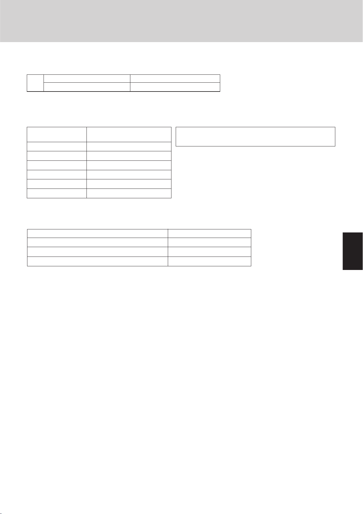
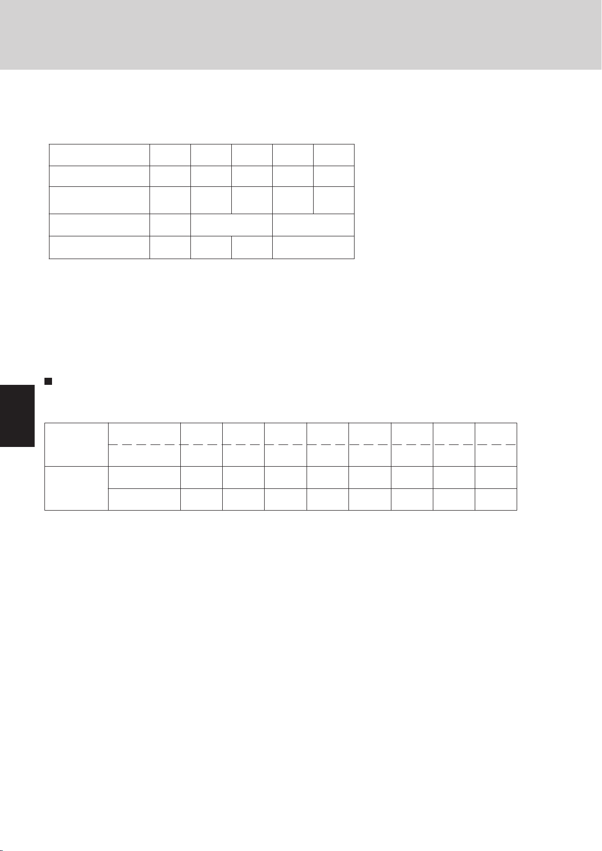
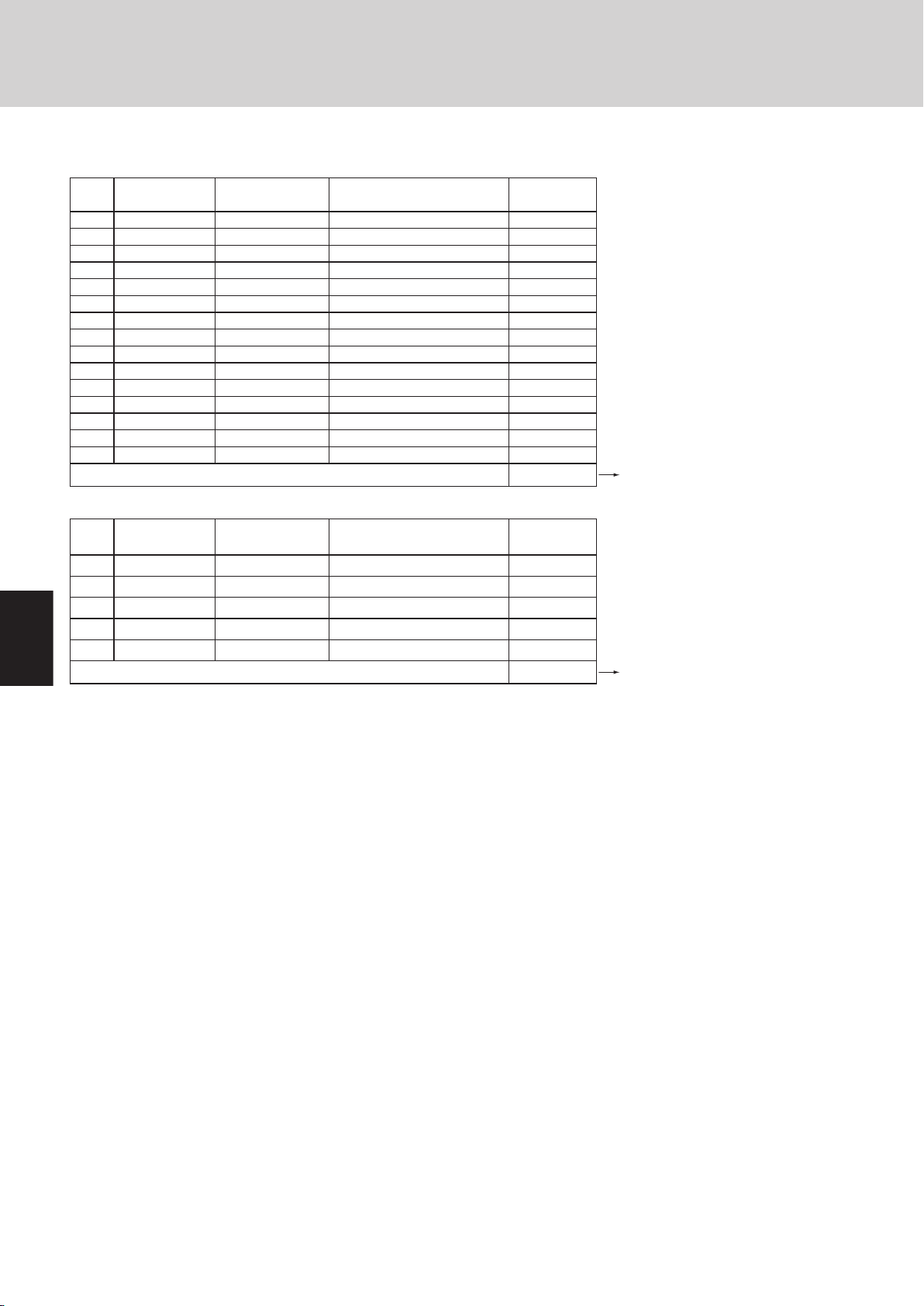
OUTDOOR MODEL No. PRODUCT CODE No. APPLICABLE INDOOR MODEL No. V/ø/Hz
CHDX09053 85403301 AHX,UHX,KHX 0752
CHDX14053 85403302 AHX,KHX 0952 OUTDOOR
XHX,AHX,UHX,THX,KHX 1252 208-230/3ø/60
XHX,UHX,THX,KHX 1852
XHX,UHX,THX,KHX 2452 INDOOR
XHX,UHX,DHX 3652 208-230/1ø/60
DHX 4852
85464869238002
REFERENCE NO.
TD831138-02
Page 2
i
Page 3
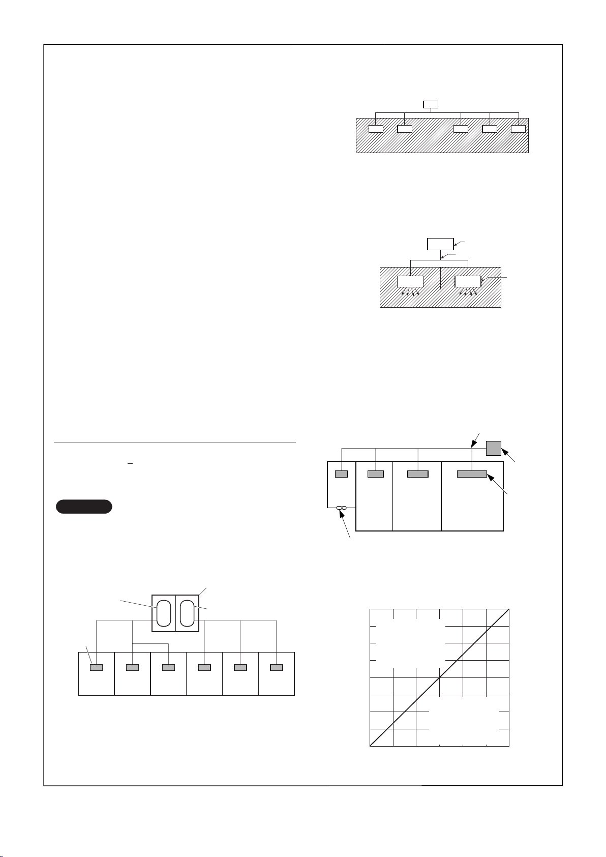
Check of Density Limit
NO TE
Outdoor unit
Refrigerant tubing
Indoor unit
e.g., charged
amount (353 oz)
Outdoor unit
Indoor unit
Room A Room B Room C Room D Room E Room F
e.g., charged
amount (529 oz)
Refrigerant tubing
Outdoor unit
Very
small
room
Indoor unit
Small
room
Medium
room
Large room
Mechanical ventilation device – Gas leak detector
0 0
57
114
170
227
284
341
398
454
0
500
1000
1500
2000
2500
3000
3500
4000
400200 600 800 1000 1200
Total amount of refrigerant
Min. indoor volume
Min. indoor floor area
(when the ceilin
g
is 8.8 ft. hi
g
h)
ft.
3
ft.
2
oz
Range above
the density limit of
0.3 oz/ft.
3
(countermeasures
needed)
Range below
the density limit of
0.3 oz/ft.
3
(countermeasures
not needed)
The room in which the air conditioner is to be
installed requires a design that in the event of refrigerant gas leaking out, its density will not exceed a set
limit.
The refrigerant (R410A), which is used in the air conditioner, is safe, without the toxicity or combustibility of
ammonia, and is not restricted by laws imposed to protect
the ozone layer. However, since it contains more than air,
it poses the risk of suffocation if its density should rise
excessively. Suffocation from leakage of refrigerant is
almost non-existent. With the recent increase in the number of high density buildings, however, the installation of
multi air conditioner systems is on the increase because of
the need for effective use of floor space, individual control,
energy conservation by curtailing heat and carrying power,
etc.
Most importantly, the multi air conditioner system is able
to replenish a large amount of refrigerant compared to
conventional individual air conditioners. If a single unit
of the multi air conditioner system is to be installed in a
small room, select a suitable model and installation procedure so that if the refrigerant accidentally leaks out,
its density does not reach the limit (and in the event of
an emergency, measures can be made before injury can
occur).
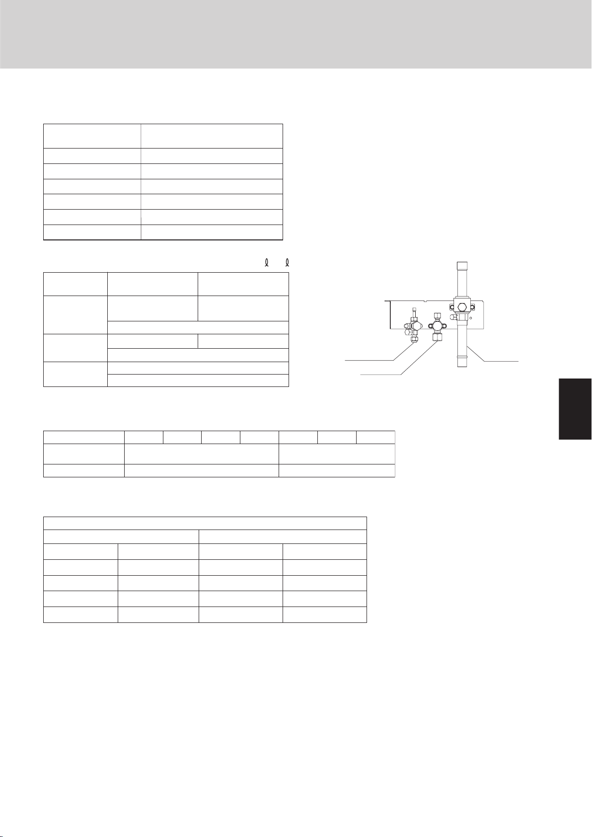
In a room where the density may exceed the limit, create
an opening with adjacent rooms, or install mechanical
ventilation combined with a gas leak detection device.
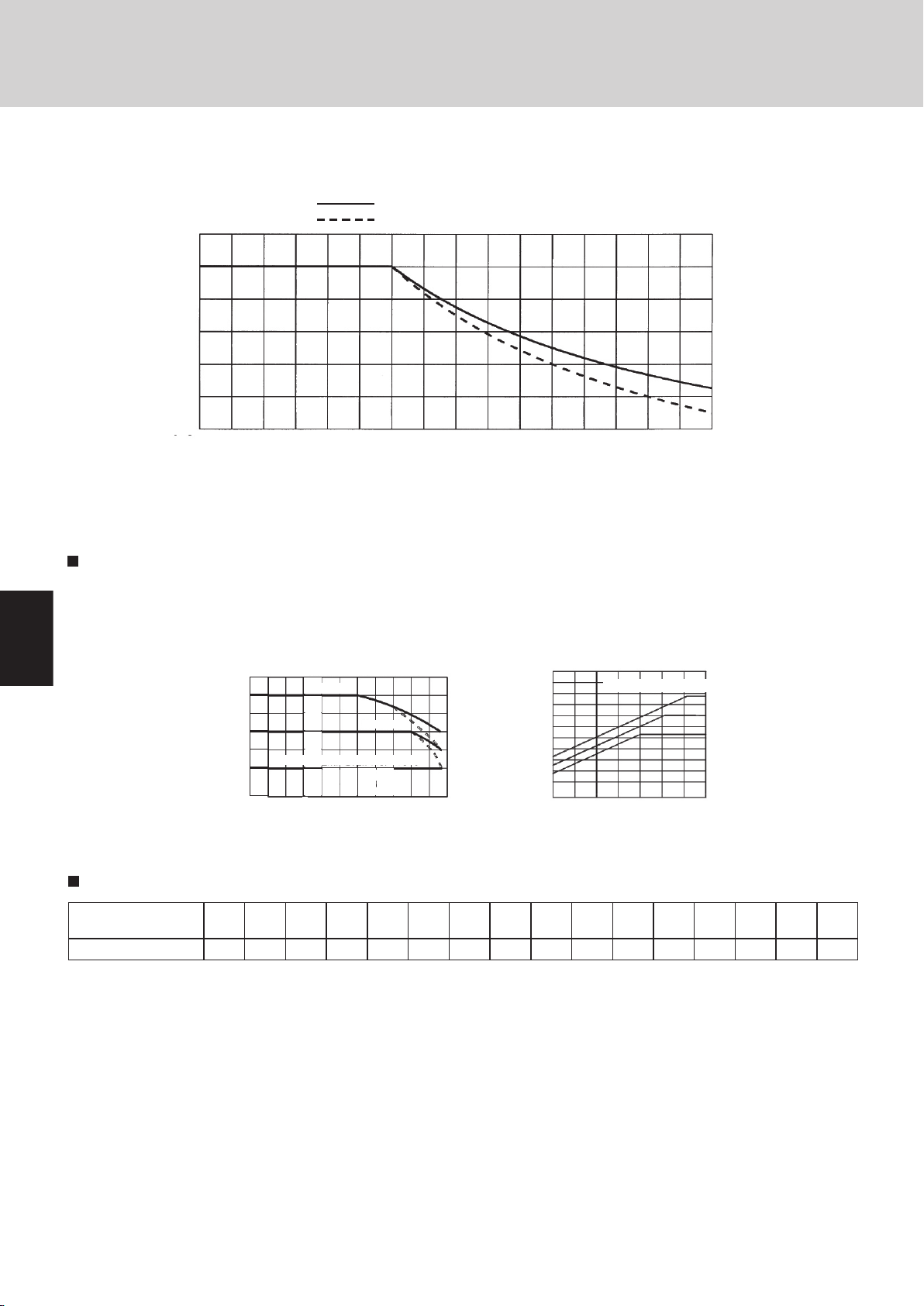
The density is as given below.
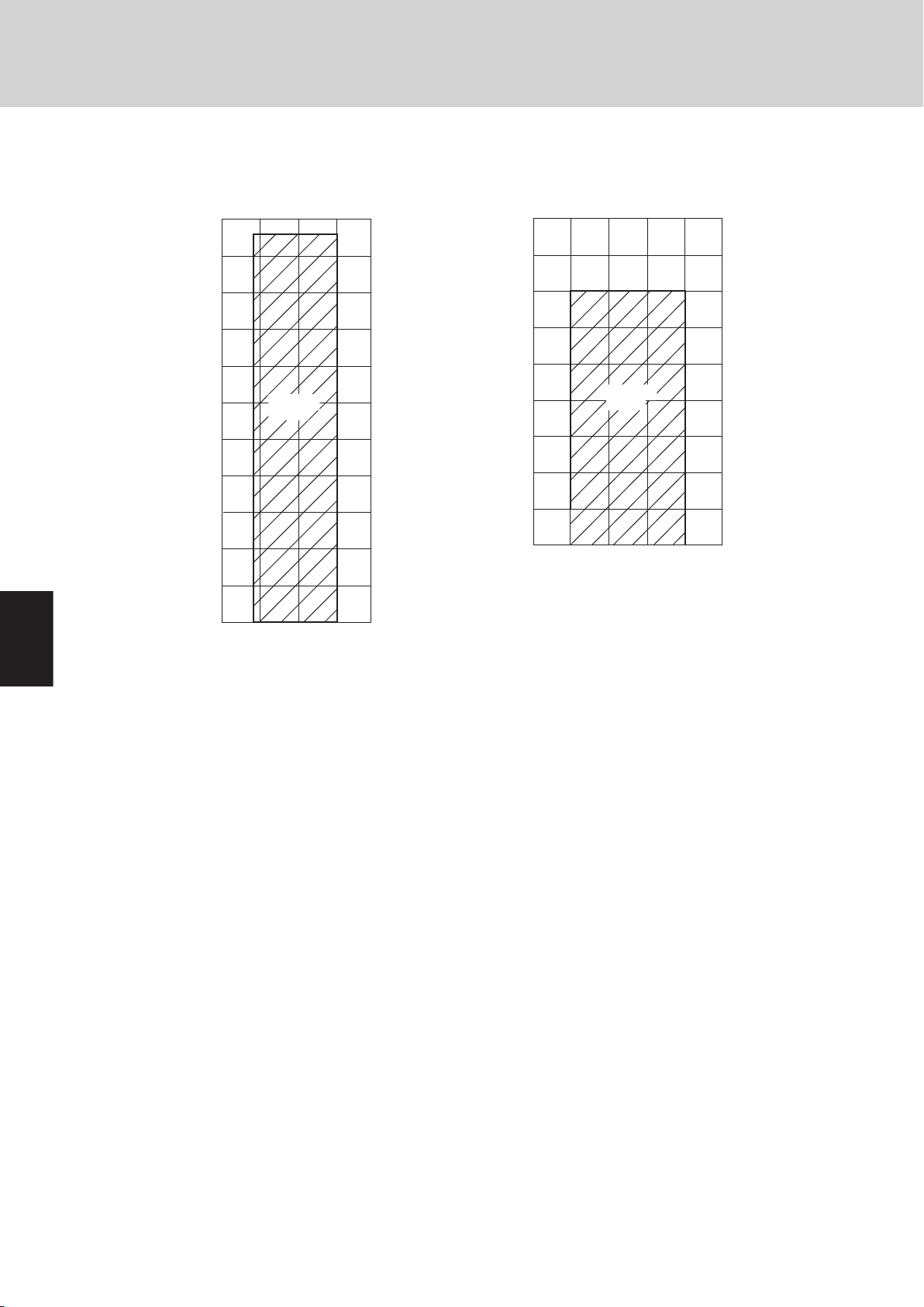
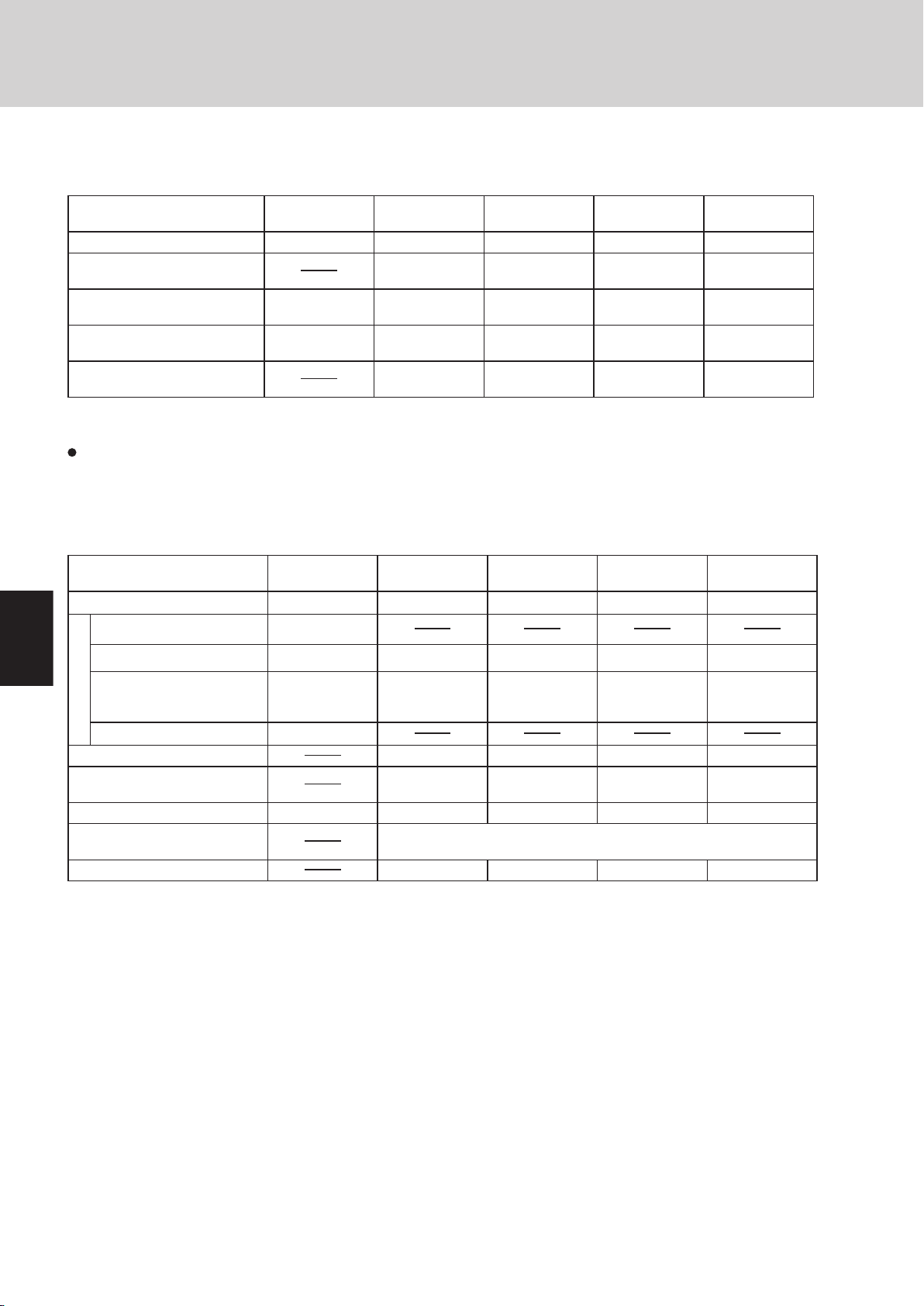
2. The standards for minimum room volume are as follows.
(1) No partition (shaded portion)
(2) When there is an effective opening with the adjacent
room for ventilation of leaking refrigerant gas (opening without a door, or an opening 0.15% or larger
than the respective floor spaces at the top or bottom
of the door).
(3) If an indoor unit is installed in each partitioned room
and the refrigerant tubing is interconnected, the
smallest room of course becomes the object. But
when mechanical ventilation is installed interlocked
with a gas leakage detector in the smallest room
where the density limit is exceeded, the volume of the
next smallest room becomes the object.
Total amount of refrigerant (lbs)
Min. volume of the indoor unit installed room (ft.3)
<
Density limit (oz/ft.3)
The density limit of refrigerant which is used in multi air
conditioners is 0.3 oz/ft.3 (ISO 5149).
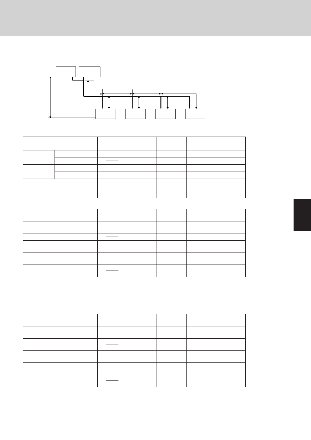
1.If there are 2 or more refrigerating systems in a single
refrigerating device, the amount of refrigerant should be
as charged in each independent device.
For the amount of charge in this example:
The possible amount of leaked refrigerant gas in
rooms A, B and C is 353 oz.
The possible amount of leaked refrigerant gas in
rooms D, E and F is 529 oz.
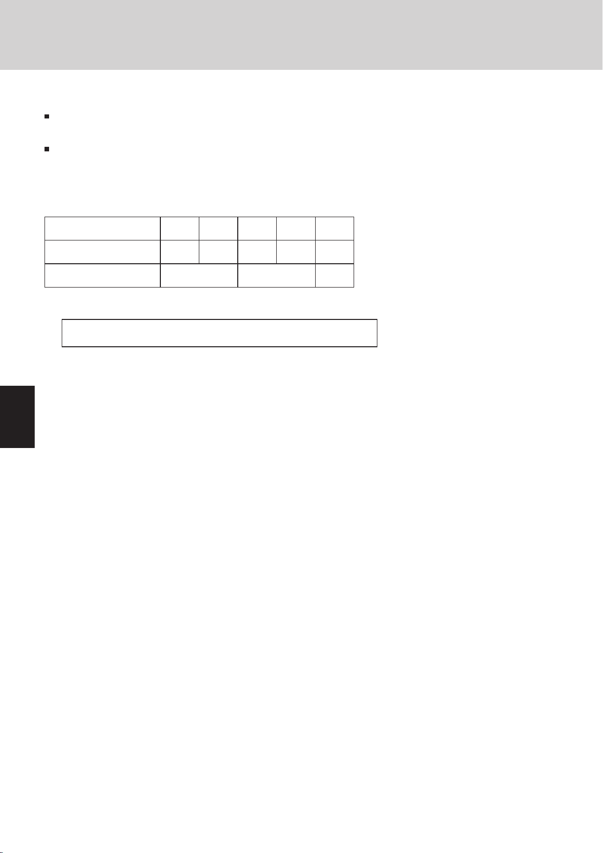
3. The minimum indoor floor space compared with the
amount of refrigerant is roughly as follows: (When the
ceiling is 8.8 ft. high)
ii
Page 4

Contents
Section 1: OUTLINE OF W-2WAY ECO-i SYSTEM ................................................................1-1
1. Line-up .............................................................................................................1-2
2. Features of W-2WAY ECO-i SYSTEM .............................................................1-4
Section 2: DESIGN OF W-2WAY ECO-i SYSTEM ..................................................................2-1
1. Model Selecting and Capacity Calculator ........................................................2-2
2. System Design ...............................................................................................2-17
3. Electrical Wiring .............................................................................................2-23
4. Installation Instructions ..................................................................................2-27
Section 3: Control of W-2WAY ECO-i SYSTEM .....................................................................3-1
1. Main Operating Functions ................................................................................3-3
2. Wireless Remote Controller .............................................................................3-5
3. Timer Remote Controller................................................................................3-22
4. System Controller ..........................................................................................3-38
5. Simplified Remote Controller .........................................................................3-56
6. Remote Sensor ..............................................................................................3-64
Section 4: W-2WAY ECO-i SYSTEM UNIT SPECIFICATIONS ..............................................4-1
1. Outdoor Unit ....................................................................................................4-2
2. 4-Way Air Discharge Semi-concealed Type (X Type) .....................................4-12
3. 1-Way Air Discharge Semi-concealed Type (A Type) .....................................4-24
4. Concealed Duct Type (U Type) .......................................................................4-33
5. Concealed Duct High-Static Pressure Type (D Type) .....................................4-50
6. Ceiling-Mounted Type (T Type) ......................................................................4-57
7. Wall-Mounted Type (K Type) ..........................................................................4-66
Section 5: TEST RUN ..............................................................................................................5-1
1. Preparing for Test Run .....................................................................................5-2
2. Test Run Procedure .........................................................................................5-3
3. Main Outdoor Unit PCB Setting .......................................................................5-4
4. Auto Address Setting .......................................................................................5-6
5. Remote Controller Test Run Settings .............................................................5-12
6. Caution for Pump Down .................................................................................5-13
7. Meaning of Alarm Messages .........................................................................5-14
Section 6: ELECTRICAL DATA ...............................................................................................6-1
1. Outdoor Unit ....................................................................................................6-2
2. Indoor Unit .......................................................................................................6-6
Section 7: PCB AND FUNCTIONS .........................................................................................7-1
1. Outdoor Unit Control PCB ...............................................................................7-2
2. Indoor Unit Control PCB Switches and Functions ...........................................7-6
iii
Page 5

Outline of W-2Way ECO-i SYSTEM
1
2
3
4
5
6
7
8
Contents
1. OUTLINE OF W-2Way ECO-i MULTI SYSTEM
1. Line-up .................................................................................................................................1-2
2. Features of W-2WAY ECO-i SYSTEM .................................................................................1-4
1-1
Page 6
1
2
3
4
5
6
7
8
1
2
3
4
5
6
7
8
1
2
3
4
5
6
7
8
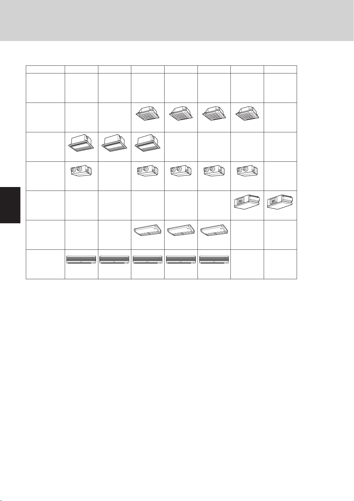
1. Line-up
Capacity: BTU/h
(kW)
Cooling
/
Heating
Type
97 12 18 24 36 48
XHX1252 XHX1852 XHX2452 XHX3652
KHX0952 KHX1252 KHX2452KHX1852
AHX0952 AHX1252
THX1852THX1252 THX2452
UHX0752 UHX1252 UHX1852 UHX2452
DHX4852
Wall-Mounted
Type
(K Type)
Concealed Duct
Type
(U Type)
7,500 (2.2)
8,500 (2.5)
/
9,600 (2.8)
11,000 (3.2)
/
12,000 (3.6)
14,000 (4.2)
/
36,000 (10.6)
39,000(11.4)
/
47,800 (14.0)
54,600(16.0)
/
25,000 (7.3)
27,000(8.0)
/
19,000 (5.6)
21,000(6.3)
/
KHX0752
AHX0752
4-Way Air
Discharge SemiConcealed Type
(X Type)
Ceiling-Mounted
Type
(T Type)
1-Way Air
Discharge SemiConcealed Type
(A Type)
Concealed Duct
High-Static Pressure
Type(D Type)
DHX3652
UHX3652
Indoor units
Outline of W-2Way ECO-i SYSTEM
1-2
Page 7
1
2
3
4
5
6
7
8
1-3
Outline of W-2Way ECO-i SYSTEM
1
2
3
4
5
6
7
8
1. Line-up
Type
Type
90
Capacity: BTU/h (kW)
95,500 (28.0)
Cooling / Heating / 107,500 (31.5)
Outdoor Unit
Capacity: BTU/h (kW)
Cooling / Heating
Outdoor Unit
CHDX14053
CHDX09053
153,600 (45.0)
140
/ 170,600 (50.0)
Air direction
Air direction
2-11/64
8-47/64
13-5/16
18-5/8
4-39/64
2-59/64
6-15/16
31-19/64
65-25/32
(8-1/2)
74-19/64
2-11/64
8-47/64
13-5/16
18-5/8
4-39/64
2-59/64
6-15/16
31-19/64
65-25/32
(8-1/2)
74-19/64
Outdoor units
Page 8
1
2
3
4
5
6
7
8
1
2
3
4
5
6
7
8
1
2
3
4
5
6
7
8
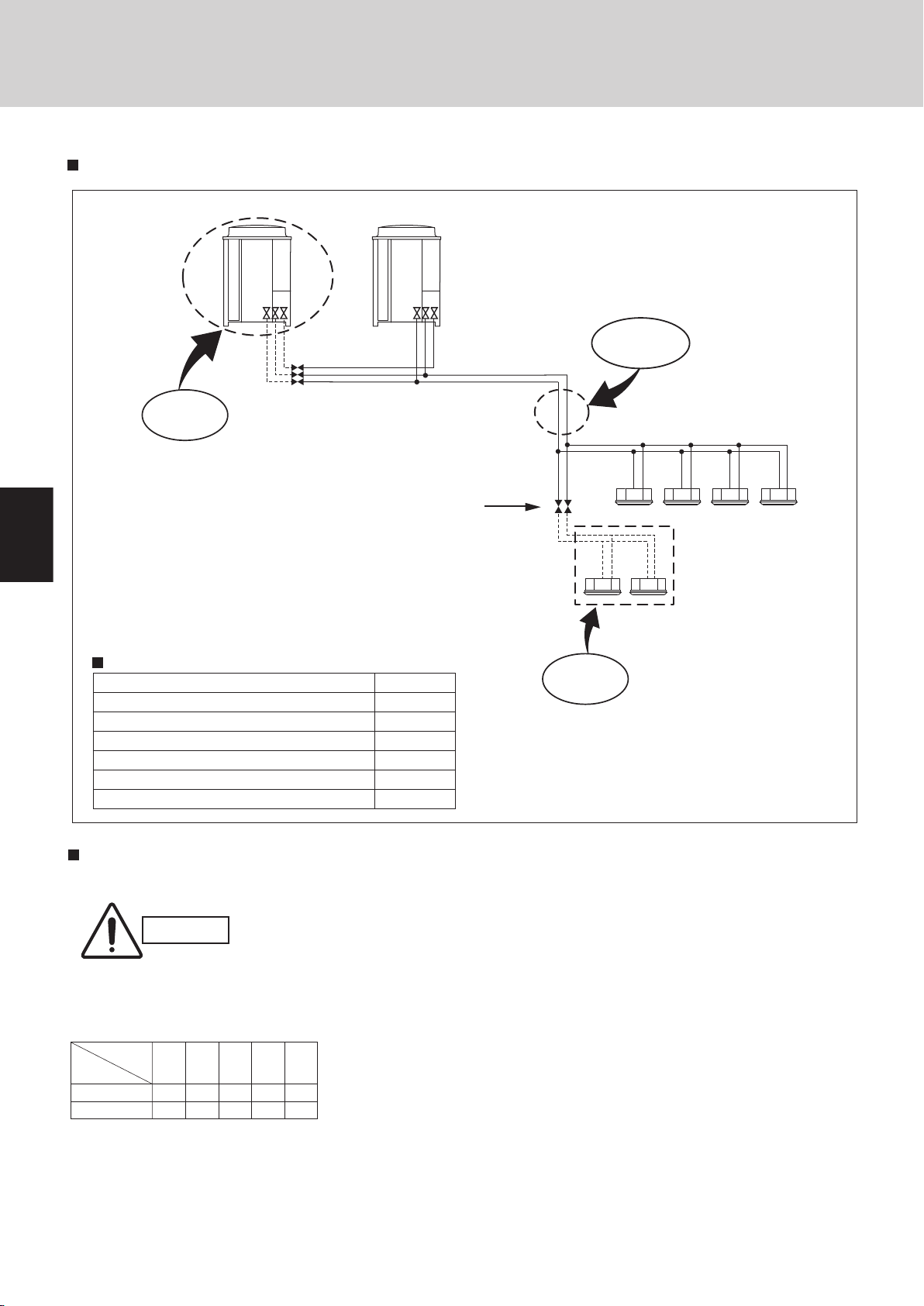
ADDITION
CONCENTRATION
If indoor/outdoor units need servicing, a ball
valve (field supply) cuts off non-operational
units to let other units stay running.
* The capacity after the setting
must not exceed 32 PS.
Since all tubings are
concentrated into
one pipe shaft, you
can minimize piping
space and construction labor
Maximum number of combined outdoor units
Maximum horsepower of combined outdoor units
Maximum number of connectable indoor units
Indoor/outdoor unit capacity ratio
Maximum actual tubing length
Maximum level difference (when outdoor unit is lower)
Maximum total tubing length
2
32 HP
40
50~130%
492 ft
164 (131) ft
984 ft
System limitations
CONNECTION
If your indoor capacity load
changes in the future, it’s easy to
add on both indoor and outdoor
units using the same tubing.
*If addi tional i nst allat ion of outd oor and ind oor u nit s is
exp ect ed, the sizeof refr igera nt tube sho uld be d ecided
accordin g to the to tal c apa city aft er the a ddi tion.
Combination of outdoor units
The DC inverter unit can be used independently or in combination.
CAUTION
R407C models and R22 models must not be used in combination with each
other.
1
1
2
10
16
10
16
20 26 32
Total horse
power
Inverter unit
Combination of outdoor units
1
2
1
2. Features of W-2WAY ECO-i SYSTEM
2-1. Outline of W-2WAY ECO-i SYSTEM
System example
Outline of W-2Way ECO-i SYSTEM
1-4
Page 9
2. Features of W-2WAY ECO-i SYSTEM
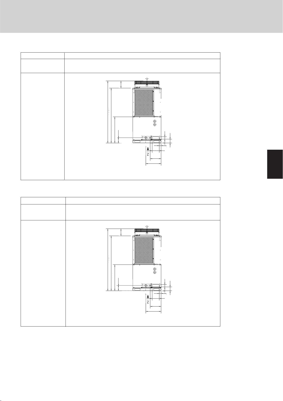
Dimensions
10HP CHDX09053
16HP CHDX14053
Air direction
(Ceiling panel dimensions)
10,16 HP
Air direction
Air direction
31-7/64
(Installation hole pitch)
35-3/64
Top view
Outline of W-2Way ECO-i SYSTEM
Air direction
(Maximum dimensions)
(Installation hole pitch)
(Ceiling panel dimensions)
36-7/32
37-13/32
35-3/64
Unit: in.
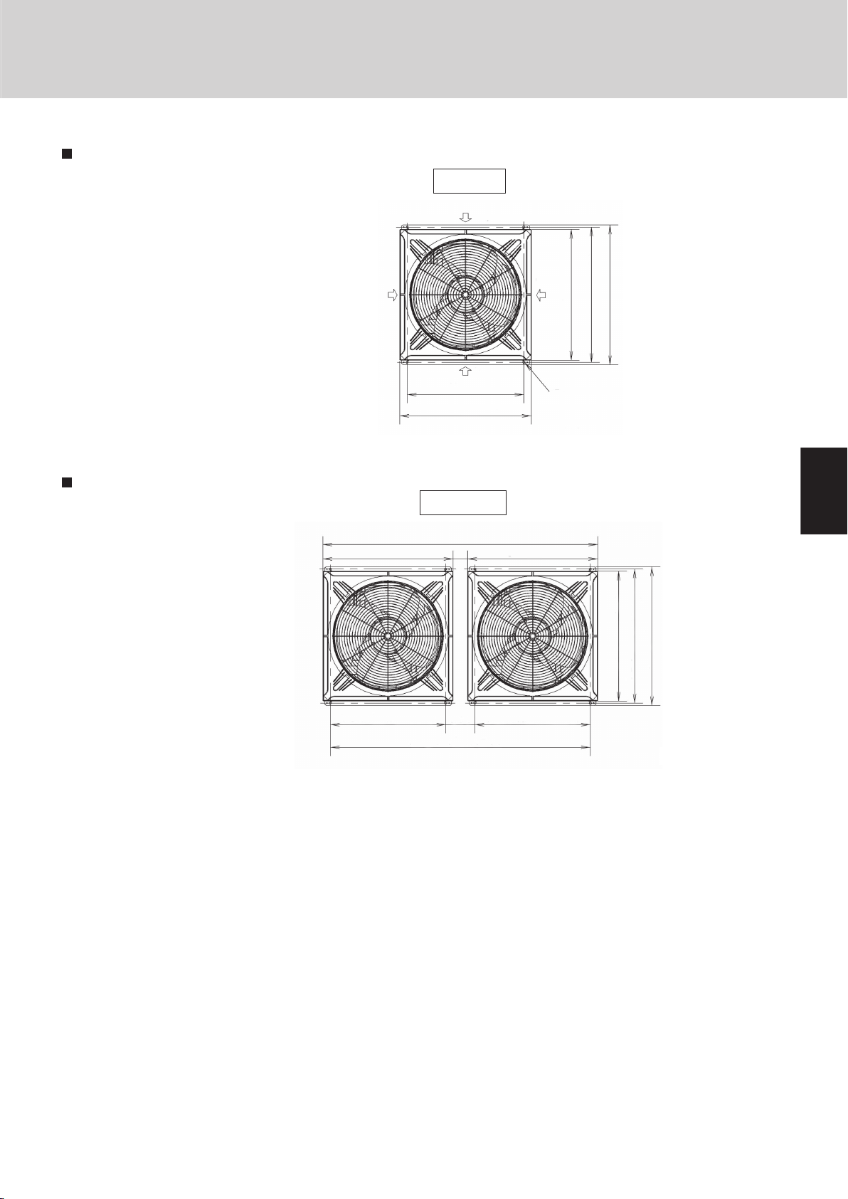
Dimensions of unit combinations
20,26,32 HP
74-1/64 (Ceiling panel dimensions)
35-3/64 (Ceiling panel dimensions) 35-3/64 (Ceiling panel dimensions)
35-3/64 (Ceiling panel dimensions)
31-7/64 (Installation hole pitch)
70-5/64 (Installation hole pitch)
31-7/64 (Installation hole pitch)
Top view
36-7/32 (Installation hole pitch)
37-13/32 (Maximum dimensions)
Unit: in.
1
2
3
4
5
1-5
6
7
8
Page 10
1
2
3
4
5
6
7
8
1
2
3
4
5
6
7
8
In case of 32 HP system
Capacity
32
28
24
20
16
12
8
4
DC1
DC2
AC11
AC21
AC12
AC22
DC1
DC1
DC2
AC11
DC1
DC2
AC11
AC21
DC1
DC2
AC11
AC21
AC12
DC2
DC1
DC2
LOAD --->
Example of 2 unit connection
DC1
AC11
AC12
Unit 1
DC2
AC21
AC22
Unit 2
DC3
AC31
AC32
Unit 3
Outline of W-2Way ECO-i SYSTEM
2. Features of W-2WAY ECO-i SYSTEM
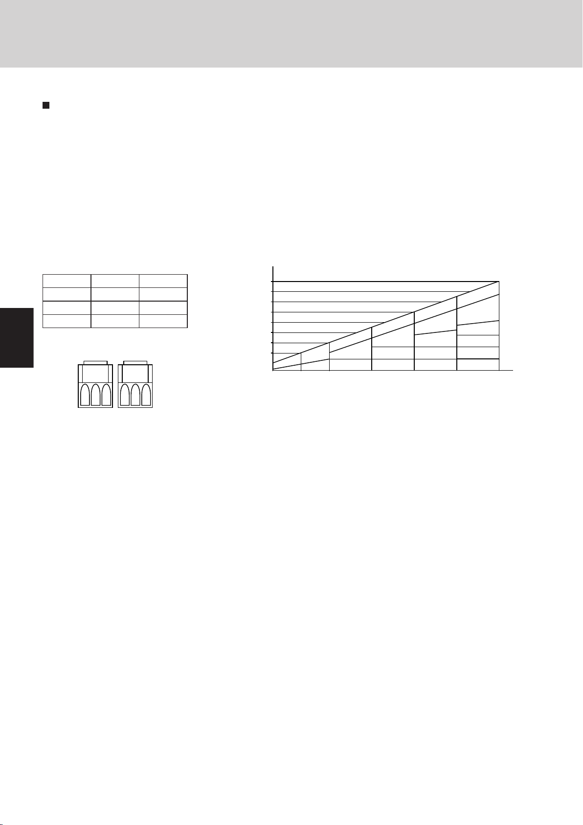
Capacity control
The compressor combination (DC inverter compressor + constant-speed compressor) allows smooth capacity control from 0.8
HP to 32 HP.
Realization of smooth capacity control
from 0.8HP to 32HP
Capacity control is possible smoothly with a DC
inverter compressor.The right graph shows the
image of the operating combination of compressors in case of 32HP system.In actual operation,
the combination will be changed by operationg
condition, operating time amount, priority of compressor and so on.
Comp. HP Unit1(main) Unit2(sub1)
DC comp. 4.0 4.0
AC1 comp. 6.0 6.0
AC2 comp. 6.0 6.0
*32HP = CHDX14053 Type x2
1-6
Page 11

Design of W-2WAY ECO-i SYSTEM Unit Specifications
1
2
3
4
5
6
7
8
Contents
2. DESIGN OF W-2WAY ECO-i SYSTEM
1. Model Selecting and Capacity Calculator ........................................................................2-2
2. System Design ..................................................................................................................2-17
3. Electrical Wiring ................................................................................................................2-23
4. Installation Instructions ...................................................................................................2-27
2-1
Page 12
Design of W-2WAY ECO-i SYSTEM Unit Specifications
1
2
3
4
5
6
7
8
1
2
3
4
5
6
7
8
1
2
3
4
5
6
7
8
50
14
23
32
41
50
59
68
77
86
95
104
113
Indoor air intake temp.
°
F (WB)
Outdoor air intake temp.
°
F (DB)
59
57
109
68 77 86
Operating
range
50
5
-4
14
23
32
41
50
59
68
77
Indoor air intake temp.
°
F (DB)
Outdoor air intake temp. °F (WB)
59 68 77 86 95
Operating
range
Cooling
Heating
1. Model Selecting and Capacity Calculator
1-1. Operating Range
2-2
Page 13
1
2
3
4
5
6
7
8
2-3
Design of W-2WAY ECO-i SYSTEM Unit Specifications
1
2
3
4
5
6
7
8
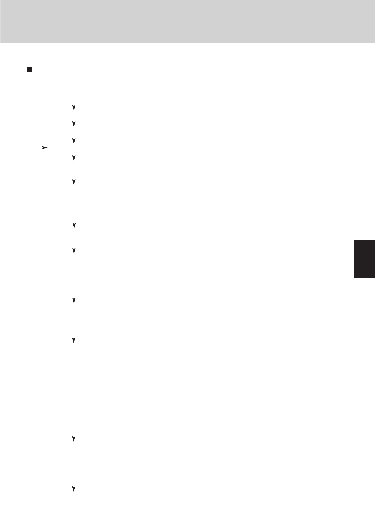
Select the model and calculate the capacity for each refrigerant system according to the procedure shown below.
Calculation of the indoor air-conditioning load
●
Calculate the maximum air-conditioning load for each room or zone.
Selection of an air conditioning system
●
Select the ideal air conditioning system for air conditioning of each room or zone.
Design of the control system
●
Design a suitable control system for the selected air conditioning system.
Preliminary selection of indoor and outdoor units
●
Make preliminary selections that are within the allowable range for the system.
........
2-4 ~ 2-10
Check of the tubing length and elevation difference
●
Check that the length of refrigerant tubing and the elevation difference are within the allowable
ranges.......................................................................................................................................
2-4
Calculation of the corrected outdoor unit capacity
●
Capacity correction coefficient for model.................................................................... 2-11, 13, 14
●
Capacity correction coefficient for outdoor temperature conditions ..................................2-11, 13
●
Capacity correction coefficient for tubing length and elevation difference ........................ 2-11, 14
●
Heating capacity correction coefficient for frosting/defrosting .......................................... 2-11, 13
Calculation of the corrected capacity for each indoor unit
●
Capacity correction coefficient for indoor temperature conditions .................................... 2-11, 14
●
Capacity distribution ratio based on the tubing length and elevation difference .............. 2-11, 14
Calculation of the actual capacity for each indoor unit
●
Calculate the corrected indoor/outdoor capacity ratio, based on the corrected outdoor unit
capacity and the total corrected capacity of all indoor units in the same system. Use the result to
calculate the capacity correction coefficient for the indoor units.................................
2-11 ~ 2-14
●
Multiply the corrected capacity of each indoor unit by the capacity correction coefficient to calcu-
late the actual capacity for each indoor unit. .......................................................................... 2-12
Recheck of the actual capacity for each indoor unit
●
If the capacity is inadequate, reexamine the unit combinations.
Example 1: Increasing the outdoor unit capacity.................................................................... 2-18
Example 2: Increasing the indoor unit capacity ...................................................................... 2-19
●
Increasing the tubing size ...................................................................................................... 2-20
Design of tubing
●
Create a tubing design which minimizes the amount of additional refrigerant charge as much as
possible. .......................................................................................................................... 2-4 ~ 2-6
●
If tubing extension for additional unit is expected in the future, create the tubing design with
adequate consideration for this extension.
●
Select the tubing size for the main tube (LA) up to the No. 1 distribution joint based on the rated
cooling capacity of the outdoor unit. Select tubing sizes after the distribution point based on the
total rated cooling capacity of the connected indoor units.
●
Increasing the tubing size of the wide tubes can reduce the loss of capacity caused by longer
tubing lengths. (Only the main wide tube with the largest tube diameter (main tube LA and main
tubes after the distribution point that are the same size as LA) can be changed.) In this case, it is
necessary to recalculate the actual indoor unit capacities. ....................................................
2-20
Calculation of additional refrigerant charge amount
●
Calculate the additional refrigerant charge from the diameters and lengths of the refrigerant tubing. Even if the wide tubing diameter was increased, determine the additional refrigerant charge
based only on the narrow tubing size.....................................................................................
2-21
●
Check the minimum indoor capacity (limit density) with respect to the amount of refrigerant. If the
limit density is exceeded, be sure to install ventilation equipment or take other corrective steps. 2-22
Design of electrical wiring capacity
●
Select a wiring capacity according to the method of power supply. ...................................... 2-24
1. Model Selecting and Capacity Calculator
1-2. Procedure for Selecting Models and Calculating Capacity
Model Selection Procedure
Page 14
Design of W-2WAY ECO-i SYSTEM Unit Specifications
1
2
3
4
5
6
7
8
1
2
3
4
5
6
7
8
1
2
3
4
5
6
7
8
R410A distribution joint
APR-CHP680BA (for outdoor unit)
APR-CHP680BA (for outdoor unit)
APR-CHP680BA (for outdoor unit)
APR-CHP680BA (for outdoor unit)
APR-P1350BA (for indoor unit)
Explanation of symbols
Distribution joint
(APR: purchased separately)
Solidly welded shut
(pinch weld)
Balance tubing
( 1/4")
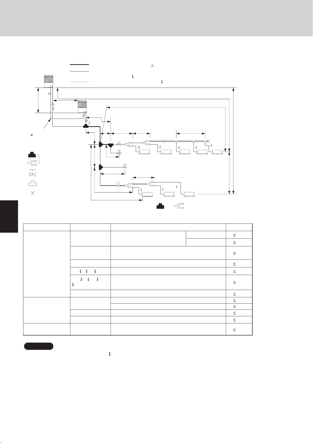
Main distribution tubes LC – LG are selected according to the capacity after the distribution joint.
Sizes of indoor unit connection tubing 1 – 40 are determined by the connection tubing sizes on the indoor units.
Main tubing length LM = LA + LB … 262 ft
1.
2.
3. The outdoor connection main tubing ( B portion) is determined by the total capacity of the outdoor units that are connected to the tube ends.
4.
Ball valve (field supply)
T-joint (field supply)
Note: Do not use commercially available T-joints for the liquid tubing and parts.
* Be sure to use special R410A distribution joints (APR: purchased separately) for outdoor unit connections and tubing branches.
Table 2-1 Ranges that Apply to Refrigerant Tubing Lengths and to Differences in Installation Heights
Select the installation location so that the length and size of refrigerant tubing are within the allowable range shown in the figure below.
Item Mark Contents Length (ft.)
L1 Max. tubing length
Actual length 492
Equivalent length 574
L (L2 – L4)
Difference between max. length and min.
length from the No.1 distribution joint
131
LM Max. length of main tubing (at max. diameter) 262
1, 2... 40
Max. length of each distribution tube 98
L1+ 1+ 2... 39+
A+LE+LF+LG
Total max. tubing length including length of
each distribution tube (only liquid tubing)
984
L5
L3
Distance between outdoor units
32
H1
When outdoor unit is installed higher than indoor unit 164
When outdoor unit is installed lower than indoor unit 131
H2
Max. difference between indoor units 49
H3 Max. difference between outdoor units
13
L = Length, H=Height
Allowable tubing
length
Allowable elevation
difference
*3
6.6
Allowable length of
joint tubing
T-joint tubing (field-supply); Max. tubing length between
the first T-joint and solidly welded-shut end point
1: The outdoor connection main tubing ( B portion) is determined by the total capacity of the outdoor units that are connected to
the tube ends.
2: If the longest tubing length (L1) exceeds 295 ft. (equivalent length), increase the sizes of the main tubes (LM) by 1 rank for gas
tubes and liquid tubes. (Use a field supply reducer.) (Select the tube size from the table of main tube sizes (Table 2-5) on the
following page (LA table), and from the table of refrigerant tubing sizes (Table 2-10) on the second following page.)
3: If the longest main tube length (LM) exceeds 164 ft., increase the main tube size at the portion before 164 ft. by 1 rank for the
gas tubes. (Use a field supply reducer.)
(For the portion that exceeds 164 ft., set based on the main tube sizes (LA) listed in the table on the following page.)
4: If the size of the existing tubing is already larger than the standard tubing size, it is not necessary to further increase the size.
* If the existing tubing is used, and the amount of on-site additional refrigerant charge exceeds the value listed below, then
change the size of the tubing to reduce the amount of refrigerant.
Max. additional charge for 1 outdoor unit: 62 lbs
Max. additional charge for 2 outdoor units: 111lbs
NOTE
L5
LA
LE
LM
LB LC
L2
L4
LF
LD L3
LG
H2
H3
H1
L1
2
3
1
5
4
A
B
38
39
40
For
extension
For
extension
Max. 1.3ft
Max. 1.3ft
1. Model Selecting and Capacity Calculator
1-3. Tubing Length
2-4
Page 15
1
2
3
4
5
6
7
8
2-5
Design of W-2WAY ECO-i SYSTEM Unit Specifications
1
2
3
4
5
6
7
8
1. Model Selecting and Capacity Calculator
Table 2-2 Refrigerant Charge Amount at Shipment (for outdoor unit)
DC
(oz)
Additional refrigerant charge amount is calculated from the liquid tubing total length as follows.
Table 2-3 Amount of Refrigerant Charge Per Meter, According to Liquid Tubing Size
Liquid tubing size Amount of refrigerant
(in. (mm)) charge (oz/ft.)
ø1/4" (ø6.35) 0.279
ø3/8" (ø9.52) 0.602
ø1/2" (ø12.7) 1.38
ø5/8" (ø15.88) 1.99
ø3/4" (ø19.05) 2.78
ø7/8" (ø22.22) 3.93
CHDX09053 CHDX14053
423 458
Required amount of charge = (Amount of refrigerant charge per
meter of each size of liquid tube × its tube length) + (...) + (...)
* Always charge accurately using a scale for weighing.
* If the existing tubing is used, and the amount of on-site additional
refrigerant charge exceeds the value listed below, then change the
size of the tubing to reduce the amount of refrigerant.
Max. additional charge for 1 outdoor unit : 62 lbs
Max. additional charge for 2 outdoor units : 111 lbs
Table 2-4 System Limitations
Max. No. allowable connected outdoor units 2
Max. capacity allowable connected outdoor units 307,100 BTU/h (32 hp, 90 kW)
Max. connectable indoor units 40
Max. allowable indoor/outdoor capacity ratio 50 – 130 %
*1: Up to 2 units can be connected if the system has been extended.
*1
Page 16
1
2
3
4
5
6
7
8
1
2
3
4
5
6
7
8
1
2
3
4
5
6
7
8
32
249,100
(73.0)
26
ø7/8"
(ø22.22)
10
95,500
(28.0)
ø1/2"
(ø12.7)
153,600
(45.0)
16
ø1-1/8"
(ø28.58)
ø5/8"
(ø15.88)
10
10
16
10
16
16
191,100
(56.0)
20
ø3/4"
(ø19.05)
ø1-3/8"
(ø34.92)
ø3/8"
(ø9.52)
307,100
(90.0)
16 10
BTU/h
(kW)
Total system horsepower
Combined outdoor units
Gas tubing
Liquid tubing
ø3/4"
(ø19.05)
ø1-3/8"
(ø34.93)
ø5/8"
(ø15.88)
ø1-1/8"
(ø28.58)
ø1/2"
(ø12.7)
ø1-1/8"
(ø28.58)
ø3/8"
(ø9.52)
ø3/4"
(ø19.05)
ø3/8"
(ø9.52)
ø5/8"
(ø15.88)
ø3/8"
(ø9.52)
ø1/2"
(ø12.7)
Gas tubing
Liquid tubing
–
238,900
(25 hp)
178,800
(19 hp)
ø1/2"
(ø12.7)
ø1-1/8"
(ø28.58)
178,800
(19 hp)
143,300
(15 hp)
24,200
(2.5 hp)
24,200
(2.5 hp)
–
54,600
(6 hp)
54,600
(6 hp)
238,900
(25 hp)
76,800
(8.1 hp)
ø3/8"
(ø9.52)
ø7/8"
(ø22.22)
76,800
(8.1 hp)
102,400
(11 hp)
102,400
(11 hp)
Below BTU/h
Over BTU/h
143,300
(15 hp)
hp = horsepower
Tubing size
Total capacity
after distribution
Design of W-2WAY ECO-i SYSTEM Unit Specifications
1. Model Selecting and Capacity Calculator
1-4 Tubing Size
Table 2-5 Main Tubing Size (LA)
*1: If future extension is planned, select the tubing diameter based on the total horsepower after extension.
However extension is not possible if the resulting tubing size is two ranks higher.
*2: The balance tube (outdoor unit tube) diameter is ø1/4".
*3: Type 1 tubing should be used for the refrigerant tubes.
*4: If the length of the longest tube (L1) exceeds 295 ft. (equivalent length), increase the main tube (LM) size by 1 rank for the gas
and liquid tubes. (Use field-supply reducers.) (Select from Table 2-5 and Table 2-10.)
*5: If the longest main tube length (LM) exceeds 164 ft., increase the main tube size at the portion before 164 ft. by 1 rank for the
gas tubes.
(For the portion that exceeds 164 ft., set based on the main tube sizes (LA) listed in the table above.)
Unit: in. (mm)
Size of tubing (lB) between outdoor units
Select the size of tubing between outdoor units based on the main tubing size (LA) as given in the table above.
Table 2-6 Main Tubing Size After Distribution (LB, LC...)
Note: In case the total capacity of connected indoor units exceeds the total capacity of the outdoor units, select the main tubing
size for the total capacity of the outdoor units. (Especially the main tubing segments of LA, LB and LF.)
Unit: in. (mm)
2-6
Page 17
1
2
3
4
5
6
7
8
2-7
Design of W-2WAY ECO-i SYSTEM Unit Specifications
1
2
3
4
5
6
7
8
ø7/8"
(ø22.22)
ø3/8" (ø9.52)
ø1/4" (ø6.35)
95,500
(28.0)
153,600
(45.0)
ø1-1/8"
(ø28.58)
Flare connection
Brazing connection
ø1/2" (ø12.7)
Flare connection
( A – B)
Balance tubing
Liquid tubing
Gas tubing
BTU/h
(kW)
Balance tube
Liquid tube
Gas tube
ø5/8" (ø15.88)
ø3/8" (ø9.52) ø1/4" (ø6.35)
ø1/2" (ø12.7)
Gas tubing
Liquid tubing
Indoor unit type 7 9 12 18
24
36 48
1. Model Selecting and Capacity Calculator
Table 2-7 Amount of Refrigerant Charge
Liquid tubing size Amount of refrigerant
(in. (mm)) charge (oz/ft.)
ø1/4" (ø6.35) 0.279
ø3/8" (ø9.52) 0.602
ø1/2" (ø12.7) 1.38
ø5/8" (ø15.88) 1.99
ø3/4" (ø19.05) 2.78
ø7/8" (ø22.22) 3.93
Table 2-8 Outdoor Unit Tubing Connection Size
Unit: in. (mm)
Table 2-9 Indoor Unit Tubing Connection Size
Note: Use C1220T-1/2H material for tubing over ø3/4" (ø22.22).
Table 2-10 Refrigerant tubing (Existing tubing can be used.)
Material O Material 1/2H • H
ø1/4" (ø6.35) t1/32" (0.8) ø7/8" (ø22.22) t5/128" (1.0)
ø3/8" (ø9.52) t1/32" (0.8) ø1" (ø25.40) t5/128" (1.0)
ø1/2" (ø12.7) t1/32" (0.8) ø1-1/8" (ø28.58) t5/128" (1.0)
ø5/8" (ø15.88) t5/128" (1.0) ø1-1/4" (ø31.75) t3/64" (1.1)
ø3/4" (ø19.05) over t5/128" (1.0) ø1-3/8" (ø34.93) over t3/64" (1.15)
Tubing size (in. (mm))
Unit: in. (mm)
* When bending the tubes, use a bending
radius that is at least 4 times the outer
diameter of the tubes.
In addition, take sufficient care to avoid
crushing or damaging the tubes when
bending them.
Page 18
Design of W-2WAY ECO-i SYSTEM Unit Specifications
1
2
3
4
5
6
7
8
1
2
3
4
5
6
7
8
1
2
3
4
5
6
7
8
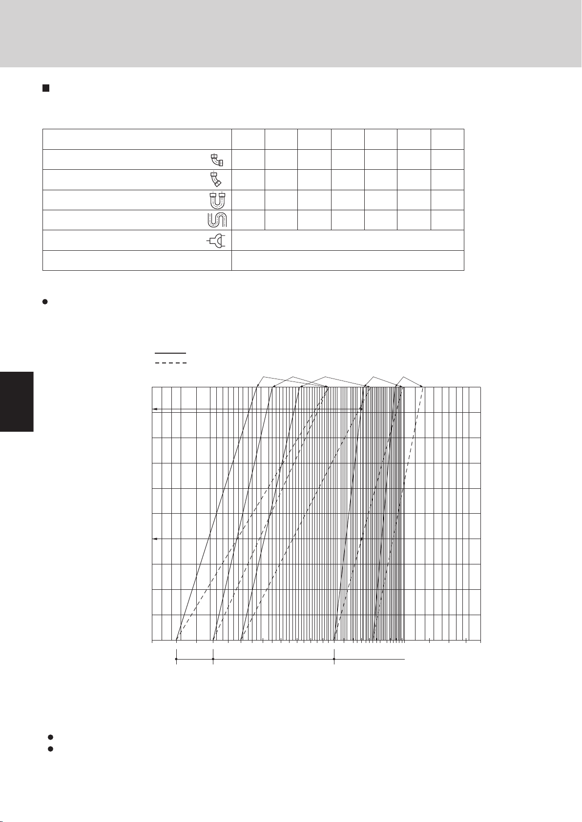
Wide tubing size (mm) 12.7 15.88 19.05 22.22 25.4 28.58 31.8 38.1
90o elbow 0.3 0.35 0.42
0.48
0.52 0.57 0.7
0.79
45o elbow 0.23 0.26 0.32
0.36
0.39 0.43 0.53 0.59
U-shape tube bent (R60 100 mm) 0.9 1.05 1.26 1.44 1.56 1.71 2.1
2.37
Trap bend
2.3
2.8 3.2 3.8 4.3 4.7 5.0
5.8
Y-branch distribution joint Equivalent length conversion not needed.
Ball valve for service Equivalent length conversion not needed.
Cooling
Heating
95
94
93
92
91
90
96
97
98
99
100
Capacity ratio based on Gas
tube diameter (%)
Recommended Gas tubes diameter (in)
ø3/4” ø7/8”
ø7/8” ø1-1/8”
ø1-1/8”
ø1-3/8”
ø1-3/8”
ø1”
10 12 14 16 18 20 26 30 35 40 45 46 47 48
Gas tubing size (in. (mm))
1/2"
(12.7)
5/8"
(15.88)
3/4"
(19.05)
7/8"
(22.22)
1"
(25.4)
1-1/8"
(28.58)
1-3/8"
(34.93)
90° elbow
1 1.1 1.4 1.6 1.7 1.9 2.5
45° elbow 0.8 0.9 1
1.2
1.3 1.4 1.8
U-shape tube bent (R2-3/8" – 4" (60 – 100)) 3 3.4 4.1 4.7 5.1 5.6 7.4
Trap bend
7.5 9.2 10.5 12.5 14.1 15.4 19.2
Y-branch distribution joint Equivalent length conversion not needed.
Ball valve for service Equivalent length conversion not needed.
1. Model Selecting and Capacity Calculator
Straight equivalent length of joints
Design the tubing system by referring to the following table for the straight equivalent length of joints.
Table 2-11 Straight Equivalent Length of Joints
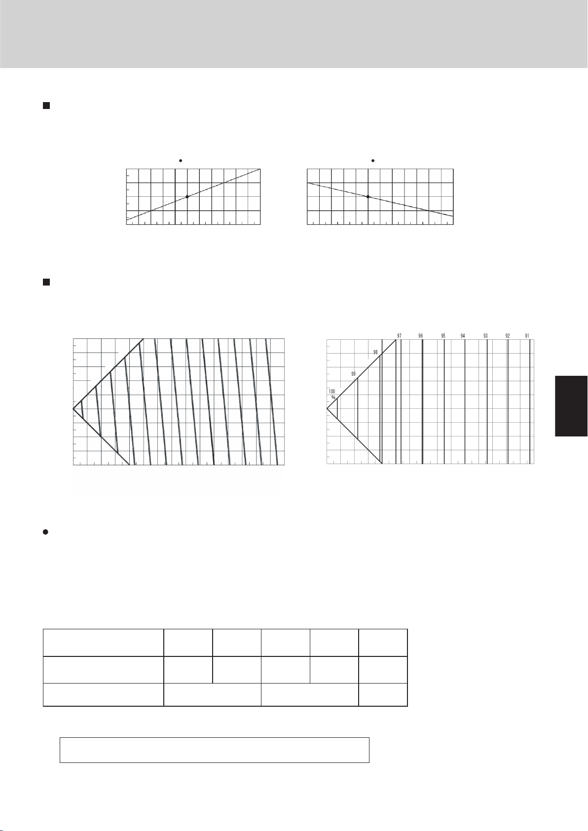
Capacity loss caused by differences in tubing diameters
* Capacity loss will occur if a tubing system that matches the horsepower is not selected (for example, if a tubing system was
determined and installed with no plan for extension and extension occurs later). The loss rate can be found from the graph
below.
Unit: ft.
(Reading the graph)
<Example 1>
Currently a 16 HP system and ø1-1/8" Gas tubings are used. Subsequently the system is expanded, with 16 HP added to the
same tubing system.
Horsepower after extension: 16 + 16 = 32 HP
From the graph above: Cooling: Capacity ratio is 90.8%. Actual capacity = 32 × 0.908 = 29.1 HP
Heating: Capacity ratio is 96.0%. Actual capacity = 32 × 0.960 = 30.7 HP
2-8
Page 19
1
2
3
4
5
6
7
8
2-9
Design of W-2WAY ECO-i SYSTEM Unit Specifications
1
2
3
4
5
6
7
8
WARNING
CAUTION
WARNING
0 0
57
114
170
227
284
341
398
454
511
568
625
682
738
795
852
909
966
1022
1079
1136
0
500
1000
1500
2000
2500
3000
3500
4000
4500
5000
5500
6000
6500
7000
7500
8000
8500
9000
9500
10000
1000500 1500 2000 2500 3000
Total amount of refrigerant
Min. indoor volume
Min. indoor floor area
(when the ceilin
g
is 8.8 ft. hi
g
h)
ft.
3
ft.
2
oz
Range above
the density limit of
0.3 oz/ft.
3
(countermeasures
needed)
Range below
the density limit of
0.3 oz/ft.
3
(countermeasures
not needed)
1. Model Selecting and Capacity Calculator
Additional refrigerant charge amount
Additional refrigerant charge amount is calculated from the liquid tubing total length as follows.
Table 2-12 Amount of Refrigerant Charge Per Meter, According to Liquid Tubing Size
Liquid tubing size Amount of refrigerant
(in. (mm)) charge (oz/ft.)
ø1/4" (ø6.35) 0.279
ø3/8" (ø9.52) 0.602
ø1/2" (ø12.7) 1.38
ø5/8" (ø15.88) 1.99
ø3/4" (ø19.05) 2.78
ø7/8" (ø22.22) 3.93
Check of limit density
Required amount of charge = (Amount of refrigerant charge per
meter of each size of liquid tube × its tube length) + (...) + (...)
* Always charge accurately using a scale for weighing.
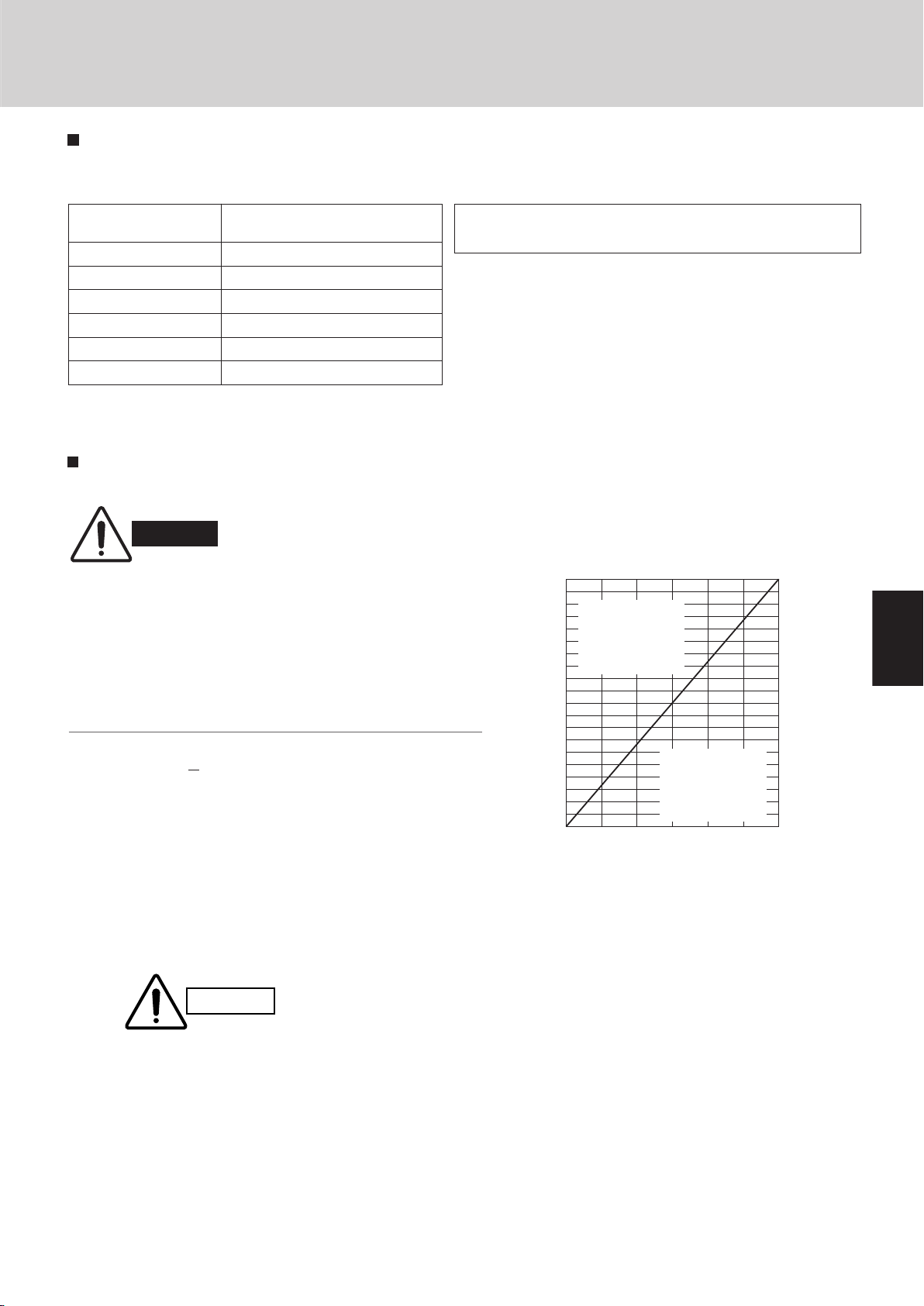
1-5. Check of Limit Density
When installing an air conditioner in a room, it is necessary to
ensure that even if the refrigerant gas accidentally leaks out, its
density does not exceed the limit level for that room.
If the density could exceed the limit level, it is necessary to provide
an opening between the unit and the adjacent room, or to install
mechanical ventilation which is interlocked with a leak detector.
(Total refrigerant charged amount: oz)
(Min. indoor volume where the indoor unit is installed: ft.3)
<
The limit density of refrigerant R410A which is used in this unit is
0.3 oz/ft.3 (ISO 5149).
The shipped outdoor unit comes charged with the amount of refrigerant fixed for each type, so add it to the amount that is charged in
the field. (For the refrigerant charge amount at shipment, refer to the
unit’s nameplate.)
Always check the gas density
limit for the room in which the
unit is installed.
Limit density 0.3 (oz/ft.3)
Pay special attention to any location,
such as a basement, etc., where leaking
refrigerant can accumulate, since
refrigerant gas is heavier than air.
Minimum indoor volume & floor area as against the amount
of refrigerant is roughly as given in the following table.
Page 20

1
2
3
4
5
6
7
8
1
2
3
4
5
6
7
8
1
2
3
4
5
6
7
8
Capacity distribution ratio for each indoor unit (3) = Correction coefficient for that indoor unit / Correction coefficient for the outdoor uni
t
However, the corrected cooling capacity of each indoor unit is found as shown below.
If (2) < 100% and (2)
×
(3) > 100%: Corrected cooling capacity for that indoor unit [5] = Rated cooling capacity for that indoor unit
If (2) ≥ 100%: Corrected cooling capacity for that indoor unit (5) = Rated cooling capacity for that indoor unit
×
(2)
Capacity distribution ratio for each indoor unit (3) = Correction coefficient for that indoor unit / Correction coefficient for the outdoor uni
t
Design of W-2WAY ECO-i SYSTEM Unit Specifications
1. Model Selecting and Capacity Calculator
1-6. Calculation of Actual Capacity of Indoor Unit
Calculating the actual capacity of each indoor unit
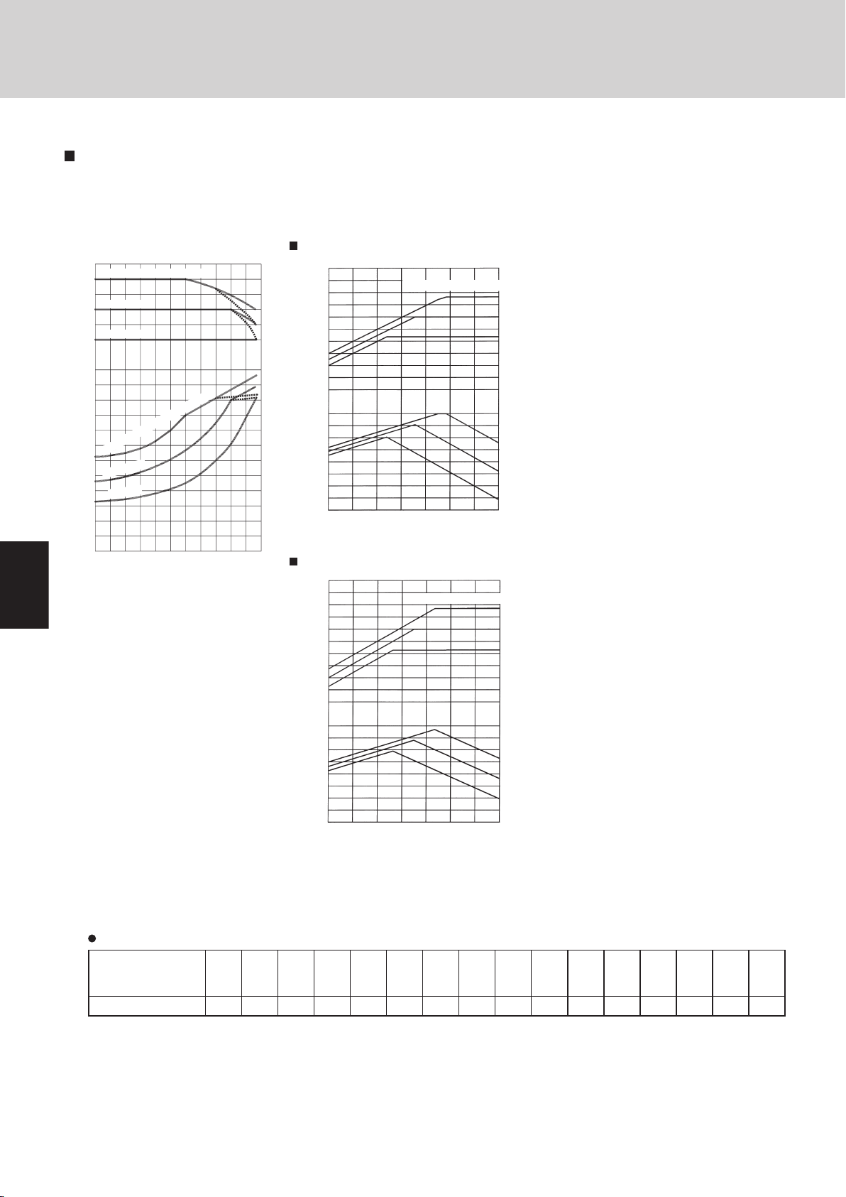
Because the capacity of a multi air-conditioner changes according to the temperature conditions, tubing length, elevation difference and other factors, select the correct model after taking into account the various correction values. When selecting The
model, calculate the corrected capacities of the outdoor unit and each indoor unit. Use the corrected outdoor unit capacity and
the total corrected capacity of all the indoor units to calculate the actual final capacity of each indoor unit.
1. Outdoor unit capacity correction coefficient
Find the outdoor unit capacity correction coefficient for the following items.
(1) Capacity correction for the outdoor unit model
The capacity correction coefficient is 1.00.
(2) Capacity correction for the outdoor unit temperature conditions
From the graph of capacity characteristics on page 2-12, use the outdoor temperature to find the capacity correction coefficient.
(3) Capacity correction for the outdoor unit tubing length and elevation difference
From the graph of capacity change characteristics on page 2-13, use the tubing length and elevation difference to find the
capacity correction coefficient.
The outdoor unit correction coefficient is the value which corresponds to the most demanding indoor unit.
(4) Capacity correction for outdoor unit frosting/defrosting during heating
From the table on page 2-12, find the capacity correction coefficient.
2. Indoor unit capacity correction coefficients
Find the indoor unit capacity correction coefficient for the following items.
(2) Capacity correction for the indoor unit temperature conditions
From the graph of capacity characteristics on page 2-13, use the indoor temperature to find the capacity correction coefficient.
(3) Capacity distribution ratio based on the indoor unit tubing length and elevation difference
First, in the same way as for the outdoor unit, use the tubing length and elevation difference for each indoor unit to find the
correction coefficient from the graph of capacity change characteristics on page 2-13. Then divide the result by the outdoor
unit correction coefficient to find the capacity distribution ratio for each indoor unit.
3. Calculating the corrected capacities for the outdoor unit and each indoor unit
The corrected capacities for the outdoor unit and each indoor unit are calculated form the formula below.
<Cooling>
Outdoor unit corrected cooling capacity (5) = Outdoor unit rated cooling capacity × Correction coefficient for model ((1)
Page 2-12) × Correction coefficient for outdoor temperature conditions ((2)
Page 2-12) × Correction coefficient for tubing length and elevation difference
((3) Page 2-13)
* However, if the outdoor unit corrected cooling capacity [5] is greater than 100%, then the outdoor unit corrected cooling
capacity [5] is considered to be 100%.
Corrected cooling capacity of each indoor unit (5) = Rated cooling capacity for that indoor unit × Correction coefficient for
indoor temperature conditions at that indoor unit ((2) Page 2-13) × Distribution ratio based on tubing length and elevation difference at that indoor unit ((3) Page 2-13)
2-10
Page 21

1
2
3
4
5
6
7
8
2-11
Design of W-2WAY ECO-i SYSTEM Unit Specifications
1
2
3
4
5
6
7
8
However, the corrected heating capacity of each indoor unit is found as shown below.
If (2) < 100% and (2) ×(3) > 100%: Corrected heating capacity for that indoor unit (5) = Rated heating capacity for that indoor unit
If (2) ≥ 100%: Corrected heating capacity for that indoor unit (5) = Rated heating capacity for that indoor unit ×(2)
1. Model Selecting and Capacity Calculator
<Heating>
Outdoor unit corrected heating capacity (5) = Outdoor unit rated heating capacity × Correction coefficient for model ((1)
Page 2-12) × Correction coefficient for outdoor temperature conditions ((2)
Page 2-12) × Correction coefficient for tubing length and elevation difference
((3) Page 2-13) × Correction coefficient for frosting/defrosting ((4) Page
* However, if the outdoor unit corrected heating capacity [5] is greater than 100%, then the outdoor unit corrected heating
capacity is considered to be 100%.
Corrected heating capacity of each indoor unit (5) = Rated heating capacity for that indoor unit × Correction coefficient for
indoor temperature conditions at that indoor unit ((2) Page 2-13) × Distribution ratio based on tubing length and elevation
difference at that indoor unit.
* Characteristic graphs are shown on the pages listed above next to each correction item. Find each correction coefficient
from the appropriate conditions.
2-12)
4. Calculating the actual indoor unit capacity based on the indoor/outdoor corrected capacity ratio
Calculate the actual capacity of each indoor unit from the values (found in (3)) for the corrected outdoor unit capacity and the
corrected capacity of each indoor unit.
<Cooling capacity>
Corrected indoor/outdoor capacity ratio during cooling (Ruc) = Total corrected cooling capacity of all indoor units in that system /
Corrected outdoor unit cooling capacity
If the corrected outdoor unit cooling capacity is greater than or equal to the total corrected unit cooling capacity of all indoor units
in that system (Ruc 1), then:
Actual cooling capacity of each indoor unit (7) = Corrected cooling capacity of each indoor unit (5) (In other words, the correction coefficient (6), based on the corrected indoor/outdoor capacity ratios for each indoor unit, is 1.)
If the corrected outdoor unit cooling capacity is less than the total corrected unit cooling capacity of all indoor units in that system (Ruc > 1), then:
(Actual cooling capacity of each indoor unit (7)) = (Corrected cooling capacity of each indoor unit (5)) × (0.25 × Ruc + 0.75)
/ Ruc
(In other words, the correction coefficient (6), based on the corrected indoor/outdoor capacity ratios for each indoor unit, is
the underlined part in the formula above.)
<Heating capacity>
Corrected indoor/outdoor capacity ratio during heating (Ruh) = Total corrected heating capacity of all indoor units in that system
/ Corrected outdoor unit heating capacity
If the corrected outdoor unit heating capacity is greater than or equal to the total corrected unit heating capacity of all indoor
units in that system (Ruh 1), then:
Actual heating capacity of each indoor unit (7) = Corrected heating capacity of each indoor unit (5)
(In other words, the correction coefficient (6), based on the corrected indoor/outdoor capacity ratios for each indoor unit, is 1.)
If the corrected outdoor unit heating capacity is less than the total corrected unit heating capacity of all indoor units in that system (Ruh > 1), then:
(Actual heating capacity of each indoor unit (7)) = (Corrected heating capacity of each indoor unit (5)) × (0.1 × Ruh + 0.9) /
Ruh
(In other words, the correction coefficient (6), based on the corrected indoor/outdoor capacity ratios for each indoor unit, is
the underlined part in the formula above.)
Page 22
Design of W-2WAY ECO-i SYSTEM Unit Specifications
1
2
3
4
5
6
7
8
1
2
3
4
5
6
7
8
1
2
3
4
5
6
7
8
Indoor unit capacity correction coefficient for Ruc (cooling)
Indoor unit capacity correction coefficient for Ruh (heating)
1.0
0.9
0.8
0.7
0.6
0.5
0.4 0.5 0.6 0.7 0.8 0.9 1.0 1.1 1.2 1.3 1.4 1.5 1.6 1.7 1.8 1.9
2.0
Indoor unit capacity correction coefficient
Corrected indoor/outdoor capacity ratio (Ruc or Ruh)
Outdoor unit cooling capacity
characteristics
Outdoor unit heating capacity
characteristics
Rate of cooling capacity change (%)
Rate of heating capacity change (%)
* Broken line indicates a 16 HP
DC inverter unit
Outdoor air intake temp. (°F DB)
WB = 66°F
Indoor air intake temp. (°F DB)
59
68
77
130
120
110
100
90
80
70
60
50
40
130
120
110
100
90
80
-4 5 14 23 32 41 50 5923 32 41 50 14 59 68 77 86 95 104 113
Outdoor air intake temp. (°F WB)
Indoor air intake temp. (WB) = 60°F
WB = 71°F
1. Model Selecting and Capacity Calculator
Refer to the graph below for the correction coefficients for Ruc and Ruh.
Note: When Ruc or Ruh is less than or equal to 1.0, the indoor unit capacity correction coefficient for both Ruc and Ruh is 1.0.
5. Graph of capacity correction coefficients
Graph of outdoor unit capacity characteristics (1 – (2))
Outdoor unit heating capacity correction coefficient during frosting/defrosting (1 – (4))
Outdoor intake air
(°FWB RH85%)
temp.
Correction coefficient 0.97 0.97 0.97 0.96 0.94 0.91 0.89 0.87 0.87 0.87 0.88 0.89 0.91 0.92 0.95 1.0
* To calculate the heating capacity with consideration for frosting/defrosting operation, multiply the heating capacity found
from the capacity graph by the correction coefficient from the table above.
– 4 5 14 17 21 23 24 28 30 32 33 35 37 39 41 42
2-12
Page 23
1
2
3
4
5
6
7
8
2-13
Design of W-2WAY ECO-i SYSTEM Unit Specifications
1
2
3
4
5
6
7
8
Rate of cooling capacity change (%)
Indoor unit cooling capacity characteristics Indoor unit heating capacity characteristics
indicates the rating point. indicates the rating point.
Indoor air intake temp. (°F WB)
Rate of heating capacity change (%)
Indoor air intake temp. (°F DB)
120
110
100
90
80
110
105
100
95
90
57 59 60 62 64 66 68 69 71 73 75 77 59 60 62 64 66 68 69 71 73 75 77 78
80
<Cooling>
Elevation difference (ft)
Base capacity
change rate
Elevation difference (ft)
*1
92 90 88 86 84 82 80 78 76
94
96
98
100
%
0 98 66 33 131 164 197 230 262 295 328 361 394 427 459 492
164
131
98
66
33
0
-33
-66
-98
-131
Equiv
0 98 66 33 131 164 197 230 262 295 328 361 394 427 459 492
alent length (ft)
Equivalent length (ft)
<Heating>
Base capacity
change rate
164
131
98
66
33
0
-33
-66
-98
-131
1. Model Selecting and Capacity Calculator
Graph of indoor unit capacity characteristics (2 – (2))
Graph of capacity change characteristics resulting from tubing length and elevation difference (1 / 2 – (3))
The positive side for the elevation difference indicates that the outdoor unit is installed at a higher position than the indoor units.
The negative side indicates the opposite.
The capacity loss that is caused by the tubing length can be reduced by increasing the sizes of the discharge tubes and suc-
tion tubes. Refer to Table 2-13 and make the appropriate changes. However be sure that the total length does not exceed the
maximum.
* The only sizes which can be increased are the LM (main tube with the largest diameter) gas tubes, and the changes are
limited to those shown in Table 2-13.
In addition, note that the additional refrigerant charge is determined only by the narrow-tube size.
Table 2-13 Equivalent Length Correction Coefficient when the Size of the Discharge Tubes and Suction Tubes (LM)
is Increased
Standard tubing diameter
(gas tube, in.(mm))
Tubing diameter after change
(gas tube,in.(mm))
Equivalent length correction
coefficient
* If the size of the discharge tubes and suction tubes (LM) have been increased, apply the correction coefficient from Table
2-13 and calculate the equivalent length of the LM section.
Equivalent length of tubing after size increase
= Standard tubing equivalent length × Equivalent length correction coefficient
ø1/2"
(ø12.7)
ø5/8" ø3/4" ø7/8" ø1-1/8" ø1-3/8"
(ø15.88) (ø19.05) (ø22.22) (ø28.58) (ø34.93)
ø5/8"
(ø15.88) (ø19.05) (ø22.22) (ø28.58)
0.4 0.5 0.6
ø3/4" ø7/8" ø1-1/8"
Page 24
Design of W-2WAY ECO-i SYSTEM Unit Specifications
1
2
3
4
5
6
7
8
1
2
3
4
5
6
7
8
1
2
3
4
5
6
7
8
<Cooling>
<Heating>
16HP
10HP
Indoor air intake temp. (°F DB)
59
68
77
59
68
77
Capacity ratio (%)
Input ratio (%)
130
120
110
100
90
80
70
60
50
40
130
120
110
100
90
80
70
60
50
– 4 5 14 23 32 41 50 59
Outdoor air intake temp. (°F WB)
Indoor air intake temp. (°F DB)
59
68
77
59
68
77
Capacity ratio (%)
Input ratio (%)
130
120
110
100
90
80
70
60
50
40
130
120
110
100
90
80
70
60
50
– 4 5 14 23 32 41 50 59
Outdoor air intake temp. (°F WB)
* Broken line indicates 16 HP DC inverter unit
Outdoor air intake temp. ( °F DB)
130
120
110
100
90
80
120
110
100
90
80
70
60
50
40
30
20
10
)
%
(
o
i
t
ar
y
t
i
cap
a
C
)
%( oitar tu
pn
I
14 23 32 41 50 59 68 77 86 95 104 113
WB = 66
°
F
Indoor air intake temp. (WB) = 71°F
WB = 60°F
Indoor air intak
e tem
p
.
(WB) = 71
°
F
WB = 66
°
F
WB = 60
°
F
1. Model Selecting and Capacity Calculator
1-7. Capacity Correction Graph According to Temperature Condition
Capacity characteristics
(The corrected capacity for specific temperature conditions can be found from the graphs below.)
Heating capacity correction coefficients for frost/defrost operation
Outdoor intake air
temp.
(°F WB RH85%)
Correction coefficient 0.97 0.97 0.97 0.96 0.94 0.91 0.89 0.87 0.87 0.87 0.88 0.89 0.91 0.92 0.95 1.0
* The heating capacity when frost/defrost operation is considered is calculated by multiplying the heating capacity found
from the capacity graph by the correction coefficient from the table above.
– 4 5 14 17 21 23 24 28 30 32 33 35 37 39 41 42
2-14
Page 25
1
2
3
4
5
6
7
8
2-15
Design of W-2WAY ECO-i SYSTEM Unit Specifications
1
2
3
4
5
6
7
8
<Cooling>
Elevation difference (ft)
Base capacity
change rate
*1
92 90 88 86 84 82 80 78 76
94
96
98
100
%
0 33 66 98 131 164 197 230 262 295 328 361 394 427 459 4920 33 66 98 131 164 197 230 262 295 328 361 394 427 459 492
164
131
98
66
33
0
–33
–66
–98
–131
Equivalent length (ft)
*1 Sample calculations
(System: 20 HP, 164ft equivalent length, 49ft elevation
difference
The cooling capacity and heating capacity for this system are
found as shown below.)
●
Cooling operation
From the table, the correction coefficient for that horsepower
level is found to be 1.00.
From the graph, the base capacity change rate is found to be
92.0%.
92.0%×1.00 = 92.0%
Capacity change rate is 92.0%.
(56.0kW×92.0% = 51.5kW)
92.0% = 175,800 BTU/h
Cooling capacity is
175,800 BTU/h (51.5 kW)
●
Heating operation
From the table, the correction coefficient for that horsepower
level is found to be 1.00.
From the graph, the base capacity change rate is found to be
97.2%.
97.2%
×
1.00 = 97.2%
Because the calculation result exceeds 97.2%, the capacity
change rate is 97.2%.
(63.0kW
×
97.2% = 61.2kW) Heating capacity is
209,000 BTU/h (61.2 kW)
Cooling Heating
Item
Model (SPW-)
Cooling
capacity
(kW)
Power
consumption
(kW)
Heating
capacity
(kW)
Power
consumption
(kW)
<50Hz models>
22.4
28.0
33.5
40.0
45.0
5.99
7.90
9.58
11.6
13.3
25.0
31.5
37.5
45.0
50.0
6.17
7.15
9.60
11.5
13.2
Equivalent length (ft)
<Heating>
Base capacity
change rate
164
131
98
66
33
0
–33
–66
–98
–131
0 33 66 98 131 164 197 230 262 295 328 361 394 427 459 492
Elevation difference (ft)
191,100 BTU/h
×
97.2% = 209,000 BTU/h215,000 BTU/h
×
1. Model Selecting and Capacity Calculator
Rated performance values
Type
1-8. Capacity Correction Graph According to Tubing Length and Elevation Difference
90 95,500(28.0) 27,000(7.90) 107,500(31.5) 26,500(7.75)
140 153,600(45.0) 45,400(13.3) 170,600(50.0) 45,000(13.2)
Item Cooling Heating
Cooling capacity
BTU/h(kW)
Capacity change characteristics
Power consumption
BTU/h(kW)
Heating capacity
BTU/h(kW)
Power consumption
BTU/h(kW)
NOTE
The positive side for the elevation difference indicates that
the outdoor unit is installed at a higher position than the
indoor units. The negative side indicates the opposite.
Page 26
1
2
3
4
5
6
7
8
1
2
3
4
5
6
7
8
Design of W-2WAY ECO-i SYSTEM Unit Specifications
1. Model Selecting and Capacity Calculator
If the maximum tubing length (L1) exceeds 295 ft (equivalent length), increase the tubing size of the main liquid, gas tubes (LM)
by one rank.
However, the upper limit for the gas tube size is ø1-5/8".
Increasing the tubing size of the gas tubes can reduce the loss of capacity caused by longer tubing lengths.
Refer to Table 2-13 to increase the tubing size. However, the maximum allowable tubing length must not be exceeded.
* The amount of additional refrigerant charge is determined from the liquid tube size only.
Table 2-13 Correction coefficient for equivalent length when the size of the gas tube (LM) is increased
Standard tube diameter
(gas tube, in.(mm))
Tube diameter after change
(gas tube, in.(mm))
Equivalent length correction
coefficient
* When increasing the size of the suction and discharge tubing (LM), multiply by the
correction coefficient from Table 2-13 and calculate the equivalent length for section LM.
Tubing equivalent length after size increase
= Standard tubing equivalent length × Equivalent length correction coefficient
ø1/2"
(ø12.7)
ø5/8"
(ø15.88)
ø5/8"
(ø15.88)
ø3/4"
(ø19.05)
0.4 0.5 0.6
ø3/4"
(ø19.05)
ø7/8"
(ø22.22)
ø7/8"
(ø22.22)
ø1-1/8"
(ø28.58)
ø1-1/8"
(ø28.58)
ø1-3/8"
(ø34.93)
2-16
Page 27
1
2
3
4
5
6
7
8
Outdoor
unit 1
Indoor
unit 1
Indoor
unit 2
Indoor
unit 3
Indoor
unit 4
Outdoor
unit 2
Elevation
difference: 33 ft
164 ft
33 ft 33 ft 66 ft
33 ft 33 ft 33 ft
Design of W-2WAY ECO-i SYSTEM Unit Specifications
2. System Design
2-1. System Example
(1) Below are the tables created using the “Sanyo PAC System Diagram Software.” Details of the calculations are shown in (2).
Selection conditions
Assumes that installation is in a 60 Hz region.
Outdoor unit
Cooling
Heating
Actual tubing length 291 ft 197 ft 230 ft 263 ft 296 ft
Equivalent length (with consideration
for curves, etc.)
Air condition (DB/WB) 91.0 / 72.0 78.0 / 64.0 78.0 / 64.0 78.0 / 64.0 78.0 / 64.0
Max. load (BTU/h) 40,000 40,000 30,000 18,000
Air condition (DB/WB) 37.0 / 35.0 69.0 / 55.0 69.0 / 55.0 69.0 / 55.0 69.0 / 55.0
Max. load (BTU/h) 46,000 46,000 35,000 23,000
365 ft 236 ft 276 ft 316 ft 355 ft
Room 1
(indoor unit 1)
Room 2
(indoor unit 2)
Room 3
(indoor unit 3)
Room 4
(indoor unit 4)
Preliminary selection
Outdoor unit
Selected model
Load (cooling/heating) (BTU/h) 40,000 40,000 30,000 18,000
Rated capacity
(cooling/heating) (BTU/h)
(5) Corrected capacity (cooling/
heating) (BTU/h)
(7) Actual capacity
(cooling/heating) (BTU/h)
Type
09053+09053
191,000 /
215,000
159,600 /
156,100
Room 1
(indoor unit 1)
Type 4852 Type 4852 Type 3652 Type 1852
47,800 /
54,600
47,400 /
54,600
47,400 /
50,900
Room 2
(indoor unit 2)
47,800 /
54,600
46,300 /
54,600
46,300 /
50,900
Room 3
(indoor unit 3)
36,000 /
39,000
34,000 /
38,900
34,000 /
36,300
Room 4
(indoor unit 4)
19,000 /
21,000
17,500 /
20,600
17,500 /
19,200
Total corrected capacity of indoor units (cooling/heating) = 145,200/168,700
Ruc = 145,200/159,600 = 0.910 < 1 Ruh = 168,700/156,100 = 1.081 > 1
Outdoor unit changes
During heating, the corrected outdoor unit capacity is less than the total corrected capacity of all indoor units in the system. As a
result, the actual capacity of each indoor unit is less than the maximum load. Therefore the outdoor unit is increased by one rank.
Room 1
(indoor unit 1)
Type 4852 Type 4852 Type 3652 Type 1852
40,000 40,000 30,000 18,000
47,800 /
54,600
47,400 /
54,600
47,400 /
54,600
Selected model
Maximum load
(cooling/heating) (BTU/h)
Rated capacity
(cooling/heating) (BTU/h)
(5) Corrected capacity (cooling/
heating) (BTU/h)
(7) Actual capacity
(cooling/heating) (BTU/h)
Outdoor unit
Type
14053+09035
249,100 /
278,100
208,100 /
201,900
Total corrected capacity of all indoor units (cooling/heating) = 145,200/163,700
Ruc = 145,200/208,100 = 0.698 < 1 Ruh = 168,700/201,900 = 0.835 < 1
Room 2
(indoor unit 2)
2-17
47,800 /
54,600
46,300 /
54,600
46,300 /
54,600
Room 3
(indoor unit 3)
36,000 /
39,000
34,000 /
38,900
34,000 /
38,900
Room 4
(indoor unit 4)
19,000 /
21,000
17,500 /
20,600
17,500 /
20,600
Page 28
Design of W-2WAY ECO-i SYSTEM Unit Specifications
1
2
3
4
5
6
7
8
1
2
3
4
5
6
7
8
1
2
3
4
5
6
7
8
2. System Design
Indoor unit changes
The indoor unit in room 4, where the corrected indoor unit capacity is less than the maximum load, is increased by one rank.
Outdoor unit
Selected model
Maximum load
(cooling/heating) (BTU/h)
Rated capacity
(cooling/heating) (BTU/h)
(5) Corrected capacity
(cooling/heating) (BTU/h)
(7) Actual capacity
(cooling/heating) (BTU/h)
Total corrected capacity of all indoor units (cooling/heating) = 150,700/174,500
Ruc = 150,700/208,100 = 0.724 < 1 Ruh = 174,500/201,900 = 0.864 < 1
For both cooling and heating in all rooms, actual capacity is now greater than or equal to the maximum load. Selection is
completed.
Type 14053+09053
249,100 / 278,100 47,800 / 54,600 47,800 / 54,600 36,000 / 39,000 25,000 / 27,000
208,100 / 201,900 47,400 / 54,600 46,300 / 54,600 34,000 / 38,900 23,000 / 26,400
Room 1
(indoor unit 1)
Type 4852 Type 4852 Type 3652 Type 2452
40,000 / 46,000 40,000 / 46,000 30,000 / 35,000 18,000 / 23,000
47,400 / 54,600 46,300 / 54,600 34,000 / 38,900 23,000 / 26,400
Room 2
(indoor unit 2)
Room 3
(indoor unit 3)
Room 4
(indoor unit 4)
(2) Calculate the final selection results according to the capacity calculation procedure.
[From calculation of the correction coefficient to calculation of actual capacity] (Cooling/heating)
Outdoor unit
Rated capacity (BTU/h) 249,100 / 278,100 47,800 / 54,600 47,800 / 54,600 36,000 / 39,000 25,000 / 27,000
(1) Model 1.00 / 1.00
(2) Temp. condition 1.020 / 0.937 0.921 / 0.780 0.921 / 0.980 0.921 / 0.980 0.921 / 0.980
(3) Tubing length,
elevation difference
Correction coefficient
(4) Frosting/defrosting 0.89
Result of (2) × (3) 0.992 / 1.031 0.969 / 1.014 0.945 / 0.997 0.921 / 0.980
Correction coefficient
applied to indoor unit *1
(5) Corrected capacity (BTU/h) *2 208,100 / 201,900 47,400 / 54,600 46,300 / 54,600 34,000 / 38,900 23,000 / 26,400
(6) Correction coefficient
for corrected capacity ratio
(7) Actual capacity (BTU/h) 47,400 / 54,600 46,300 / 54,600 34,000 / 38,900 23,000 / 26,400
*1: This varies depending on the values of (2) and (2) × (Distribution ratio in (3)).
*2: Corrected outdoor unit capacity = Rated outdoor unit capacity × (1) × (2) × (3) × (4)
The actual capacity is calculated as shown below.
Cooling: Ruc = (47,400 + 46,300 + 34,000 + 23,000) / 208,100 = 0.724 < 1
Therefore,
Actual cooling capacity of each indoor unit = Corrected cooling capacity of each indoor unit
(In other words, the correction coefficient (6) for the corrected capacity ratio is 1.)
Heating: Ruh = (54,600 + 54,600 + 38,900 + 26,400) / 201,900 = 0.864 < 1
Therefore,
Actual heating capacity of each indoor unit = Corrected heating capacity of each indoor unit × (0.1 × Ruh + 0.9) / Ruh
(In other words, the correction coefficient (6) for the corrected capacity ratio is (0.1 × Ruh + 0.9) / Ruh.)
0.819 / 0.871
Room 1
(indoor unit 1)
1.077 / 1.052 1.052 / 1.035
0.99 / 1.03 0.97 / 1.01 0.95 / 1.00 0.92 / 0.98
Room 2
(indoor unit 2)
Room 3
(indoor unit 3)
1.00 / 1.00
Room 4
(indoor unit 4)
1.026 / 1.017 1.00 / 1.00
2-18
Page 29
1
2
3
4
5
6
7
8
2-19
Design of W-2WAY ECO-i SYSTEM Unit Specifications
1
2
3
4
5
6
7
8
964
09053 14053
3652
4852
1852
1852
1852 0952
3652 3652 1852
LH
16.4ft
16.4ft
2. System Design
(3) Increasing the size of the refrigerant tubing
Increasing the tubing size of the gas tubes can reduce the loss of capacity caused by longer tubing lengths.
Refer to Table 2-13 to increase the tubing size. However, the maximum allowable tubing length must not be exceeded.
* The amount of additional refrigerant charge is determined from the liquid tube size only.
Table 2-13 Correction coefficient for equivalent length when the size of the gas tube (LM) is increased
Standard tube diameter
(gas tube, in.(mm))
Tube diameter after change
(gas tube, in.(mm))
Equivalent length correction
coefficient
* When increasing the size of the suction and discharge tubing (LM), multiply by the correction coefficient from Table 2-13 and
calculate the equivalent length for section LM.
Tubing equivalent length after size increase
= Standard tubing equivalent length × Equivalent length correction coefficient
ø1/2"
(ø12.7)
ø5/8"
(ø15.88)
ø5/8"
(ø15.88)
ø3/4"
(ø19.05)
0.4 0.5 0.6
ø3/4"
(ø19.05)
ø7/8"
(ø22.22)
ø7/8"
(ø22.22)
ø1-1/8"
(ø28.58)
ø1-1/8"
(ø28.58)
ø1-3/8"
(ø34.93)
2-2. Example of Tubing Size Selection for Extension and Additional Charge Amount
Sample calculation for the system below
Page 30
Design of W-2WAY ECO-i SYSTEM Unit Specifications
1
2
3
4
5
6
7
8
1
2
3
4
5
6
7
8
1
2
3
4
5
6
7
8
2. System Design
Additional refrigerant charge before extension
Liquid tube
diameter
La ø1/2 6.6 1.38 9.055
Lb ø3/8 65.6 0.602 39.501
LA ø3/4 26.2 2.78 72.966
LB ø1/2 19.7 1.38 27.165
LC ø1/2 19.7 1.38 27.165
LD ø1/2 19.7 1.38 27.165
LE1 ø3/8 16.4 0.602 9.875
LG ø5/8 26.2 1.99 52.231
LH ø3/8 13.1 0.602 7.900
L1 ø3/8 9.8 0.602 5.925
L2 ø1/4 9.8 0.279 2.746
L3 ø1/4 9.8 0.279 2.746
L7 ø3/8 9.8 0.602 5.925
L8 ø1/4 9.8 0.279 2.746
L9 ø1/4 13.1 0.279 3.661
Tubing length (ft)
(A)
Total (oz) 296.775 297 oz
Additional refrigerant charge
per 1 ft (oz/ft) (B)
(A) × (B) oz
Additional refrigerant charge after extension
Liquid tube
diameter
LE2 ø3/8 13.1 0.602 7.900
LF ø3/8 16.4 0.602 9.875
L4 ø3/8 13.1 0.602 7.900
L5 ø3/8 19.7 0.602 11.850
L6 ø1/4 23.0 0.279 6.407
Calculation of additional refrigerant charge for the entire 2-WAY ECO-i system
(Additional refrigerant charge for entire 2-WAY ECO-i system)
= (Refrigerant charge at outdoor unit) + (Additional refrigerant charge)
= 881 + 341 = 1222 oz (after extension)
[Before extension: 458 + 297 = 755 oz]
Tubing length (ft)
(A)
Total (oz) 43.934 44 oz
Additional refrigerant charge
per 1 ft (oz/ft) (B)
(A) × (B) oz
2-20
Page 31

1
2
3
4
5
6
7
8
2-21
Design of W-2WAY ECO-i SYSTEM Unit Specifications
1
2
3
4
5
6
7
8
WARNING
2. System Design
0 0
57
114
170
227
284
341
398
454
511
568
625
682
738
795
852
909
966
1022
1079
1136
0
500
1000
1500
2000
2500
3000
3500
4000
4500
5000
5500
6000
6500
7000
7500
8000
8500
9000
9500
10000
1000500 1500 2000 2500 3000
Total amount of refrigerant
Min. indoor volume
Min. indoor floor area
(when the ceilin
g
is 8.8 ft. hi
g
h)
ft.
3
ft.
2
oz
Range above
the density limit of
0.3 oz/ft.
3
(countermeasures
needed)
Range below
the density limit of
0.3 oz/ft.
3
(countermeasures
not needed)
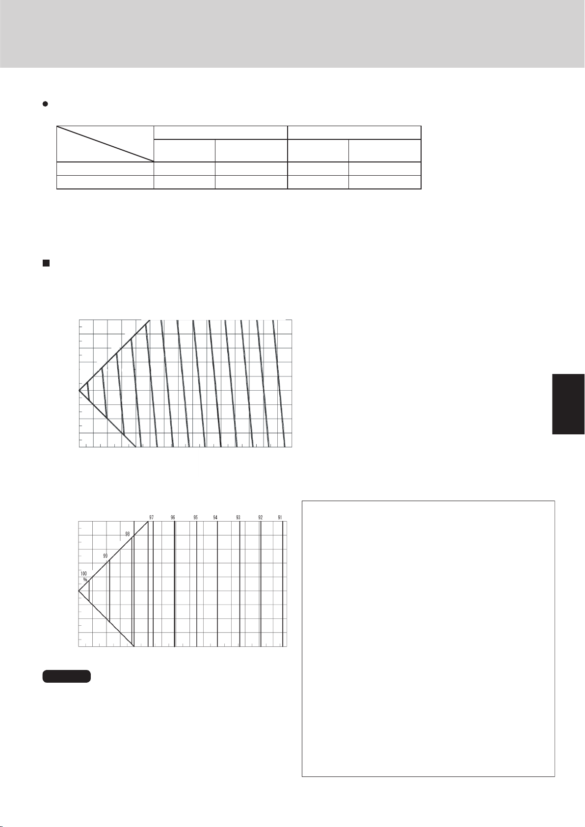
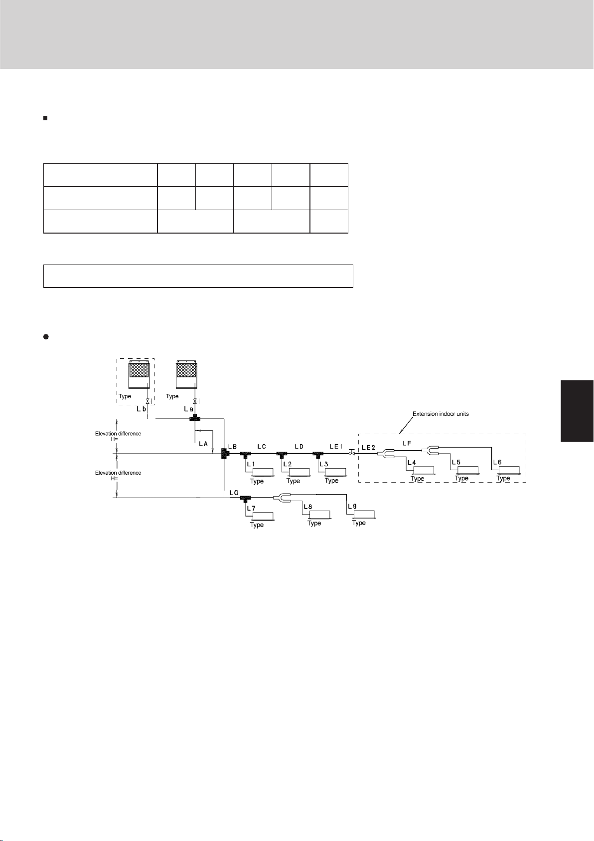
Checking of limit density
The limit density judgment is made based on the room with the
indoor unit having the smallest capacity in the system after extension.
The volume of the room where a type 1852 indoor unit is used
(connected to tubing L9) is calculated as follows:
floor area 166 ft2 × Ceiling height 8.8 ft = 1,410 ft3. From the graph
below, the minimum room volume for 1,222 oz of refrigerant is
4,070 ft3 (floor area 463 ft2). Therefore an opening for ventilation is
required.
<Judgment by calculation>
Total refrigerant charge for the refrigeration equipment (oz)
Smallest room volume of all rooms where indoor units are
installed (ft3)
1,222 (oz)
=
1,410 (ft3)
= 0.86 (oz/ft3) > 0.3 (oz/ft3)
In this case, an opening is required for ventilation.
Always check the gas
density limit for the room in
which the unit is installed.
Checking of limit density
When installing an air conditioner in a room, it is necessary to
ensure that even if the refrigerant gas accidentally leaks out, its
density does not exceed the limit level for that room.
If the density could exceed the limit level, it is necessary to provide
an opening between the unit and the adjacent room, or to install
mechanical ventilation which is interlocked with a leak detector.
(Total refrigerant charged amount: oz)
(Min. indoor volume where the indoor unit is installed: ft.3)
<
Limit density 0.3 (oz/ft.3)
The limit density of refrigerant R410A which is used in this unit is
0.3 oz/ft.3 (ISO 5149).
The shipped outdoor unit comes charged with the amount of refrigerant fixed for each type, so add it to the amount that is charged in the
field. (For the refrigerant charge amount at shipment, refer to the
unit’s nameplate.)
Minimum indoor volume & floor area as against the amount
of refrigerant is roughly as given in the following table.
Page 32

1
2
3
4
5
6
7
8
1
2
3
4
5
6
7
8
15 to 30
°
B
A
B
A
Arrow view
Horizontal
line
View as seen
from arrow
Ball valve
(BV: purchased
separately)
Main tubing
Types of vertical trap specifications
(If only 1 unit is connected, a ball
valve is also needed on this side.)
Indoor unit (1)
(When not using ball valve)
(When using ball valve)
Branch tubing is
directed upward.
(Each unit is
connected to tubing
that is either level or
is directed
downward.)
Main tubing
Indoor unit
More than
8 in
Indoor unit (more than 2 units)
Horizontal
Indoor unit is directed downward
2. System Design
Design of W-2WAY ECO-i SYSTEM Unit Specifications
Installing distribution joint
(1) Refer to “HOW TO ATTACH DISTRIBUTION JOINT”
enclosed with the optional distribution joint kit (APRCHP680BA, CHP1350BA, P160BA, P680BA,
P1350BA).
(2) In order to prevent accumulation of refrigerant oil in
stopped units, if the main tubing is horizontal then
each branch tubing length should be at an angle that
is greater than horizontal. If the main tubing is vertical,
provide a raised starting portion for each branch.
(3) If there are height differences between indoor units
or if branch tubing that follows a distribution joint is
connected to only 1 unit, a trap or ball valve must be
added to that distribution joint. (When adding the ball
valve, locate it within 1.3 ft of the distribution joint.)
(Consult with SANYO separately concerning the ball
valve.)
If a trap or ball valve is not added, do not operate
the system before repairs to a malfunctioning
unit are completed. (The refrigerant oil sent
through the tubing to the malfunctioning unit will
accumulate and may damage the compressor.)
Tube branching methods (horizontal use)
2-22
Page 33

1
2
3
4
5
6
7
8
3. Electrical Wiring
Control wiring
(C) Inter-unit (between outdoor and
indoor units) control wiring
(D) Remote control wiring (E) Control wiring for group control
(F) Inter-outdoor unit control wiring
AWG #18 (0.75 mm2) AWG #18 (0.75 mm2) AWG #18 (0.75 mm2)
AWG #18 (0.75 mm2)
Use shielded wiring* Use shielded wiring Use shielded wiring
Use shielded wiring
Max. 3,280 ft.
Max. 1,640 ft.
Max. 1,640 ft. (Total)
Max. 1,640 ft.
O
utdoor unit
CHDX09053 60 A
CHDX14053 80 A
Time delay fuse or
circuit capacity
(A) Power supply wiring
Indoor unit
Time delay fuse or
(B) Power supply wiring
circuit capacity
K
A, X, T, U
Type
Type
15 A
For field wiring rules, please refer to
your LOCAL ELECTRICAL CODES
For field wiring rules, please refer to
your LOCAL ELECTRICAL CODES
15 A
15 A
D
Design of W-2WAY ECO-i SYSTEM Unit Specifications
3-1. General Precautions on Wiring
(1) Before wiring, confirm the rated voltage of the unit
as shown on its nameplate, then carry out the wiring
closely following the wiring diagram.
(2) Provide a power outlet to be used exclusively for
each unit, and a power supply disconnect and circuit
breaker for overcurrent protection should be provided
in the exclusive line.
(3) To prevent possible hazards from insulation failure,
the unit must be grounded.
(4) Each wiring connection must be done in accordance
with the wiring system diagram. Wrong wiring may
cause the unit to misoperate or become damaged.
(5) Do not allow wiring to touch the refrigerant tubing,
compressor, or any moving parts of the fan.
(6) Unauthorized changes in the internal wiring can be
very dangerous. The manufacturer will accept no re-
3-2. Recommended Wire Length and Wire Diameter for Power Supply System Outdoor unit
sponsibility for any damage or misoperation that occurs
as a result of such unauthorized changes.
(7) Regulations on wire diameters differ from locality to
locality. For field wiring rules, please refer to your LOCAL
ELECTRICAL CODES before beginning.
You must ensure that installation complies with all rel-
evant rules and regulations.
(8) To prevent malfunction of the air conditioner caused by
electrical noise, care must be taken when wiring as follows:
The remote control wiring and the inter-unit control wiring
should be wired apart from the inter-unit power wiring.
Use shielded wires for inter-unit control wiring between
units and ground the shield on both sides.
(9) If the power supply cord of this appliance is damaged,
it must be replaced by a repair shop appointed by the
manufacture, because special purpose tools are required.
NOTE
* With ring-type wire terminal.
2-23
Page 34

1
2
3
4
5
6
7
8
1
2
3
4
5
6
7
8
1
2
3
4
5
6
7
8
3. Electrical Wiring
NOT E
(1) Refer to Section 3-2. “Recommended Wire Length and
Wire Diameter for Power Supply System” for the
explanation of “A,” “B,” “C,” “D,” and “E,” in the above
diagram.
(2) The basic connection diagram of the indoor unit shows
the 7P terminal board, so the terminal boards in your
equipment may differ from the diagram.
(3) Refrigerant Circuit (R.C.) address should be set before
turning the power on.
(4) Regarding the R.C. address setting, refer to Section 5.
Address setting can be executed by remote controller
automatically. Refer to Section 5.
K Type
1(L1) 2(L2)
U2U1
1 2 3 4 5
Power
supply
Inter-unit
control wiring
5P terminal board
1(L1) 2(L2)
Power
supply
U1
Inter-unit
control wiring
U2
Remote
controller
R1
R2
X,A,U,D,T Type
7P terminal board
U2
U1
L2
L1
R2
R1
2
1
U2
U1
4
3
3
4
5
2
1
WHT
Remote
controller
BLK
2
1
2
1
WHT
Remote
controller
Group control:
BLK
2
1
2
1
WHT
Remote
controller
D
A
E
Indoor
unit (No. 4)
Indoor
unit (No. 1)
Indoor
unit (No. 2)
Indoor
unit (No. 3)
C
B
Outdoor unit
INV unit
L1
L2
L3
Ground
Ground
L1
L2
L1
L2
L1
L2
L1
L2
BLK
2
1
2
1
4
3
3
4
5
Outdoor unit
INV unit
Power supply
208 / 230V, 1ø, ~60Hz
Power supply
208 / 230V, 1ø, ~60Hz
Power supply
208 / 230V, 1ø, ~60Hz
Power supply
208 / 230V, 1ø, ~60Hz
Power supply
208 / 230V, 3ø, ~60Hz
Power supply
208 / 230V, 3ø, ~60Hz
B
B
B
Ground
Ground
Ground
Ground
A
L1
L2
L3
Ground
Ground
C
Ground
Ground
Ground
Ground
Ground
F
Ground
D
D
C
Ground
Ground
C
Ground
Inter-outdoor-unit control wiring
U2
U1
L2
L1
R2
R1
U2
U1
L2
L1
R2
R1
U2
U1
L2
L1
R2
R1
3-3. Wiring System Diagrams
Design of W-2WAY ECO-i SYSTEM Unit Specifications
2-24
Page 35

1
2
3
4
5
6
7
8
2-25
Design of W-2WAY ECO-i SYSTEM Unit Specifications
1
2
3
4
5
6
7
8
Outdoor unit Outdoor unit Outdoor unit
Indoor unit Indoor unit Indoor unit Indoor unit
Indoor unit
more than 3.3 ft
more than 3.3 ft
Branch
point
16 or fewer
Indoor unit
Indoor unit Indoor unit Indoor unit
less than 3.3 ft
Indoor unit
Outdoor unit Indoor unit Indoor unit Indoor unit
Indoor unit Indoor unit Indoor unit
Outdoor unit
Indoor unit
NO
NO
Branch point
Outdoor unit Outdoor unit Outdoor unit
Prohibited
Prohibited
Indoor unit Indoor unit Indoor unit Indoor unit Indoor unit
WARNING
CAUTION
3. Electrical Wiring
(1) When linking outdoor units in a network (S-net link system), disconnect the terminal extended from the
short plug (CN003, 2P Black, location: right bottom on the outdoor main control PCB) from all outdoor
units except any one of the outdoor units.
(When shipping: In shorted condition.)
Otherwise the communication of S-net link system is not performed. For a system without link (no con-
nection wiring between outdoor units), do not remove the short plug.
(2) Do not install the inter-unit control wiring in a way that forms a loop. (Fig. 2-1)
(3) Do not install inter-unit control wiring such as star branch
wiring. Star branch wiring causes mis-address setting.
(4) If branching the inter-unit control wiring, the number of branch points should be 16 or fewer. (Branches
less than 3.3 ft are not included in the total branch number.) (Fig. 2-3)
Fig. 2-1
Fig. 2-2
Fig. 2-3
Page 36

1
2
3
4
5
6
7
8
1
2
3
4
5
6
7
8
3. Electrical Wiring
WARNING
Shielded wire
Ground
Ground
Stranded wire
Ring
pressure
terminal
Strip 3/8 in
Wire
Special
washer
Screw
Ring pressure
terminal
Terminal plate
Screw and
Special washe
r
Ring
pressure
terminal
Wire
(5) Use shielded wires for inter-unit control wiring (c)
and ground the shield on both sides, otherwise
misoperation from noise may occur.(Fig. 2-4)
Connect wiring as shown in Section 3-3. “Wiring
System Diagrams.”
Loose wiring may cause
the terminal to overheat or
result in unit malfunction.
A fire hazard may also exist.
Therefore, ensure that all
wiring is tightly connected.
When connecting each power wire to the terminal, follow the
instructions on “How to connect wiring to the terminal” and
fasten the wire securely with the fixing screw of the terminal
plate.
Design of W-2WAY ECO-i SYSTEM Unit Specifications
Fig. 2-4
How to connect wiring to the terminal
For stranded wiring
(1) Cut the wire end with cutting pliers, then strip the insulation
to expose the stranded wiring about 3/8 in and tightly twist
the wire ends.(Fig. 2-5)
(2) Using a Phillips head screwdriver, remove the terminal
screw(s) on the terminal plate.
(3) Using a ring connector fastener or pliers, securely clamp
each stripped wire end with a ring pressure terminal.
(4) Place the ring pressure terminal, and replace and tighten
the removed terminal screw using a screwdriver.
(Fig. 2-6)
Fig. 2-5
Fig. 2-6
2-26
Page 37

1
2
3
4
5
6
7
8
Concealed Duct (High-Static Pressure) Type
4-Way Air Discharge Semi-Concealed Type
3 ft.
3 ft.
3 ft.
3 ft.
3 ft.
W all-Mounted T ype
min.6 in.
Front View
min.
6 in.
min.
6 in.
Ceiling-Mounted T ype
Side vie w
min. 10 in.
min. 2 ft.
Air intake
Air
discharge
min. 10 in.
Ceiling
Wall
Front view
Max. 10 in.
Obstacle
NOTE
The rear of the indoor unit can be installed flush
against the wall.
min. 2 in.
min. 2 in.
min. 3 ft.
Air
intake
Air
discharge
Obstacle
Ceiling
Wall
Wall
Side view
1-Way Air Discharge Semi-Concealed Type
4. Installation Instructions
4. Installation Instructions
4-1. Indoor Unit
AVOID:
areas where leakage of flammable gas may be expected.
places where large amounts of oil mist exist.
direct sunlight.
locations near heat sources which may affect the perform-
ance of the unit.
locations where external air may enter the room directly.
This may cause “sweating” on the air discharge ports,
causing them to spray or drip.
locations where the remote controller will be splashed with
water or affected by dampness or humidity.
installing the remote controller behind curtains or furniture.
locations where high-frequency emissions are generated.
DO:
select an appropriate position from which every corner of
the room can be uniformly cooled.
select a location where the ceiling is strong enough to
support the weight of the unit.
select a location where tubing and drain pipe have the
shortest run to the outdoor unit.
allow room for operation and maintenance as well as unre-
stricted air flow around the unit.
install the unit within the maximum elevation difference
above or below the outdoor unit and within a total tubing
length (L) from the outdoor unit as detailed in Table 2-1.
allow room for mounting the remote controller about 3 ft
off the floor, in an area that is not in direct sunlight nor in
the flow of cool air from the indoor unit.
Design of W-2WAY ECO-i SYSTEM Unit Specifications
Fig. 2-7
Fig. 2-8
Air delivery will be degraded if the distance from the floor to
the ceiling is greater than 10 ft.
NOTE
Fig. 2-9
Fig. 2-10
2-27
Page 38

1
2
3
4
5
6
7
8
1
2
3
4
5
6
7
8
1
2
3
4
5
6
7
8
WARNING
CAUTION
Fig. 2-11
Outdoor
unit
Heat
source
Hot air
Exhaust fan
More than
2 in.
More than
1.7 ft.
* More than 4 in.
* More than 4 in.
* More than 4 in.
Example of installation of 2 units
(When wall height is below 6 ft.)
* However, be sure to ensure a space of 1 ft. or more at
either the right side or the rear of the unit.
74-1/64
35-3/64
35-3/64
36-7/32
37-13/32
35-3/64
7-7/8
3 - 15/16
31-7/64
70-5/64
31-7/64
Design of W-2WAY ECO-i SYSTEM Unit Specifications
4. Installation Instructions
4-2. Indoor Unit
AVOID:
heat sources, exhaust fans, etc.
damp, humid or uneven locations
indoors (no-ventilation location)
DO:
choose a place as cool as possible.
choose a place that is well ventilated.
select a location where tubing and drain pipe have the
shortest run to the outdoor unit.
allow enough room around the unit for air intake/exhaust
and possible maintenance.
Installation Space
Install the outdoor unit where there is enough space for ventilation. Otherwise the unit may not operate properly. Fig. 2-12
shows the minimum space requirement around the outdoor
units when 3 sides are open and only 1 side is shuttered, with
open space above the unit. The mounting base should be
concrete or a similar material that allows for adequate drainage. Make provisions for anchor bolts, platform height, and
other site-specific installation requirements.
Leave space open above the
unit.
Construct louvers or other
openings in the wall, if necessary, to ensure adequate ventilation.
NOTE
Do not do any wiring or tubing within 1 ft of the front panel,
because this space is needed as a servicing space for the
compressor.
Ensure a base height of 4 in or more to ensure that drain-
age water does not accumulate and freeze around the
bottom of the unit.
If installing a drain pan, install the drain pan prior to install-
ing the outdoor unit.
* Make sure there is at least 6 in between the outdoor unit
and the ground.
Also, the direction of the tubing and electrical wiring
should be from the front of the outdoor unit.
Fig. 2-12
Fig. 2-13
Unit: in.
2-28
Page 39

1
2
3
4
5
6
7
8
2-29
Design of W-2WAY ECO-i SYSTEM Unit Specifications
1
2
3
4
5
6
7
8
WARNING
CAUTION
With snow-
(High platform)
Without snow-
proof ducting
proof ducting
(Without platform)
AVOID
Fallen snow
DO
Fig. 2-14
Fig. 2-15
Fig. 2-16
4. Installation Instructions
4-3. Shield for Horizontal Exhaust Discharge
It is necessary to install an air-discharge chamber (field supply) to direct exhaust from the fan horizontally if it is difficult
to provide a minimum space of 7 ft between the air-discharge
outlet and a nearby obstacle. (Fig. 2-14)
In regions with heavy snowfall,
the outdoor unit should be
provided with a solid, raised
platform and snow-proof ducting (field supply).(Fig. 2-15)
4-4. Installing the Outdoor Unit in Heavy Snow Areas
In locations where wind-blown snow can be a problem, snowproof ducting (field supply) should be fitted to the unit and
direct exposure to the wind should be avoided as much as
possible. (Fig. 2-16) The following problems may occur if
proper countermeasures are not taken:
The fan in the outdoor unit may stop running, causing the
unit to be damaged.
There may be no air flow.
The tubing may freeze and burst.
The condenser pressure may drop because of strong
wind, and the indoor unit may freeze.
4-5. Precautions When Installing in Heavy Snow
Areas
a) The platform should be higher than the maximum snow
depth. (Fig. 2-15)
b) The 2 anchoring feet of the outdoor unit should be used
for the platform, and the platform should be installed beneath the air-intake side of the outdoor unit.
c) The platform foundation must be solid and the unit must
d) When installing on a roof subject to strong wind, counter-
be secured with anchor bolts.
measures must be taken to prevent the unit from being
overturned.
Page 40

Design of W-2WAY ECO-i SYSTEM Unit Specifications
1
2
3
4
5
6
7
8
1
2
3
4
5
6
7
8
1
2
3
4
5
6
7
8
33-3/16
2-11/64 15/16
97-29/32
65-53/64 (32-5/64)
35-15/64
(Maximum bracket dimensions)
35-3/64
(Ceiling panel dimensions)
33-3/16
35-15/64
(Maximum bracket dimensions)
35-3/64
(Ceiling panel dimensions)
35-3/64
(Ceiling panel dimensions)
2-11/64 15/16
97-29/32
65-53/64 (32-5/64)
35-3/64
(Ceiling panel dimensions)
Air direction: Front direction Air direction: Right direction
Ceiling panel
Front view Front view Right side view Right side view
Ceiling panel
unit: in.
Note: Can be installed so that the air direction is to the front, right, left or rear direction.
2-11/64 15/16
35-3/64
(Ceiling panel dimensions)
97-29/32
65-53/64 (32-5/64)
Right side view
unit: in.
31-7/64
33-3/16
5-25/32
74-7/32 (2-unit installation:maximum dimensions)
7-7/8
31-7/64
(Installation hole pitch)
33-3/16
36-7/32
(I
nstallation hole pitch)
Front view
Top view
4. Installation Instructions
4-6. Dimensions of Wind Ducting
Reference diagram for air-discharge chamber (field supply)
2-unit installation
2-30
Page 41

1
2
3
4
5
6
7
8
2-31
Design of W-2WAY ECO-i SYSTEM Unit Specifications
1
2
3
4
5
6
7
8
Front view
45-5/16
45-5/16
36-7/64
92-53/64
36-7/64
2
3
2
1
1
97-29/32
65-53/64
36-7/64
45-5/16
(32-5/64)
Air direction:
Front direction
Air direction:
Right direction
Ceiling panel
Ceiling panel
Front view
Right side view
Right side view
Ceiling panel
Front view
Right side view
unit: in.
unit: in.
Note: Can be installed so that the air direction is to the front, right, left or rear direction.
53-55/64
31-17/32
31-17/32 (Air intake duct)
33-3/16 (Air outlet duct)
35-3/64
(Ceiling panel dimensions)
9-13/32
53-55/64
36-7/64
45-5/16
9-13/32
9-13/32
35-3/64
9-13/32 9-13/32
53-55/64
35-3/64
(Ceiling panel dimensions)
32-7/8 32-7/8
9-13/32
9-13/32
35-3/64
(Ceiling panel dimensions)
9-13/32
15/16 15/16
53-55/64
31-17/32
31-17/32
1 pc.
4 pc.
31-17/32
35-3/64 35-3/64
3-15/16 3-15/16
112-63/64
35-3/64
31-7/64
7-7/8
31-17/32
97-29/32
65-53/64
9-29/64 9-29/64
7/82-11/64
45-5/16
36-7/64
31-17/32
7-7/8
31-7/64 31-7/64
35-3/64
36-7/32
37-13/32
2 3 2
2
1
35-3/64
(Ceiling panel dimensions)
31-17/32 (Air intake duct)
33-3/16 (Air outlet duct)
Top (Before installation of snowfall protection duct)
2 3 2
74-1/64
35-3/64
35-3/64
36-7/32
37-13/32
35-3/64
7-7/8
3 - 15/16
31-7/64
70-5/64
31-7/64
4. Installation Instructions
4-7. Dimensions of Wind Ducting
Reference diagram for snow-proof ducting (field supply)
2-unit installation
Page 42

Design of W-2WAY ECO-i SYSTEM Unit Specifications
1
2
3
4
5
6
7
8
1
2
3
4
5
6
7
8
1
2
3
4
5
6
7
8
C D E F
H I
H
I
C
C
G
G
G
6-59/64
5-5/16
4-21/64
3-13/16
4-31/64
2-53
/
64
Insulation
Distribution
Joint
Reducing
Joints
Insulation
Distribution
Joint
Reducing
Joints
Gas tubing Liquid tubing
Insulation
B
F
H I
H
I
G
G
G
B
B
(A)
(A)
(A)
6-57/64
5-5/16
4-21/64
3-13/16
C
C
C
D
D
D
4-31/64
2-53
/
64
E
F
Reducing
Joints
Distribution
Joint
Insulation
( ): Outside dimension
Distribution
Joint
Reducing
Joints
Gas tubing Liquid tubing
4. Installation Instructions
4-8. Optional Distribution Joint Kits
See the installation instructions packaged with the distribution joint kit for the installation procedure.
Table 2-14
Model name Cooling capacity after distribution Remarks
1. APR-CHP680BA 232,000 BTU/h (68.0 kW) or less For outdoor unit
2. APR-CHP1350BA 460,700 BTU/h (135.0 kW) or less For outdoor unit
3. APR-P160BA 76,400 BTU/h (22.4 kW) or less For indoor unit
4. APR-P680BA 232,000 BTU/h (68.0 kW) or less For indoor unit
5. APR-P1350BA 460,700 BTU/h (135.0 kW) or less For indoor unit
■ Tubing size (with thermal insulation)
1. APR-CHP680BA
For outdoor unit (Capacity after distribution joint is 232,000 BTU/h (68.0 kW) or less.)
Example:
Unit: in.
Table 2-15 Size of connection point on each part (Shown are inside diameters of tubing)
Size Part A Part B Part C Part D Part E Part F Part G Part H Part I
(ø34.93) (ø31.75) (ø28.58) (ø25.4) (ø22.22) (ø19.05) (ø15.88) (ø12.7) (ø9.52)
2. APR-CHP1350BA
ø1-3/8" ø1-1/4" ø1-1/8" ø1" ø7/8" ø3/4" ø5/8" ø1/2" ø3/8"
in. (mm)
For outdoor unit (Capacity after distribution joint is greater than 232,000 BTU/h (68.0 kW) and no more than
460,700 BTU/h (135.0 kW).)
Example:
Table 2-16 Size of connection point on each part (Shown are inside diameters of tubing)
Size Part A Part B Part C Part D Part E Part F Part G Part H Part I
in. (mm)
(ø34.93) (ø31.75) (ø28.58) (ø25.4) (ø22.22) (ø19.05) (ø15.88) (ø12.7) (ø9.52)
ø1-3/8" ø1-1/4" ø1-1/8" ø1" ø7/8" ø3/4" ø5/8" ø1/2" ø3/8"
2-32
Unit: in.
Page 43

1
2
3
4
5
6
7
8
2-33
Design of W-2WAY ECO-i SYSTEM Unit Specifications
1
2
3
4
5
6
7
8
4-21/64
3-13/16
4-21/64
3-13/16
2-53/64
2-53/64
Insulation
B
A
D
B
B
C
C
C
D E
A
C
D
E
B
Distribution
Joint
Insulation
Distribution
Joint
Gas tubing Liquid tubing
6-57/64
5-5/16
4-21/64
3-13/16
E
E
F G
F
G
H
B
C
D
E
F
E
B C D
F G H
D C B
E F
4-31/64
2-53/64
Distribution
Joint
Distribution
Joint
Insulation
Insulation
Reducing
Joints
Reducing
Joints
A
A
A
Gas tubing Liquid tubing
6-57/64
5-5/16
4-21/64
3-13/16
H
I
J
C
D
E
F
G
H
4-31/64
2-53/64
G
F
F
H
G
G
Distribution
Joint
Distribution
Joint
Insulation
Insulation
Reducing
Joints
Reducing
Joints
B
CD
B
B
(A)
(A)
(A)
C D
Gas tubing Liquid tubing
( ): Outside dimension
4. Installation Instructions
3. APR-P160BA
Use: For indoor unit (Capacity after distribution joint is 76,400 BTU/h (22.4 kW) or less.)
Example:
Unit: in.
Table 2-17 Size of connection point on each part (Shown are inside diameters of tubing)
Size Part A Part B Part C Part D Part E
(ø19.05) (ø15.88) (ø12.7) (ø9.52) (ø6.35)
4. APR-P680BA
Use: For indoor unit (Capacity after distribution joint is greater than 76,400 BTU/h (22.4 kW) and no more than 232,000 BTU/h (68.0 kW).)
ø3/4" ø5/8" ø1/2" ø3/8" ø1/4"
in. (mm)
Example:
Unit: in.
Table 2-18 Size of connection point on each part (Shown are inside diameters of tubing)
Size Part A Part B Part C Part D Part E Part F Part G Part H
(ø28.58) (ø25.4) (ø22.22) (ø19.05) (ø15.88) (ø12.7) (ø9.52) (ø6.35)
5. APR-P1350BA
Use: For indoor unit (Capacity after distribution joint is greater than 232,000 BTU/h (68.0 kW) and no more than 460,700 BTU/h (135.0 kW).)
ø1-1/8" ø1" ø7/8" ø3/4" ø5/8" ø1/2" ø3/8" ø1/4"
in. (mm)
Example:
Table 2-19 Size of connection point on each part (Shown are inside diameters of tubing)
Size Part A Part B Part C Part D Part E Part F Part G Part H Part I Part J
in. (mm)
(ø34.93) (ø31.75) (ø28.58) (ø25.4) (ø22.22) (ø19.05) (ø15.88) (ø12.7) (ø9.52) (ø6.35)
ø1-3/8" ø1-1/4" ø1-1/8" ø1" ø7/8" ø3/4" ø5/8" ø1/2" ø3/8" ø1/4"
Unit: in.
Page 44

1
2
3
4
5
6
7
8
1
2
3
4
5
6
7
8
1
2
3
4
5
6
7
8
(Positions where anchor bolts are fastened)
31-7/64 (Installation hole pitch)
37-13/32 (Maximum dimensions)
35-3/64 (Ceiling panel dimensions)
36-7/32 (Installation hole pitch)
35-3/64 (Ceiling panel dimensions)
Installation anchor hole (4 – 19/32 × 25/32 oval holes)
(3-15/16)
(3-15/16)
3-29/64
25/32
1-31/32
Washer
Plate leg
Base
Anchor bolts
Vibration insulator
WARNING
CAUTION
1-33/64
19/32
1-31/32
4 – 19/32 25/32 hole
(Detailed view of legs)
Surface where
installation anchor
brackets are
installed
74-1/64 (Ceiling panel dimensions)
70-5/64 (Installation hole pitch)
35-3/64 (Ceiling panel dimensions) 35-3/64 (Ceiling panel dimensions)
35-3/64 (Ceiling panel dimensions)
31-7/64 (Installation hole pitch) 31-7/64 (Installation hole pitch)
36-7/32 (Installation hole pitch)
37-13/32 (Maximum dimensions)
Design of W-2WAY ECO-i SYSTEM Unit Specifications
4. Installation Instructions
4-9. Transporting the Outdoor Unit
When transporting the unit, have it delivered as close to the
installation site as possible without unpacking.
Use a hook for suspending the unit. (Fig. 2-17)
When hoisting the outdoor unit, pass ropes or straps under the bottom plate
as shown in the figure at right. When hoisting, the angle between the rope
and top panel must be 70° or greater so that the rope does not come into
contact with the fan guard.
(Use 2 lengths of rope 25 ft. long or longer.)
When passing the ropes through the square holes of the bottom plate:
Place the rope in the outer edge of the square holes.
Use protective panels or padding at all locations where the rope contacts the
outer casing or other parts to prevent scratching. In particular, use protective
material (such as cloth or cardboard) to prevent the edges of the top panel
from being scratched.
Be careful of the fan.
There is danger of injury if the fan starts to turn during inspection. Be sure to
turn OFF the remote power switch before beginning inspection.
Fig. 2-17
4-10. Installing the Outdoor Unit
(1) Use anchor bolts (M12 or 15/32") or similar to securely anchor the unit in
place. (Fig. 2-18)
(2) Be sure the rubber vibration insulator and platform extend to the inside of
the legs. In addition, the washers used to anchor the unit from the top must
be larger than the installation anchor holes. (Figs. 2-18 and 2-19)
Top view
Unit: in.
2-34
Unit: in.
The vibration insulator, base, or platform must
be large enough to bear the full surface of the
base plate legs.
Fig. 2-18
Fig. 2-19
Unit: in.
Page 45

1
2
3
4
5
6
7
8
2-35
Design of W-2WAY ECO-i SYSTEM Unit Specifications
1
2
3
4
5
6
7
8
Fig. 2-21
Remove 2 screws
Tubing cover
Bottom
Front
Remove 11 panel
screws from front
panel
Use cutting pliers or similar
tool to cut cover out
Fig. 2-20
Indentation
(4 locations)
Slit hole
4. Installation Instructions
4-11. Routing the Tubing
The tubing can be routed out either from the front or from the bottom. (Fig. 2-21)
The connecting valve is contained inside the unit. Therefore, remove the front panel. (Fig. 2-21)
(1) If the tubing is routed out from the front, use cutting pliers or a similar tool to cut out the tubing outlet slit (part indicated by
) from the tubing cover. (Figs. 2-20 and 2-21)
(2) If the tubing is routed out from the bottom, remove the slit
part ( ).
Use a drill bit approximately 13/64 ft dia. to create holes at
the 4 slit hole indentations (openings).
Punch out the slit part ( ).
Be careful not to damage the base plate.
Page 46

1
2
3
4
5
6
7
8
1
2
3
4
5
6
7
8
1
2
3
4
5
6
7
8
WARNING
CAUTION
1
2
3
Yes (ø1" ø1-1/8")
Connection method Supplied parts used?
Gas tubing
Liquid tubing
Balance tube
Brazing
Flare connection
Flare connection
No
No
1
2
3
Refrigerant tubing
Yes (ø3/4" ø7/8")
1
2
3
Connection method Supplied parts used?
Gas tubing
Liquid tubing
Balance tube
Brazing
Flare connection
Flare connection
No
No
1
2
3
Refrigerant tubing
Design of W-2WAY ECO-i SYSTEM Unit Specifications
4. Installation Instructions
4-12. Prepare the Tubing
Material: Use C1220 phosphorous deoxidized copper as described in JIS H3300, “Copper and Copper Alloy Seamless Pipes
and Tubes.” (For tubes that are ø7/8" (ø22.22 mm) or larger, use 1/2H material or H material. For all others use O material.)
Tubing size
Use the tubing size indicated in the table below.
When cutting the tubing, use a tube cutter, and be sure to remove any burrs.
(The same applies to distribution tubing (optional).)
When bending the tubes, bend each tube using a radius that is at least 4 times the outer diameter of the tube.
When bending, use sufficient care to avoid crushing or damaging the tube
For flaring, use a flare tool, and be sure that flaring is performed correctly.
Use sufficient caution during preparation of the tubing. Seal the tube ends by means of caps
or taping to prevent dust, moisture, or other foreign substances from entering the tubes.
Refrigerant tubing (Existing tubing can be used.)
Material O Material 1/2H • H
ø1/4" (ø6.35) t1/32" (0.8) ø7/8" (ø22.22) t5/128" (1.0)
ø3/8" (ø9.52) t1/32" (0.8) ø1" (ø25.4) t5/128" (1.0)
ø1/2" (ø12.7) t1/32" (0.8) ø1-1/8" (ø28.58) t5/128" (1.0)
ø5/8" (ø15.88) t5/128" (1.0) ø1-1/4" (ø31.75) t3/64" (1.1)
ø3/4" (ø19.05) over t5/128" (1.0) ø1-3/8" (ø34.93) over t3/64" (1.15)
Tubing size (in. (mm))
4-13. Connect the Tubing
Use the supplied connector tubing. (See figure below.)
09053 type (10 hp)
14053 type (16 hp)
2-36
Page 47

1
2
3
4
5
6
7
8
2-37
Design of W-2WAY ECO-i SYSTEM Unit Specifications
1
2
3
4
5
6
7
8
4. Installation Instructions
WARNING
CAUTION
Tubing
cover
Bottom
plate
Brazing locations
Field-supply tube
Taping
Remote valve
Nitrogen
Pressure-reducing valve (regulator)
Service port cap
(width 19/32)
(0905 Type) (1405 Type)
Service port cap
(width 19/32”, 43/64”)
Service port cap
(width 19/32)
Flare nut
(ø1/4)
Flare nut
(ø3/8)
Service port cap
(width 19/32)
Valve cap
(width 55/64)
Valve cap
(width 55/64”, 15/16”)
Valve cap
(width 55/64)
Valve cap
(width 55/64)
Service port cap
(width 43/64)
Service port cap
(width 19/32)
Flare nut
(ø1/4)
Flare nut
(ø3/8)
Service port cap
(width 19/32)
Valve cap
(width 15/16)
Valve cap
(width 55/64)
Valve cap
(width 55/64)
Cap tightening torque
* Be careful of the cap sizes. The sizes of the service port cap and valve cap
on the 14053 type liquid tube valves are different from other valve caps.
Use two monkey wrenches, as shown in the figure,
when removing the liquid tube valve flare nut.
1. Do not apply a wrench to the valve cap when removing or
installing the flare nuts. Doing so may damage the valve.
60 – 100 lbs
·
in. (70 – 120 kgf
·
cm)
170 – 220 lbs
·
in. (200 – 250 kgf
·
cm)
Do not apply a monkey wrench
to the hexagonal part.
Do not use two monkey wrenches when
removing or installing the balance tube
flare nut. In particular, do not apply a
monkey wrench to the hexagonal part at
the top of the valve.
(If force is applied to this part,
gas leakage will occur.)
2. If the valve cap is left off for a long period of time, refrigerant
leakage will occur. Therefore, do not leave the valve cap off.
3. Applying refrigerant oil to the flare surface can be effective in
preventing gas leakage, however be sure to use a refrigerant
oil which is suitable for the refrigerant that is used in the system.
(This unit utilizes R410A refrigerant, and the refrigerant oil is
ether oil (synthetic oil). However, hub oil (synthetic oil) can also
be used.)
Refrigerant tube port
Use caulking, putty, or a similar material to fill any gaps at the
refrigerant tube port (
foreign substances from entering the unit.
* Perform this work even if the tubing is routed out in a downward
direction.
Tighten each cap as specified below.
Tightening torque for each cap
) in order to prevent rainwater, dust or
Tubing routed out
through the front side
Tubing routed out
through the bottom
Precautions for brazing
Be sure to replace the air inside the tube with nitrogen to prevent oxide film from forming during the brazing process.
Be sure to use a damp cloth or other means to cool the valve unit during brazing.
Work method
Unit: in.
1. Be sure to use nitrogen. (Oxygen, CO2, and CFC must not be used.)
2. Use a pressure-reducing valve on the nitrogen tank.
3. Do not use agents intended to prevent the formation of oxide film. They will adversely affect the refrigeration oil, and may cause equipment failure.
4. The balance tube is not used if only 1 outdoor unit is installed.
Use the unit in the same conditions as when it was shipped from the factory.
Page 48

Page 49

1
2
3
4
5
6
7
8
Control of W-2WAY ECO-i SYSTEM
Contents
3. Control of W-2WAY ECO-i SYSTEM
1. Main Operating Functions .................................................................................................3-3
1-1. Room Temperature Control ...........................................................................................3-3
1-2. Automatic Control for Heating and Cooling ...................................................................3-4
2. Wireless Remote Controller ..............................................................................................3-5
Optional Controller (Remote Controller) ..........................................................................3-5
How to Use the Wireless Remote Controller.....................................................................3-5
Receiver ............................................................................................................................3-8
RCS-SH80AAB.WL for 4-Way Air Discharge Semi-concealed (X Type) ...........................3-9
RCS-TRP80AAB.WL for 1 Way Air Discharge Semi Concealed (A Type) and
Ceiling-Mounted (T Type) ..........................................3-12
RCS-BH80AAB.WL for Concealed Duct (U Type) and
Concealed Duct High-Static Pressure (D Type) ........3-15
RCS-SH1AAB for Wall-Mounted (K Type) .......................................................................3-21
3. Timer Remote Controller .................................................................................................3-22
Timer Remote Controller/RCS-TM80BG .........................................................................3-22
How to Use the Timer Remote Controller .......................................................................3-22
Names and Operations ...................................................................................................3-23
Setting the Present Time ................................................................................................3-28
Weekly Program Function ...............................................................................................3-29
Outing Function ..............................................................................................................3-34
Sleeping Function ...........................................................................................................3-36
4. System Controller ............................................................................................................3-38
System Controller / SHA-KC64UG ..................................................................................3-38
How to use the system controller ....................................................................................3-39
Functions of buttons ........................................................................................................3-40
Display ............................................................................................................................3-42
How to start group operation ..........................................................................................3-43
How to start collective operation .....................................................................................3-44
How to install the system controller ................................................................................3-45
Electrical wiring ...............................................................................................................3-46
Address switch setting ....................................................................................................3-47
Mode setting ...................................................................................................................3-49
How to perform zone registration ....................................................................................3-50
ZONE registration table ..................................................................................................3-51
How to check overlapping of central address No. ...........................................................3-55
3-1
Page 50

1
2
3
4
5
6
7
8
1
2
3
4
5
6
7
8
1
2
3
4
5
6
7
8
Control of W-2 WAY ECO-i SYSTEM
Contents
5. Simplified Remote Controller ..........................................................................................3-56
Simplified Remote Controller / RCS-KR1AGB ...............................................................3-56
Operation Buttons ...........................................................................................................3-56
Display ............................................................................................................................3-58
Operation ........................................................................................................................3-59
Troubleshooting ...............................................................................................................3-60
Tips for Energy Saving ....................................................................................................3-60
Parts Supplied with Simplified Remote Controller ..........................................................3-61
Simplified Remote Controller Installation Guidelines .....................................................3-61
How to Install the Simplified Remote Controller ..............................................................3-61
How to Wire the Simplified Remote Controller ................................................................3-62
Guidelines for Using 2 Simplified Remote Controllers ....................................................3-63
Remote Controller Test Run Setting................................................................................3-63
6. Remote Sensor .................................................................................................................3-64
Remote Sensor / ART-K45AGB .......................................................................................3-64
Parts Supplied with Remote Sensor ...............................................................................3-64
Remote Sensor Installation Guidelines ...........................................................................3-64
How to Install the Remote Sensor ..................................................................................3-65
How to Wire the Remote Sensor.....................................................................................3-66
Important Information When Using Together with Remote Controller Switch .................3-66
3-2
Page 51

1
2
3
4
5
6
7
8
3-3
Control of W-2WAY ECO-i SYSTEM
1
2
3
4
5
6
7
8
Cooling
Room temperature
Set temperature
–2
+2
+4
(deg)
T
Thermostat
ON ONOFF
Heating
Room temperature
Set temperature
–4
–2
+2
(deg)
T
Thermostat
ON ONOFF
1. Main Operating Functions
1-1. Room Temperature Control
The thermostat is turned ON/OFF according to as shown below.
T = Room temperature - Set temperature
When remote controller sensor
is used
When body sensor is used Room temperature = Temperature detected by the body sensor - Intake shift temperature*
* Intake shift temperature (enabled only during heating)
During heating, a difference in temperature occurs between the top and bottom of a room. This value is set in consideration for
the difference between the temperature detected by the body sensor and the temperature at the bottom of the room.
<Value set for intake shift temperature at time of shipment>: 39°F
Note: The shift temperature can be selected in the range of 32 – 50°F, by using the remote controller simplified setting mode.
Room temperature = Temperature detected by the remote controller sensor
(1) After the thermostat turns ON, it will not turn OFF again as a result of for 5 minutes.
(2) After the thermostat turns OFF, it will not turn ON again for 3 minutes. (It also will not turn ON for 3 minutes after the power
is switched ON.)
(3) The compressor turns OFF if the mode is changed cooling heating (or heating cooling) while the compressor is ON.
(4) If “test run” mode is selected, the thermostat will not turn OFF as a result of for 60 minutes. (The thermostat is forced ON.)
Page 52

1
2
3
4
5
6
7
8
1
2
3
4
5
6
7
8
Shift ed set temp
Shifted set temp
Selected operating mode
Selected operating mode
Remote controller display
–4 deg
–2 deg
+2 deg
+6 deg
+4 deg
+5 deg
–6 deg
Thermostat
ON
ON
OFF
ONOFF ONOFF ONON OFF
OFF
A
B
C
Heating HeatingCooling
Control of W-2 WAY ECO-i SYSTEM
1. Main Operating Functions
1-2. Automatic Control for Heating and Cooling
Automatic Heating/Cooling Control
(1) When operation starts, heating or cooling is selected according to the set temperature and the room temperature.
Room temperature Set temperature + 2 Cooling
Set temperature – 2 < Room temperature Set temperature + 2 Monitoring mode (*1)
Room temperature < Set temperature – 2 Heating
*1: If the difference between the room temperature and set temperature is small when operation starts, the cooling
thermostat remains in standby status (OFF) until the temperature difference increases. When the temperature difference increases, either cooling operation or heating operation is selected. This standby status is known as “monitoring
mode.”
(2) After operation starts in the selected operating mode, the set temperature is automatically shifted by +4°F (cooling opera-
tion) or –4°F (heating operation).
Example: Temperature set on the remote controller is 68°F.
Selected operating mode Shifted set temp. Remote controller display
1 Cooling 72°F 68°F
2 Heating 64°F 68°F
(3) Operating mode changes (heating cooling, cooling heating) which occur during operation as a result of temperature
changes are handled as shown below.
Heating cooling: Room temperature Shifted set temperature (set temperature + 4°F) + 1°F
Cooling heating: Room temperature Shifted set temperature (set temperature – 4°F) – 2°F
Example: Temperature set on the remote controller is 68°F.
Operating mode change Shifted set temp.
1 Heating Cooling 68 + 4 + 1 = 73°F or higher (*2)
2 Cooling Heating 68 – 4 – 2 = 62°F or lower
*2: During heating operation when the body sensor is used, a temperature shift is applied to the intake temperature
(4) Cooling (heating) operation does not change if the room temperature changes from area C A (or A C) within 10
(5) When the heating/cooling change
detected by the sensor, in consideration for the difference in temperature at the top and bottom of the room. (Refer
to the “Room Temperature Control” item.) If this intake shift temperature is 8°F, then the heating cooling change
occurs when the temperature detected by the body sensor is 80°F or higher.
minutes after the compressor turns OFF. (Monitoring mode is excepted.)
occurs, the 4-way valve switches
approximately 30 to 50 seconds
after the compressor turns ON.
3-4
Page 53

Control of W-2WAY ECO-i SYSTEM
1
2
3
4
5
6
7
8
The illustration above pictures the wireless remote control unit after the cover
has been lowered and removed.
I: FLAP bu tton
Q: Slide switch
L: SET button
P: ACL button
(ALL CLEAR)
A: ON/OFF operation button
B: Transmitter
D: Temperature setting buttons
H: A/C SENSOR button
N: VENTILATION button
J: TIMER SET button
O: Remote control sensor
F: FILTER button
K: Time setting buttons
G: ADDRESS button
E: FAN SPEED selector button
M: CL button
C: MODE button
NOTE
2. Wireless Remote Controller
Optional Controller (Remote Controller)
Wireless Remote Controller / RCS-SH80AAB.WL (for X Type) / RCS-TRP80AAB.WL (for A, T Type) / RCSBH80AAB.WL (for U, D Type) / RCS - SH1AAB (for K Type)
How to Use the Wireless Remote Controller
A: ON/OFF operation button This button is for turning the air conditioner on and off.
B: Transmitter When you press the buttons on the wireless remote control unit, the mark appears in the
display to transmit the setting changes to the receiver in the air conditioner.
C: MODE button Use this button to select one of the following five operating modes.
(AUTO) : Used to automatically set cooling or heating operation. Only for single heat pump
type
(HEAT) : Used for normal heating operation. Only for heat pump type
(DRY)
D: Temperature setting buttons ::Press this button to increase the temperature setting.
E: FAN SPEED selector button
(COOL) : Used for normal cooling operation.
(FAN) : Used to run the fan only, without heating or cooling operation.
(AUTO) : The air conditioner automatically decides the fan speeds.
(HI) : High fan speed
(MED) : Medium fan speed
(LO) : Low fan speed
: Used for dehumidifying without changing the room temperature.
Press this button to decrease the temperature setting.
(Temperature range: 62 ~ 80°F)
(Temperature range: 60 ~ 78°F)
(Temperature range: 64 ~ 86°F)
(Temperature range: 64 ~ 86°F)
Continued
3-5
Page 54

1
2
3
4
5
6
7
8
1
2
3
4
5
6
7
8
1
2
3
4
5
6
7
8
CAUTION
Control of W-2WAY ECO-i SYSTEM
2. Wireless Remote Controller
F: FILTER button If a separately installed signal receiver is being employed, this button is used to turn off its
filter lamp. When the filter lamp has lighted, first clean the filter, and then press the FILTER
button to turn off the filter lamp. When a wired remote control unit and wireless remote
control unit are both used, the filter sign on the wired remote control unit will appear. When
this happens, first clean the filter, and then press the FILTER button on one of the remote
control units to turn off the filter sign.
G: ADDRESS button When a multiple number of indoor units that can be operated by the wireless remote
control unit have been installed in the same room with a multi-unit or single-unit installation,
this button enables addresses to be set in order to prevent the sending of signals to the
wrong indoor unit. Each of up to six indoor units can be controlled separately using its own
wireless remote control unit by matching the number of the address switch on the operation
area of the indoor unit and the number used for the address of its remote control unit. (The
indoor units cannot be controlled separately when they are used in a flexible combination
format, simultaneous operation of multi units format or any other such format since they will
all operate at the same time.)
NOTE
H: A/C SENSOR button When you press this button (use a narrow-tipped object such as a ballpoint pen), the
NOTE
I: FLAP button 1. Use this button to set the airflow direction to a specific angle.
When the batteries are replaced, the address setting returns to "ALL", so you must make
the setting again.
indication will disappear on the display. The room temperature is detected by the sensor
which is built into the indoor unit and the air conditioner is controlled accordingly.
If the remote control is located near a heat source, such as a space heater or in direct
sunlight, press the A/C SENSOR button to switch to the sensor on the indoor unit.
The airflow direction is displayed on the remote control unit.
Operation mode
(COOL) or (DRY)
(HEAT) or (FAN)
(AUTO)
Cooling mode:
Heating mode:
Number of airflow direction settings
3
5
3
5
NOTE
(SWEEP)
In the Cool mode and Dry mode, if the flaps are set in a downward
position, condensation may form and drip around the vent.
Do not move the flap with your hands.
This function is available only for models X, A, T and K.
2. Use this button to make the airflow direction sweep up and down automatically.
Press this button several times until the symbol appears on the display.
To stop the swing operation
Press the FLAP button again during the flap swing operation to stop the flap at the desired
position. Then, the airflow can be set from the top position by pressing the FLAP button
again.
3-6
Page 55

1
2
3
4
5
6
7
8
3-7
Control of W-2WAY ECO-i SYSTEM
1
2
3
4
5
6
7
8
Fan and heating Cooling and dryi
ng
2. Wireless Remote Controller
Indicator when swing operation is stopped
During cooling and drying, the flap does not stop at the downward position.
Even if the flap is stopped at the downward position during the swing operation, it does not
stop until it moves to the third position from the top.
NOTE
J: TIMER SET button Use this button while the unit is operating to switch between timer settings.
(OFF Timer)
(OFF Cycle Timer)
(ON Timer)
K: Time setting buttons
L: SET button Use this button to set the timer.
M: CL button Use this button to clear the timer setting.
N: VENTILATION button This is used when a ventilation fan (available commercially) is connected. Pressing the
O: Remote control sensor This detects the temperature around the remote control unit when the remote control unit
P: ACL button (ALL CLEAR) Puts the wireless remote control unit into pre-operation status. This is used after the batter-
Q: Slide switch
This function is available only for models X, A, T and K.
: The air conditioner stops after a preset time elapses.
: The air conditioner always stops after a preset time elapses.
: The air conditioner starts after a preset time elapses.
: Press this button to increase the time.
: Press this button to decrease the time.
VENTILATION button turns the fan on and off. The ventilation fan also turns on and off when
the air conditioner unit is turned on and off. (The display of the remote control unit shows "
" while the ventilation fan is running.)
* If the VENTILATION button is held down for 4 or more seconds when the batteries have
been replaced, " " appears on the display, and the ventilation fan can be used.
position has been selected using the sensor button.
ies have been replaced or when the slide switch setting has been changed.
This switch is for setting the operation mode of the indoor unit and setting the flaps.
NOTE
The wireless remote control unit sends the temperature signal to the air
conditioner regularly at five-minute intervals. If the signal from the wireless
remote control unit stops for more than ten minutes due to the loss of the
wireless remote control unit or other trouble, the air conditioner will switch to
the temperature sensor which is built into the indoor unit and control the room
temperature. In these cases, the temperature around the wireless remote
control unit may differ from the temperature detected at the air conditioner's
position.
When low fan speed is selected and the air conditioner is in cooling opera-
tion at a low outdoor temperature of less than 50°F, the air conditioner may
automatically switch to medium fan speed to prevent freezing.
Page 56

Control of W-2WAY ECO-i SYSTEM
1
2
3
4
5
6
7
8
1
2
3
4
5
6
7
8
1
2
3
4
5
6
7
8
E
B
C
D
A
B C D A
E
E
G
F
A
B
C
D
H
B C D A
X type
K type
A, T type
Separately installed
signal receiver (U, D type)
2. Wireless Remote Controller
Receiver
The signal receivers with the exception of the separately installed signal receiver are mounted on the indoor units.
A: Receiver This section picks up infrared signals from the wireless remote control unit (transmitter).
Indication lamps One of these lamps will blink when trouble has occurred. When an indicator lamp starts
to blink, refer to "Trouble Diagnosis" in TEST RUN SERVICE MANUAL.
B: Operation lamp This lamp lights when the appliance is turned on.
C: Timer lamp This lamp lights when the system is being controlled by the timer.
D: Standby lamp This lamp lights at the following times during heating operations: When operation
has started, when the thermostat has been activated, during defrosting operation.
The lamp blinks when trouble has occurred.
E: Emergency operation button This is used when operation cannot be performed due to trouble with or loss of the
wireless remote control unit.
F: ADDRESS switch This switch is used in order to prevent the sending of signals to the wrong indoor unit
when a multiple number of indoor units that can be operated by the wireless remote
control units have been installed in the same room.
G: SWING button When this button is pressed, the airflow sweeps up and down automatically.
H: FILTER lamp This lamp lights to indicate that it is time to clean the filter.
If 2 beeps are heard, the operation lamp among the indication lamps has lighted and the timer lamp and standby
lamp blink alternately. In cases where heat pump models are used, this indicates a Cooling/Heating mode mismatch
and, as such, operation in the desired mode cannot be performed.
(The same beeps will be heard and the same operation lamps will light when auto cooling/heating has been
selected on a model which does not have the auto cooling/heating function.)
When local operation has been set to disabled because the centralized control mode is established, for instance,
pressing the ON/OFF operation button, MODE button or temperature setting buttons results in the sounding of 5
beeps, and the attempted change in the operation will not be accepted.
3-8
Page 57

1
2
3
4
5
6
7
8
3-9
Control of W-2WAY ECO-i SYSTEM
1
2
3
4
5
6
7
8
2. Wireless Remote Controller
Indoor unit
refrigerant tube side
Indoor unit
drain tube side
Receiver unit
installation position
(Right side of electrical
component box)
Indoor unit electrical
component box
Fig. 3-1
Ceiling panel
screw
Adjustable corner cap
Adjustable corner cap
Fig. 3-2
Remove the packing, twist
the wires together and fasten
them with the cable fastener.
Then replace the packing.
Fig. 3-3
Fig. 3-4
How to Install the Wireless Remote Controller
Receiver
RCS-SH80AAB.WL for 4-Way Air Discharge Semi-
Concealed (X Type)
2-1. Installing the Receiver Unit
The only corner where the receiver unit can be installed is the
one shown in Fig. 3-1. Therefore, consider the direction of the
panel when it is installed on the indoor unit.
(1) Remove the intake grille.
(2) Remove the screws that fasten the adjustable corner cap,
then slide the adjustable corner cap to the side to remove
it. (Fig. 3-2)
(3) The square hole used for the panel wiring is filled with
packing (sponge material) used for insulation.* Remove
the packing, then pass the wiring from the wireless receiver unit through the grill.
Twist the wires together and use a cable fastener to fasten
them and fix with screw, then replace the packing in the
hole as it was before. (Fig. 3-3)
* If this packing is not used, there is danger of condensa-
tion on the wiring. Be sure to replace the packing.
(4) After completing wiring as described in “Wiring the Re-
ceiver Unit” on the next page, twist the wires together and
use a cable fastener to fasten them, leaving a length of
wiring that is long enough to permit removal of the adjustable corner cap.(Fig. 3-3)
(5) Install the receiver unit in the panel. At this time, slide the
receiver unit so that each of the 3 tabs fits into its respective hole. Take care that the wires are not pinched.
(Fig. 3-4)
* Refer to the instruction manual provided with the panel.
NOTE
Do not twist the control wiring together with the power wir-
ing because this may cause a malfunction.
Install a noise filter or take other appropriate action if elec-
trical noise affects the power supply circuit of the unit.
* For wiring and test run procedures, refer to “Wiring the
Receiver Unit” and “Test Run.”
Page 58

1
2
3
4
5
6
7
8
1
2
3
4
5
6
7
8
1
2
3
4
5
6
7
8
2. Wireless Remote Controller
1
1
2
1
3
1
4
6
7
5
Fastening screw
Remote
control unit
Remote
control holder
Parts
Q'ty
Parts
Q'ty
AAA alkaline
battery
Receiver
unit
Tapping screw
5/32” 5/8” ×
5/32” 15/32” ×
Clamp
No.No.
2
2
1
1
2PWHT
CN001
WHT
BLK
Indoor unit
Receiver PCB
Remote controller
Terminal board
WARNING
CAUTION
2-2. Accessories
2-3. Wiring the Receiver Unit
Connection diagram
Control of W-2WAY ECO-i SYSTEM
Connect the wire from the receiver unit to the indoor unit
remote controller terminal board. (The wire has no polarity.)
2-4. Precautions on Simultaneous Installation of
Wired Remote Controller and Wireless Remote
Controller
By installing a wired remote controller, the wireless remote
controller kit can permit dual remote control operation at the
same time.
(Up to 2 units of remote controllers - a wireless kit and a wired
unit - can be installed.)
Dual remote control operation can control 1 or multiple air
conditioners using several remote controllers.
Be sure to determine the correct terminal numbers on
the indoor unit when wiring the remote controller. The
remote controller will be damaged if high voltage (such
as 200 VAC) is applied.
The wireless remote controller kit components cannot
be used for more than 1 indoor unit at a time. (However,
separate receiver units may be used simultaneously.)
When a wireless remote controller kit and a wired re-
mote controller are used simultaneously, assign either
the wireless remote controller or the wired remote
controller as the sub remote controller unit.
3-10
Page 59

1
2
3
4
5
6
7
8
3-11
Control of W-2WAY ECO-i SYSTEM
1
2
3
4
5
6
7
8
CN1
(optional)
(optional)
1
2
1 2
Indoor
unit
(sub)
(main)
Receiver unit
Remote controller
terminal board
Ground
Wireless remote
controller kit
Wired remote
controller
Remote control wiring (field supply)
When 1 indoor unit is operated with 2 remote controllers:
(The indoor unit runs according to which of the remote controllers is assigned as the main or sub unit.)
*
*
* Use field wiring cables with a
cross-sectional area of at least
0.5mm
2
to 2mm2.
* The maximum total length of
crossover cables must be no
longer than 400m.
CN1
(optional)
1 2
1 2
(optional)
Indoor
unit No.1
Indoor
unit No.2
Indoor
unit No.3
Indoor
unit No.4
Receiver
unit
(Main)
(Sub)
Remote controller
terminal board
When several groups of indoor units are operated with 2 remote controllers:
(The remote controller (main or sub unit) can operate with any indoor unit.)
Wireless remote
controller kit
Wired remote
controller
Remote control
wiring among the
control groups
(field supply)
* Use field wiring cables with a
cross-sectional area of at least
0.5mm
2
to 2mm2 .
* The maximum total length of
crossover cables must be no
longer than 200m.
**
Ground
Ground Ground
Ground
Fig. 3-6
Fig. 3-5
Receiver PCB
Receiver unit
cover
ON
123
4
Adjustable
corner cap
S003
Bit 1: OFF ON
2. Wireless Remote Controller
(1) To assign the wired remote controller as the sub unit,
locate the address connector at the rear of the wired
remote controller PCB and disconnect it. Reconnect it to
the sub unit position.
(2) To assign the wireless remote controller as the sub unit,
locate the dip switch [S003] on the wireless receiver unit
PCB. Set the No. 3 switch to the ON position.
AWG#20 to AWG#14
longer than 1320 ft.
AWG#20 to AWG#14
longer than 660 ft.
2-5. How to use the Test Run Setting
1. Set DIP switch [S003] No. 1 on the wireless receiver unit
PCB from OFF to ON.
2. All indicator lamps in the display section blink during test
run operation.
3. No temperature control is available during the test run.
4. After the test run, be sure to reset DIP switch No. 1 back
to the OFF position and check that no indicator lamps
are blinking. Then remount and attach the PCB cover as
before.
NOTE
To avoid placing excessive operating load on the equipment,
use this function only when conducting the test run.
Page 60

1
2
3
4
5
6
7
8
1
2
3
4
5
6
7
8
1
2
3
4
5
6
7
8
Fig. 3-7
Fig. 3-8
Fig. 3-9
Fig. 3-10
Panel
Intake grille
Side panel
Insert into groove on
side below “O” mark.
Vinyl tape
Standard screwdriver
(wrapped with vinyl tape)
Cover
Receiver unit
Clamp
Terminal board
2. Wireless Remote Controller
RCS-TRP80AAB.WL for 1 Way Air Discharge
Semi Concealed (A Type) and Ceiling-Mounted (T
Type)
2-6. Installing the Receiver Unit
(1) To take off the side panel, open the intake grille and re-
move the screw. Then remove the side panel by moving it
toward the front (direction of arrow). (Fig. 3-7)
(2) Wrap the end of a standard (flat) screwdriver blade with
vinyl tape. Then insert the screwdriver blade into the
groove on the side of the cover below the “O” mark, and
pry open the cover. (Fig. 3-8) (Take care not to scratch the
panel.)
(3) Pass the lead wire through the panel, then install the
receiver unit in the panel hole.
(The projections on the receiver unit engage the panel
holes to attach the unit.)
(4) Fasten the receiver lead wire to the fastener that holds
the louver motor wiring. (Fig. 3-9)
(5) Reattach the side panel.
(6) Route the lead wire from the receiver unit along the lou-
ver motor wiring and other wiring and fasten them with a
fastener. (Fig. 3-10)
* Access the hole at the top of the electrical component
box to draw in the wiring.
Control of W-2WAY ECO-i SYSTEM
NOTE
Do not twist the control wiring with the power wiring be-
cause this may cause malfunction.
Install a noise filter or take other appropriate action if elec-
trical noise disturbs the unit's power supply circuit.
* For the wiring and test run procedures, refer to “Wiring
the Receiver Unit” and “Test Run.”
3-12
Page 61

1
2
3
4
5
6
7
8
3-13
Control of W-2WAY ECO-i SYSTEM
1
2
3
4
5
6
7
8
2. Wireless Remote Controller
CN001
2PWHT
WHT
BLK
Indoor unit
Receiver unit
Remote
controller
terminal
board
1
1
1
2
2
Receiver unit
AAA alkaline battery
Remote control
holder
Tapping screw
5/32” × 5/8”
4
5
No. Q'ty No.
Parts
Q'ty
1
2
3
Remote control
unit
Parts
WARNING
CAUTION
2-7. Accessories Supplied with Unit
2-8. Wiring the Receiver Unit
Connection diagram
Connect the provided wire (already connected to the
receiver unit) to the indoor unit remote controller terminal
board. (The wire has no polarity.)
2-9.Precautions on Simultaneous Installation of
Wired Remote Controller and Wireless Remote
Controller
By installing a wired remote controller, the wireless receiver
unit can permit dual remote control operation at the same
time.
(Up to 2 units of remote controllers - a wireless remote controller and a wired remote controller - can be installed.)
Dual remote control operation can control 1 or multiple air
conditioners using several remote controllers.
Be sure to determine the correct terminal numbers on the indoor
unit when wiring the remote controller. The remote controller will
be damaged if high voltage (such as 200 VAC) is applied.
The wireless receiver unit components cannot be used for more
than 1 indoor unit at a time. (However, separate receiver units
may be used simultaneously.)
When a wireless receiver unit and a wired remote controller are
used simultaneously, assign either the wireless remote controller
or the wired remote controller as the sub remote controller unit.
(1) To assign the wired remote controller as the sub unit,
locate the address connector at the rear of the wired
remote controller PCB and disconnect it. Reconnect it to
the sub unit position.
(2) To assign the wireless remote controller as the sub unit,
locate the DIP switch [S003] on the wireless control unit.
Set the No. 3 switch to the ON position.
Page 62

Control of W-2WAY ECO-i SYSTEM
1
2
3
4
5
6
7
8
1
2
3
4
5
6
7
8
1
2
3
4
5
6
7
8
CN1
1 2
1 2
1
2
(main)
(sub)
Indoor
unit
Control unit
Remote controller
terminal board
Ground
Remote control wiring (field supply)
(optional)
(optional)
Wireless receiver unit
Wired remote controller
When 1 indoor unit is operated with 2 remote controllers:
(The indoor unit runs according to which of the remote controllers is assigned as the main or sub unit.)
* Use field wiring cables with a
cross-sectional area of at least
AWG#20 to AWG#14.
* The maximum total length of
crossover cables must be no
longer than 1320 ft.
**
CN1
(optional)
1 2 2
1
2
1
2
1 2
1
2
(optional)
1
Indoor
unit No. 1
Receiver
unit
Ground
Remote controller
terminal board
Indoor
unit No. 2
Indoor
unit No. 3
Indoor
unit No. 4
(main)
(sub)
Remote control
wiring among the
control groups
(field supply)
Wired remote
controller
When several groups of indoor units are operated with 2 remote controllers:
(The remote controller (main or sub unit) can operate with any indoor unit.)
* Use field wiring cables with a
cross-sectional area of at least
AWG#20 to AWG#14.
* The maximum total length of
crossover cables must be no
longer than 660 ft.
* *
Wireless receiver
unit
Ground Ground Ground
Fig. 3-11
Fig. 3-12
S003
Bit 1: OFF ON
2. Wireless Remote Controller
2-10. How to Use the Test Run Setting
1. Set DIP switch [S003] No. 1 on the wireless receiver unit
2. All indicator lamps in the display section blink during test
3. No temperature control is available during the test run.
4. After the test run, be sure to reset DIP switch No. 1 back
PCB from OFF to ON.
run operation.
to the OFF position and check that no indicator lamps
are blinking. Then remount and attach the PCB cover as
before.
NOTE
To avoid placing excessive operating load on the equip-
ment, use this function only when conducting the test run.
The unit does not receive remote controller signals for ap-
proximately 1 minute after the power is turned ON. This is
not a malfunction. (The signals are received, but have no
immediate effect.)
3-14
Page 63

1
2
3
4
5
6
7
8
3-15
Control of W-2WAY ECO-i SYSTEM
1
2
3
4
5
6
7
8
Fig. 3-13
1
3
2
4
6
5
Face plate
Remove
Screws
M4 ×25 or 5/32”×1”
Receiver unit
Spacer
2
(provided 7-7/8”
power cable)
Plate
mounting
Screws
M4 × × 1”25 or 5/32”
Screws
M4 × 1-37/64”× 40 or 5/32”
Wood
screws
1
2
3
4
5
No. Parts
Q'ty
No.
6
7
8
9
1
1
2
Parts Q'ty
4
2
1
1
Separate
receiver unit
Spacer
Wire joints
Clamp
Pattern template
3-47/64” × 2”
2
unit: in
2. Wireless Remote Controller
RCS-BH80AAB.WL for Concealed Duct(U Type) and Concealed Duct High-Static Pressure(D Type)
2-11. Accessories Supplied with Separate Receiver Unit
2-12. Important Information for Installation of 1
Separate Receiver Unit
<Installation location>
Do not install in a location where the air contains oil mist,
such as in a kitchen or factory.
Do not install next to a window, or in any other location
directly exposed to sunlight and outside air.
Do not install nearby devices which can be expected to
produce electrical noise, such as elevators, automatic
doors, and industrial sewing machines.
If the receiver unit is installed near a rapid-start type or
inverter-type fluorescent lamp (a lamp which does not
include a glow lamp), it may not be possible to receive
the wireless remote controller signal in some cases. In
order to prevent interference from fluorescent lamps, leave
a minimum of 6.6 ft between the receiver unit and the
fluorescent lamps, and install the receiver unit in a location
where it can receive the wireless remote controller signal
when the fluorescent lamps are lit.
2-13. How to Install the Separate Receiver Unit
NOTE
To avoid malfunction of the remote controller, do not
assemble or run remote control wiring together with the
power cables, and do not enclose them in the same metal
conduit.
When the power unit induces electrical noise, it is
recommended that a noise filter or the like be installed.
Page 64

1
2
3
4
5
6
7
8
1
2
3
4
5
6
7
8
1
2
3
4
5
6
7
8
Fig. 3-14
Fig. 3-15
Fig. 3-16
Face plate
Notch where remote
controller cord passes
through top case
Remote controller
cord (optional)
Connector
Clamp
5/64”~1/8” mm
1 3
2
4
6
5
Remote controller cord
(optional)
Receiver unit
Clamp
Wood
screws (2)
2. Wireless Remote Controller
For flush mounting into a wall, install the separate receiver
unit in a metal switch box (field supply) that has been
recessed into the wall in advance.
1. Insert a flathead screwdriver or similar tool into the notch,
and remove the face plate.
2. Fix the receiver unit with 2 × M4 or 5/32" screws provided.
Do not overly tighten, and use the provided spacers. If the
receiver unit does not fit in the wall, cut spacers to adjust
the clearance.
3. Connect the receiver unit wiring (2-core cable) with the
cables extended from the indoor unit. (Refer to the section
on receiver unit wiring.)
Be sure to determine the correct terminal numbers on the
indoor unit when wiring the receiver unit.
The remote controller will be damaged if high voltage (such
as 200 VAC) is applied.
4. Reinstall the face plate.
When using exposed mounting for the receiver unit, install
onto a wall where the receiver unit can be attached.
1. Insert a flathead screwdriver or similar tool into the
groove on the bottom of the receiver unit. Pry open with
the screwdriver and remove the lower case. (Fig. 3-14).
2. In order to later pass the receiver wiring out through the
upper case (thin part at the top center), use nippers or a
similar tool to cut a notch in the same size as the remote
controller cord (optional). (Fig. 3-15)
3. Disconnect the wires that were connected to the connector at the time of shipment.
4. Fasten the remote controller cord (optional) at the position shown in Fig. 3-16, using the provided clamp. Then
connect the cord to the receiver connector.
5. Shape the remote controller cord as shown in Fig. 3-16
so that it fits at the top inside the receiver unit, above the
PCB. Then attach the lower case. At this time, bend the
head of the clamp so that it faces sideways.
6. Remove the nameplate and use 2 wood screws to attach
the receiver unit.
7. Use the provided cord clips to fasten the remote controller
cord to the wall.
8. Reattach the nameplate.
If the separate receiver unit is installed on the ceiling, use
the provided ceiling mounting bracket for installation.
Control of W-2WAY ECO-i SYSTEM
3-16
Page 65

1
2
3
4
5
6
7
8
3-17
Control of W-2WAY ECO-i SYSTEM
1
2
3
4
5
6
7
8
Fig. 3-17
Part (B)
Part (A)
Fig. 3-18
Fig. 3-19
2. Wireless Remote Controller
1. Insert a screwdriver or similar tool into the notch at the
bottom to remove the receiver nameplate.
2. Cut a section out of the ceiling along the provided paper
pattern (3 - 47/64" × 2").
3. Pass the wire through the provided mounting bracket and
insert the bracket into the installation hole. (Fig. 3-17)
4. Use bracket parts (A) and (B) to securely grip the ceiling
material. (Fig. 3-18)
5. Connect the receiver wire (2-core) to the wire from the
indoor unit.
(Refer to “Wiring the Receiver Unit.”)
Check the terminal number on the indoor unit before wir-
ing the receiver unit and be sure not to wire incorrectly. (The
unit will be damaged if high voltage, such as 200 VAC, is
applied.)
6. Adjust the provided spacers so that they are several millimeters larger than the thickness of the ceiling material.
Pass the 2 supplied screws (M4 × 40 or 5/32" ×1-37/64" )
through the spacers and tighten them enough to hold the
receiver unit in place.
7. Return parts (A) and (B) through the gap between the
ceiling and receiver unit so that they are contained in the
openings. Then tighten the screws.
Do not tighten the screws excessively. This may result in
damage or deformation of the case.
Tighten to the point where the receiver unit can be moved
slightly by hand. (Fig. 3-19)
8. Reattach the nameplate.
Page 66

1
2
3
4
5
6
7
8
1
2
3
4
5
6
7
8
1
2
3
4
5
6
7
8
2. Wireless Remote Controller
Wire of
receiver
unit (field
supply)
Power wire from
receiver unit
Separate
receiver unit
Connector
Indoor unit
remote controller
terminal board
1
2
1
2
WHT
BLK
Wire of receiver unit
(field supply)
Power wire from
receiver unit
1. Strip the insulation to approximately 35/64”
from the ends of the wires to be connected.
2. Twist together the 2 wires and create a
crimp connection at the wire joint.
3. If a special crimping tool is not used, or if
the connection is soldered, insulate the
wires using insulation tape.
Provided
wire joint
(WHT 2)
Wire joint
CE-1 (provided)
Remote controller cord (optional)
Separate
receiver unit
Indoor unit
remote controller
terminal board
1
2
WHT
BLK
1
2
2-14. Wiring the Separate Receiver Unit
* Use wires that are AWG#20 to AWG#14 in diameter.
* The wiring length must not exceed 1320 ft.
<Flush Mounting>
Connection diagram
Control of W-2WAY ECO-i SYSTEM
<Exposed Mounting>
Connection diagram
Use the remote controller cord (optional) for wiring the
separate receiver unit.
1. For the methods used to install the remote controller cord,
refer to “For flush mounting into a wall, install the separate receiver unit in a metal switch box (field supply) that
has been recessed into the wall in advance” on P. 3-16.
2. When using the remote controller cord (optional), refer to
the instruction manual that came with the cord.
Check the terminal number on the indoor unit before wir-
ing the remote controller and be sure not to wire incorrectly. (The unit will be damaged if high voltage, such as
200 VAC, is applied to it.)
3-18
Page 67

1
2
3
4
5
6
7
8
3-19
Control of W-2WAY ECO-i SYSTEM
1
2
3
4
5
6
7
8
2. Wireless Remote Controller
Separate
receiver unit
(main)
Separate
receiver unit
(sub)
(optional)
Remote controller
terminal board
Wire of the receiver unit (field supply)
Indoor
unit
1
2
1
2
2
1
Ground
1 2
1 2
1 2
1 2
1 21 2
Indoor
unit No. 1
Indoor
unit No. 2
Indoor
unit No. 3
Indoor
unit No. 8
Remote controller
terminal board
Separate
receiver unit
(main)
(optional)
Separate
receiver unit
(sub)
(optional)
Crossover cables of the
receiver unit for the
control groups (field supply)
Ground
Ground Ground Ground
2-15. Important Information for Installation of 2
Separate Receiver Units
When using 2 receiver units to operate 1 or more indoor units
at the same time, follow the procedure below to install them.
Installation method
1. If 2 remote controllers are installed, set one of them as
the “main remote controller” (setting at time of factory
shipment).
2. At the other remote controller, remove the receiver name-
plate and switch the DIP switch to “sub remote controller.”
Under these conditions, the receiver unit functions as the
sub receiver unit.
* The TIMER lamp lights only at the remote controller
that receives the signal.
Basic wiring diagram
* When connecting the wires, be careful not to wire
incorrectly.
(Incorrect wiring will damage the unit.)
Using 2 separate receiver units to control 1 indoor unit:
Using 2 separate receiver units to control a group of multi-
ple indoor units:
* The main and sub receiver units will operate regard-
* Use wires that are AWG#20 to AWG#14 in diameter.
* The wiring length must not exceed 1320 ft.
* Use field wiring cables with a cross-sectional
area of at least AWG#20 to AWG#14.
* The maximum total length of crossover cables
must be no longer than 1320 ft.
less of the indoor unit in which they are installed.
Page 68

1
2
3
4
5
6
7
8
1
2
3
4
5
6
7
8
1
2
3
4
5
6
7
8
2. Wireless Remote Controller
2-16. Test Run Setting
1. Remove the receiver unit face plate, and set the DIP
switch to “Test Run - ON” position.
2. Run the air conditioner using the wireless remote control-
ler by pressing the “ON/OFF” button.
All LEDs (“RUN,” “TIMER” and “STANDBY”) blink during
test run operation.
No temperature control is effective with the wireless re-
mote controller in the “Test Run - ON” position.
To avoid mechanical strain on the air conditioner, do not
use this mode except for conducting a test run.
3. Select any one of the operation modes HEAT, COOL or
FAN for the test run.
* The outdoor unit will not start running for about 3 min-
utes after the power ON button is pressed.
4. After the test run operation, stop the air conditioner using
the wireless remote controller, and then reset the DIP
switch in the receiver unit as it was before. (To prevent
constant test running of the air conditioner, the receiver
unit has a 60-minute off timer function.)
Control of W-2WAY ECO-i SYSTEM
3-20
Page 69

1
2
3
4
5
6
7
8
3-21
Control of W-2WAY ECO-i SYSTEM
1
2
3
4
5
6
7
8
KHX0752 / 0952 / 1252 / 1852
KHX2452
Setting at time of
factory shipment
Setting at time of
factory shipment
Slide No. 3 on SW101
from ON OFF.
Slide No. 3 on SW101
from ON OFF.
CR-KR74GXH56A-0
CR-KR254GXH56A-0
2. Wireless Remote Controller
RCS-SH1AAB for Wall-Mounted (K Type)
2-17. When Using Wireless Remote Controller Instead Of Wired Remote Controller
When the wireless remote controller is to be used, slide the switch on the indoor unit control PCB.
• If this setting is not made, an alarm will occur. (The operation lamp on the display blinks.)
• This setting is not necessary if both the wired remote controller and wireless remote controller are used.
• The location of the switch varies depending on the type of PCB used. Check the model name before making the
setting.
Page 70

1
2
3
4
5
6
7
8
1
2
3
4
5
6
7
8
1
2
3
4
5
6
7
8
3. Timer Remote Controller
15 141617232527
29 26
2830 182122
2024
121 2 5 73 86 9 31104 11 13
Operating buttons
Display
8
10
9
13
11
12
1
3
4
7
2
5
6
Timer Remote Controller/RCS-TM80BG
How to Use the Timer Remote Controller
Control of W-2WAY ECO-i SYSTEM
3-22
Page 71

1
2
3
4
5
6
7
8
3-23
Control of W-2WAY ECO-i SYSTEM
1
2
3
4
5
6
7
8
3. Timer Remote Controller
Names and Operations
Operation Section (Refer to the previous page)
1. Start/Stop button
Pushing this button starts, and pushing again stops the
unit.
2. Operation lamp
The lamp is turned on when an air conditioner is in operation.
This lamp blinks when an error occurs or a protective
device is activated.
3. Mode Select button
Pushing this button to select an operation mode. (AUTO
/HEAT /DRY /COOL /FAN ).
4. Temperature setting buttons
Changing the temperature setting.
5. FAN speed button
Changing the fan speed.
6. Swing/Air direction button *1
Use this button to set the auto swing or air direction to a
specific angle.
7. Unit Select button
When more than one indoor unit is operated by one remote control unit, this button is used to select a unit when
adjusting the air direction.
8. Timer setting buttons
( Weekly Program Function)
9. FILTER reset button
Use this button to reset the filter sign.
When is displayed, press this button after cleaning the
filter.
10. Ventilation button
Use this button when you installed a fan available in the
market. Pressing this button turns on and off the fan.
When turning off the air conditioner, the fan will be also
turned off.
(While the fan is operating, will appear in the display.)
*If is displayed on the LCD of the remote control unit
when pressing the ventilation button, no fans are installed.
11. Inspection button
Do not use this button.
12. Sleeping button
( Sleeping Function)
13. Remote control sensor
Normally, the temperature sensor of the indoor unit is
used to detect the temperature. However, it is also possible to detect the temperature around the remote control
unit.
*1 Do not move the flap (vertical airflow adjustment board)
with your hand.
The flap is automatically directed down when the unit is
stopped.
The flap is directed up during the HEAT standby. The
flap starts swinging after the HEAT standby is cancelled, although the AUTO flap indication on the remote
control unit is displayed during the HEAT standby.
Page 72

1
2
3
4
5
6
7
8
1
2
3
4
5
6
7
8
1
2
3
4
5
6
7
8
3. Timer Remote Controller
Display Section (Refer to the page 3-22)
Control of W-2WAY ECO-i SYSTEM
1. SETTING indication
Appears when the timer program is being set.
2. UNIT indication
Indicates the unit No. of the indoor unit which is selected
with the Unit Select button, or the unit in which an abnormality occurs.
3. TIMER No. indication
Appears when the time program is being set.
4. Timer program
: The indoor unit starts operation at the programmed
time.
: The indoor unit stops operation at the programmed
time.
5. Today’s day of the week
Indicates today’s day of the week.
6. Program schedule indication
Appears under days that are scheduled for program operation.
7. Present time
Displays the present time on a 24-hour clock. Also also,
displays settings in the various setting modes.
8. TIMER OFF indication
Displayed when the timer has been turned OFF.
9. ERROR indication
Displayed when a mistake is made during timer setting.
10. Outing indication ( Outing function)
Appears when the outing function is set.
11. Upper and lower limit indication of the outing function
: Indicates the upper limit of the temperature
: Indicates the lower limit of the temperature
12. Operation Mode indication
Displays the selected operation mode. (AUTO /HEAT
/DRY /COOL /FAN ).
13. Temperature indication
Indicates the set temperature.
14. °F / °C temperature unit indication
15. Remote control sensor indication
Appears when the remote control sensor is used.
16. Centralized control indication
Appears when operated in centralized control. If the
remote control operation is not permitted to the remote
unit, when the Start/Stop button, Mode Select button or
Temperature setting button is pressed, flashes and
rejects the change.
17. Operation mode change control indication
Displays when an operation mode is entered by the remote control unit, while another operation mode has been
already selected. This indicates that the operation mode
cannot be changed.
18. Disabled Feature indication
Displayed if the selected feature was disabled during
installation.
20. Heating standby mode indication
appears when the fan of the indoor unit is stopped or in
low fan speed.
21. / / / Fan mode select indication
The selected fan mode is displayed.
22. SWING indication
Appears while the flap swings.
23. Flap position indication
Indicates the flap position.
24. Filter indication
Appears when filter needs cleaning. Clean the filter.
25. Inspection indication
Appears when the protective device is activated or when
an abnormality occurs.
26. Ventilation indication
Appears when a fan available in the market is installed
and is operating.
27. Oil indication
Appears when the engine oil needs to be changed. (Appears when the gas heat pump air conditioner is used.)
28. Sleeping
Appears during the sleeping function.
29. CAUTION
Appears when the protective device is activated or when
an abnormality occurs.
30. Unit No. indication
Indicates the unit No. of the selected indoor unit.
31. TEST indication
Appears while in test operation.
3-24
Page 73

1
2
3
4
5
6
7
8
3-25
Control of W-2WAY ECO-i SYSTEM
1
2
3
4
5
6
7
8
3. Timer Remote Controller
(with 8 in.
wire)
Remote controller Wood screws Wire joints Operation manual Installation manual
CAUTION
Fig. 3-20
Ground
Connection diagram
Basic Wiring Diagram
Terminal board for
indoor unit remote
controller wiring
Remote controller wiring
(field supply)
Connector
Remote
controller
unit
Power wire from remote
controller unit
Approx.
8 in.
1
2
1
2
W
BK
Shielded wire
INSTALLATION MANUAL FOR TIMER REMOTE CONTROLLER
Accessories for remote controller switch
How to install the remote controller
Do not supply power to the unit or try to operate it until the tubing and wiring to the outdoor unit is
completed.
Do not twist the control wiring with the power wiring or run it in the same metal conduit, because
this may cause malfunction.
Install the remote controller away from sources of electrical noise.
Install wiring correctly(incorrect wiring will damage the equipment).
Install a noise filter or take other appropriate action if electrical noise affects the power supply circuit
of the unit.
When wiring, do not connect the remote controller wires to the adjacent terminal block for the power
wiring. Otherwise, the unit will break down.
Use shielded wires for remote control wiring and ground the shield on indoor unit sides. (Fig. 3-20)
Otherwise misoperation due to noise may occur.
The mounting position for the remote controller should be located in an accessible place for control.
Never cover the remote controller or recess it into the wall.
(1) When you open the decorative cover (Fig. 3-23), you will see 2 gaps under the remote controller.
Insert a coin into these gaps and pry off the back case.
(2) Attach the back case with the 2 wood screws provided. Using a screwdriver, push open the cut-outs on the back case.
These holes are for screws. (Fig. 3-24)
(3) Connect the remote controller wiring (2 wires) correctly to the corresponding terminals in the electrical component box of
the indoor unit.
(4) To finish, fit the back tabs of the case into the remote controller and mount it.
Page 74

1
2
3
4
5
6
7
8
1
2
3
4
5
6
7
8
1
2
3
4
5
6
7
8
3. Timer Remote Controller
Fig. 3-21
Remote controller wiring
Power wire from remote
controller unit
Provided wire joint (white)
Wire joint
(sub)
2P terminal
base for remote
control wiring
Remote controller
(main)
1
Indoor unit
No. 1
: Ground (earth)
Indoor unit
No. 2
Indoor unit
No. 8
Indoor unit
No. 3
Connection wiring
for group control
1
1
1
2
2
2
2
1
2
1
2
Fig. 3-22
RCU. Main/Sub
MainSub
CODE
ITEM
DATA
ITEM
Clock display
12 hours
(AM/PM)
24 hours
RCU. CK
NormalRCU. CK
Room temperature sensor
Main unit RCU
CODE
ITEM
DATA
ITEM
Vent. button YesNo
Temperature unit
o
F
o
C
Use AWG#20 to AWG#16 wires.
Remote controller wiring can be extended to a maximum
of 1640 ft.
(1) Strip the insulation to approximately 35/64" from the ends
of the wires that will be connected.
(2) Twist together the 2 wires and create a crimp connection
at the wire joint.
(3) If a special crimping tool is not used, or if the connection
is soldered, insulate the wires using insulation tape.
Group control using 2 remote controllers
It does not matter which of the 2 remote controllers you
set as the main controller. When using multiple remote
controllers (up to 2 can be used), one serves as the
main remote controller and the other as the sub-remote
controller.
Control of W-2WAY ECO-i SYSTEM
Remote controller setting mode
To set the remote controller main/sub setting or change the sensor, follow the steps below.
Press both and buttons on the remote controller for more than
4 seconds together.
Select CODE No. with buttons.
Change DATA with (TIMER) buttons.
Press . Finally, press .
* DATA is memorized in the RCU. (DATA setting will not be changed even
when the power is turned off.)
* Make sure to set [Normal] for RCU. CK.
Indoor unit setting mode
To select the ventilation setting or change the temperature unit, follow the steps below.
Press + + buttons on the remote controller for more than 4 sec-
onds together.
Select CODE No. with buttons.
Change DATA with (TIMER) buttons.
Press . Finally, press .
* DATA is memorized in the indoor unit. (DATA setting will not be changed
even when the power is turned off.)
To display the sensor temperature:
Press both and buttons on the remote controller for more than 4 seconds together.
Change the sensor address (CODE No.) with buttons.
To display the trouble history:
Select the UNIT No. which you want to call with the button.
Press the button to finish service mode.
Press both and buttons on the remote controller for more than 4 seconds together.
Change the alarm message: buttons
Press the button to finish service mode.
CODE No.
(New) (Old)
3-26
Page 75

1
2
3
4
5
6
7
8
3-27
Control of W-2WAY ECO-i SYSTEM
1
2
3
4
5
6
7
8
Fig. 3-23
Fig. 3-24
5/32
7/64
4-23/32
4-23/32
5/8
1-1/2
11
3/16 × 3/8
53/64
4-13/32
15/16
11/64 × 3/8
1/16
11/64 × 3/8
3/16 × 27/64
1-13/16
3-9/32
4-35/64
3. Timer Remote Controller
Caution when installing the remote controller
*1 Install the remote controller more than 3-3/8" apart from the wall surface.
*2 To install the remote controllers side-by-side, keep the space between each for more than 4-59/64".
*3 To install the remote controllers one above the other, keep the space between each for more than 1".
unit :in.
Page 76

1
2
3
4
5
6
7
8
1
2
3
4
5
6
7
8
1
2
3
4
5
6
7
8
1,3,43,4 2
Control of W-2WAY ECO-i SYSTEM
3. Timer Remote Controller
Setting the Present Time
1. Press and hold for more than 2 seconds to enter in the present
day and time setting mode.
Once you enter in the setting mode, , “ ”(day) and “time” flash.
2. Set “ ” to today’s day of the week.
Press *1 to move “ ” (flashing on the display) in the order of :
Su Mo Tu .... Press to move it in the order of : Su St
Fr ....
*1
While in time setting mode, the temperature setting buttons function as
(changing day) button.
3. Press to change the present “hour” in the range of 0 to 23*2.
Set the present hour and press .
The “hour” digits light up, and the “minute” digits start flashing.
*2
If the clock uses the 12 hours AM/PM setting, the hour is displayed in the range of AM 0 to
11/PM 0 to 11.
4. Press , to change the present “minute” in the range of 0 to 59.
Set the present minute and press . The day and time are set and finishes the setting mode.
Note
• The unit returns to the normal mode if is pressed or there is no operation made for 3 minutes
during the setting. In this case, all the settings in progress will be lost.
• If the present time is invalid, “– – : – –” is displayed.
If the power failure for more than 1 hour occurs, check if the set data of day and time are valid.
3-28
Page 77

1
2
3
4
5
6
7
8
3-29
Control of W-2WAY ECO-i SYSTEM
1
2
3
4
5
6
7
8
3. Timer Remote Controller
1
2
3
4
5
6
Su Mo Tu We Th Fr Sa
31
TIMER No. 1~6
program CHeck
2
Weekly Program Function
Checking Weekly Timer
Set the weekly program assigning a given timer to each day of the week.
Maximum of 6 programs a day and 42 programs a week can be set.
Select the day and the TIMER number you want to program.
Program image diagram
Vertical scale indicates the TIMER No.,
and horizontal scale indicates the day.
* If the day is changed, the TIMER No.
returns to “1”.
TIMER No.
button
Select a section from
the 42 programs.
1. Press to enter the program confirmation mode
“ ” and start setting.
Once you enter the program confirmation mode, the
present day is indicated as TIMER No. “1”.
2. Select the day.
Press and / to move the “ ” horizontally on the day to select.
Press to move “ ” (flashing on the display) in the
order of : Su Mo Tu....
Press to move it in the order of : Su Sa Fr....
“– – : – –” is displayed when the program is not set.
3. Select a Timer number.
Press / to select a TIMER No. from 1 to 6.
Press to move up from 1.
Press to move down from 6.
Page 78

1
2
3
4
5
6
7
8
1
2
3
4
5
6
7
8
1
2
3
4
5
6
7
8
3. Timer Remote Controller
1,2,3,4 4
2,3,4
SET
SET
SET
SET
CANCEL,DEL
normal remote controller
program check
PROGRAM CANCEL
CANCEL,DEL
CANCEL
PROGRAM
SET,CANCEL,DEL
SET,CANCEL
Changing the Program Timer
To set the weekly program, follow the steps below.
1. Select the program you want to set in the program
confirmation mode, and press . The enters the
setting mode of the program currently displayed.
* In the program setting mode, , “hour”,
“minute” and “item” flash on the display.
2. Set the “hour”. (program step 1)
Press / to set the “hour”.
Confirm the “hour” and press . The enters the program changing mode (setting of the “minute”).
3. Set the “minute”. (program step 2)
Press / to set the “minute”.
Confirm the “minute” and press .The unit enters
(the program pattern selection mode).
Control of W-2WAY ECO-i SYSTEM
Program step1
Program
Program step2
Changing hour digits
Changing minute digits
Changing patterns
Selecting copy source
Selecting copy destination
3-30
Page 79

1
2
3
4
5
6
7
8
3-31
Control of W-2WAY ECO-i SYSTEM
1
2
3
4
5
6
7
8
3. Timer Remote Controller
Weekly Program Function (Continued)
4. Set the program pattern.
(program step 3)
There are 4 program patterns.
Pressing / repeats the following display patterns.
Pattern 1
The indoor unit starts operation at the programmed
time.
Pattern 2
The indoor unit stops operation at the programmed
time.
Pattern 3
The indoor unit starts operation at the programmed
time and changes the temperature settings.
Press / to change the temperature setting.
Pattern 1
Pattern 2
Pattern 3
Pattern 4
Pattern 4
The indoor unit changes the temperature setting at
the programmed time.
Press / to change the temperature setting.
Select the program pattern and press . The program timer setting is confirmed and the unit enters the confirmation mode .
Note
If you press during the setting, it returns to the program confirmation mode.
If there is no operation made for 3 minutes during the setting, it returns to the normal mode.
In this case, all the settings in progress will be invalid.
Page 80

1
2
3
4
5
6
7
8
1
2
3
4
5
6
7
8
1
2
3
4
5
6
7
8
3. Timer Remote Controller
435 1 2
Deleting the Program Timer
To delete the program timer setting, follow the steps below.
1. Press to enter the program confirmation mode.
2. Press / to select the day of the program you want to delete.
3. Press / to select a TIMER No. (from 1 to 6).
4. Press to display the program setting mode .
5. Press to delete the program.
Note
After deleting, the unit returns to the program confirmation mode .
If you press during the setting, the unit returns to the program
confirmation mode.
If there is no operation made for 3 minutes during the setting, the unit re-
turns to the normal mode.
Invalidating Program Timer
Control of W-2WAY ECO-i SYSTEM
If you want to adjourn the program operation for more than 1 week, you can
invalidate all the timer settings.
Once the timer settings are invalidated, the program will not be operated until the invalidation is cancelled.
<<How to invalidate the program timer>>
Press and hold for more than 2 seconds.
is displayed and the programs will be invalidated from the next one.
<<How to cancel the program timer invalidation>>
Press and hold for more than 2 seconds.
disappears and the programs will be validated from the next one.
If Power Failure Occurred
If the power recovers in a short time period, the program after the recovered time will be valid.
If the power recovered more than 1 hour after the failure, the present time information will be lost. In this case, the program will
not be operated.
3-32
Page 81

1
2
3
4
5
6
7
8
3-33
Control of W-2WAY ECO-i SYSTEM
1
2
3
4
5
6
7
8
3. Timer Remote Controller
3,51 2,4
Weekly Program Function (Continued)
Duplicating the Program Timer
You can duplicate the preset program by day.
Select the copy source.
1. If is pressed in program checking mode , it enters
the copy mode (Selecting the copy source ) of the program timer.
While in the copy mode of the program timer, and
(day) of the copy source flash on the display.
2. Press / to select the day of the copy source.
Select the copy destination.
3. If is pressed in the mode of selecting the copy source
, it enters the copy mode (Selecting the copy destina-
tion ) of the program timer.
4. Press / to select the day of the copy source.
Then, press to complete copying and return to the
program checking mode.
Note
The program will be overwritten if the preprogrammed day is selected as a copy source.
Before Asking Repair Work
Before asking repair work, please check the followings.
Trouble Possible Cause/Remedy
“ERROR” is displayed when the
minute digits are entered.
The set data is not stored. The stored programs are automatically sorted by the time. Check if the data is stored in the other TIMER No.
Program does not function.
If there is another TIMER No. which has the program of the same time and same day, you cannot overlap the
setting.
Check if the time indication is not “– – : – –”.
When the time is invalid, the program is also invalid.
Check the remote controller prohibition inside.
In that case, the program is invalid.
Page 82

Control of W-2WAY ECO-i SYSTEM
1
2
3
4
5
6
7
8
1
2
3
4
5
6
7
8
1
2
3
4
5
6
7
8
F
F
F
F
3. Timer Remote Controller
Outing Function
Outing function is a function that prevents the room temperature from increasing too much (or decreasing too much) when no
one is in the room.
An air conditioner works automatically if this function is set effective.
General Performance of the Outing Function
COOL / DRY
The air conditioner starts operation when the room tem-
perature increases up to –1°F of the upper limit.
The air conditioner stops operation when the room tem-
perature decreases up to –2°F of the upper limit.
HEAT
The air conditioner starts operation when the room tem-
perature decreases up to +1°F of the lower limit.
The air conditioner stops operation when the room tem-
perature increases up to +2°F of the lower limit.
[Precautions]
The outing control only starts/stops the air conditioner. It does not change the operation mode/temperature setting.
Therefore, the operation mode/temperature needs to be set beforehand so that the outing function turns on the air condition-
er with your desired operation mode/ temperature setting.
If the room temperature rapidly changes, the room temperature may get over the upper or lower limit when the outing func-
tion is activated.
The outing function is invalid during FAN/AUTO operation mode.
The air conditioner's stop order (stated in /above) is valid only when the outing function is operated.
If operated using other remote control unit (or a centralized control device such as a system control), the outing function does
not work.
Outing function upper limit
Room temperature
Room temperature
Outing function Lower limit
3-34
Page 83

1
2
3
4
5
6
7
8
3-35
Control of W-2WAY ECO-i SYSTEM
1
2
3
4
5
6
7
8
2
3
3. Timer Remote Controller
Outing Function (Continued)
Setting the Outing Function
1. Press and hold for more than 2 seconds to display the upper limit temperature
setting screen.
, and the upper limit temperature start flashing.
(The default value of the upper limit temperature is 99 °F.)
2. Press / to select the upper limit temperature and press to fix the
value. The lower limit temperature setting screen is displayed.
3. Press / to select the lower limit temperature, and press to fix the
value. The outing function setting is completed. (The default value of the lower limit
temperature is 50 °F.)
* The unit returns to the normal mode if is pressed or there is no operation made for 3
minutes during the setting. In this case, all the settings in progress will be lost.
Canceling the outing function
Press and hold for more than 2 seconds while the outing function is set.
Outing function indication
Outing function indication Status
Off The outing function is not set.
Flashing The outing function is now being set, or under operation.
Lighting Although the outing function is set, not under operation.
Note
A remote controller loses outing function operation information when it is cut for more than one hour during the outing function
operation by electricity. It reverts from the blackout, and an air conditioner does not drive in outing function when operation is
started. At this time, an air conditioner does not stop at outing function.
Page 84

1
2
3
4
5
6
7
8
1
2
3
4
5
6
7
8
1
2
3
4
5
6
7
8
3. Timer Remote Controller
Sleeping Function
* This function leads you to a comfortable sleep and chang-
es the room temperature during your sleep.
* You can set the off timer every one hour from 1 to 10
hours.
Operating time
Sleeping function
indication
Display of remote control unit (during sleeping function setting)
Display of remote control unit
(during the time setting)
Off time
In case the present time
is 23:00.
Control of W-2WAY ECO-i SYSTEM
When the off time comes:
The indoor unit stops.
* The temperature returns to the setting at the time when
sleeping function operation started.
To cancel the sleeping function operation:
Press .
* The temperature setting remains at the time cancelled.
The following buttons also cancel the sleeping function
operation.
button
Stop the indoor unit after the sleeping function operation
is cancelled.
button
Changes the operation mode after the sleeping function
operation is cancelled.
Sleeping function indication
* If no operation is made for 3 minutes, the time setting
mode will be automatically finished.
Ex. In case of 7 hours timer
1. Press .
Each time the button is pressed, the indication changes in
the following order.
(every one hour)
(Press to stop the time setting.)
2. Press .
The sleeping operation starts.
3-36
Page 85

1
2
3
4
5
6
7
8
3-37
Control of W-2WAY ECO-i SYSTEM
1
2
3
4
5
6
7
8
3. Timer Remote Controller
Sleeping Function (Continued)
If button does not work.
Or if the operation does not start even if is pressed.
Check the following table.
Item Display of the remote control unit
1
(for several seconds).
2
3
The sleeping function operation will be cancelled in the following cases:
1: When the unit is operated to stop or change the temperature setting by the other remote control unit or centralized control device.
2: When the unit is operated to stop or change the temperature setting with the weekly program function / outing function.
3: When the centralized control unit is prohibited from stopping the unit or changing the temperature setting.
“This function is not available” indication lights up
(for several seconds).
Centralized control indication flashes
(for several seconds).
(Lighting/flashing indication)
The Error indication flashes
The clock is not set.
When the operation mode is set to AUTO or FAN, this function is not
available.
The centralized control device is prohibited from starting/ stopping the
unit or change the temperature setting.
Contents
Note
Trouble Possible Cause/Remedy
The temperature setting does not decrease (increase). The temperature over the upper or lower limit or each operation mode
cannot be set.
Operation under the sleeping function does not finish. Note if you change the time after the sleeping function started. The
operation does not finish until it reaches to the set starting time.
Page 86

1
2
3
4
5
6
7
8
1
2
3
4
5
6
7
8
1
2
3
4
5
6
7
8
4. System Controller
System controller / SHA-KC64UG
�
Example of central control with system controller (individually controlled)
New control wiring system (S-net link system)
�
New control wiring system (S-net) allows connection of as many as total of 94 units (64 Indoor unit
+30 Outdoor unit) to a single contorl line (non-polar twin-line main bus).
�
The main bus is twin-core and non-polar for easier wiring.
�
Using concurrently as remote controller, system controller can control maximum up to 64 indoor units (or
groups) individually.
�
The system without remote controller can be formed.
�
Maximum up to 2 system controllers (1 main, 1 sub) can be installed.
�
It can separate the 64 indoor units into 4 zones and control each zone individually.
�
Maximum up to 16 groups can be registered to each zone.
�
Collective control and individual group (unit) control can be performed also.
�
Alarm and operation output for an external collected signal is available (potential free contact) DC24V
Max. 1A.
�
Input terminal for collective operation on / off is available.
Outdoor unit
Remote
controller
System
controller
(main)
System without
Remote controller
Group
control
Outdoor unit
2157_M_I
System
controller
(sub)
Remote
controller
Group
control
Group
control
Remote
controller
Control of W-2WAY ECO-i SYSTEM
3-38
Page 87

1
2
3
4
5
6
7
8
3-39
1
2
3
4
5
6
7
8
Control of W-2WAY ECO-i SYSTEM
4. System Controller
How to use the system controller
A:ALL/ZONE/GR SELECT button
Use this button to select one of following:
ALL: Used for turning all the air conditioners on and off.
ZONE:
GR:
A maximum of four zones and 16 groups (units) in a zone
can be set.
B:ZONE select butoon Use this button to select a zone (1 to 4) to operate individually.
C:GROUP select buttons Use these buttons to select a group (1 to 16) to operate individually.
A:ALL/ZONE/GR
SELECT button
B:ZONE select
button
C:GROUP select
buttons
F:Operation lamp
D:ON button
E:OFF button
G:MODE button
H:Temperature
setting buttons
O:VENTILATION
button
K:CHECK
button
L:CENTRAL
CTRL
button
N:CL button
M:SET button
J:FLAP button
I:FAN SPEED
button
ALL
ZONE2
GR2
UNIT
GR1
UNIT
UNIT
GR1
UNIT
UNIT
UNIT
GR3
UNIT
GR2
UNIT
GR3
UNIT
NOTE
ZONE1
2130_M_I
Used for turning all the air conditioners of each zone on and
off.
Used for turning all the air conditioners of each group on and
off.
Page 88

Control of W-2WAY ECO-i SYSTEM
1
2
3
4
5
6
7
8
1
2
3
4
5
6
7
8
1
2
3
4
5
6
7
8
When the indication is displayed, you cannot change the
mode from and or to or and . To change the
mode, turn off all units once then select the mode again.
D:ON button This button is for turning the selected air conditioner on.
E:OFF button This button is for turning the selected air conditioner off.
F:Operation lamp This lamp lights when the unit is turned on.
G:MODE button Use this button to select one of the following five operations:
(AUTO) : Used to automatically set cooling or heating operation.
Only for heat pump type
(temperature range: 62 ~ 80 °F)
(HEAT) : Used for normal heating operation.
(DRY) : Used for dehumidifying without changing the room temperature.
(COOL) : Used for normal cooling operation.
(FAN) : Used to run the fan only, without heating or cooling operation.
H:Temperature
setting buttons
: Press this button to increase the temperature setting.
: Press this button to decrease the temperature setting.
I:FAN SPEED button
(AUTO) : The air conditioner automatically decides the fan speed.
(HI.) : High fan speed.
(MED.) : Medium fan speed.
(LO.) : Low fan speed.
J:FLAP button 1. Use this button to set the airflow direction to a specific angle.
The airflow direction is displayed on the remote control unit.
• In the cool mode and dry mode, when the flaps are set
in a downward position, condensation may form and drip
around the vent.
• Do not move the flap with your hands.
This function is available only for models X, A and T.
( )
2. Use this button to make the airflow direction sweep up and down
automatically.
Press this button several times until the ( ) symbol appears on
the display.
This function is available only for models X, A, K and T.
1) The flap setting can be performed only for units that have no remote
controllers.
2) In the ALL or ZONE mode, no flap setting can be performed. If
necessary, you should select the GR mode and use the FLAP button.
NOTE
Operation mode
(COOL) or (DRY)
(HEAT) or (FAN)
(AUTO)
Cooling mode:
Heating mode:
Number of airflow direction settings
3
5
3
5
NOTE
Functions of buttons
(Continued)
NOTE
NOTE
( )
Only for heat pump type
(temperature range: 60 ~ 78 °F)
(temperature range: 64 ~ 86 °F)
(temperature range: 64 ~ 86 °F)
4. System Controller
3-40
Page 89

1
2
3
4
5
6
7
8
3-41
1
2
3
4
5
6
7
8
Control of W-2WAY ECO-i SYSTEM
K:CHECK button This button is used only when servicing the air conditioner.
Do not use the CHECK button for normal operation.
L:CENTRAL
CTRL
button Use this button to inhibit individual operation by remote controller as
follows:
1: Individual ON/OFF operation is inhibited.
2: Individual ON/OFF, MODE and Temperature setting operation is
inhibited.
3: Individual MODE and Temperature setting operation is inhibited.
4: Individual MODE operation is inhibited.
No indication: Central control is cleared.
(Individual operation)
M:SET button This button is used for setting indoor unit's address when installing the
air conditioner.
Do not use the SET button for normal operation.
N:CL button Use this button to reset the filter sign .
The air conditioner has the timer for the filter and informs you when the
filter needs cleaning.
O:VENTILATION button Use this button when you installed a fan available in the market.
Pressing this button turns on and off the fan.
When turning off the air conditioner, the fan will also turned off. While
the fan is operating, will appear in the display.
If is displayed when pressing the ventilation button, no fans are
installed.
NOTE
2132_M_I
4. System Controller
Page 90

1
2
3
4
5
6
7
8
1
2
3
4
5
6
7
8
1
2
3
4
5
6
7
8
4. System Controller
When turning on the power switch of the system controller, sign
Control of ECO MULTI SYSTEM
A: When the unit is in the heating standby mode, the indicator appears.
B: The currently selected operation mode is displayed.
C: The currently selected FAN SPEED, Airflow Direction and SWEEP
settings are displayed.
D: This indication appears when the filter needs cleaning.
E:
This indication appears only when an abnormality occurs within a unit.
F: The currently selected mode (ALL, ZONE or GROUP), ZONE number
and GROUP number are displayed.
GROUP number display (no figure: no number registered)
GROUP state display ( : registered group, : currently
selected group)
Operation state display ( : on,
no sign: off,
: alarm)
G :
The currently selected central control mode (1, 2, 3 or 4) is displayed
H:
Lights when any of the air conditioners under the system control is
operating; tuens off when none of the air conditioners under the system
control is operating. Blinks when any conditioner is operating under
abnormal conditions and its protection functionality is working.
I:
When the button is pressed for more than four seconds, the TEST
indicator appears.
J :
This indication appears when the temperature is set.
K :
blinks for a few minutes. While blinking, any controls using the system
controller are inhibited. This is because the system controller is verifying
connected groups.
Description
A
B
C
D
E
F
G
H
I
J
K
2133_M_I
Disp lay
Control of W-2WAY ECO-i SYSTEM
3-42
Page 91

1
2
3
4
5
6
7
8
3-43
1
2
3
4
5
6
7
8
Control of W-2WAY ECO-i SYSTEM
4. System Controller
How to start group operation
To start group operation
The flap setting can be performed only for units that have no remote
controllers.
NOTE
Power Turn the power supply switch on more than 5 hours before starting operation.
1
Press the SELECT button and select GROUP.
2
Select the ZONE No. including the group to be operated by pressing ZONE button.
3
Select the GROUP No. to be operated by pressing GROUP select buttons .
4
Press the ON button.
5
Set the operation mode by pressing the MODE button.
6
Set the desired temperature by pressing one of the temperature setting buttons .
7
Set the desired fan speed by pressing the FAN SPEED button.
8
Set the airflow direction to a specific angle or sweep mode.
9
By pressing , select your desired setting.
Individual: Controls with the remote controller are possble.
Central 1: Individual ON/OFF operation with the remote controller is inhibited.
Central 2: Individual ON/OFF, MODE, and Temp. setting operations with the remote
controller are inhibited.
Central 3: Individual MODE and Temp. setting operations with the remote controller are
inhibited.
Central 4: Individual MODE operation with the remote controller is inhibited.
• Under Central/Individual settings other than listed above,
“CENTRAL
” is displayed.
AUTO Depending on the difference between the temperature setting and the room temperature,
Operation heating and cooling alternate automatically so that a uniform room temperature is maintained.
Stop Confirming the GROUP No. to be selected, press the OFF button.
8
9
1
2
5
6
7
3
Stop
4
2134_M_I
Page 92

1
2
3
4
5
6
7
8
1
2
3
4
5
6
7
8
1
2
3
4
5
6
7
8
4. System Controller
Control of ECO MULTI SYSTEM
How to start collective operation
To start collective operation (ALL or ZONE)
In the ALL or ZONE mode, no flap setting can be performed. If necessary, you
should select the GR mode and use the FLAP button
NOTE
Power Turn the power supply switch on 5 hours or more bofore starting operation.
1
Press the SELECT button and select ALL or ZONE.
In case of ZONE collective operation.
2
Select the ZONE No. to be operated by pressing ZONE button.
3
Press the ON button.
4
Set the operation mode by pressing the MODE button.
5
Set the desired temperature by pressing one of the temperature setting buttons .
6
Set the desired fan speed by pressing the FAN SPEED button.
7
Select the control mode.
Stop Confirming the ZONE No. to be selected or ALL indication, press the OFF button.
7
2
1
5
6
4
Stop
3
2135_M_I
Control of W-2WAY ECO-i SYSTEM
3-44
Page 93

1
2
3
4
5
6
7
8
3-45
1
2
3
4
5
6
7
8
Control of W-2WAY ECO-i SYSTEM
4. System Controller
3
Control of ECO MULTI SYSTEM
■ How to install the system controller
Fig. 3-25
2041_C_I
System
controller
Switch box
(no cover)
M4 × 30 or 5/32” × 1-3/16”
Screws (2)
Flat-top
Screw
Back case
Gap
Coin
2042_M_I
Gap
Fig. 3-26
Do not supply power to the
unit or try to operate it until
the tubing and wiring to the
outdoor unit is completed.
9-1. System Controller Installation
● Do not twist the control
wiring with the power
wiring or run it in the
same metal conduit,
because this may cause
malfunction.
● Install the system controller away from sources
of electrical noise.
● Install a noise filter or
take other appropriate
action if electrical noise
affects the power supply
circuit of the unit.
● If local codes allow, this system controller can be
mounted using a conventional wall box for flush
mounting.
(1) Remove the flat-top screw on the bottom of the
back case. When you open up the decorative
cover, you will see two gaps under the system
controller. Insert a coin into these gaps and
remove the back case. (Figs. 3-25, 3-26)
(2) Connect the wires to terminal base of the system
controller (see next page).
(3) Attach the back case with the 2 × M4 or 5/32” screws
provided.
(4) To finish, fit the back tabs of the back case into
the system controller and mount it using the flattop screw.
CAUTION
Page 94

1
2
3
4
5
6
7
8
1
2
3
4
5
6
7
8
1
2
3
4
5
6
7
8
4. System Controller
How to connect electrical wiring
(1) Connect B1, B2 to indoor PCB T10 connector using
the accessory 6P connector. (with fuse) (*No polarity)
Total wire length is less than 985 ft. and size is
AWG#18.
(2) Connect B5, B6 to indoor unit 2P terminal base.
(*No polarity). Wire size is AWG#18.
Basic wiring
Terminals for remote monitoring
Basic wiring diagram of control wiring
A max. of 64 indoor units and 30 outdoor units can be
connected in 1 system.
Up to 10 system controllers can be connected in 1
system.
B1
Indoor unit PCB
T10
(YEL)
2P terminal base
Indoor unit
System controller
Accessory connctor
Wire joint connection
B2
B3
B4
B5
B6
U1
U2
A1
<Back side of system controller>
A2
A3
A4
A5
A6
B6
B5
B4
B3
B2
B1
Inter-unit
control wiring
System controller
RC1
1-1
RC2 RC3
2-1 3-1
B1:
B2:
B3:
B4:
B5:
B6:
Power supply: DC12V *No polarity
To T10 connector on indoor PCB
Inter-unit control wiring. (Low voltage)
To indoor unit 2P terminal base (U1, U2)
*No polarity
Auxiliary of inter-unit control wiring
Not be used
A1:
A2:
A3: Common input for turning air conditioners on or off.
A4:
A5:
A6:
ON operation state indicator output.
Alarm indicator output.
Common indicator output.
Input for turning off air conditioners concurrently.
Input for turning on air conditioners concurrently.
Fig. 3-27
Fig. 3-28
Electrical wiring
Control of W-2WAY ECO-i SYSTEM
3-46
Page 95

1
2
3
4
5
6
7
8
3-47
1
2
3
4
5
6
7
8
Control of W-2WAY ECO-i SYSTEM
4. System Controller
■ Address switch setting
2046_M_I
1
ON
Main/sub selection switch
OFF: System controller operates as main controller.
ON: System controller operates as sub-controller.
SW1
ALL/ZONE mode selection switch
ALL mode:
All indoor units can be controlled by system controller
ZONE 1, 2, 3, 4 mode:
Indoor units in one of zone 1, 2, 3, or 4 can be controlled
by system controller. All indoor units cannot be set.
ALL mode
ZONE 1 mode
ZONE 2 mode
ZONE 3 mode
ZONE 4 mode
OFF
OFF
ON
OFF
ON
2
OFF
OFF
OFF
ON
ON
3
OFF
4
OFF
ON
ON
ON
ON
5
Central control/Remote control mode selection switch.
OFF: Central control mode.
Individual setting by remote controller can be inhibited by
system controller.
ON: Remote control mode.
Setting by system controller is inhibited by other central
control equipments.
Central control Main/Sub selection switch
(OFF: Main, ON: Sub)
1 When AMY adaptor etc. is used with system controller,
set the switch to ON position.
2 When only one system controller is used, set the switch to
OFF position.
3 Except 1 , when multiple system controllers are used,
set only one system controller to OFF position others to
ON position.
ALL mode system controller to be OFF position.
(recommended)
(Central control) button operation switch
OFF: (Central control) button operation is permitted.
ON : button operation is inhibitted.
*All switches are OFF position at shipment.
OFF
2 3 4
SW1
5 6 7 8
Page 96

1
2
3
4
5
6
7
8
1
2
3
4
5
6
7
8
1
2
3
4
5
6
7
8
2047_M_I
1
ON
Weekly timer input switches.
System controller operation can be set when weekly timer
activates (ON/OFF).
SW2
Incase of Remote control mode, use 1 or 2 .
In case of ZONE 1, 2, 3, 4 mode, ALL, all indoor units means
one of ZONE 1, 2, 3, 4.
*
1
: 1 (Central control 1) means ON/OFF operation cannot
excecute by remote controller.
*2: 2 (Central control 2) means ON/OFF, MODE change.
Temp. setting cannot be excecuted by remote controller.
All OFF
All indoor units to
be 1*
1
All OFF and all
indoor units to be
1*
1
All indoor units to
be 2*
2
All OFF and all
indoor units to be
2*
2
All OFF
No change
Individual control
of all indoor units
to be permitted
Ditto
Ditto
Ditto
All ON
Timer OFF→ON Timer ON→OFF
System controller operation
Switch No.
2
3
4
5
6
1
ON
OFF
ON
OFF
ON
OFF
OFF
OFF
OFF
ON
ON
OFF
OFF
ON
ON
OFF
OFF
OFF
1 32
Auxilaly switch
Must be set to OFF position.
Beep tone switch
OFF: Beep tone when each button is pushed.
ON: No tone when each button is pushed.
Indication switch
Normally set to OFF position.
When set to ON position, indication is not displayed on LCD
of system controller.
*All switches are OFF position at shipment.
OFF
2 3 4
SW2
5 6 7 8
4. System Controller
Control of W-2WAY ECO-i SYSTEM
3-48
Page 97

1
2
3
4
5
6
7
8
3-49
1
2
3
4
5
6
7
8
Control of W-2WAY ECO-i SYSTEM
4. System Controller
Control of ECO MULTI SYSTEM
■ Mode setting
According to function of each system controller, set
SW1 as Fig. 3-29.
(1) Central control/Remote control mode
● Central control mode
System controller is used as central control equipment.
Individual setting by remote controller can be
inhibitted by system controller
● Remote control mode
System controller is used as remote controller.
Setting by system controller is inhibitted by other
central control equipments.
(2) ALL/ZONE mode
● ALL mode
All indoor units can be controlled by system controller.
● ZONE mode
Indoor units in one of ZONE 1, 2, 3 or 4 can be
controlled by system controller
(3) Function of system controller is 10 types accord-
ing to combination of central control/remote
control mode and ALL/ZONE mode setting as the
table 9-1.
(4) Stick the system controller unit label in a con-
spicuous position.
Table 9-1
Central control Remote control
ALL 1. ALL/Central 6. ALL/Remote
ZONE1 2. ZONE1/Central 7. ZONE1/Remote
ZONE2 3. ZONE2/Central 8. ZONE2/Remote
ZONE3 4. ZONE3/Central 9. ZONE3/Remote
ZONE4 5. ZONE4/Central 10. ZONE4/Remote
2048_M_I
2
ON
OFF
3 4 5 6
ALL
central control
2
ON
OFF
3 4 5 6
ALL
remote control
Inter-unit control wiring
2
ON
OFF
3 4 5 6
ZONE1
central control
2
ON
OFF
3 4 5 6
1
ZONE1
remote control
2 16
ZONE1
central control
address 1-16
2
ON
OFF
3 4 5 6
ZONE2
central control
2
ON
OFF
3 4 5 6
17
ZONE2
remote control
18 32
ZONE2
central control
address 17-32
2
ON
OFF
3 4 5 6
ZONE3
central control
2
ON
OFF
3 4 5 6
33
ZONE3
remote control
34 48
ZONE3
central control
address 33-48
2
ON
OFF
3 4 5 6
ZONE4
central control
2
ON
OFF
3 4 5 6
49
ZONE4
remote control
50 64
ZONE4
central control
address 49-64
Central control
mode
Remote control
mode
Fig. 3-29
Page 98

Control of W-2WAY ECO-i SYSTEM
1
2
3
4
5
6
7
8
1
2
3
4
5
6
7
8
1
2
3
4
5
6
7
8
Control of ECO MULTI SYSTEM
■ How to perform zone registration
To operate the system controller properly, zone registration is required after finishing the test run (and after
setting all indoor unit addresses) using one of the following methods.
(a) Zone registration using the remote controller (RCS-TM80BG)
Refer to page 3-52
(b) Zone registration using the system controller (SHA-KC64UG)
Refer to page 3-53
(c) Automatic zone registration using the system controller (SHA-KC64UG)
Refer to page 3-54
For methods (a) and (b), you should make a zone registration table manually before performing the registration as shown on the next page.
For method (c), zone registration is executed automatically, proceeding from small indoor unit address and
small central addresses to larger numbers in numerical order. For example:
NOTE 1. An indoor unit address is assigned to each indoor unit during automatic address opera-
tion. Each indoor unit address combines an R.C. address and indoor unit number as
follows:
This address is displayed on remote controller for UNIT No. when the UNIT button is
pressed.
2. The central address represents the zone and group number. These addressed are
assigned in ascending numerical order.
Central address 1 2 3 4 5 6
ZONE–group 1-1 1-2 1-3 1-4 1-5 1-6
Indoor unit address 1-1 1-2 2-1 2-2 2-3 3-1
2084_M_I
: Indoor unit address (UNIT No.)1 – 1
Indoor unit No.
Refrigerant circuit No. (R.C. address)
4. System Controller
3-50
Page 99

1
2
3
4
5
6
7
8
3-51
1
2
3
4
5
6
7
8
Control of W-2WAY ECO-i SYSTEM
4. System Controller
3
Control of ECO MULTI SYSTEM
ZONE GROUP
Central
address
Indoor unit
address
(UNIT No.)
Indoor unit
address
(UNIT No.)
1
2
3
4
5
6
7
8
9
10
11
12
13
14
15
16
1
2
3
4
5
6
7
8
9
10
11
12
13
14
15
16
1
2
3
4
1
2
3
4
5
6
7
8
9
10
11
12
13
14
15
16
17
18
19
20
21
22
23
24
25
26
27
28
29
30
31
32
Unit location ZONE GROUP
Central
address
1
2
3
4
5
6
7
8
9
10
11
12
13
14
15
16
1
2
3
4
5
6
7
8
9
10
11
12
13
14
15
16
33
34
35
36
37
38
39
40
41
42
43
44
45
46
47
48
49
50
51
52
53
54
55
56
57
58
59
60
61
62
63
64
Unit location
■ ZONE registration table
NOTE 1. Assign indoor unit addresses to the desired positions (central addresses)
manually.
2. For group control, only the main indoor unit should be assigned.
Sub indoor units cannot be assigned.
Page 100

1
2
3
4
5
6
7
8
1
2
3
4
5
6
7
8
1
2
3
4
5
6
7
8
4. System Controller
Control of ECO MULTI SYSTEM
NOTE
NOTE
In case of group control “ALL” instead of “UNIT No.”
will flash on the display. Select the main indoor unit
address by pressing the button once.
(4) Set CODE No. to 03 using the and
( ) buttons.
The CODE No. 03 must be selected to perform zone
registration using the remote controller.
(5) Set the Central address which you want to assign
to the indoor unit address using the and
( ) buttons according to the zone
registration table.
(6) Press the button. The CODE No. and Central
address changes from flashing to ON state. If you
make mistake, then press the button and
reset the central address.
(7) Press the button to finish zone registration.
NOTE
Fig. 3-30
2049_M_I
2050_M_I
For example, in this case
Indoor unit address: 1–8
Central address : 17 (ZONE 2, GROUP 1)
Fig. 3-31
(a) Zone registration using the remote controller
(RCS-TM80BG)
(Determination of central address)
● In this case, after confirming which indoor unit is
connected to the remote controller and that the air
conditioner in the OFF state, you set the central
addresses one at a time.
● If the system has no remote controller, connect a
remote controller to the system temporarily. Then
follow this procedure.
The indoor unit address must already have been set
before performing zone registration. If necessary, refer
to the Installation Manual supplied with the outdoor
unit.
(1) Press the and buttons at the same time
of the remote controller for more than 4 seconds.
(2) Do not press buttton.
(3) Once in this mode, the UNIT No., CODE No., No.
of SET DATA and indications will flash on
the display as shown Fig. 3-30.
Control of W-2WAY ECO-i SYSTEM
3-52
 Loading...