

Page 1
FILE NO.
Service Manual
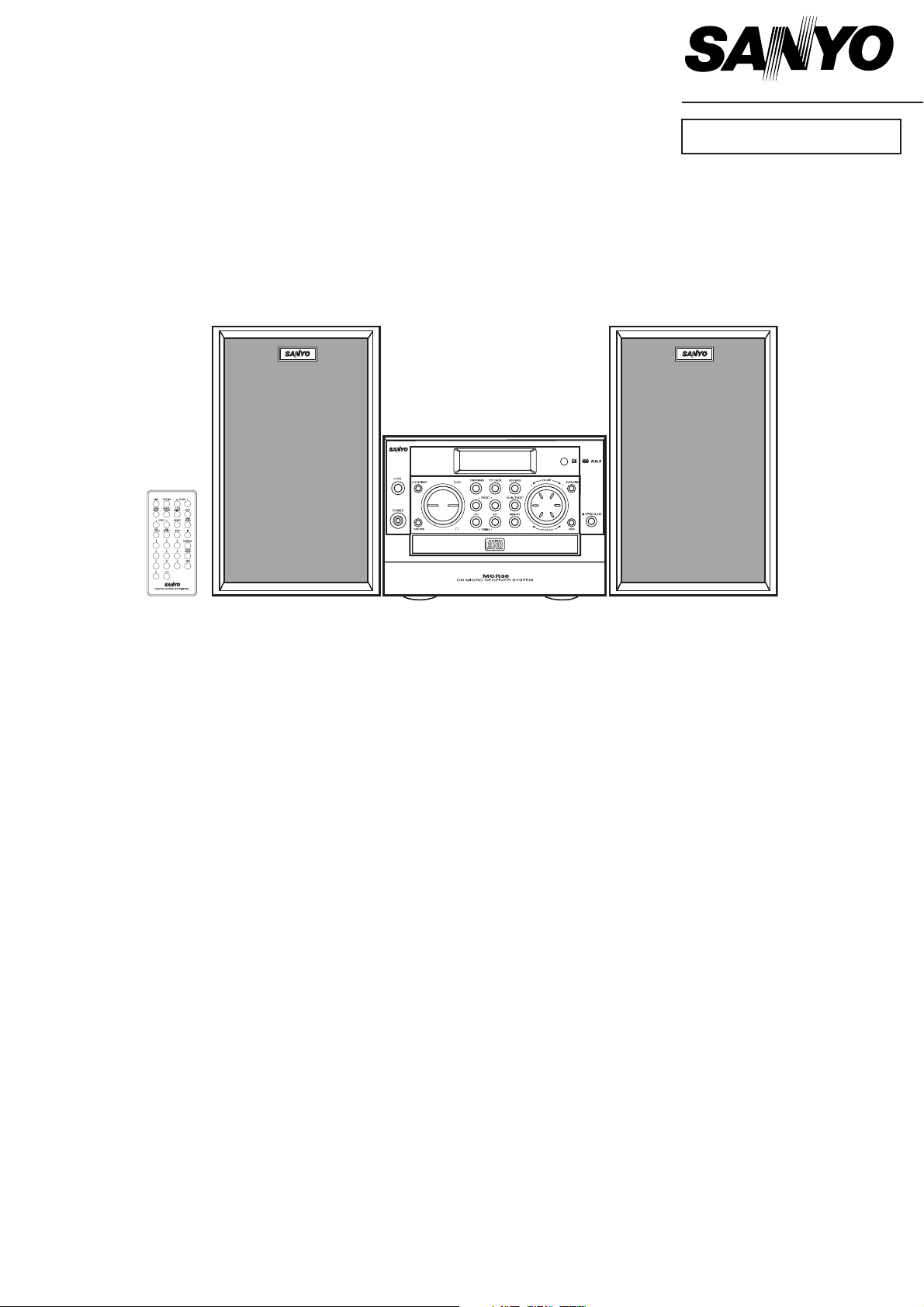
Micro Component System
DC-MCR30
(XE)
CONTENTS
Specifications ................................................................... 1
Laser beam safety precaution .......................................... 1
Tuner adjustment ............................................................. 2
Block diagram .................................................................. 3
Exploded view (cabinet and chassis) ............................... 4
Parts list ........................................................................... 5
Exploded view (CD mechanism) and Parts List ............... 7
Wiring connection ............................................................ 8
IC block diagram and description ..................................... 9
Schematic diagram(Main) ................................................ 12
Schematic diagram(CD) ................................................... 14
Wiring diagram (Main , CD and Speaker) ........................ 16
Wiring diagram (KEY and Phone) .................................... 18
Wiring diagram (Display and Motor) ................................ rear
PRODUCT CODE No.
129 640 00
REFERENCE No. SM5810320
Page 2
SPECIFICATIONS
CD player
Channels:
2 - channel stereo
Sampling frequency:
44.1 kHz
Pick-up:
Optical 3-beam semiconductor laser
Laser output:
0.6 mW (Continuous wave max.)
Wave length:
790 nm
Wow/flutter:
Below measurable limits
Tuner
Reception frequency:
FM: 87.5 - 108 MHz
AM: 522 - 1611 kHz
General
Output power:
20 W x 2 (at 4 ohms, 10% distortion)
Input
AUX IN: 400 mV/50k ohms
Outputs
SPEAKERS: 4 ohms
PHONES: 8 - 32 ohms
Power requirements:
AC 230V, 50 Hz
Power consumption:
45 W
Dimensions:
190(W) x 150(H) x 323(D) mm
Weight:
4.2 kg
Speaker systems (magnetic shield)
Type:
2 way bass reflex
Unit used:
Woofer: 10 cm cone type
Tweeters:2.5 cm balance
Maximum power-handling capacity:
40 W (peak)
Nominal impedance:
4 ohms
Dimensions:
160(W) x 260(H) x 216(D) mm
Weight:
2.2 kg (per speaker)
This is a basic specifications.
Specifications subject to change without notice.
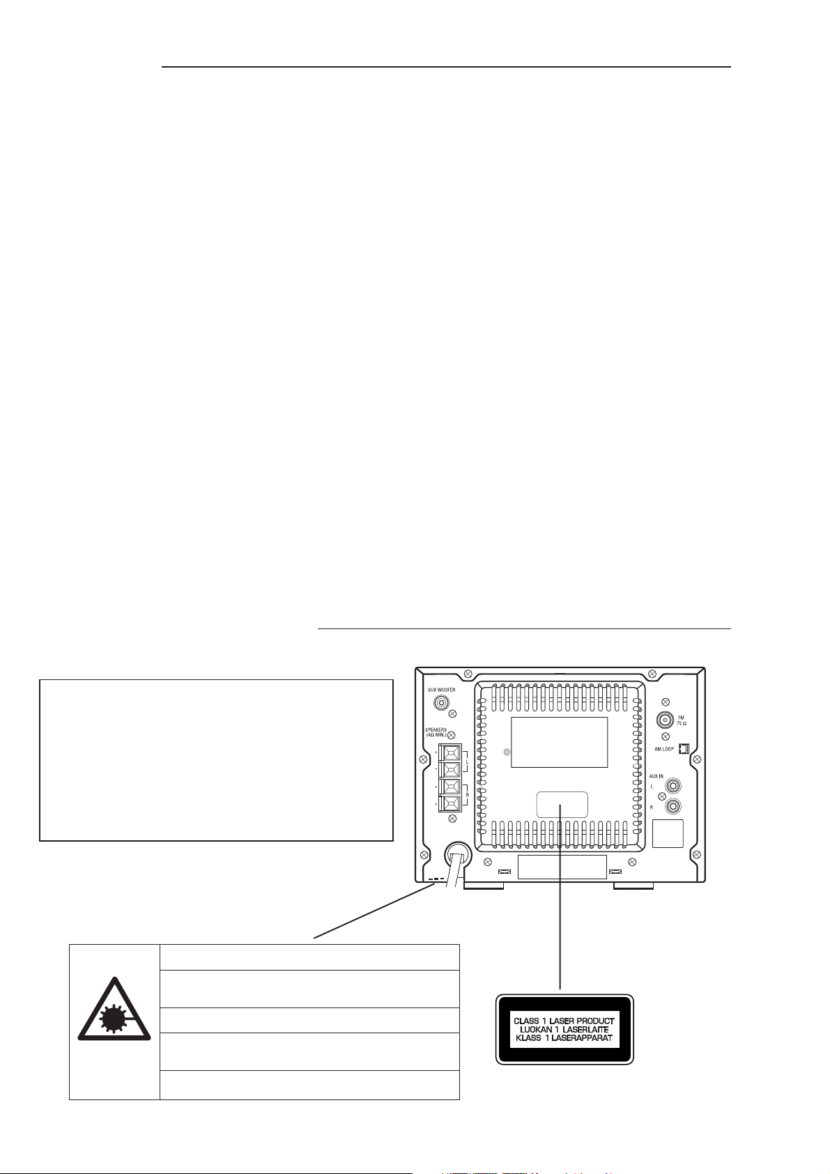
LASER BEAM SAFETY PRECAUTION
• Pickup that emits a laser beam is used on this CD section.
CAUTION :
USE OF CONTROLS OR ADJUSTMENTS OR
PERFORMANCE OF PROCEDURES OTHER
THAN THOSE SPECIFIED HEREIN MAY RESULT
IN HAZARDOUS RADIATION EXPOSURE.
LASER OUTPUT................ 0.6 mW Max. (CW)
WAVE LENGTH ................. 790 nm
CAUTION – INVISIBLE LASER RADIATION WHEN OPEN AND
INTERLOCKS DEFEATED. AVOID EXPOSURE TO BEAM.
ADVARSEL – USYNLIG LASER STRÅLING VED ÅBNING, NÅR
SIKKERHEDSAFBRYDERE ER UDE AF FUNKTION, UNDGÅ UDS ÆTTELSE
FOR STRÅLING.
VARNING – OSYNLIG LASER STRÅLNING NÄR DENNA DEL ÄR ÖPPNAD
OCH SPÄRR ÄR URKOPPLAD. STRÅLEN ÄR FARLIG.
VORSICHT – UNSICHTBARE LASERSTRAHLUNG TRITT AUS, WENN
DECKEL GEÖFFNET UND WENN SICHERHEITSVERRIEGELUNG
ÜBERBRÜCKT IST. NICHT, DEM STRAHL AUSSETZEN.
VARO – AVATTAESSA JA SUOJALUKITUS OHITETTAESSA OLET ALTTIINA
NÄKYMÄTTÖMÄLLE LASERSÄTEILYLLE. ÄLÄ KATSO SÄTEESEEN.
- 1 -
Page 3
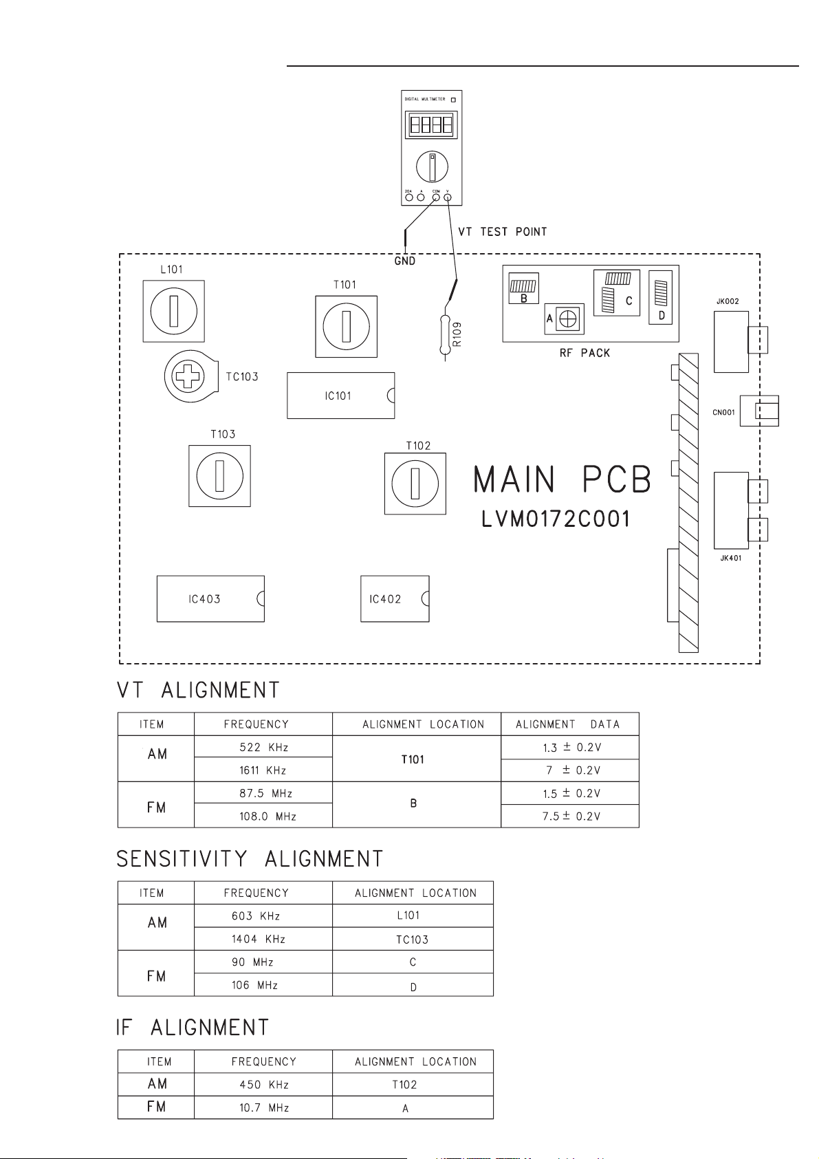
TUNER ADJUSTMENTS
- 2 -
Page 4
- 3 -
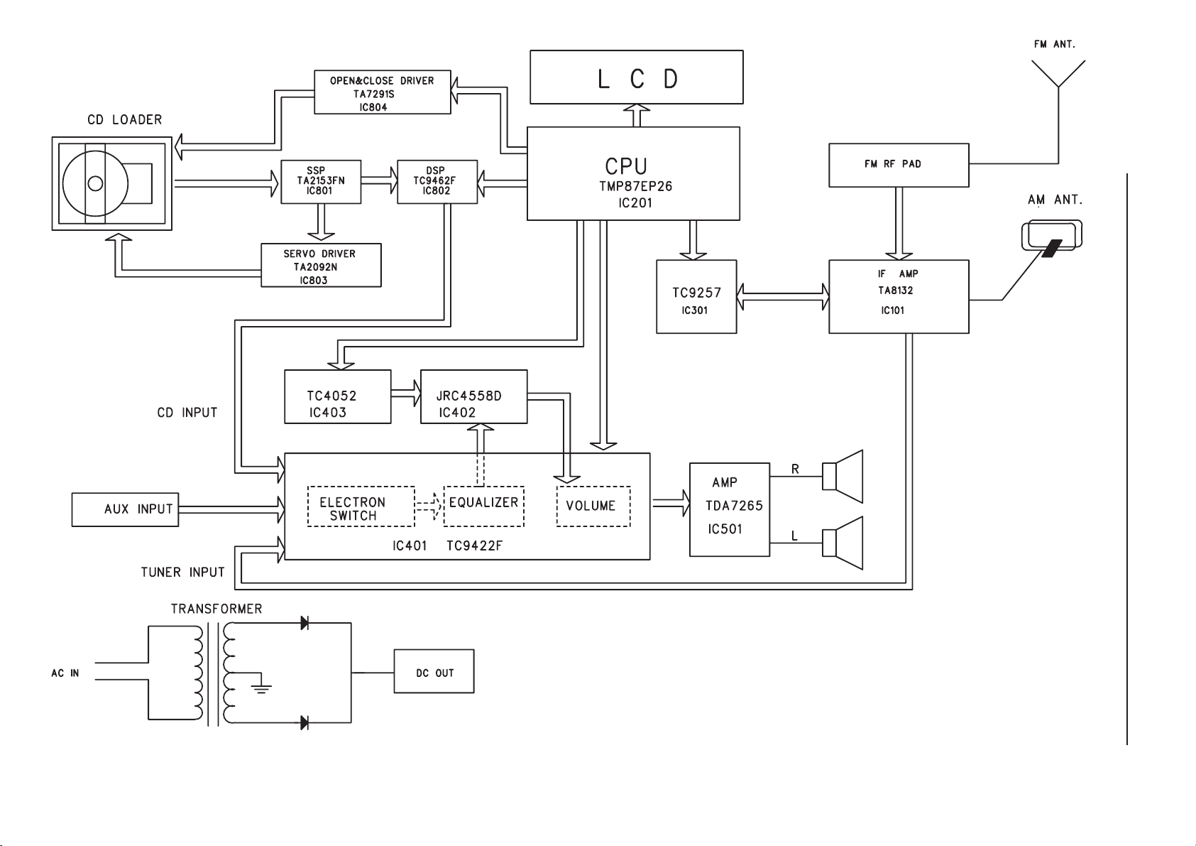
BLOCK DIAGRAM
Page 5
1
2
3
5
6
7
8
10
11
12
14
19
55
56
60
57
58
22
Y12
Y13
Y14
Y16
Y16
Y18
Y17
Y19
Y20
Y20
Y20
Y20
Y20
Y20
Y15
Y15
23
24
28
20
16
15
54
16
51
52
53
18
17
13
72
73
74
71
77
78
4
Y01
Y03
Y02
Y02
Y04
Y05
Y05
Y11
Y06
Y07
Y07
Y08
Y09
Y09
Y10
IC501
Q901
Y10
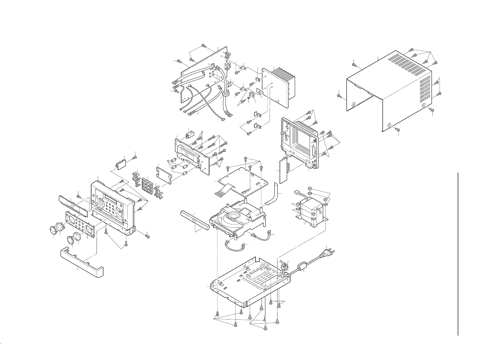
EXPLODED VIEW(CABINET & CHASSIS)
- 4 -
Page 6

PARTS LIST
PRODUCT SAFETY NOTICE
EACH PRECAUTION IN THIS MANUAL SHOULD BE FOLLOWED DURING SERVICING. COMPONENTS IDENTIFIED WITH
!!
!
THE IEC SYMBOL
CAN OF SPECIAL SIGNIFICANCE. WHEN REPLACING A COMPONENT IDENTIFIED , USE ONLY THE REPLACEMENT
PARTS DESIGNATED, OR PARTS WITH THE SAME RATINGS OF RESISTANCE, WATTAGE OR VOLTAGE THAT ARE
DESIGNATED IN THE PARTS LIST IN THIS MANUAL. LEAKAGE-CURRENT OR RESISTANCE MEASUREMENTS MUST
BE MADE TO DETERMINE THAT EXPOSED PARTS ARE ACCEPTABLY INSULATED FROM THE SUPPLY CIRCUIT
BEFORE RETURNING THE PRODUCT TO THE CUSTOMER.
CAUTION : Regular type resistors and capacitors are not listed. To know those values, refer to the schematic diagram.
IN THE PARTS LIST AND THE SCHEMATIC DIAGRAM DESIGNATE COMPONENTS IN WHICH SAFETY
Regular type resistors are less than 1/4W carbon type and chip resistors.
Regular type capacitors are less than 50V and less than 1000µF of Ceramic type and Electrolytic type.
PACKING & ACCESSORIES
REF.NO. PART NO. DESCRIPTION
645 056 3867 CARTON CASE,W/SPK
645 056 3881 POLYFOAM LEFT,MAIN LEFT
645 056 3898 POLYFOAM RIGHT,MAIN RIGHT
645 048 7774 POLYBAG,FOR PWR CORD
645 048 7781 POLYBAG,FOR I/B
645 056 3911 POLYBAG,FOR MAIN UNIT
645 056 4291 INSTRUCTION MANUAL
645 056 3683 MAIN SPK BOX
645 056 3218 REMOCON
645 056 4192 FM ANT
645 056 4208 LOOP ANT ASSY,6 TURN
CABINET & CHASSIS
REF.NO. PART NO. DESCRIPTION
1 645 056 3263 DEC BASE COVER
2 645 056 3393 KNOB PLAY
3 645 056 3478 KNOB LENS
4 645 056 3430 KNOB VOLUME
5 645 056 3485 VOLUME LENS
6 645 056 3270 DEC PANEL
7 645 056 3454 DISPLAY WINDOW
8 645 056 3317 FRONT CAB,FRONT PANEL
10 645 056 3409 KNOB FUNCTION,LEFT
11 645 056 3416 KNOB FUNCTION,CENTRE
12 645 056 3423 KNOB FUNCTION,RIGHT
13 645 056 3676 SPACER
14 645 056 3522 SUPPORT,FOR CON PCB
15 645 049 3690 BEAD FERRITE,SPK WIRE
16 645 056 3782 BKT
17 645 048 7392 WASHER
18 645 056 3744 MICA SHEET,W/1 HOLE 3.3D
19 645 056 3300 CD DOOR
20 645 056 3775 BOTTOM,T=0.8MM GX-K2
22 645 049 3690 BEAD FERRITE,LINE CORD
23 645 048 7354 AC LINE BUSHING
24 645 056 3294 BACK COVER,REAR CAB
28 645 056 3768 TOP COVER,T=0.7MM GX-K2
FIXING PARTS
REF.NO. PART NO. DESCRIPTION
Y01 645 056 3812 SCR 3X8,F TO BTM
Y02 645 056 3812 SCR 3X8,TOP CAB TO BTM
Y03 645 056 3850 SCR 2.5X8,DEC PANEL TO FRONT
Y04 645 048 7675 SCR 3X8,PHONE JACK TO FRONT
Y05 645 048 7675 SCR 3X8,CON. PCB TO F CAB
Y06 645 056 3836 SCR 3X20,CON.PCB TO FRONT
Y07 645 056 3812 SCR 3X8,MAIN PCB TO BTM
Y08 645 056 3812 SCR 3X8,MAIN PCB TO BKT
Y09 645 056 3829 SCR 3X10,BKT TO H/S
Y10 645 056 3829 SCR 3X10,IC TO H/S
Y11 645 048 7675 SCR 3X8,CD PCB TO CD LOADER
Y12 645 056 3843 SCR 3.5X12,CD LOADER TO BTM
Y13 645 056 3805 SCR 4X8,X’FOMER TO BOTTOM
Y14 645 048 7675 SCR 3X8,HEAT SINK TO BTM
Y15 645 048 7576 WASHER,FOR X’FOMER
Y16 645 048 7552 NUT,X’FOMER TO BTM
Y17 645 048 7675 SCR 3X8,AUX JACK TO BACK
Y18 645 048 7675 SCR 3X8,ANT JACK TO BACK
Y19 645 048 7675 SCR 3X8,SUB.JACK TO BACK
Y20 645 048 7675 SCR 3X8,SPK JACK TO BACK
ELECTRICAL-PARTS
REF.NO. PART NO. DESCRIPTION
51 645 056 4468 5P J WIRE,RB501 TO CN501
52 645 056 4000 FUSE 6.3A 250V
53 645 056 4000 FUSE 6.3A 250V
54 645 056 3713 HEAT SINK
55 645 056 4383 6P J WIRE AWG28 1571,
CN803 TO CD MOTOR
56 645 056 4406 5P J WIRE AWG28 1571,
CN809TO CD LOADER
57 645 056 4185 PWR TRANS,EI66 RADIAL
58 645 056 4369 AC LINE CORD,VDE
60 645 053 6984 J WIRE 20624,PICK UP TO CN805
PHONE P.W.BOARD ASSY
REF.NO. PART NO. DESCRIPTION
71 614 325 0678 ASSY,PWB,PHONE(Only initial)
JK501 645 056 3621 PHONE JACK
RB501 645 048 7200 5P CONNECTOR
KEY P.W.BOARD ASSY
REF.NO. PART NO. DESCRIPTION
72 614 325 0654 ASSY,PWB,KEY(Only initial)
TA208 645 048 7965 SW TACT SKHVBE3520,
TUNER/BAND
TA210 645 048 7965 SW TACT SKHVBE3520,MEMORY
TA212 645 048 7965 SW TACT SKHVBE3520,
SOUND PRESET
TA215 645 048 7965 SW TACT SKHVBE3520,PERSETTA220 645 048 7965 SW TACT SKHVBE3520,
FUNCTION(ROS MODE)
TA224 645 048 7965 SW TACT SKHVBE3520,
FM MODE (PTY CHECK)
TA231 645 048 7965 SW TACT SKHVBE3520,PRESET+
TA232 645 048 7965 SW TACT SKHVBE3520,TUNE+
TA233 645 048 7965 SW TACT SKHVBE3520,TUNE-
DISPLAY P.W.BOARD ASSY
REF.NO. PART NO. DESCRIPTION
73 614 325 0630 ASSY,PWB,DISPLAY(Only initial)
C0252 403 135 5108 ELECT 4700U M 10V
CN103 645 048 7248 2P CONNECTOR
CN201 645 048 7262 5P CONNECTOR
CN202 645 048 7286 8P CONNECTOR
CN207 645 056 3591 3P HEADER
CN208 645 056 3591 3P HEADER
CN251 645 052 9856 8P CONNECTOR
CN302 645 052 9801 4P CONNECTOR
D0203 645 048 8092 DIODE 1N4148
D0205 645 048 8092 DIODE 1N4148
D0206 645 048 8092 DIODE 1N4148
D0251 645 048 8092 DIODE 1N4148
D0252 645 048 8092 DIODE 1N4148
D0253 645 048 8092 DIODE 1N4148
DP201 645 056 3997 DISPLAY LCD
IC201 645 056 4055 IC 5V43-1 J15,TMP87EP26
IC203 645 056 4062 IC BU1923F
L0204 645 048 8429 CHOKE COIL 10UH,AI
L0205 645 048 8429 CHOKE COIL 10UH,AI
- 5 -
Page 7

PARTS LIST
REF.NO. PART NO. DESCRIPTION
L0251 645 048 8429 CHOKE COIL 10UH,AI
L0252 645 048 8429 CHOKE COIL 10UH,AI
L0253 645 048 8436 CHOKE COIL 100UH,AI
LD201 645 056 3973 LED
LD202 645 056 3973 LED
LD203 645 056 3980 LED
LD204 645 056 3980 LED
LD205 645 056 3980 LED
LD206 645 056 3980 LED
Q0252 645 056 4079 TR 2SC945,NPN
Q0253 645 048 8153 TR 2SA733Q P,PNP
Q0254 645 056 4079 TR 2SC945,NPN
Q0255 645 056 4079 TR 2SC945,NPN
Q0256 645 056 4079 TR 2SC945,NPN
Q0257 645 056 4079 TR 2SC945,NPN
Q0258 645 056 4079 TR 2SC945,NPN
Q0259 645 056 4079 TR 2SC945,NPN
RB810 645 056 3584 15P CONNECTOR
SN201 645 056 4123 REMOTE RECEIVER,IRM-2038F4
TA202 645 048 7965 SW TACT SKHVBE3520,POWER
TA204 645 048 7965 SW TACT SKHVBE3520,
CLOCK/TIMER
TA206 645 048 7965 SW TACT SKHVBE3520,STOP
TA218 645 048 7965 SW TACT SKHVBE3520,SLEEP
TA222 645 048 7965 SW TACT SKHVBE3520,
PAUSE/PLAY
TA226 645 048 7965 SW TACT SKHVBE3520,
BASSXPADER
TA229 645 048 7965 SW TACT SKHVBE3520,
OPEN/CLOSE
TA230 645 048 7965 SW TACT SKHVBE3520,
SURROUND
VR201 645 053 0425 JOG VOLUME
XL201 645 056 3935 CRYSTAL,HC-49US
XL202 645 048 7859 CRYSTAL 32.768KHZ,HC-49/U
XL203 645 056 3942 CRYSTAL,HC-49/U
ZD251 645 048 8191 ZENER DIODE 5.1V,HZ5C-2
645 056 3904 SENSOR SPONGE,FOR SENSOR
645 056 3232 LCD FILTER,PVC
645 056 3362 LCD HOLDER
645 056 3379 LED HOLDER,L
645 056 3386 LED HOLDER,R
645 056 3461 DISPLAY LENS
645 056 3669 LED HOLDER
645 056 3522 SUPPORT,FOR CON PCB
645 056 3676 SPACER
MAIN P.W.BOARD ASSY
REF.NO. PART NO. DESCRIPTION
74 614 325 0623 ASSY,PWB,MAIN(Only initial)
BD901 645 056 4086 RECTIFIRER RS402L
C0108 645 056 4031 POLY CAP 470PF
C0126 403 056 9506 POLYESTER 0.01U J 50V
C0127 403 059 5000 POLYESTER 0.022U J 50V
C0128 403 059 5000 POLYESTER 0.022U J 50V
C0131 403 058 9108 POLYESTER 0.018U J 50V
C0132 403 058 9108 POLYESTER 0.018U J 50V
C0133 403 058 7401 POLYESTER 1800P J 50V
C0134 403 058 7401 POLYESTER 1800P J 50V
C0411 403 057 1905 POLYESTER 0.1U J 50V
C0412 403 057 1905 POLYESTER 0.1U J 50V
C0417 403 056 9506 POLYESTER 0.01U J 50V
C0418 403 056 9506 POLYESTER 0.01U J 50V
C0470 403 058 4608 POLYESTER 0.15U J 50V
C0471 403 058 4608 POLYESTER 0.15U J 50V
C0503 403 060 5204 POLYESTER 3300P J 50V
C0504 403 060 5204 POLYESTER 3300P J 50V
C0505 403 057 8706 POLYESTER 0.12U J 50V
C0506 403 057 8706 POLYESTER 0.12U J 50V
C0905 403 135 5702 ELECT 4700U M 25V
C0906 403 135 5702 ELECT 4700U M 25V
CF101 645 056 3928 CERAMIC FILTER 10.7M
CF102 645 056 3928 CERAMIC FILTER 10.7M
CF104 645 056 3959 CERAMIC FILTER 10.7M
REF.NO. PART NO. DESCRIPTION
CF105 645 056 3966 RESONTOR 456F
CF106 645 048 7828 CERAMIC FILTER 450KH
CN001 645 048 7224 2P CONNECTOR
CN501 645 048 7200 5P CONNECTOR
CN901 645 056 3577 3P CONNECTOR
D0002 645 048 8092 DIODE 1N4148
D0003 645 048 8092 DIODE 1N4148
D0101 645 048 8092 DIODE 1N4148
D0102 645 048 8092 DIODE 1N4148
D0402 645 048 8092 DIODE 1N4148
D0503 645 048 8092 DIODE 1N4148
D0505 645 048 8092 DIODE 1N4148
EF001 645 056 4222 TUNER PACK,FM TUNER
F0901 645 056 4000 FUSE
F0902 645 056 4000 FUSE
IC101 645 056 4116 IC TA8132AN,AM/FM IF+MPX
IC301 645 048 8276 IC TC9257F
IC401 645 053 0487 IC TC9422F,VOL EQ
IC402 645 048 8313 IC JRC4558D,OP AMP
IC403 645 056 4093 IC TC4052BP,4 CH MULTIPLEXER
IC501 645 050 7076 IC TDA7265,25+25 PWR IC
IC902 645 048 8337 IC AN7806
IC905 645 050 7083 IC 7812,REGULATOR
IC906 645 056 4109 IC 7808,REGULATOR
JJ007 645 056 4352 FLAT WIRE,FOR IC902,IC905
JK002 645 056 3614 RF JACK,AJ-2021
JK401 645 056 3638 RCA JACK,RCA-214
L0101 645 048 8504 AM ANT OSC
L0103 645 048 8429 CHOKE COIL 10UH
L0104 645 048 8429 CHOKE COIL 10UH
L0105 645 048 8443 CHOKE COIL 39UH
L0106 645 048 8443 CHOKE COIL 39UH
L0401 645 056 4147 SPR COIL
L0402 645 056 4147 SPR COIL
Q0102 645 048 8139 TR 2SC1675L,NPN
Q0103 645 048 8122 TR 2SC945P,NPN
Q0104 645 048 8153 TR 2SA733Q P,PNP
Q0105 645 048 8122 TR 2SC945P,NPN
Q0106 645 048 8153 TR 2SA733Q P,PNP
Q0107 645 048 8153 TR 2SA733Q P,PNP
Q0108 645 048 8115 TR 2SK192A-Y GR
Q0110 645 048 8122 TR 2SC945P,NPN
Q0301 645 048 8122 TR 2SC945P,NPN
Q0302 645 048 8122 TR 2SC945P,NPN
Q0303 645 048 8122 TR 2SC945P,NPN
Q0501 645 048 8146 TR 2SC2878-A
Q0502 645 048 8146 TR 2SC2878-A
Q0503 645 048 8153 TR 2SA733Q P,PNP
Q0504 645 048 8122 TR 2SC945P,NPN
Q0507 645 048 8122 TR 2SC945P,NPN
Q0508 645 048 8122 TR 2SC945P,NPN
Q0509 645 048 8153 TR 2SA733Q P,PNP
Q0901 645 050 7090 TR 2SB772P,PNP
Q0902 645 048 8122 TR 2SC945P,NPN
Q0904 645 048 8122 TR 2SC945P,NPN
Q0905 645 050 7090 TR 2SB772P,PNP
RB105 645 056 3645 SHLD CABLE AWG 26 15,TO CN105
SR001 645 056 3812 SCR 3X8,MAIN PCB TO BKT
SR002 645 056 3829 SCR 3X10,IC TO H/S
SR003 645 056 3829 SCR 3X10,BKT TO H/S
T0101 645 056 4161 OSC COIL
T0102 645 056 4130 IFT AM
T0103 645 056 4154 RF COIL
TC102 403 012 4002 CERAMIC 15P J 50V
TC103 645 048 7989 TRIMMER 20PF,N450
VD102 645 048 8405 DIODE 1SV149B,AM TUNING DIODE
VD103 645 048 8405 DIODE 1SV149B,AM TUNING DIODE
XL301 645 048 7873 CRYSTAL 7.2MHZ,HC-49/U
ZD101 645 048 8177 ZENER DIODE 3.9V
ZD401 645 048 8214 ZENER DIODE 9.1V
ZD402 645 048 8191 ZENER DIODE 5.1V
645 048 7392 WASHER
645 056 3713 HEAT SINK
645 053 0036 COPPER SHEET,BIG
- 6 -
Page 8

PARTS LIST
REF.NO. PART NO. DESCRIPTION
645 056 3744 MICA SHEET,W/1 HOLE 3.3D
645 056 3782 BKT
645 048 7309 FUSE CLIP,FOR F901
645 048 7309 FUSE CLIP,FOR F902
CD P.W.BOARD ASSY
REF.NO. PART NO. DESCRIPTION
77 614 325 0647 ASSY,PWB,CD(Only initial)
C0811 403 061 7306 POLYESTER 4700P J 50V
C0812 403 061 7306 POLYESTER 4700P J 50V
C0818 403 059 9800 POLYESTER 2700P J 50V
C0851 403 125 5507 ELECT 1000U M 16V
C0854 403 059 7509 POLYESTER 0.22U J 50V
C0856 403 059 7509 POLYESTER 0.22U J 50V
CN801 645 048 7279 6P CONNECTOR,TO RB807
CN803 645 048 7279 6P CONNECTOR,TO MOTOR
CN805 645 053 5857 16P CONNECTOR
CN809 645 048 7262 5P CONNECTOR,TO CD LOADER
D0802 645 048 8092 DIODE 1N4148
IC801 645 053 6410 IC TA2153FN,
RF AMP DIGIT.SERV CD
IC802 645 048 8290 IC TC9462F,
DIGITAL SERVO SINGLE
IC803 645 053 0494 IC TA2092N
IC804 645 048 8320 IC TA7291S
L0801 645 048 8436 CHOKE COIL 100UH,AI
L0802 645 048 8436 CHOKE COIL 100UH,AI
L0805 645 048 8429 CHOKE COIL 10UH,AI
REF.NO. PART NO. DESCRIPTION
L0806 645 053 6595 BEAD FERRITE,AI
L0807 645 053 6595 BEAD FERRITE,AI
L0808 645 048 8436 CHOKE COIL 100UH,AI
Q0801 645 048 8160 TR 2SA952,PNP
Q0802 645 048 8122 TR 2SC945P,NPN
Q0803 645 048 8122 TR 2SC945P,NPN
Q0804 645 053 0456 TR 2SC2001L
Q0805 645 048 8153 TR 2SA733Q P,PNP
TP801 645 053 9763 TEST PIN,FEO
TP802 645 053 9763 TEST PIN,RFO
TP803 645 053 9763 TEST PIN,TEO
TP804 645 053 9763 TEST PIN,VRO
XL801 645 048 7866 CRYSTAL 16.9344MHZ,HC-49/U
ZD801 645 048 8207 ZENER DIODE 5.6V,HZ6B-2
ZD802 645 056 4048 ZENER DIODE 4.7V,HZ5A-2
645 053 6984 J WIRE 20624,PICK UP TO CN805
645 056 3799 HEAT SINK,FOR IC803
SPEAKER P.W.BOARD ASSY
REF.NO. PART NO. DESCRIPTION
78 614 325 0661 ASSY,PWB,SPK(Only initial)
C0528 403 059 7509 POLYESTER 0.22U J 50V
JK502 645 056 3652 RCA JACK
L0501 645 056 4147 SPR COIL
L0502 645 056 4147 SPR COIL
SP501 645 056 3607 SPK JACK
645 048 7194 4P CONNECTOR
EXPLODED VIEW(CD MECHANISM) and PARTS LIST
PM11
PM10
PM9
PM8
PM7
PM6
PM1
PM3
PM2
PM13
PM4
PM5
PM13
PM13
PM15
PM13
PM12
CD MECHANISM ASSY
REF.NO. PART NO. DESCRIPTION
645 056 3201 1CD LOADER ASSY
PM1 645 056 3447 1CD TRAY
PM2 645 056 3355 TURN TABLE HOLDER
PM3 645 056 3737 MAGNET
PM4 645 048 7675 SCR 3X8
PM6 645 056 3249 CD CHASSIS
PM7 645 056 3331 CONTROL GEAR
PM8 645 056 3515 GUID BKT
PM9 645 056 3492 PULLEY GEAR
PM10 645 056 3560 BELT
PM11 645 056 3751 MAGNET PLATE
REF.NO. PART NO. DESCRIPTION
PM12 645 056 3348 CD MECHAN HOLDER
PM13 645 056 3539 CD FOOT BUSHING
PM15 645 056 4215 CD DECK MECHANISM
MOTOR P.W.BOARD ASSY
REF.NO. PART NO. DESCRIPTION
PM5 614 325 0685 ASSY,PWB,MOTOR(Only initial)
CN822 645 052 9832 5P CONNECTOR
JS800 645 056 3225 STRIP WIRE,L501,L502
SW821 645 056 4024 SWITCH,DS-23K21
SW822 645 056 4024 SWITCH,DS-23K21
645 056 3706 MOTOR
- 7 -
Page 9

WIRING CONNECTION
IC905
P.W.B
CN001
AM LOOP ANT.
JK002
FM ANT.
75 ohm
CN501
RB202
(8P)
RB201
(5P)
(5P)
CN901
(3P)
IC902
P.W.B
LR
RB502
(4P)
FU901
T6.3A L 250V
FU902
T6.3A L 250V
MAIN
P.W.B
RB807
(6P)
RB103
(2P)
JK401
AUX IN
RB302
(4P)
JSPEAKERS
(4 ohm MIN.)
R L
SP501
CN502
CD P.W.B
CN810
(15P)
SUB
WOOFER
JK502
(4P)
SPEAKER P.W.B
CN805
(16P)
CN803
(6P)
CN801
(6P)
CN809
(5P)
AC IN
P.T
PICK UP
MOTOR
SPINDOL/SLED
RB501
(5P)
JK501
PHONES
PHONE P.W.B
CN202
(8P)
CN201
(5P)
CN207
(3P)
CN302
(4P)
DP201
RB810
(15P)
CN251
(8P)
KEY P.W.B
CN103
(2P)
CN208
(3P)
DISPLAY P.W.B
DVD MECHANISM
CN822
(5P)
LOADING
MOTOR
This is a basic wiring connection.
- 8 -
Page 10

IC BLOCK DIAGRAM & DESCRIPTION
IC101 TATA8132(AM/FM IF+MPX)
IC203 BU1923(RDS/RBDS Decoder)
IC402 TC9422F(Volume Control)
L-IN1
L-IN2
L-IN3
L-IN4
L-SW-OUT
L-VR-IN
L-Tone-OUT
GND
1
INPUT
SELECTOR
1k
CAPACITOR FOR
OSCILLATION
500
13k
750
100k
GAIN CONTROL
0, 6, 12, 18dB
MAIN VR
50k / 64STEP
50k
13k
BASS VR
50k /
16STEP
TREBLE VR
50k /
16STEP
50k
32BIT SR
50k
13 14 15 16
Vref CK DATA STB
2
3
4
5
6
7
L-B1
8
L-B2
9
10
L-B3
11
12
L-T1
V
DD
28
GAIN CONTROL
BASS VR
50k /
16STEP
TREBLE VR
50k /
16STEP
0, 6, 12, 18dB
50k / 64STEP
100k
MAIN VR
50k
CAPACITOR FOR
13k
INPUT
SELECTOR
OSCILLATION
13k
750
500
1k
27
26
25
24
23
22
21
20
19
18
17
R-IN1
R-IN2
R-IN3
R-IN4
R-SW-OUT
R-VR-IN
R-B1
R-B2
R-B3
R-Tone-OUT
R-T1
IC201 TMP87EP26(Micom)
System Controller
Standby Controller
Timing Generator
High frequ.
Low frequ.
P2
P22toP20
COM3toCOM0
ALU
Clock
Generator
8bit
AD converter
VAREF
Flags RBS
Time Base
Watchdog
P5 P0 P4
P57 to P50
(AIN7) to (AIN0)
BOOT
RESET
TEST
XOUT
VDD
VSS
VLC
XIN
IC301 TC9257F(TUNER PLL)
TC9256P, TC9256F
XT 16 DO2/OT-41
XT 15 DO12
3
PERIOD 14 I/O-5/IF
CLOCK 13 I/O-6/IF
4
DATA 12 GND5
OT-1 116
OT-2 10 AM
7
OT-3 9 V
8
Top Vie w
DIP-16PIN / SOP-16PIN
FM
L
AMP
FM
IN
AM
IN
XT
XT
DATA
CLOCK
PERIOD
(Note) Mark terminals are not existence in TC9256P, TC9256F.
Terminal name of TC9256P, TC9256F is shown in parentheses.
Others are common terminals.
1/ 2
OSC
CIRCUIT
2 MODULUS
PRESCALER
HFFM
H
MODE LFFM
REFERENCE COUNTER
1ms
OSC
8
TEST
ADDRESS
DECODER
4
OUTPUT PORT
OT-1 OT-3
OT-2 OT-4
- 9 -
Segment outputCommon output
to
SEG0
SEG11
LOD Driver
PSW
Stack Pointer
Interrupt Controller
16-bit
Timer
Tiner/Counter
TC1
Timer
P17toP10
P07toP00
IN1
IN2
FM
IN
IN
DD
I/O-5/CLK I/O-6
PSC
4bit SWALLOW
COUNTER
12bit PROGRAMMABLE COUNTER
24bit REGISTER
24bit SHIFT REGISTER
24bit REGISTER
4
OT-4
12
4
24 22
20bit BINARY COUNTER
UNIVERSAL COUNTER CONTROL
XT
I/O ports (Segment output)
P93/SEG12toP90/SEG15
TC2
Oata Memory
Register banks
Tiner/Counter
(RAM)
8-bit
TC3 TC5
Data Memory
(EEPROM)
Serial
Interfaces
SIO1 SIO2
P3 P4 PD
P36toP30
P47toP40
I/O ports
TC9257P, TC9257F
XT 20 DO21
XT 19 DO12
3
PERIOD 18 I/O-7/SC
CLOCK 17 I/O-8/IF
4
DATA 16 I/O-9/IF
5
OT-1 15 GND6
7
OT-2 14 FM
OT-3 13 AM
8
OT-4 V
DIP-20PIN / SOP-20PIN
DD
POWER ON
RESET
MAX
15
4
5
10
1ms
Top Vie w
UNLOCK
RESET
PHASE
GATE
IN
IN
DD
129
1110
GNDV
TRI-STATE
BUFFER
TRI-STATE
BUFFER
COMPARATOR
5
OT-4
AMP
AMP
IN
IN1
IN2
I/O PORT
P87/SEG32toP80/SEG39
P77/SEG24toP70/SEG31
P7 P8
Program
Counter
Program Memory
MROM
BOOT
Inst. Register
Inst. Decoder
EEPROM
PD2toPD0
DO1
DO2
(DO2 / OT-4)
I / O-5 / CLK
I / O-6
I / O-9 / IF
(I / O-6 / IF
I / O-8 / IF
(I / O-5 / IF
I / O-7 / SC
P67/SEG16toP60/SEG23
P9P6
IN2
IN2
)
IN1
IN1
)
IN
Page 11

IC BLOCK DIAGRAM & DESCRIPTION
16
17
18
FEO
FEN
SEB
19VRO
20RFRP
21BTC
22RFCT
23PKC
24RFRPIN
25RFGO
26GVSW
27AGCIN
28RFO
29GND
30RFN2
15
14
13
SBAD
TEO
TEN
12 2VRO
11 TEB
10 SEL
9 LDO
8 MDI
7 TNI
6 TPI
5 FPI
4 FNI
3 GMAD
2 RFGC
1Vcc
AGC Amp.
BOTTOM
PEAK
3 STATE
DET.
I-I
I-I
10pF
15pF
40pF
15pF
3pF
10pF
3pF
36pF
40pF
SW1
SW3
SW2
IC403 TC4052BO(4 CH Multiplxer)
IC801 TA2153FN(RF AMP Dital Servo CD)
- 10 -
Page 12

IC BLOCK DIAGRAM & DESCRIPTION
IC802 TC9462F(Digital Servo Signal)
XVDDXOXI
XVSS
VDD
PXO
PXI
VSS
TESIO1
TESIN
DACT
CKSE
DMOUT
IO3
IO2
IO1
IOO
VSS
VDD
FLGD
FLGC
FLGB
FLGA
SEL
2VREF
DMO
FVO
55 54 53 52 51
56575859606162636465666768697071727374757677787980
FMO
TEBC
RFGC
DVSR
81
RO
DVDD
DVR
DVSL
TEST1
TEST2
TEST3
BUS0
BUS1
BUS2
BUS3
VDD
VSS
BUCK
CCE
TEST4
TSMOD
RST
82
83
84
LO
85
86
87
88
89
90
91
92
93
94
95
96
97
98
99
100
12345
TEST0
HSO
UHSO
LPF
INTERFACE
EMPH
IC803 TA2092N(Motor Driver)
MICON
CORRECTION
AUDIO OUT
CIRCUIT
VSS
LRCK
1 BIT
DAC
CIRCUIT
BCK
AOUT
CLOCK
GENERATOR
ADDRESS
CIRCUIT
DIGITAL OUT
DOUT
MBOV
16k RAM
IPF
SBOK
CLCK
VDD
VSS
DATA
SERVO
CONTROL
DIGITAL
ROM
EQUALIZER
AUTOMATIC
ADJUSTMENT
RAM
CIRCUIT
CLV SERVO
SYNCHRONOUS
GUARANTEE
EFM DECODE
SUB CODE
DECODER
STATUS
SFSY
SBSY
SPCK
SPDA
COFS
MONIT
A/D
VCO
PLL TMAX
VDD
TES:O0
DATA
SLICER
HSSW
P2VREF
PWM
D/A
ZDET
+
-
+
-
+
-
+
-
PD0
30 29282726252423222120191817161514131211109876
TMAX
TMAXS
50
49
48
47
46
45
44
43
42
41
40
39
38
37
36
35
34
33
32
31
IC902,905,906 AN78xx(Regulator)
VREF
TRO
FDO
TEZI
TEI
TSIN
SBAD
FEI
RFRP
RFZI
RFCT
AVD D
RFI
SLCO
AVSS
VCOF
VCOREF
PVREF
LPFO
LPFN
PW GND
24
OUT - 4
23
PVCC4
22
OUT + 4
21 20
19
18
SVCC1
VIN4
-+
-+
VIN1
6
7
VRI
1
PW GND
2
OUT - 1
3
PVCC1
4 5
OUT + 1
IC804 TA7291S (Bridge Driver)
Vcc
Vref
2
8
REG
Protective Circuit
(Heat Interception)
SGND
17
VCI
VIN3
8
VIN2
OUT + 3
16
9
OUT + 2
OUT - 3
PVCC3
15 14
13
-+
-+
10 11
PVCC2
12
OUT - 2
Vs
6
OUT1
7
3
OUT2
PW GND
PW GND
IC501 TDA7265(Stereo Amplifier)
MUTE/
ST-BY
IN (L)
GND
5
7
9
+Vs
3
4
OUT (L)
8
IN- (L)
10
IN- (R)
9
IN1
1
IN2
5
GND
- 11 -
IN (R)
11
2
OUT (R)
6
1
-Vs
Page 13

SCHEMATIC DIAGRAM(MAIN)
PRODUCT SAFETY NOTICE
Each precaution in this manual should be followed during
servicing. Components identified with the IEC symbol
in the parts list and the schematic diagram designated
components in which safety can be of special significance.
When replacing a component identified by
the replacement parts designated, or parts with the same
ratings of resistance, wattage or voltage that are designated
in the parts list in this manual. Leakage-current or resistance
measurements must be made to determine that exposed
parts are acceptably insulated from the supply circuit before
returning the product to the customer.
!!
!
, use only
!!
!
This is a basic schematic diagram.
- 13 -- 12 -
Page 14

SCHEMATIC DIAGRAM(CD)
This is a basic schematic diagram.
- 15 -- 14 -
Page 15

WIRING DIAGRAM (MAIN , CD and SPEAKER)
This is a basic wiring diagram.
MAIN
CD
SPEAKER
- 17 -- 16 -
Page 16

WIRING DIAGRAM (KEY and PHONE)
WIRING DIAGRAM (DISPLAY and MOTOR)
KEY(A)
DISPLAY(A)
KEY(B)
DISPLAY(B)
MOTOR
PHONE(A)
PHONE(B)
Jul./ '02 BB Printed in Japan
SANYO Electric Co., Ltd.
Osaka, Japan
- 19 -- 18 -
 Loading...