

Page 1
FILE NO.
Service Manual
123
SLEEP
z/ON
dc
fe
i
FM MODE RANDOM
PRESET
VOLUME
TUNER/BAND SOUND PRESET
REMOTE CONTROLLER RB-DA100
Micro Component System
DC-DA150 (SS)
(AU)
(KR)
z/ON
TUNING
TUNER/BAND FUNCTION
U
L
O
V
b
i
f
564
8097
MEMORY
TAPEVIDEO
n
REPEAT
PHONES
d
REC PLAY REW F FWD STOP/EJECT PAUSE
madcn/qk
CLOCK/TIMER
MEMORY
BASSXPANDER
M
E
+
a
SURROUND
SOUND PRESET
n
e
c
Contents
Specifications...................................................................1
Laser beam safety precaution.......................................... 1
CD pick-up maintenance.................................................. 2
CD player adjustments..................................................... 2
Tape deck adjustments....................................................3
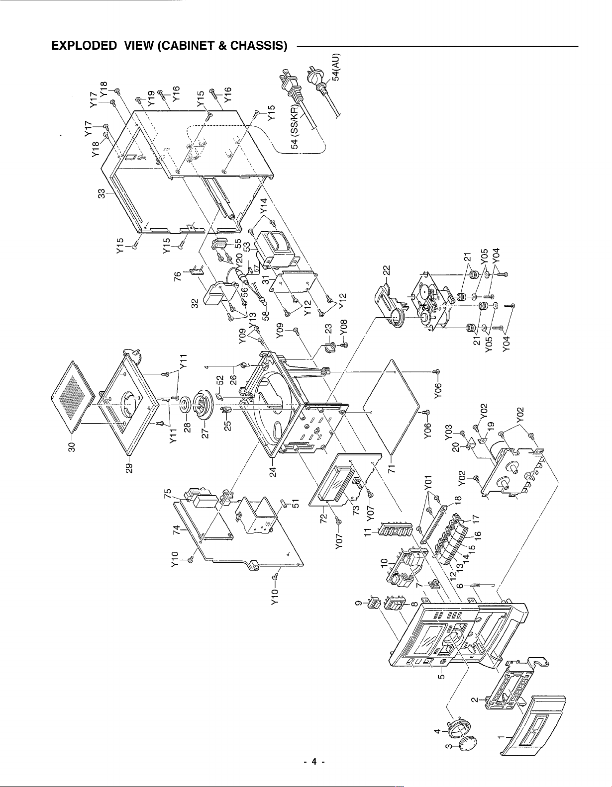
Exploded view
(Packing & Accessory, Cabinet & Chassis,
Fixing Parts, Electrical Parts & PWB Assy) ................. 4
(Tape mechanism) ........................................................9
(CD mechanism) ...........................................................9
Parts list
(Cabinet & Chassis) ......................................................5
(Tape mechanism) ........................................................9
(CD mechanism) ...........................................................9
PRODUCT CODE No.
129 587 02 (SS)
129 587 04 (AU)
129 587 06 (KR)
IC block diagram & description ........................................10
Schematic diagram
(CD)...............................................................................12
(FRONT) .......................................................................16
(AMPLIFIER)................................................................. 20
Wiring diagram
(CD, FRONT, LED for SS & KR)................................... 14
(CD, FRONT, LED for AU) ............................................ 18
(AMPLIFIER for SS & KR) ............................................22
(AMPLIFIER for AU)......................................................24
FL display description ......................................................26
Wiring connection ............................................................ 27
REFERENCE No.
SM5810137
Page 2
SPECIFICATIONS
Tuner
Reception frequency.............. FM : 87.5 - 108.0 MHz
MW :522-1710 kHz(9kHz step)
520 -1710 kHz(10kHz)
CD player
Channels................................ 2-channel stereo
Sampling frequency ............... 44.1 kHz
Pick-up................................... Optical 3-beam
semiconductor laser
Wow and Flutter..................... Below measurable limits
Cassette deck section
Track system ......................... 4-track, 2-channel stereo
Frequency response .............. 80 Hz - 13.5 kHz (Normal tape)
Signal to noise ratio ............... 45 dB
Wow and Flutter..................... 0.15% (WRMS)
Fast forward / Rewind time .... Approx. 110 sec. (C-60)
General
Output power ......................... 6 W x 2 (at 4 ohms, 10% distortion)
Inputs ..................................... VIDEO IN : 400 mV / 50k ohms
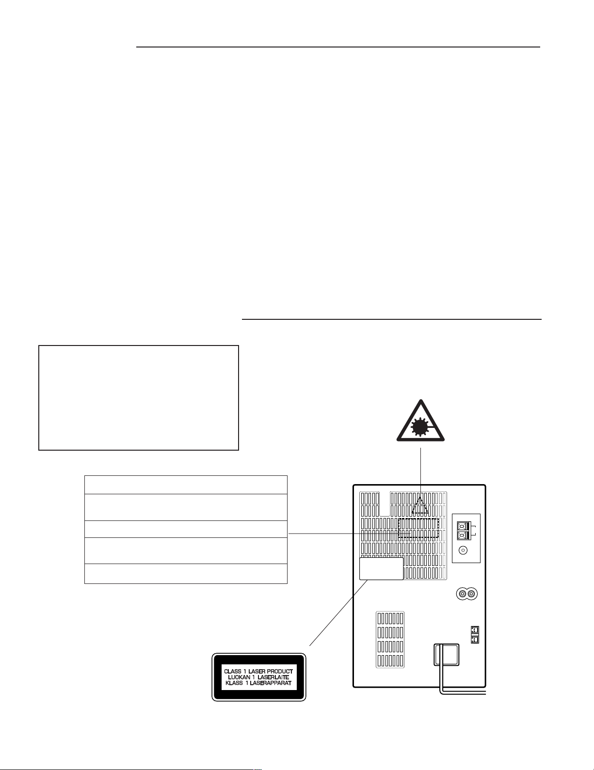
LASER BEAM SAFETY PRECAUTION
Outputs .................................. SPEAKERS : 4 ohms
PHONES : 8 - 32 ohms
Power requirements............... AC 110-120/220-240V
50/60 Hz (SS)
AC 230 -240V, 50 Hz (AU)
AC 220V, 60 Hz (KR)
Power consumption ............... 30 W
Dimensions (W x H x D) ........ Approx. 160 x 250 x 213 mm
Weight.................................... Approx. 2.8 kg
Speaker system
Type....................................... 2 Way bass reflex
Drivers ................................... 10 cm cone type (woofer)
5 cm cone type (tweeter)
Maximum
power-handling capacity ..... 12 Watts (peak)
Nominal impedance ............... 4 ohms
Dimensions (W x H x D) ........ Approx. 160 x 250 x 222 mm
Weight.................................... Approx. 1.9 kg (per speaker)
Specifications subject to change without notice.
• Pick-up that emits a laser beam is used in this CD player section.
CAUTION :
USE OF CONTROLS OR ADJUSTMENTS
OR PERFORMANCE OF PROCEDURES
OTHER THAN THOSE SPECIFIED HEREIN
MAY RESULT IN HAZARDOUS RADIATION
EXPOSURE
LASER OUTPUT..........0.6 mW Max. (CW)
WAVELENGTH ............. 790 nm
CAUTION – INVISIBLE LASER RADIATION WHEN OPEN AND
INTERLOCKS DEFEATED. AVOID EXPOSURE TO BEAM.
ADVARSEL – USYNLIG LASER STRÅLING VED ÅBNING, NÅR
SIKKERHEDSAFBRYDERE ER UDE AF FUNKTION, UNDGÅ UDS ÆTTELSE
FOR STRÅLING.
VARNING – OSYNLIG LASER STRÅLNING NÄR DENNA DEL ÄR ÖPPNAD
OCH SPÄRR ÄR URKOPPLAD. STRÅLEN ÄR FARLIG.
VORSICHT – UNSICHTBARE LASERSTRAHLUNG TRITT AUS, WENN
DECKEL GEÖFFNET UND WENN SICHERHEITSVERRIEGELUNG
ÜBERBRÜCKT IST. NICHT, DEM STRAHL AUSSETZEN.
VARO – AVATTAESSA JA SUOJALUKITUS OHITETTAESSA OLET ALTTIINA
NÄKYMÄTTÖMÄLLE LASERSÄTEILYLLE. ÄLÄ KATSO SÄTEESEEN.
EXT.ANT
AM
LOOP
FM
75Ω
IN
RRL
VIDEO
(AUDIO)
- 1 -
L
SPEAKERS
4Ω MIN
Page 3
CD PICK-UP MAINTENANCE
About pick-up (Optical lens) Cleaning
Clean a lens with swab of the cotton which moistened it with alcohol, cleaning paper or cleaning disc appointed.
Specified cleaning disc : LC-1 (Part code : 645 026 1961 ..... manufactured by SANYO.)
Show a clean procedure in the following in reference by swab of cotton.
1. Cotton swab is wrapped with Cleaning paper.
2. Add the isopropyl alcohol.
3. Gently move the tip of cotton swab just like a draw a whirlpool from inside to outside on the surface of lens.
CD PLAYER ADJUSTMENTS
1. ADJUSTMENTS
(1) Confirm the tracking balance
1. Connect an Oscilloscope to TP2 (TE) and TP4 (VC).
2. Turn on the POWER switch.
3. Set the test disc. (DISC 1)
4. Press "MEMORY" button and "BACK SKIP" button
simultaneously. Within 1 second after pressing the "PLAY/
PAUSE" button.
5. Confirm that the oscilloscope waveform is symmetrical on the
top and bottom in relation to 0V (VC).
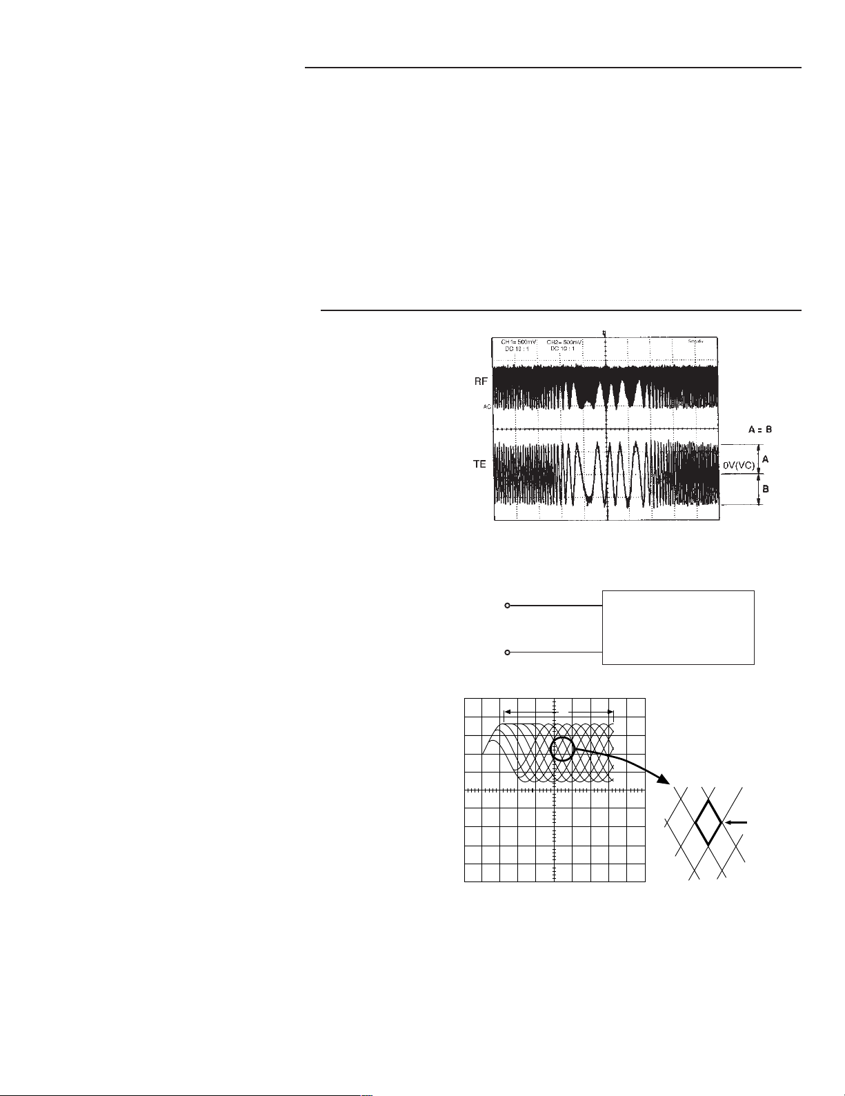
(2) Checking the "eye" pattern
1. Switch "ON" the POWER.
2. Connect an oscilloscope to TP1 (RF) and TP4 (VC).
3. Load the test disc.
4. Press the PLAY button.
5. Check to be sure that the "eye" pattern is at the center of
waveform and that the diamond shape is clearly defined.
6. Press the STOP button.
7. Turn off the POWER switch.
200mV/div.
5ms/div.
TP1
(RF)
TP4
(VC)
+
OSCILLOSCOPE
-
a
OPENING EXPANDED
b
- 2 -
Page 4
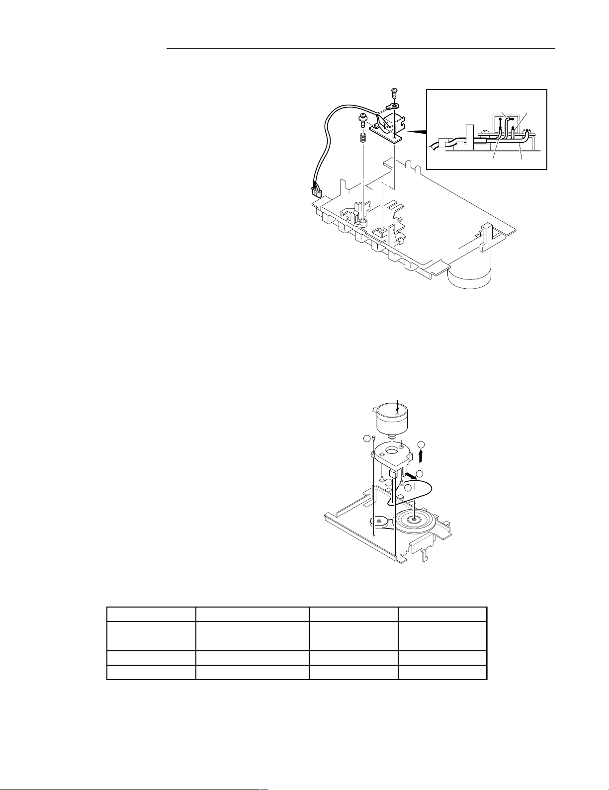
TAPE ADJUSTMENTS
a. Replacing the head
1. After replacement, demagnetize the heads by using a
degausser.
2. Be sure to clean the heads before attempting to make any
adjustments.
3. Be sure both channels (1 and 2) are the same level.
(Using a dual-channels oscilloscope).
4. All wiring should be returned to the original position after
work is completed.
b. Adjusting head azimuth
1. Load a test tape (VTT-738, etc. :10kHz) for azimuth
adjustment.
2. Press the PLAY button.
3. Use a cross-tip screwdriver to turn the screw for normal
azimuth adjustment so that the left and right outputs are
maximized at the same phase during normal playback.
4. Press the STOP button.
R / P HEAD
RED
WHITE
YELLOW EARTH
c. Adjusting motor speed
d. Replacing the motor
1. Insert the test tape (MTT-111 or etc. 3,000 Hz).
2. Press the PLAY button.
3. Use a flat-tip screwdriver to turn the SVR to adjust so that
the frequency counter becomes 3,000 Hz.
4. Press the STOP button.
e. Checking the mechanism torques
• Clean the head, capstan and pinch roller before making any measurement.
Measureent Take-up torque Back tension Tape tension
Cassette for PLAY : TW-2111A PLAY : TW-2111A Drive-power cassette
measurement F.FWD/REW : TW-2231 TW-2412
PLAY 30 ~ 70gr.cm 1.0 ~ 6.0gr.cm 80 gr or more
F.FWD/REW 55 gr or more - -
MOTOR SPEED
ADJUSTMENT
1
4
3
2
4
- 3 -
Page 5
Page 6

PARTS LIST
PRODUCT SAFETY NOTICE
EACH PRECAUTION IN THIS MANUAL SHOULD BE FOLLOWED DURING SERVICING. COMPONENTS IDENTIFIED WITH THE IEC
!!
SYMBOL
SPECIAL SIGNIFICANCE. WHEN REPLACING A COMPONENT IDENTIFIED BY
OR PARTS WITH THE SAME RATINGS OF RESISTANCE, WATTAGE OR VOLTAGE THAT ARE DESIGNATED IN THE PARTS LIST
IN THIS MANUAL. LEAKAGE-CURRENT OR RESISTANCE MEASUREMENTS MUST BE MADE TO DETERMINE THAT EXPOSED
PARTS ARE ACCEPTABLY INSULATED FROM THE SUPPLY CIRCUIT BEFORE RETURNING THE PRODUCT TO THE CUSTOMER.
CAUTION : Regular type resistors and capacitors are not listed. To know those values, refer to the schematic diagram.
!
IN THE PARTS LIST AND THE SCHEMATIC DIAGRAM DESIGNATED COMPONENTS IN WHICH SAFETY CAN BE OF
!!
!
, USE ONLY THE REPLACEMENT PARTS DESIGNATED,
Regular type resistors are less than 1/4 W carbon type and 0 ohm chip resistors.
Regular type capacitors are less than 50 V and less than 1000 µF type of Ceramic type and Electrical type.
PACKING & ACCESSORIES
REF.NO. PART NO. DESCRIPTION
614 311 3263 CARTON CASE (SS)
614 311 3287 CARTON CASE (AU)
614 312 4894 CARTON CASE (KR)
614 303 0652 CUSHION,FRONT
614 303 0669 CUSHION,REAR
614 311 3379 INSTRUCTION MANUAL (SS)
614 311 3393 INSTRUCTION MANUAL (AU)
614 312 5105 INSTRUCTION MANUAL (KR)
645 041 9027 POLY SHEET-0430X0290*NC,SET
645 037 9833 POLY BAG-0180X0250*NC,
1AV0L90B00200
645 036 6727 BATTERY COVER,SERVICE PART
614 310 0058 ASSY,BOX,SPEAKER, (L,R) (SS/AU)
614 312 4986 ASSY,BOX,SPEAKER, (L,R) (KR)
614 304 5311 ASSY,GRILLE
614 245 0055 ANTENNA,FM ANT
645 005 1227 ASSY,ANTENA,LOOP
645 017 2175 PLUG,ADAPTOR AC (SS)
or 645 006 4630 PLUG,ADAPTOR AC (SS)
645 034 7955 REMOCON,RB-DA100
614 309 3435 NOTICE (AU)
CABINET & CHASSIS
REF.NO. PART NO. DESCRIPTION
1 614 309 9734 ASSY,DOOR,DECK
2 614 302 5115 LID,CASSETTE
3 614 302 5092 KNOB,VR
4 614 306 4527 CAP,DECORATION
5 614 309 9758 ASSY,PANEL,FRONT
6 614 303 5794 SPRING,DOOR DECK
7 614 307 1396 ASSY,GEAR
8 614 302 9847 BUTTON,TUNER,2KEY
9 614 302 4859 BUTTON,POWER,1KEY
10 614 302 4927 BUTTON,PLAY,6KEY
11 614 302 4880 BUTTON,MEMORY,5KEY
12 614 309 9857 KNOB,DECK,MECHA,REC
13 614 309 9864 KNOB,DECK MECHA,PLAY
14 614 309 9871 KNOB,DECK MECHA,REW
15 614 309 9888 KNOB,DECK MECHA,FFWD
16 614 309 9895 KNOB,DECK MECHA,STOP/EJECT
17 614 309 9901 KNOB,DECK MECHA,PAUSE
18 614 309 9918 MOUNTING,DECK,KNOB
19 614 304 5700 HOLDER,MAIN PCB,MAIN PCB
20 614 303 0003 SPRING,DECK REC
21 614 298 8886 SPACER,MECHA,DAMPING KSM-213
22 614 302 4965 COVER,PICK-UP
24 614 302 5184 MOUNTING,PICK-UP
25 614 303 0263 LATCH,PUSH,CD DOOR LOCKING
26 614 303 0027 SPRING,DOOR CD
REF.NO. PART NO. DESCRIPTION
27 614 309 9239 PULLEY,CHECK PULLEY
28 614 303 0256 LATCH,MAGNET
29 614 309 9789 DOOR,CD
30 614 302 9878 DEC,DOOR CD
31 614 302 9915 HOLDER,POWER TRANS
32 614 307 8234 STOPPER,AC CORD
33 614 311 3058 ASSY,COVER,REAR (SS)
33 614 311 3072 ASSY,COVER,REAR (AU)
33 614 312 5006 ASSY,COVER,REAR (KR)
614 129 9136 LUG (KR)
FIXING PARTS
REF.NO. PART NO. DESCRIPTION
Y01 411 021 3503 SCR S-TPG BIN 3X10,
F-PANEL+DECK MECHA
Y02 411 021 3503 SCR S-TPG BIN 3X10,
F-PANEL+MTG DECK KNOB
Y03 411 126 1404 SCR S-TPG BIN 2X4,
SPRING DECK REC
Y04 411 021 1806 SCR S-TPG BIN 2.6X10,
MTG PK-UP+KSM-213
Y05 411 092 0906 WASHER Z 2.6X10X0.5,
MTG PK-UP+KSM-213
Y07 411 021 3503 SCR S-TPG BIN 3X10,
MTGPK-UP+FRONT PCB/CDPCB
Y08 411 021 3503 SCR S-TPG BIN 3X10,
MTG PK-UP+ASSS.GEAR
Y09 411 021 4500 SCR S-TPG BIN 3X16,
F-PANEL+MTG PK-UP
Y10 411 021 3503 SCR S-TPG BIN 3X10,MAIN PCB
Y11 411 021 2704 SCR S-TPG BIN 2.6X6,
DOOR CD+DEC DOOR CD
Y12 411 021 3503 SCR S-TPG BIN 3X10,
C-REAR+HOLDER P-TRANS
Y13 411 021 3503 SCR S-TPG BIN 3X10,
C-REAR+STOPPER CORD
Y14 411 020 9902 SCR S-TPG BRZ+FLG 3X8,
HOLDER P-TRANS+P-TRANS
Y15 411 098 7701 SCR S-TPG FLT 3X10,
C-REAR(L/R SIDE)
Y16 411 021 4500 SCR S-TPG BIN 3X16,C-REAR
Y17 411 021 3404 SCR S-TPG BIN 3X10,
C-REAR (ANT TERMINAL)
Y18 411 021 3404 SCR S-TPG BIN 3X10,C-REAR
Y19 411 021 3404 SCR S-TPG BIN 3X10,
C-REAR (RCA JACK)
Y20 411 021 3503 SCR S-TPG BIN 3X10,
VOLTAGE SELECT SW (SS)
- 5 -
Page 7

PARTS LIST
ELECTRICAL PARTS
REF.NO. PART NO. DESCRIPTION
614 305 9653 SHIELD
!!
51
!
423 016 7908 FUSE 250V 2.5A,LITTLE
52 645 013 5224 SWITCH,LEVER 1P-1T
!!
53
53
53
54
54
54
55
56
57
58
CN381
or
or
CN383
or
or
CN681
or
CN683
or
or
CN691
!
645 037 1813 TRANS,POWER (SS)
!!
!
645 037 1837 TRANS,POWER (AU)
!!
!
645 040 3149 TRANS,POWER (KR)
!!
!
645 037 7655 CORD,POWER (SS)
!!
!
645 037 7662 CORD,POWER (AU)
!!
!
645 039 9473 CORD,POWER (KR)
!!
!
645 037 1844 SWITCH,SLIDE 1P-1T (SS)
!!
!
423 016 9506 FUSE 250V 0.315A (KR)
!!
!
645 037 7501 ASSY, HOLDER, FUSE (KR)
!!
!
645 037 9888 TERMINAL CN555 (KR)
!!
!
614 311 0781 ASSY,WIRE
!!
!
614 304 1481 ASSY,WIRE
!!
!
614 308 2453 ASSY,WIRE
!!
!
614 311 0811 ASSY,WIRE
!!
!
614 304 1511 ASSY,WIRE
!!
!
614 308 2484 ASSY,WIRE
!!
!
645 036 3955 FLEXIBLE FLAT CABLE
!!
!
645 033 7413 FLEXIBLE FLAT CABLE
!!
!
614 304 1498 ASSY,WIRE
!!
!
614 308 2460 ASSY,WIRE
!!
!
614 311 0798 ASSY,WIRE
!!
!
645 041 2547 FLEXIBLE FLAT CABLE
FE001 645 013 6498 CORE,FERRITE (AU)
614 129 9136 LUG (AU)
CD P.W.BOARD ASSY
REF.NO. PART NO. DESCRIPTION
!!
71
71
71
C604 403 058 2901 POLYESTER 0.015U J 50V
C607 403 058 2901 POLYESTER 0.015U J 50V
C612 403 059 8209 POLYESTER 0.22U K 50V
C614 403 060 8700 POLYESTER 0.033U K 50V
C615 403 059 8209 POLYESTER 0.22U K 50V
C620 403 058 9504 POLYESTER 0.018U J 50V
C630 403 056 7502 POLYESTER 1000P J 50V
C631 403 060 8700 POLYESTER 0.033U K 50V
CN682
or
or
CP601 645 033 8168 SOCKET,FPC 16P
CP603 645 005 7366 PLUG,2P
or 614 310 2434 PLUG,2P (KR)
D601 407 012 4406 DIODE 1SS133
D602 407 012 0309 DIODE 1N4003
or 407 189 3301 DIODE 1N4004A
D603 407 012 0309 DIODE 1N4003
or 407 189 3301 DIODE 1N4004A
D604 407 099 5204 ZENER DIODE MTZJ5.1B
D605 407 099 5204 ZENER DIODE MTZJ5.1B
D841 407 012 0309 DIODE 1N4003
or 407 189 3301 DIODE 1N4004A
IC601 409 396 8100 IC LA9241ML
IC602 409 435 2106 IC LC78622NE
IC603 409 372 9602 IC LA6541
L600 645 037 2858 CORE,PIPE
L601 645 001 5519 INDUCTOR,47U K
L602 645 001 5519 INDUCTOR,47U K
L603 645 037 2858 CORE,PIPE
!
614 311 2297 ASSY,PWB,CD (SS) (Only Initial)
!!
!
614 311 2396 ASSY,PWB,CD (AU) (Only Initial)
!!
!
614 312 5365 ASSY,PWB,CD (KR) (Only Initial)
!!
!
614 304 1504 ASSY,WIRE
!!
!
614 311 0804 ASSY,WIRE
!!
!
614 308 2477 ASSY,WIRE
REF.NO. PART NO. DESCRIPTION
Q600 405 141 3505 TR KTA1266-Y
Q601 405 141 3505 TR KTA1266-Y
Q604 405 138 6403 TR KTD2058Y
Q605 405 000 3806 TR DTC114YS
or 405 143 0007 TR KRC107M
X600 614 231 2667 RESONATOR
FRONT P.W.BOARD ASSY
REF.NO. PART NO. DESCRIPTION
!!
72
72
72
AM001 614 304 5687 DEC,SHEET,LCD,LCD DIFFUSER
BRLCD 614 302 5085 HOLDER,LCD
CP101 645 012 5270 SOCKET,FPC 23P
D101 407 012 4406 DIODE 1SS133
D102 407 012 0804 DIODE 1N4148
D103
D104 407 099 6003 ZENER DIODE MTZJ9.1B
D114 407 012 0804 DIODE 1N4148
D115 407 012 4406 DIODE 1SS133
D116 407 012 0804 DIODE 1N4148
DMC10 407 203 9203 PHOTO DIODE SPS-442-1-E
IC101 410 345 9604 IC CXP83240A-110Q
IC102 409 451 2203 IC M24C02—MN6
J106 401 037 5004 MT-GLAZE 0.000 ZA 1/10W
J146 401 037 5004 MT-GLAZE 0.000 ZA 1/10W,
J147 401 037 5004 MT-GLAZE 0.000 ZA 1/10W,
J148 401 037 5004 MT-GLAZE 0.000 ZA 1/10W,
J203 401 037 5004 MT-GLAZE 0.000 ZA 1/10W
J204 401 037 5004 MT-GLAZE 0.000 ZA 1/10W,
J205 401 037 5004 MT-GLAZE 0.000 ZA 1/10W,
J206 401 037 5004 MT-GLAZE 0.000 ZA 1/10W,
J27 401 037 5004 MT-GLAZE 0.000 ZA 1/10W
L101 645 001 5441 INDUCTOR,2.2U K
LCD10 645 036 3931 LCD
Q101 405 000 3806 TR DTC114YS
or 405 143 0007 TR KRC107M
Q102 405 141 3307 TR KTC3198-GR
Q606 405 123 1208 TR DTC323TK
R101 401 038 6505 MT-GLAZE 47K JA 1/10W
R102 401 037 5608 MT-GLAZE 10K JA 1/10W
R103 401 037 5608 MT-GLAZE 10K JA 1/10W
R104 401 037 5608 MT-GLAZE 10K JA 1/10W
R105 401 037 5608 MT-GLAZE 10K JA 1/10W
R106 401 037 5608 MT-GLAZE 10K JA 1/10W
R107 401 037 5608 MT-GLAZE 10K JA 1/10W
R108 401 037 5608 MT-GLAZE 10K JA 1/10W
R109 401 038 0800 MT-GLAZE 22K JA 1/10W
R110 401 038 6406 MT-GLAZE 4.7K JA 1/10W
R111 401 038 7601 MT-GLAZE 560 JA 1/10W
R112 401 038 7601 MT-GLAZE 560 JA 1/10W
R113 401 038 7502 MT-GLAZE 56 JA 1/10W
R114 401 038 7502 MT-GLAZE 56 JA 1/10W
R115 401 038 7502 MT-GLAZE 56 JA 1/10W
R116 401 037 5202 MT-GLAZE 100 JA 1/10W
R117 401 038 6505 MT-GLAZE 47K JA 1/10W
R118 401 038 6505 MT-GLAZE 47K JA 1/10W
R119 401 037 5400 MT-GLAZE 1K JA 1/10W
!
614 311 2327 ASSY,PWB,FRONT (SS) (Only Initial)
!!
!
614 311 2426 ASSY,PWB,FRONT (AU) (Only Initial)
!!
!
614 312 5396 ASSY,PWB,FRONT (KR) (Only Initial)
!!
!
407 099 5303 ZENER DIODE MTZJ5.6B
CHIP JUMPER
CHIP JUMPER
CHIP JUMPER
CHIP JUMPER
CHIP JUMPER
CHIP JUMPER
- 6 -
Page 8

PARTS LIST
REF.NO. PART NO. DESCRIPTION
R120 401 037 5202 MT-GLAZE 100 JA 1/10W
R121 401 037 5608 MT-GLAZE 10K JA 1/10W
R122 401 037 5608 MT-GLAZE 10K JA 1/10W
R123 401 037 5400 MT-GLAZE 1K JA 1/10W
R124 401 037 7909 MT-GLAZE 1.5K JA 1/10W
R125 401 037 9200 MT-GLAZE 1.8K JA 1/10W
R126 401 038 2101 MT-GLAZE 2.7K JA 1/10W
R127 401 038 3603 MT-GLAZE 3.3K JA 1/10W
R128 401 038 7700 MT-GLAZE 5.6K JA 1/10W
R129 401 037 5608 MT-GLAZE 10K JA 1/10W
R130 401 037 9309 MT-GLAZE 18K JA 1/10W
R131 401 037 5400 MT-GLAZE 1K JA 1/10W
R132 401 037 7909 MT-GLAZE 1.5K JA 1/10W
R133 401 037 9200 MT-GLAZE 1.8K JA 1/10W
R134 401 038 2101 MT-GLAZE 2.7K JA 1/10W
R135 401 038 3603 MT-GLAZE 3.3K JA 1/10W
R136 401 038 7700 MT-GLAZE 5.6K JA 1/10W
R137 401 037 5608 MT-GLAZE 10K JA 1/10W
R138 401 037 5608 MT-GLAZE 10K JA 1/10W
R139 401 037 5608 MT-GLAZE 10K JA 1/10W
R140 401 038 6505 MT-GLAZE 47K JA 1/10W
R141 401 038 6505 MT-GLAZE 47K JA 1/10W
R145 401 037 5608 MT-GLAZE 10K JA 1/10W
R146 401 037 5608 MT-GLAZE 10K JA 1/10W
R147 401 037 5608 MT-GLAZE 10K JA 1/10W
R667 401 037 5202 MT-GLAZE 100 JA 1/10W
R668 401 037 5608 MT-GLAZE 10K JA 1/10W
SP101 401 037 5004 MT-GLAZE 0.000 ZA 1/10W
SW101 614 220 5471 SWITCH,TACT
SW102 614 220 5471 SWITCH,TACT
SW103 614 220 5471 SWITCH,TACT
SW104 614 220 5471 SWITCH,TACT
SW105 614 220 5471 SWITCH,TACT
SW106 614 220 5471 SWITCH,TACT
SW109 614 220 5471 SWITCH,TACT
SW110 614 220 5471 SWITCH,TACT
SW111 614 220 5471 SWITCH,TACT
SW112 614 220 5471 SWITCH,TACT
SW113 614 220 5471 SWITCH,TACT
SW114 614 220 5471 SWITCH,TACT
SW116 614 220 5471 SWITCH,TACT
SW117 614 220 5471 SWITCH,TACT
VOL10 645 033 3460 SWITCH,ROTARY(ENCODER)
X101 645 036 5102 OSC,CERAMIC 10.0MHZ
X102 645 032 1627 OSC,CRYSTAL 32.768KHZ
LED P.W.BOARD ASSY
REF.NO. PART NO. DESCRIPTION
!!
73
73
73
CN102 614 311 0774 ASSY,WIRE,FOR LED PCB
or 614 304 1474 ASSY,WIRE,FOR LED PCB
or 614 308 2446 ASSY,WIRE,FOR LED PCB
D105 408 037 4204 LED SLP-3118B-51HAB-T1
D106 408 037 4204 LED SLP-3118B-51HAB-T1
D107 408 037 4204 LED SLP-3118B-51HAB-T1
D108 408 037 4204 LED SLP-3118B-51HAB-T1
D109 408 037 4204 LED SLP-3118B-51HAB-T1
D110 408 037 4204 LED SLP-3118B-51HAB-T1
D111 408 037 4204 LED SLP-3118B-51HAB-T1
D112 408 037 4204 LED SLP-3118B-51HAB-T1
D113 408 037 4204 LED SLP-3118B-51HAB-T1
!
614 311 2303 ASSY,PWB,LED (SS) (Only Initial)
!!
!
614 311 2402 ASSY,PWB,LED (AU) (Only Initial)
!!
!
614 312 5372 ASSY,PWB,LED (KR) (Only Initial)
MAIN P.W.BOARD ASSY
REF.NO. PART NO. DESCRIPTION
!!
!
74
74
74
C201 403 058 2901 POLYESTER 0.015U J 50V
C209 403 058 2901 POLYESTER 0.015U J 50V
C216 403 060 8601 POLYESTER 0.033U K 50V
C404 403 057 5507 POLYESTER 1200P J 50V
C405 403 058 9504 POLYESTER 0.018U J 50V
C406 403 060 8700 POLYESTER 0.033U K 50V
C416 403 060 8700 POLYESTER 0.033U K 50V
C421 403 057 3503 POLYESTER 0.1U K 50V
C422 403 057 5507 POLYESTER 1200P J 50V
C427 403 059 5505 POLYESTER 0.022U J 50V
C428 403 062 4700 POLYESTER 5600P J 50V
C429 403 059 3204 POLYESTER 2200P J 50V
C434 403 060 8700 POLYESTER 0.033U K 50V
C507 403 277 4106 ELECT 1000U M 25V
C508 403 277 4106 ELECT 1000U M 25V
C509 403 057 2407 POLYESTER 0.1U J 50V
C510 403 057 2407 POLYESTER 0.1U J 50V
C516 403 334 5503 ELECT 3300U M 35V
CP201 645 012 5270 SOCKET,FPC 23P
CP202 645 004 2904 PLUG,4P
CP203 645 005 8110 PLUG,4P
CP204 645 007 1447 PLUG,2P,FOR PT LEAD
CP205 645 006 1875 PLUG,2P
CP206 645 006 1875 PLUG,2P
D201 407 099 5204 ZENER DIODE MTZJ5.1B
D202 407 127 5008 ZENER DIODE MTZJ2.2B
D401 407 012 0804 DIODE 1N4148
D501 407 099 5204 ZENER DIODE MTZJ5.1B
D502 407 012 0804 DIODE 1N4148
D504 407 099 5204 ZENER DIODE MTZJ5.1B
D505 407 012 0804 DIODE 1N4148
D508 407 189 3301 DIODE 1N4004A
or 407 012 0309 DIODE 1N4003
D509 407 189 3301 DIODE 1N4004A
or 407 012 0309 DIODE 1N4003
D510 407 012 0309 DIODE 1N4003
or 407 189 3301 DIODE 1N4004A
D511 407 189 3301 DIODE 1N4004A
or 407 012 0309 DIODE 1N4003
D512 407 012 0804 DIODE 1N4148
D513 407 099 6201 ZENER DIODE MTZJ10C
D514 407 012 0804 DIODE 1N4148
D515 407 012 0804 DIODE 1N4148
E002 645 031 7903 HOLDER,FUSE
or 645 006 4760 HOLDER,FUSE
E004 645 031 7903 HOLDER,FUSE
or 645 006 4760 HOLDER,FUSE
H/P1 645 011 6384 JACK,PHONE D3.6
HS401 614 302 9892 HEAT SINK
HTU01 614 304 5694 HOLDER,TU PCB
HTU02 614 304 5694 HOLDER,TU PCB
IC201 409 445 4503 IC M62439SP
IC401 409 451 7406 IC AN7348K
IC501 409 451 2104 IC TDA7269
JACK2 614 276 6835 SOCKET
L102 645 001 5441 INDUCTOR,2.2U K
L103 645 001 5441 INDUCTOR,2.2U K
L401 645 006 1523 INDUCTOR,470U J
L402 645 006 1523 INDUCTOR,470U J
L403 645 006 1523 INDUCTOR,470U J
L404 645 037 2858 CORE,PIPE
L405 645 037 2858 CORE,PIPE
614 311 2280 ASSY,PWB,MAIN (SS) (Only Initial)
!!
!
614 311 2389 ASSY,PWB,MAIN (AU) (Only Initial)
!!
!
614 312 5358 ASSY,PWB,MAIN (KR) (Only Initial)
- 7 -
Page 9

REF.NO. PART NO. DESCRIPTION
L406 645 037 2858 CORE,PIPE
L407 645 037 2858 CORE,PIPE
Q201 405 154 5909 TR KRC231M
Q202 405 154 5909 TR KRC231M
Q203 405 143 0007 TR KRC107M
or 405 000 3806 TR DTC114YS
Q204 405 151 5209 TR KRA107M
or 405 000 0904 TR DTA114YS
Q401 405 141 3307 TR KTC3198-GR
Q402 405 141 3307 TR KTC3198-GR
Q403 405 155 0002 TR MPSA56
Q404 405 143 0007 TR KRC107M
or 405 000 3806 TR DTC114YS
Q501 405 143 0007 TR KRC107M
or 405 000 3806 TR DTC114YS
Q502 405 143 0007 TR KRC107M
or 405 000 3806 TR DTC114YS
Q503 405 151 5209 TR KRA107M
or 405 000 0904 TR DTA114YS
Q504 405 158 9309 TR KTC3202-Y
Q505 405 154 9907 TR KTK117Y
Q506 405 151 5209 TR KRA107M
or 405 000 0904 TR DTA114YS
Q507 405 138 6502 TR KTB1366Y
Q508 405 141 3307 TR KTC3198-GR
Q509 405 141 3307 TR KTC3198-GR
Q510 405 143 0007 TR KRC107M
or 405 000 3806 TR DTC114YS
R201 401 038 0701 MT-GLAZE 2.2K JA 1/10W
R202 401 038 0800 MT-GLAZE 22K JA 1/10W
R203 401 038 0800 MT-GLAZE 22K JA 1/10W
R204 401 038 0800 MT-GLAZE 22K JA 1/10W
R205 401 038 7700 MT-GLAZE 5.6K JA 1/10W
R206 401 037 5608 MT-GLAZE 10K JA 1/10W
R207 401 037 5608 MT-GLAZE 10K JA 1/10W
R208 401 038 7700 MT-GLAZE 5.6K JA 1/10W
R209 401 038 2200 MT-GLAZE 27K JA 1/10W
R210 401 038 9209 MT-GLAZE 6.8K JA 1/10W
R211 401 038 2200 MT-GLAZE 27K JA 1/10W
R212 401 038 9209 MT-GLAZE 6.8K JA 1/10W
R213 401 038 0800 MT-GLAZE 22K JA 1/10W
R215 401 038 0800 MT-GLAZE 22K JA 1/10W
R216 401 037 6704 MT-GLAZE 1.2K JA 1/10W
R217 401 038 0701 MT-GLAZE 2.2K JA 1/10W
R218 401 038 3603 MT-GLAZE 3.3K JA 1/10W
R219 401 038 9209 MT-GLAZE 6.8K JA 1/10W
R220 401 038 3603 MT-GLAZE 3.3K JA 1/10W
R221 401 038 9209 MT-GLAZE 6.8K JA 1/10W
R222 401 038 0800 MT-GLAZE 22K JA 1/10W
R226 401 038 6307 MT-GLAZE 470 JA 1/10W
R227 401 038 0800 MT-GLAZE 22K JA 1/10W
R228 401 038 0800 MT-GLAZE 22K JA 1/10W
R229 401 038 0800 MT-GLAZE 22K JA 1/10W
R230 401 038 0800 MT-GLAZE 22K JA 1/10W
R231 401 038 0800 MT-GLAZE 22K JA 1/10W
R232 401 038 0800 MT-GLAZE 22K JA 1/10W
R233 401 038 6505 MT-GLAZE 47K JA 1/10W
R234 401 037 5608 MT-GLAZE 10K JA 1/10W
R235 401 037 6704 MT-GLAZE 1.2K JA 1/10W
R236 401 037 5608 MT-GLAZE 10K JA 1/10W
R401 401 094 1902 MT-GLAZE 10M JA 1/10W
R402 401 037 5608 MT-GLAZE 10K JA 1/10W
R403 401 037 6902 MT-GLAZE 120K JA 1/10W
R404 401 038 6307 MT-GLAZE 470 JA 1/10W
R405 401 038 3405 MT-GLAZE 33 JA 1/10W
R406 401 038 0800 MT-GLAZE 22K JA 1/10W
R407 401 038 0800 MT-GLAZE 22K JA 1/10W
R408 401 038 3405 MT-GLAZE 33 JA 1/10W
REF.NO. PART NO. DESCRIPTION
R409 401 038 6307 MT-GLAZE 470 JA 1/10W
R410 401 037 6902 MT-GLAZE 120K JA 1/10W
R411 401 038 0800 MT-GLAZE 22K JA 1/10W
R412 401 038 0800 MT-GLAZE 22K JA 1/10W
R413 401 037 5608 MT-GLAZE 10K JA 1/10W
R414 401 038 0800 MT-GLAZE 22K JA 1/10W
R415 401 038 0800 MT-GLAZE 22K JA 1/10W
R416 401 037 5400 MT-GLAZE 1K JA 1/10W
R417 401 038 0800 MT-GLAZE 22K JA 1/10W
R418 401 038 5300 MT-GLAZE 39K JA 1/10W
R419 401 038 9308 MT-GLAZE 68K JA 1/10W
R420 401 038 5300 MT-GLAZE 39K JA 1/10W
R421 401 038 7809 MT-GLAZE 56K JA 1/10W
R423 401 037 8005 MT-GLAZE 15K JA 1/10W
R424 401 037 5608 MT-GLAZE 10K JA 1/10W
R425 401 037 5608 MT-GLAZE 10K JA 1/10W
R426 401 037 5608 MT-GLAZE 10K JA 1/10W
R427 401 038 6505 MT-GLAZE 47K JA 1/10W
R428 401 038 7601 MT-GLAZE 560 JA 1/10W
R501 401 038 5300 MT-GLAZE 39K JA 1/10W
R502 401 037 5608 MT-GLAZE 10K JA 1/10W
R503 401 037 5400 MT-GLAZE 1K JA 1/10W
R504 401 037 8005 MT-GLAZE 15K JA 1/10W
R505 401 037 5608 MT-GLAZE 10K JA 1/10W
R506 401 037 8005 MT-GLAZE 15K JA 1/10W
R507 401 038 0602 MT-GLAZE 220 JA 1/10W
R509 401 037 8005 MT-GLAZE 15K JA 1/10W
R510 401 038 7601 MT-GLAZE 560 JA 1/10W
R511 401 038 7601 MT-GLAZE 560 JA 1/10W
R512 401 037 5806 MT-GLAZE 1M JA 1/10W
R513 401 038 6505 MT-GLAZE 47K JA 1/10W
R514 401 037 5400 MT-GLAZE 1K JA 1/10W
R518 401 037 8005 MT-GLAZE 15K JA 1/10W
R519 401 038 6406 MT-GLAZE 4.7K JA 1/10W
R520 401 037 5202 MT-GLAZE 100 JA 1/10W
R521 401 038 0602 MT-GLAZE 220 JA 1/10W
R522 401 038 6406 MT-GLAZE 4.7K JA 1/10W
R523 401 037 5400 MT-GLAZE 1K JA 1/10W
R528 401 037 5608 MT-GLAZE 10K JA 1/10W
R529 401 038 6307 MT-GLAZE 470 JA 1/10W
R530 401 037 6605 MT-GLAZE 120 JA 1/10W
S401 645 036 3924 SWITCH,LEAF,R/P SW
SA001 411 021 6405 SCR S-TPG BIN 3X8,HEAT SINK IC401
SA002 411 021 6405 SCR S-TPG BIN 3X8,HEAT SINK Q507
SA003 411 021 6405 SCR S-TPG BIN 3X8,TUNER ASSY
SA004 411 021 6405 SCR S-TPG BIN 3X8,YUNER ASSY
SHANT 614 305 3637 SHIELD,ANTENA
TU001 645 037 1776 TUNER,MW/FM (SS/AU)
TU001 645 037 1783 TUNER,MW/FM (KR)
AC TERMINAL P.W.BOARD ASSY
REF.NO. PART NO. DESCRIPTION
76
76
76
T901 614 017 8203 TERMINAL BOARD
T902 614 017 8203 TERMINAL BOARD
!!
!
614 311 2310 ASSY,PWB,ACCORD(SS) (Only Initial)
!!
!
614 311 2419 ASSY,PWB,ACCORD(AU) (Only Initial)
!!
!
614 312 5389 ASSY,PWB,ACCORD(KR) (Only Initial)
- 8 -
Page 10

EXPLODED VIEW (TAPE MECHANISM)
TM03
TM05
TM04
TM06
TM01
TM02
TAPE MECHANISM (TM-DA70TN-SH ... Only Initial)
REF.NO. PART NO. DESCRIPTION
614 309 7976 ASSY,MECHA,TM-DA70TN-SH
TM01 645 041 3025 R.P HEAD AP-4211F
TM02 645 009 1612 PINCH ROLLER ARM ASSY
TM03 645 033 8625 E HEAD 6PA
TM04 645 009 1766 RF BELT
TM05 645 033 3415 MAIN BELT
TM06 614 304 1467 ASSY,MOTOR
EXPLODED VIEW (CD MECHANISM)
PM05
PM03
PM04
PM01-1
PM02
PM08
PM06
PM09
CD MECHANISM(CD213CDM/SNSH... Only initial)
REF.NO. PART NO. DESCRIPTION
PM01 614 304 5571 ASSY,MOTOR CHASSIS,
BASE CHASSIS
PM01-1 645 033 6812 GEAR B RP,SLED GEAR
PM02 645 033 6744 ASSY,MOTOR GEAR,
SLED MOTOR ASSY
PM03 645 033 6805 SLED SHAFT,PICK RAIL
PM01
PM04 645 033 6799 GEAR A S,PICK DRIVE GEAR
PM05 645 033 6829 SCREW+P2*3,SLED MOTOR FIX
PM06 645 033 6775 LEAF SWITCH,LIMIT SWITCH
PM07 645 033 6782 MOTOR 6P S PCB,PCB
PM08 645 033 6768 CONNECTOR PIN 6P,CONNECTOR
PM09 614 303 5626 PICK UP
PM07
- 9 -
Page 11

Page 12

IC BLOCK DIAGRAM & DESCRIPTION
IC602 LC78622E (Digital Signal Processor)
No. Pin Name I/O Function
1 DEFI I Input terminal for detect signal of defect
2 TAI I Input terminal for test.
3 PDO O The phase comparison output terminal for
external VCO control.
4 VVSS - Ground terminal for built-in VCO
5 ISET I Resistance connection terminal for
electric current adjustment of PDO output.
6 VVDD - Built-in VCO power supply terminal.
7 FR I VCO frequency range adjustment.
8 VSS - Ground for Digital
9 EFMO O EFM signal output terminal for slice level control.
10 EFMIN I EFM signal input terminal for slice level control.
11 TEST2 I TEST pin. Normal time is non connection.
12 CLV+ O Output terminal for Disc motor control.
13 CLV- O Output terminal for Disc motor control.
14 V/P O Change of rough servo / phase control
Rough servo : "H", Phase control : "L"
15 HFL I Input terminal of track search signal.
16 T ES I Input terminal of tracking error signal.
17 TOFF O Output terminal of tracking off.
18 T GL O Output terminal for change of tracking gain.
19 JP+ O Output terminal for tracking jump control.
20 JP- O Output terminal for tracking jump control.
21 PCK O Clock monitor output terminal for EFM data
playback. (4.3218 MHz)
22 FSEQ O Output terminal for detect of SYNC signal.
23 DVDD - +5V
24 CONT1 I/O
25 CONT2 I/O This output can control at serial control from
26 CONT3 I/O micro processor.
27 CONT4 I/O
28 CONT5 I/O
29 EMPH O Output terminal of de-emphasis monitor .
"H" : de-emphasis
30 C2F O Output terminal of C2 flag
31 DOUT O Output terminal of digital out
No. Pin Name I/O Function
32 TEST3 I Test pin.
33 TEST4 I Test pin.
34 NC - Non connection.
35 MUTEL O Mute output terminal for L-ch
36 LVDD - Power supply for L-ch
37 LCHO O Output terminal for L-ch
38 LVSS - GND for L-ch
39 RVSS - GND for R-ch
40 RCHO O Output terminal for R-ch
41 RVDD - Power supply for R-ch
42 MUTER O Mute output terminal for R-ch
43 XVDD - Power supply of crystal oscillation
44 XOUT O Connection terminal of crystal oscillation (16.9344MHz)
45 XIN I Connection terminal of crystal oscillation (16.9344MHz)
46 X VS S - GND of crystal oscillation
47 S BSY O Output terminal for synchronizing signal of
sub-cord block
48 EFLG O Output terminal for correction monitor of C1, C2,
Single and Double
49 PW O Output terminal for sub-cord of P, Q, R, S, T, U and W
50 SFSY O Output terminal for synchronizing signal of
sub-cord frame
51 SBCK I Input terminal for readout clock of sub-cord
52 FS X O Output terminal of Synchronizing signal (7.35kHz)
53 WRQ O Output terminal for standby of sub-cord Q output
54 RWC I Input terminal of read / write control
55 SQOUT O Out put t ermi nal o f sub-cord Q
56 COIN I Input terminal of command from micro processor
57 CQCK I Clock input for reading sub-cord from SQOUT
58 RES I Reset (turn on : L)
59 TST11 O Test pin
60 16M O 16.9344MHz
61 4.2M O 4.2336MHz
62 TEST5 I Test pin
63 CS I Chip select terminal
64 TEST1 I Test pin
DEFI
EFMIN
FSEQ
CLV+
CLV-
SBCK
SBSY
SFSY
WRQ
SQOUT
CQCK
COIN
RWC
EFMO VVDD VVSS PDO ISET FR
9
1
Slice level
Control
10
Syncrnous Detect
22
EFM Demodulation
12
13
14
V/P
PW
49
51
47
50
63
CS
53
55
57
56
54
CLV
Digital Servo
Subcode Dxract
QCRC
COM
Inter Fase
Servo Commander
15 16 17 20 19 58 18 24 25 26 27 28 29 48 60 61 46 52 45 44 43 39 41 42 40 37 35 38 36
4
6
TGL
RESJP+JP-TOFFTESHFL
357 2
VCO Clock Oscillator
& Clock Control
General Ports
CONT3
CONT1
CONT4
CONT2
PCK
TAI
21
TST11
TEST1 TEST3 TEST5
59 64 11 32 33 62
2K~8bit
RAM
C1 C2 Error Detect &
Correct Control Flag
X’tal Root
Timing Generator
4.2M16MEFLGEMPHCONT5
XVSS
VDDVSS
23
8
RAM Address
Interpolalation Mute
Digital Attenuator
Quadruple Over Sampling
Digital Filter
RVDD
XVDD
XINFSX
RVSS
XOUT
MUTER
TEST2 TEST4
- 11 -
Generatorl
Billingual
1bit DAC
L.P.F
RCHO
Digital Out
MUTELLCHO
LVSS
LVDD
C2F
30
31
DOUT
(NC)
34
Page 13

SCHEMATIC DIAGRAM (CD)
This is a basic schematic diagram.
PRODUCT SAFETY NOTICE
Each precaution in this manual should be followed during servicing. Components identified with the IEC symbol
designated components in which safety can be of special significance. When replacing a component identified by
designated, or parts with the same ratings of resistance, wattage or voltage that are designated in the parts list in this manual. Leakage-current or resistance
measurements must be made to determine that exposed parts are acceptably insulated from the supply circuit before returning the product to the customer.
in the parts list and the schematic diagram
!!
!
!!
!
, use only the replacement parts
- 13 -- 12 -
Page 14

WIRING DIAGRAM (CD, FRONT, LED for SS & KR)
<TOP VIEW>
FRONT P.W.B
CD P.W.B
- 14 -
Page 15

WIRING DIAGRAM (CD, FRONT, LED for SS & KR)
<BOTTOM VIEW>
FRONT P.W.B
LED P.W.B
TOP
CD P.W.B
- 15 -
Page 16

SCHEMATIC DIAGRAM (FRONT)
This is a basic schematic diagram.
- 17 -- 16 -
Page 17

WIRING DIAGRAM (CD, FRONT, LED for AU)
<TOP VIEW>
FRONT P.W.B
CD P.W.B
- 18 -
Page 18

WIRING DIAGRAM (CD, FRONT, LED for AU)
<BOTTOM VIEW>
FRONT P.W.B
LED P.W.B
TOP
CD P.W.B
- 19 -
Page 19

SCHEMATIC DIAGRAM (AMPLIFIER)
This is a basic schematic diagram.
PRODUCT SAFETY
NOTICE
Each precaution in this
manual should be
followed during servicing.
Components identified
with the IEC symbol
the parts list and the
schematic diagram
designated components
in which safety can be of
special significance.
When replacing a
component identified by
!!
!
, use only the
replacement parts
designated, or parts with
the same ratings of
resistance, wattage or
voltage that are
designated in the parts
list in this manual.
Leakage-current or
resistance
measurements must be
made to determine that
exposed parts are
acceptably insulated from
the supply circuit before
returning the product to
the customer.
in
!!
!
- 21 -- 20 -
Page 20

WIRING DIAGRAM (AMPLIFIER for SS & KR)
<TOP VIEW>
- 22 -
Page 21

WIRING DIAGRAM (AMPLIFIER for SS & KR)
<BOTTOM VIEW>
- 23 -
Page 22

WIRING DIAGRAM (AMPLIFIER for AU)
<TOP VIEW>
- 24 -
Page 23

WIRING DIAGRAM (AMPLIFIER for AU)
<BOTTOM VIEW>
- 25 -
Page 24

FL DISPLAY DESCRIPTION
S1
T1
T2
1
2
S2
S3
3
45 67
S4
S6
S5
COM1 COM2 COM3 COM4
1 COM1 - - 2 - COM2 - 3 - - COM3 4 - - - COM4
5 1F 1G 1E OFF
8
COL
P
S7
T3
V1
V2
V3
V4 V5 V6
*1
V7
COM1 COM2 COM3 COM4
23 5K 5J 5N 5D
24 5B 5H 5C COL
25 6F 6G 6E P
26 6A 6I 6M 6L
27 6K 6J 6N 6D
A
FI K
J
G
H
M
E
L
N
D
B
C
6 1A 1I 1M 1L
7 1K 1J 1N 1D
8 1B 1H 1C REC
9 2F 2G 2E SLEEP
10 2A 2I 2M 2L
11 2K 2J 2N 2D
12 2B 2H 2C S2
13 3F 3G 3E S3
14 3A 3I 3M 3L
15 3K 3J 3N 3D
16 3B 3H 3C S4
17 4F 4G 4E S5
18 4A 4I 4M 4L
19 4K 4J 4N 4D
20 4B 4H 4C S6
21 5F 5G 5E S7
22 5A 5I 5M 5L
28 6B 6H 6C RANDOM
29 7F 7G 7E SURR.
30 7A 7I 7M 7L
31 7K 7J 7N 7D
32 7B 7H 7C REPEAT
33 8F 8G 8E MHz
34 8A 8I 8M 8L
35 8K 8J 8N 8D
36 8B 8H 8C KHz
37 T1 T2 ON S1
38 ST MONO RDS T3
39 21019
40 412311
41 614513
42 816715
43 *1 V1 V2 V3
44 V4 V5 V6 V7
- 26 -
Page 25

 Loading...