

SANYO DCA010 Datasheet
SANYO Electric Co.,Ltd. Semiconductor Company
TOKYO OFFICE Tokyo Bldg., 1-10, 1 Chome, Ueno, Taito-ku, TOKYO, 110-8534 JAPAN
Ordering number : EN1892B
DCA010
Silicon Epitaxial Planar Type (Anode Common)
DCA010
Very High-Speed Switching Diode
Features
•
Ideally suited for use in hybrid ICs because
of very small-sized package.
• Fast switching speed.
• Small interterminal capacitance.
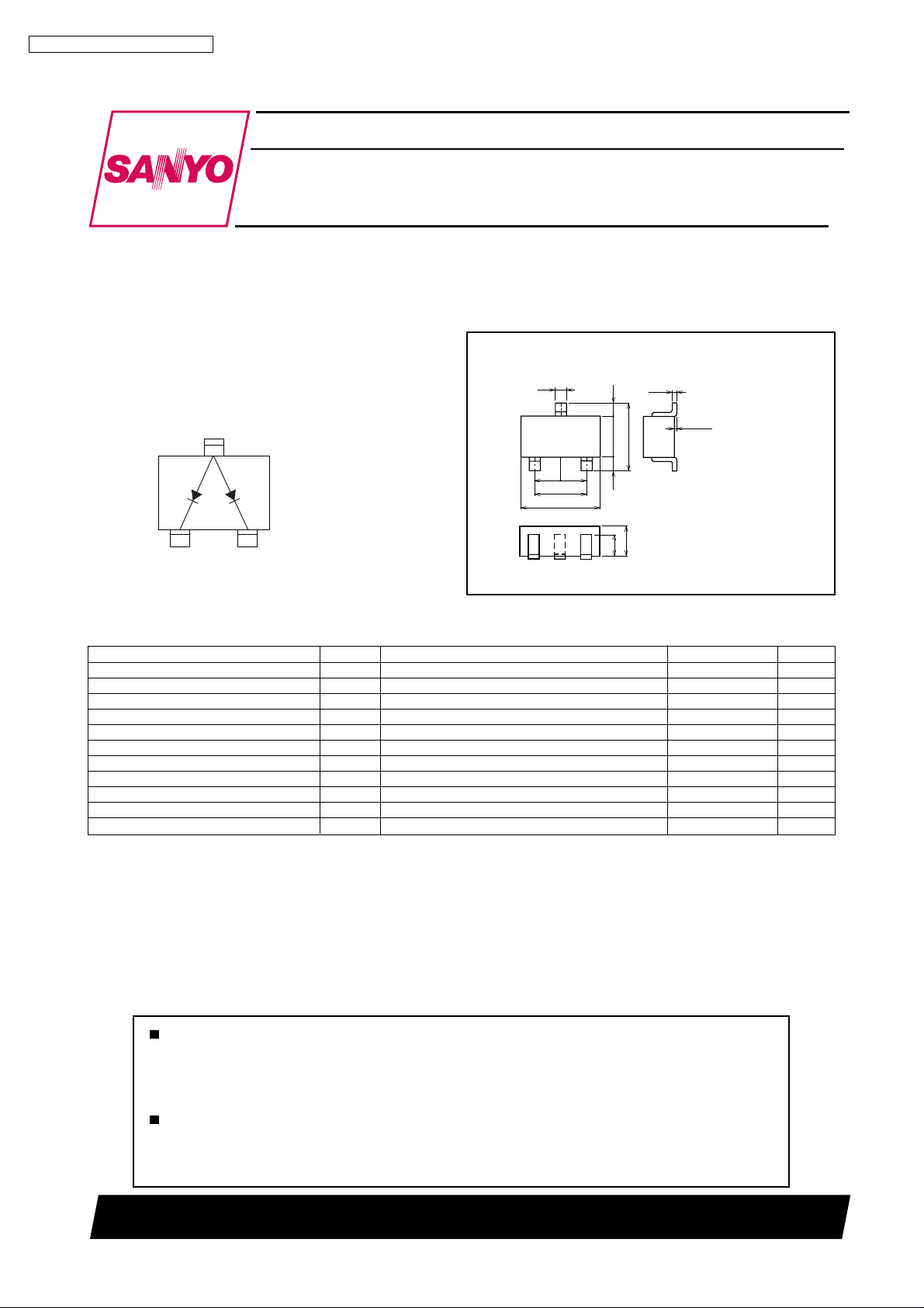
Electrical Connection
Anode
3
Package Dimensions
unit : mm
1117B
[DCA010]
0.4
3
0.95
0.95
1
1.9
2.9
0.5
2.5
1.5
2
0.5
0.16
0 to 0.1
1 : Cathode
2 : Cathode
3 : Anode
21
Cathode
(Top view)
Cathode
1.1
0.8
SANYO : CP
Specifications
Absolute Maximum Ratings at T a=25°C
Parameter Symbol Conditions Ratings Unit
Peak Reverse Voltage V
Reverse Voltage V
Peak Forward Current I
Average Rectified Current I
Surge Current (1µs) I
Allowable Power Dissipation P 200 mW
Junction T emperature Tj 125 °C
Storage T emperature T stg --55 to +125 °C
RM
R
FM
O
FSM
Unit rating 300 mA
Total rating 450 mA
Unit rating 100 mA
Total rating 150 mA
Unit rating 4 A
Total rating 6 A
85 V
80 V
Any and all SANYO products described or contained herein do not have specifications that can handle
applications that require extremely high levels of reliability, such as life-support systems, aircraft's
control systems, or other applications whose failure can be reasonably expected to result in serious
physical and/or material damage. Consult with your SANYO representative nearest you before using
any SANYO products described or contained herein in such applications.
SANYO assumes no responsibility for equipment failures that result from using products at values that
exceed, even momentarily, rated values (such as maximum ratings, operating condition ranges, or other
parameters) listed in products specifications of any and all SANYO products described or contained
herein.
12000 GI IM / 2019MO, TS
No.1892-1/3
DCA010
Electrical Characteristics at Ta=25°C
Parameter Symbol Conditions min typ max Unit
Forward Voltage V
Reverse Current I
F1
V
F2
V
F3
R1
I
R2
IF=1mA 0.61 V
IF=10mA 0.74 V
IF=100mA 1.20 V
VR=30V 0.1 µA
VR=80V 0.5 µA
Interterminal Capacitance C VR=0, f=1MHz 4.0 pF
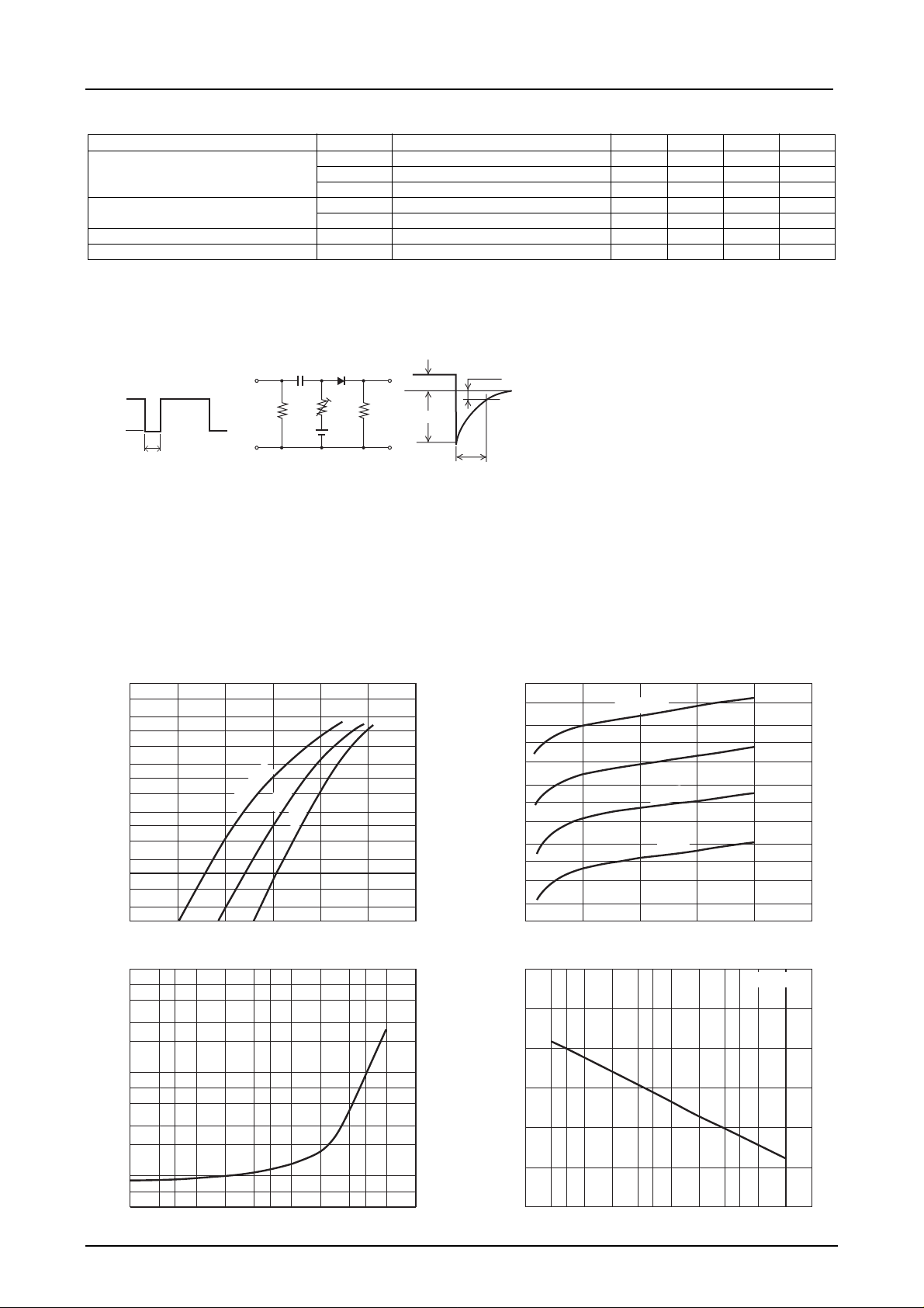
Reverse Recovery Time t
rr
IF=10mA, VR=6V, RL=50Ω, Irr=0.1Irp 4.0 ns
Marking : W5
Reverse Recovery Time Test Circuit
0.01µF
--6V
DUT
0
50Ω
2kΩ
50Ω
IF=10mA
Irp
0.1Irp
50ns
IF -- V
3
10
5
2
2
10
5
2
-- mA
F
10
5
2
1.0
5
2
Forward Current, I
--1
10
5
2
--2
10
0 0.2 0.4 0.6 0.8 1.0 1.2
Ta=100°C
F
25°C
--25°C
Forward Voltage, VF -- V
trr -- I
100
-- ns
rr
Reverse Recovery Time, t
1.0
7
5
3
2
10
7
5
3
2
7
5
0.1
352
1.0
Forward Current, IF -- mA
F
352
10 100
t
rr
IR -- V
75°C
50°C
25°C
C -- V
R
R
23 5 2
10 100
10
5
2
1.0
5
-- µA
R
2
--1
10
5
2
--2
10
Reverse Current, I
5
2
--3
10
0 20406080100
IT02033 IT02034
3.0
2.5
2.0
1.5
1.0
0.5
Interterminal Capacitance, C -- pF
352
IT02035 IT02036
0
0.1
23 5
Ta=100°C
Reverse Voltage, VR -- V
23 5
1.0
Reverse Voltage, VR -- V
f=1MHz
No.1892-2/3
 Loading...