

Page 1
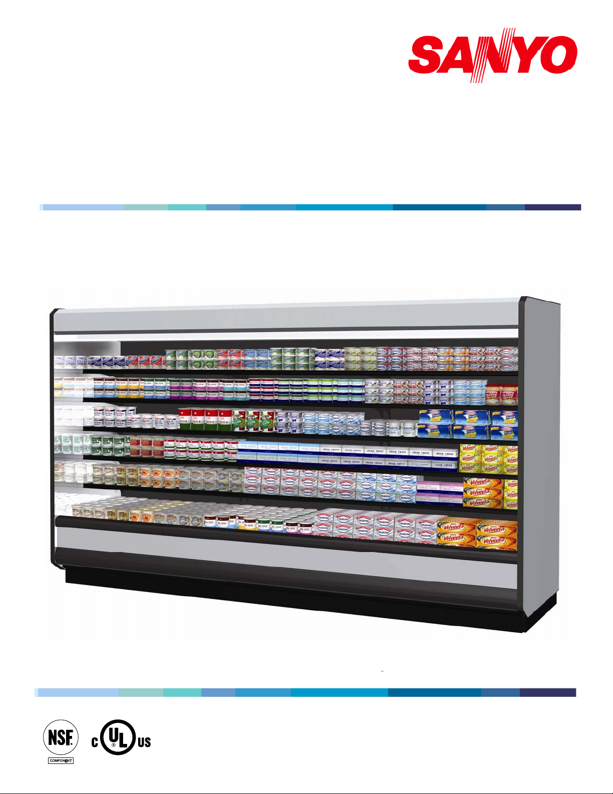
MULTI-DECK DAIRY and DELI CASES
CPW-EXA185 / CPW-EXA125
(H: 80 7/8”, L: 96 3/8”) / (H: 80 7/8”, L: 144 5/8”)
INSTALLATION & SERVICE MANUAL
REMOTE TYPE DISPLAY CASE
CPW-EXA285 / CPW-EXA225
(H: 84 7/8”, L: 96 3/8”) / (H: 84 7/8”, L: 144 5/8”)
2010
Page 2
Activity Safety Precautions
In order to prevent any injuries to person, equipment and/or damage to the SANYO Cases, sections requiring
additional care to be undertaken will have one or all of the following safety reminders:
Red Safety Mark (Safety M ark A)
Extreme caution and care must be exercised when conducting this operation to ensure personal
A
and equipment safety, and to prevent product damage.
Failure to exercise extreme caution may result i n severe personal injury and/or equipment and/or
product damage.
Yellow Safety Mark (Safety M ark B)
Caution and care should be exercised when conducting this operation to ensure personal and
equipment safety, and to prevent product damage.
B
Failure to exercise caution may result in personal injury and/or equipment and/or product
damage.
Hand Protection Required
Activities to be undertaken require finger and palm protection equipment to prevent personal
injuries.
General Safety Precautions
Safety Equipment Required
Any installation where there is overhead work being conducted simultaneously where a SANYO
Case is being unloaded and/or set/aligned, proper safety equipment including headgear is
required to ensure personal safety.
2
Page 3

TABLE OF CONTENTS
1 SPECIFICATIONS .................................................................................................................................................. 5
1.1 CPW-EXA285 / CPW-EXA225 ......................................................................................................................... 5
1.2 CPW-EXA185/ CPW-EXA125 .......................................................................................................................... 6
2 DIMENSIONS........................................................................................................................................................... 7
2.1 EXTERNAL DIMENSIONS ..................................................................................................................................... 7
2.2 FOOTPRINT .......................................................................................................................................................... 7
2.3 EXTERNAL DIMENSIONS ..................................................................................................................................... 8
2.4 FOOTPRINT .......................................................................................................................................................... 8
3 UNLOADING AND CARPENTRY PROCEDURES ........................................................................................... 9
3.1 NSF CERTIFICATION ........................................................................................................................................... 9
3.2 LOCATION ........................................................................................................................................................... 9
3.3 SHIPPING DAMAGE.............................................................................................................................................. 9
3.4 UNLOADING INSTRUCTIONS & PRECAUTIONS .................................................................................................... 9
3.5 ALIGNING CASES .............................................................................................................................................. 10
3.6 CASE LEVELING ................................................................................................................................................ 10
3.7 JOINING INSTRUCTIONS .................................................................................................................................... 11
3.7.1 Applying gasket (for connecting cases or installing side panels). ............................................................ 11
3.7.2 Connecting cases. ..................................................................................................................................... 12
3.8 INSTALLING PATCH ENDS ................................................................................................................................. 13
3.9 INSTALLING KICKPLATE ................................................................................................................................... 14
3.10 INSTALLING HANDRAIL AND BUMPER .............................................................................................................. 15
4 REFRIGERATION, PLUMBING & ELECTRICAL PROCEDURES ............................................................ 16
4.1 PIPING (PLUMBING, REFRIGERATION) .............................................................................................................. 16
4.2 ELECTRICAL DATA ............................................................................................................................................ 17
4.3 ELECTRICAL – GUIDELINES & PRECAUTIONS ................................................................................................... 17
4.4 WIRING ............................................................................................................................................................. 17
4.4.1 Wiring Color Code ................................................................................................................................... 17
4.4.2 Wiring Diagram ........................................................................................................................................ 18
5 OPERATION .......................................................................................................................................................... 19
5.1 SHELF LOAD LIMITS ......................................................................................................................................... 19
REFRIGERATION LOAD LIMITS ......................................................................................................................... 21
5.2
5.3
INSTALLING FDA/NSF THERMOMETER ........................................................................................................... 21
3
Page 4

6 CARE AND CLEANING GUIDELINES ............................................................................................................. 22
6.1 EXTERIOR PANELS (DAILY CLEANING) ............................................................................................................ 22
6.2 ACRYLIC SHELF GUARD & PRICE TAG MOLDING (DAILY CLEANING) ............................................................ 22
6.3 SHELF SURFACES (DAILY CLEANING) .............................................................................................................. 23
6.4 SHELF ASSEMBLIES (WEEKLY CLEANING) ....................................................................................................... 23
6.5 MIRRORS, FLUORESCENT LAMPS, DRAIN TRAP (MONTHLY CLEANING) ......................................................... 24
6.6 HONEYCOMB ASSEMBLIES (AT LEAST EVERY 3 MONTHS) ............................................................................... 24
7 SERVICE ................................................................................................................................................................ 25
7.1 REPLACING FAN MOTORS AND BLADES ........................................................................................................... 25
7.2 REPLACING ELECTRONIC BALLASTS ................................................................................................................ 28
7.3 REPLACING FLUORESCENT LAMPS ................................................................................................................... 29
7.4 EXPANSION VALVE ........................................................................................................................................... 30
4
Page 5
1 Specifications
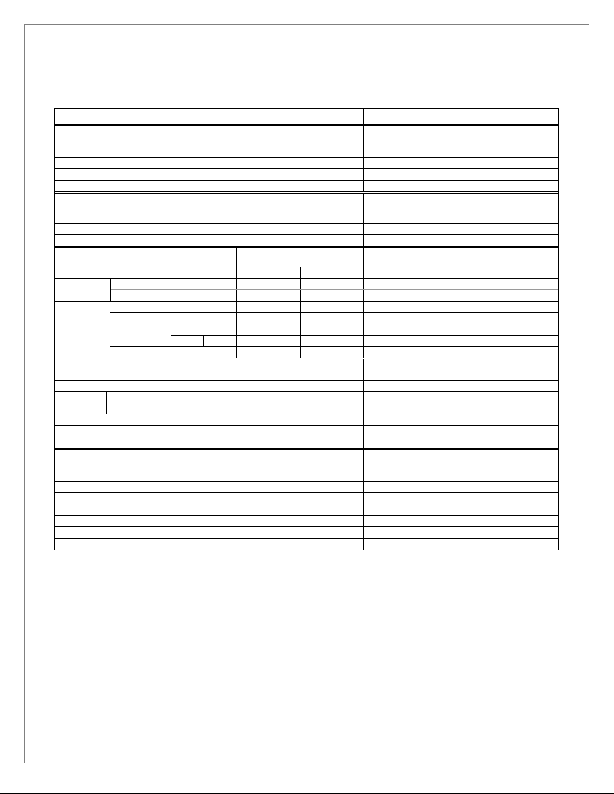
1.1 CPW-EXA285 (H: 84 7/8”, L: 96 3/8”) / CPW-EXA225 (H: 84 7/8”, L: 144 5/8”)
Model Name CPW-EXA285
General
Application: Medium Temperature (Dairy / Deli) Medium Temperature (Dairy / Deli)
Cooling Capacity:
Discharge Air: 30.0°F (-1.11°C) 30.0°F (-1.11°C)
Evaporator Temperature: 22.0°F (-5.56°C) 22.0°F (-5.56°C)
Defrost (Off-cycle)
Frequency (times per day): 4, once every 6 hours 4 , once every 6 hours
Termination Temperature: 50.0°F 50.0°F
Failsafe/Duration: 30 minutes 30 minutes
Electrical
Anti-condensation Heater:
Fan
Motor:
Lights:
Standard:
High Efficiency:
Exterior: 2 Rows of Lamps
Interior:
Total: Standard
Components
Anti-condensation Heater: N/A N/A
Fan
Motor:
Fan Blade Pitch:
Illumination: FO32/XP (T8) (Output 32W) FO32/XP (T8) (Output 32W)
Pipe Diameter: Liquid 3/8”, Suction 3/4” Liquid 3/8”, Suction 3/4”
Standard:
High Efficiency:
1,280 BTU/h/ft.(3700W) 1,2800 BTU/h/ft.(4500W)
Medium Temperature Medium Temperature
1-phase 120V
Top Panel
Handrail
Shelves 4-Shelf
Inside#128×2, Outside#128 x 1 Inside#128 x 3, Outside#117 x 2
N/A N/A
195W 2.28A
84W 1.29A
110W 0.94A
N/A N/A
55W 0.47A
N/A N/A
165W 1.41A
SPFBE141 x 3 SPFBE141 x 3 , SPFBE91T x 2
SSC2B12CNHBV1 x 3 SSC2B12CNHBV1 x 3 , SSC2B12BVHBV1 x 2
2 Rows of Lamps
Top Panel
Handrail
Shelves 4-Shelf
Standard
CPW-EXA225
1-phase 120V
N/A N/A
285W 3.42A
126W 1.93A
166W 1.42A
N/A N/A
83W 0.71A
N/A N/A
248W 2.13A
Measurements
Outer Dimensions: 84 7/8” (H) × 42 1/2” (W) × 96 3/8” (L) 84 7/8” (H) × 42 1/2” (W) × 144 5/8” (L)
Open Space: 61 1/2” 61 1/2”
Display Area: 86.8 sq.ft. 130.4 sq.ft
Effective Capacity: 73.8 cu.ft. 110.7 cu.ft.
Shelf Dimensions:
Weight: 716.5 lbs 1036.0 lbs
Waste Outlet Dimensions: 1 1/2” 1 1/2”
Standard Ambient Conditions: Indoor temperature 75°F (24°C), relative humidity 55%, wind speed under 39.4 fpm.
All specifications are based upon temperature, humidity, and wind speed values equal to or less than Standard Ambient Conditions.
SANYO Cases described in this manual are designed for indoor use only. SANYO Cases should not be exposed to direct sunlight.
Fan Motors are available in Standard-type (AC Fan Motors) or High Efficiency-type (DC Fan Motors).
Display Area Effective Capacity data specifications based on 4 (four) 20” shelves set at 0° (flat). Any variations from this specification
will affect overall data.
4-Shelf
8 Shelves (20” depth) 12 Shelves (20” depth)
5
Page 6
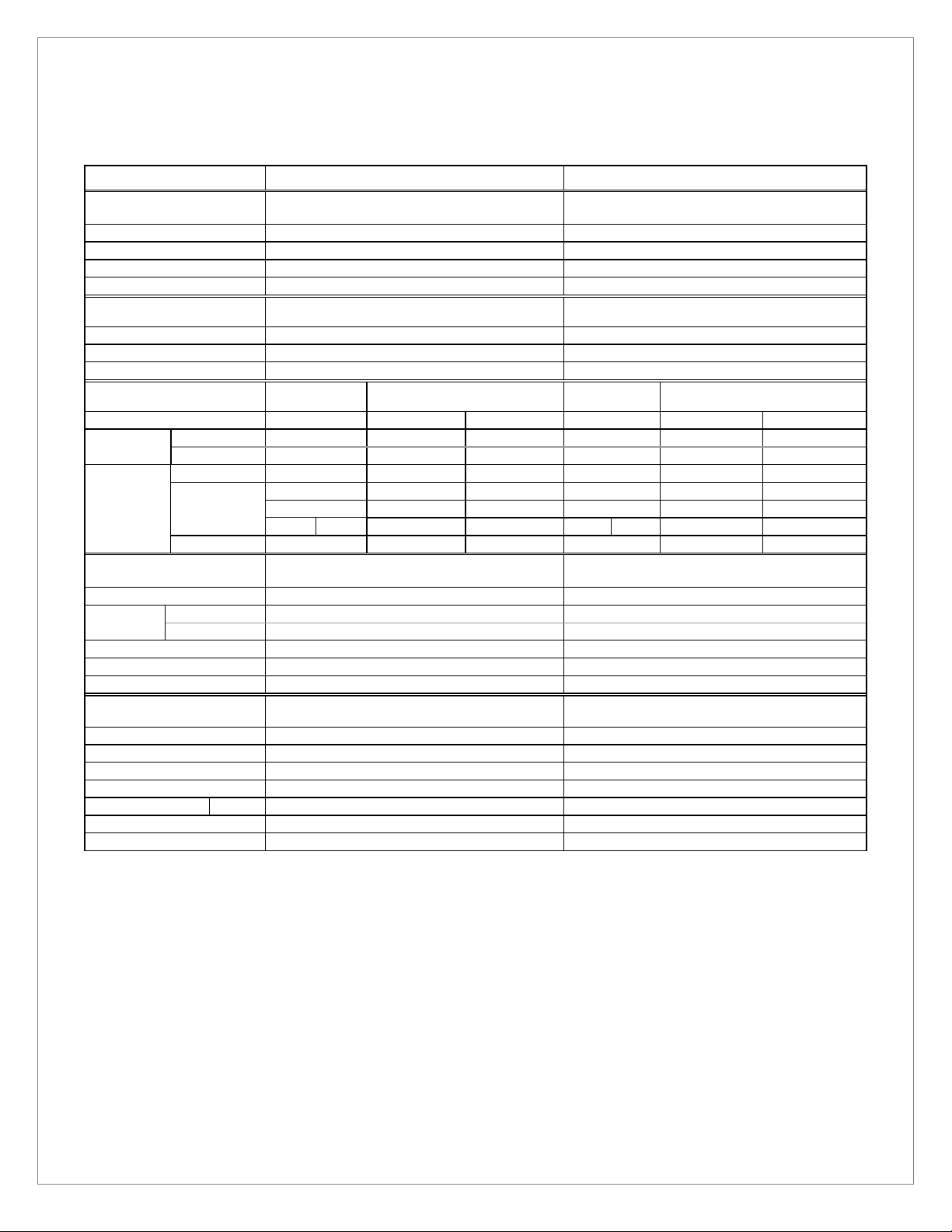
1.2 CPW-EXA185 (H: 80 7/8”, L: 96 3/8”) / CPW-EXA125 (H: 80 7/8”, L: 144 5/8”)
Model Name CPW-EXA185
General
Application: Medium Temperature (Dairy / Deli) Medium Temperature (Dairy / Deli)
Cooling Capacity:
Discharge Air: 30.0°F (-1.11°C) 30.0°F (-1.11°C)
Evaporator Temperature: 22.0°F (-5.56°C) 22.0°F (-5.56°C)
Defrost (Off-cycle)
Frequency (times per day): 4, once every 6 hours 4, once every 6 hours
Termination Temperature: 50.0°F 50.0°F
Failsafe/Duration: 30 minutes 30 minutes
Electrical
Anti-condensation Heater:
Fan
Motor:
Lights:
Standard:
High Efficiency:
Exterior: 2 Rows of Lamps
Interior:
Total: Standard
Components
Anti-condensation Heater: N/A N/A
Fan
Motor:
Fan Blade Pitch:
Illumination: FO32/XP (T8) (Output 32W) FO32/XP (T8) (Output 32W)
Pipe Diameter: Liquid 3/8”, Suction 3/4” Liquid 3/8”, Suction 3/4”
Standard:
High Efficiency:
1,249 BTU/h/ft.(2925W) 1,249 BTU/h/ft.(4390W)
Medium Temperature Medium Temperature
1-phase 120V
Top Panel
Handrail
Shelves 4-Shelf
Inside#128×2, Outside#128 x 1 Inside#128 x 3, Outside#117 x 2
N/A N/A
195W 2.28A
84W 1.29A
110W 0.94A
N/A N/A
55W 0.47A
N/A N/A
165W 1.41A
SPFBE141 x 3 SPFBE141 x 3 , SPFBE91T x 2
SSC2B12CNHBV1 x 3 SSC2B12CNHBV1 x 3 , SSC2B12BVHBV1 x 2
2 Rows of Lamps
Top Panel
Handrail
Shelves 4-Shelf
Standard
CPW-EXA125
1-phase 120V
N/A N/A
285W 3.42A
126W 1.93A
166W 1.42A
N/A N/A
83W 0.71A
N/A N/A
248W 2.13A
Measurements
Outer Dimensions: 80 7/8” (H) × 42 1/2” (W) × 96 3/8 ” (L) 80 7/8” (H) × 42 ½” (W) × 144 5/8” (L)
Open Space: 60.0” 60.0”
Display Area: 73.4 sq.ft. 110.1 sq.ft
Effective Capacity: 72.0 cu.ft. 108.0 cu.ft.
Shelf Dimensions:
Weight: 705.0 lbs 1019.0 lbs
Waste Outlet Dimensions: 1 1/2” 1 1/2”
Standard Ambient Conditions: Indoor temperature 75°F (24°C), relative humidity 55%, wind speed under 39.4 fpm.
All specifications are based upon temperature, humidity, and wind speed values equal to or less than Standard Ambient Conditions.
SANYO Cases described in this manual are designed for indoor use only. SANYO cases should not be exposed to direct sunlight.
Fan Motors are available in Standard-type (AC Fan Motors) or High Efficiency-type (DC Fan Motors).
Display Area Effective Capacity data specifications based on 4 (four) 20” shelves set at 0° (flat). Any variations from this specification
will affect overall data.
4-Shelf
8 Shelves (20” depth) 12 Shelves (20” depth)
6
Page 7
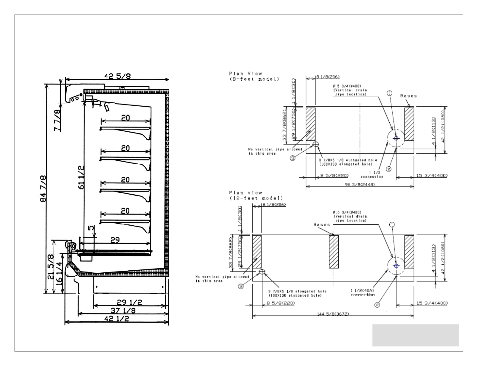
CPW-EXA285 / FPW-EXA225
2 Dimensions
2.1 External Dimensions
2.2 Footprint
① Waste Outlet
* Dimensions given in inches and millimeters (mm in parentheses).
② Electrical Connection
③ Refrigeration Outlet
Page 8
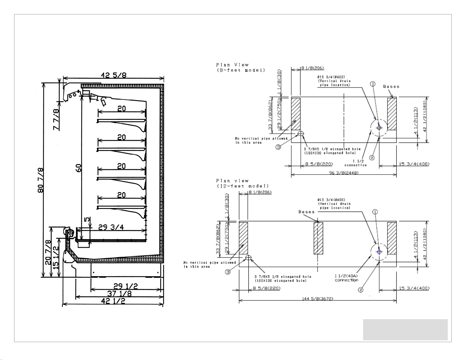
2.3 External Dimensions
2.4 Footprint
* Dimensions given in inches and millimeters (mm in parentheses).
① Waste Outlet
② Electrical Connection
Refrigeration Outlet
③
Page 9
3 Unloading and Carpentry Procedures
3.1 NSF Certification
The SANYO Cases described in this manual are built to meet the requirements of American National Standard/NSF
International Standard 7. Each SANYO Case bears a nameplate identifying the type of application for which it was certified:
Type I display refrigerator/freezer: Intended for use in an area where the environmental conditions are controlled and
maintained so that the ambient temperature typically does not exceed 75°F.
3.2 Location
As noted above, the SANYO Cases described in this manual are design for the display of products in interior spaces with
climate control, with ambient conditions typically maintained below 75°F and 55% relative humidity. Proper SANYO Case
performance cannot be guaranteed when ambient temperature and/or humidity exceed this level.
SANYO Cases should not be exposed to direct sunlight or other sources of heat.
SANYO Cases should not be exposed to strong air currents, as these may disrupt the dual air curtains used to maintain
proper temperature inside the merchandiser display area.
3.3 Shipping Damage
All SANYO Cases and peripheral equipment should be examined for shipping damage prior to and during offloading. All
SANYO Cases and peripheral equipment are given a through outgoing inspection upon leaving our warehouse, and the
carrier assumes responsibility for the safe arrival of our cases.
APPARENT DAMAGE: Any obvious loss or damage should be noted immediately at the time of receipt on the freight bill or
express receipt and signed by the carrier’s agent. Failure to do so may lead to rejection of the claim by the carrier.
CONCEALED DAMAGE: If damage that is not apparent during unloading is found after unpacking, retain all packing materials
and submit a written request to the carrier for inspection within 15 days.
LOST ITEMS: Any claims related to lost or missing items must be made to SANYO North America Corporation, Commercial
Solutions Division within 48 hours of receipt of equipment.
3.4 Unloading Instructions & Precautions
WARNING!
SANYO Cases are heavy and bulky, and require at least two people for unloading, moving, and installation.
Do not remove the wooden beam from the bottom front edge of each SANYO Case until the cases have been moved into
place in the store lineup.
Do not walk on the top of the SANYO Cases. Walking on the top of the SANYO Case may lead to serious injury and/or
damage to the case.
Do not place anything on the top of the SANYO Case or use the top of any SANYO Case for short- or long-term storage.
Recommended Practices for Unloading SANYO Cases:
1. Use a J-Bar (Johnson Bar) to lift one end of the merchandiser.
2. Insert one or more dollies under the base leg.
3. Lift the other side with the J-Bar.
4. (Optional) Insert one or more dollies.
5. Move the SANYO Case out of the container.
6. Use dollies on both ends of the SANYO Case to move to lineup location after unloading from container.
9
Page 10
3.5 Aligning Cases
WARNING!
SANYO Cases are heavy and bulky, and require at least two people for unloading, moving, and installation.
Do not walk on the top of the SANYO Cases. Walking on the top of the SANYO Case may lead to serious injury and/or
damage to the case.
Do not place anything on the top of the SANYO Case or use the top of any SANYO Case for short- or long-term storage.
1. Review layout drawings for spaces where SANYO Cases are to be installed.
2. Based on the layout drawings and the SANYO Case footprint drawings, mark the floor to indicate the exact locations of
the base legs (back edge and front edge) on each case. Multiple SANYO Cases should be aligned based upon the position
of the base legs.
3. Snap chalk lines for the front and rear positions of the legs on each row of SANYO Case.
4. Mark the location showing the outside edge of each base leg on each SANYO Case.
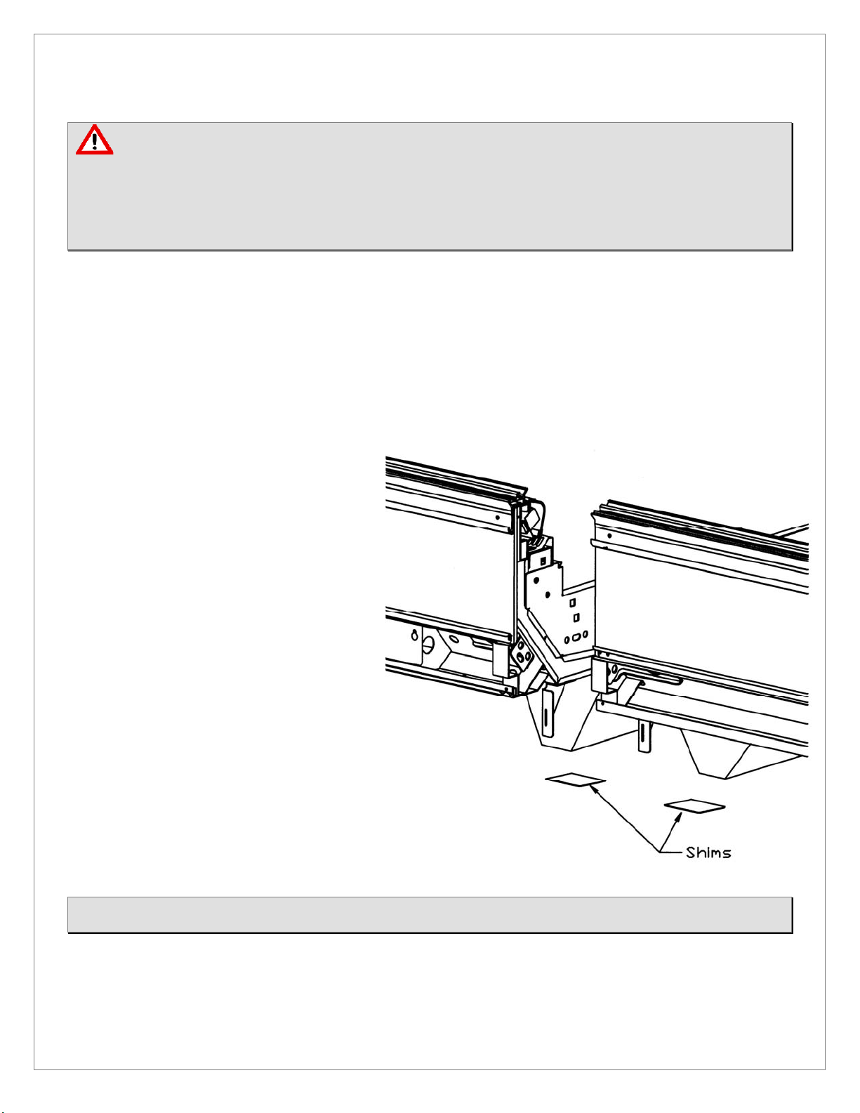
3.6 Case Leveling
SANYO Cases must be installed level in order to ensure proper performance and drainage.
1. For each lineup of SANYO Cases to be joined,
use a level (preferably a laser level) to find
the highest point on the front and rear chalk
lines marked in step 3 above (during Case
Alignment).
2. Determine which of the two points marked
on the line is higher. This is the highest
point in the case lineup.
3. Estimate the number of shims needed for
the four corners of each case position, in
order to bring all positions to the same
height as the highest point found in step 2.
4. For each row, place the first SANYO Case
where it will sit over the highest point in the
lineup. Ensure that the case is level, using
shims as needed.
5. Continue placing cases in the lineup,
working outward to both sides from the
position of the first case placed. Use shims
to ensure that all cases in the lineup are
level
NOTE: Each base leg must rest on solid supports. Insert shims as needed if there are any gaps between the floor and each
base leg.
10
Page 11

3.7 Joining Instructions
3.7.1 Applying Gasket (for connecting cases or installing side panels).
① Make sure that all SANYO Cases are resting level (verify using level).
② Make sure that all required parts for joining are present (gasket, bolts, joint covers, nuts, etc.).
③ Remove all Shelves, Rear Interior Panels, Wire Racks, Deck Pans, and Front Air Grilles from the far right and left
ends of each case being joined.
④ Thoroughly clean all surfaces where the gasket will be placed to remove anything that might affect adhesion.
⑤ Place gasket along the areas shown in bold in the drawing at bottom. When connecting two cases, apply gasket to
one case only.
CAUTION!
Perimeter gasket is required by NSF.
Do not stretch or twist gasket when applying.
Do not leave gaps. Always overlap gasket rather than leaving gaps.
Gasket ends that are open must be sealed off by applying silicone at the installation site.
Insufficient or improper sealing may lead to insufficient cooling and condensation.
11
Page 12

3.7.2 Connecting Cases.
① Apply gasket as described above.
② Connect cases by using the attached bolts and nuts.
CPW-EXA285/225
Silicone Seal
NOTE: Connection point must be sili cone sealed.
NOTE: Gasket ends that are open must be sealed off by applying silicone at the installation site.
CPW-EXA185/125
Connection Difference
12
Page 13

3.8 Installing Patch Ends
CPW-EXA285/225
① Gasket
② M8 Bolts
③ Side Cover
④ Suction Lamp Cover Joint
⑤ M5 Bolts
CPW-EXA185/125
1. Apply gasket to case body (per previous instructions).
2. If present, remove protective film from inside wall of
patch end.
3. Place patch end to line up with bolt holes.
4. From inside unit ratchet in M8 & optional M5 bolt into
patch end until secure.
5. Apply Silicone sealant between inside of patch end and
lower frame (see drawing to the left for details).
6. Attach side cover (item 3 in above drawing).
13
Apply silicone sealant inside after installing the
patch end.
Silicon seal
Page 14

3.9 Installing Kickplate
1. Align the mounting hole in the Kickplate with the slot in the Kickplate Mounting Bracket on the SANYO Case
and tighten accordingly.
14
Page 15

3.10 Installing Handrail and Bumper
Handrail
Handrail
Attaching the Bumper
1. Attach Maintenance Bumper (length 39-3/8 inches) to bumper brackets over the electrical
connection box (“raceway”) on each SANYO Case. The Raceway is located on the right end of each
SANYO Case.
2. Attach Full-Length Bumpers between Maintenance Bumpers on separate SANYO Cases, and also
between Maintenance Bumpers and Patch Ends.
3. Cut Full-Length Bumpers to size on-site. Cut to correct size so that no gaps remain between pieces.
Attaching the Handrail
1. Starting at one end of SANYO Case line-up, attach pieces of Handrail to Handrail Retainer, butting
the pieces end-to-end without gaps.
2. When you reach the final piece of Handrail to be installed between the last SANYO Case in the
line-up and the patch end, cut that piece to length so there are no gaps between Handrails or
between Handrails and Patch Ends.
3. Cut Handrail to size on-site. Cut to correct size so that no gaps remain between pieces.
WARNING!
Wear appropriate eye and hand protection and exercise care when using powered tools to prevent personal injuries and
damage to the case.
15
Page 16

4 R efrigeration, Plumbing & Electrical Procedures
4.1 Piping (Plumbing, Refrigeration)
● U-trap installation
Install U-Trap referring to the drawing below.
● Sealing the refrigerant pipe opening
Seal pipe completely.
Insufficient sealing may cause the following problems:
Insufficient cooling
Excessive frost
Icing over
Condensation on the bottom of case.
Part Name Part Number
①
Drain Screen 8FL2162000500
②
O-ring 8FL2646000100
③
Drain Trap 8FL2658000200
16
Page 17

4.2 Electrical Data
Please refer to Specifications section and nameplate attached to the SANYO Case for electrical information.
4.3 Electrical – Guidelines & Precautions
All wiring and electrical field work must comply with the National Electrical Code (“NEC”) and other applicable local codes.
All electrical connections must be made inside the raceway area.
4.4 Wiring
4.4.1 Wiring Color Code
WARNING!
While undertaking any electrical work, ensure that the case is not plugged-in and/or the power has been turned off at the
source and that the source has been flagged appropriately to indicate that work is being conducted to prevent personal
injuries and damage to the case.
17
Page 18

4.4.2 Wiring Diagram
18
Page 19

5 Operation
5.1 Shelf Load Limits
Although SANYO Cases are shipped from the factory with the Shelf Brackets and Shelves set at 5 degrees, in order to
maintain Maximum Distributed Load Capacity of 330lbs (150kgs) per shelf, it is required that the shelves be re-set at 0
“zero” degrees upon installation and prior to merchandising.
5 (five) Degree Setting 0 “zero” Degree Setting
Ensure that all Shelf Brackets are installed on the same horizontal plane, do not have one Shelf Bracket Higher, or
lower, than the other, as this will cause exaggerated stress to develop.
Exaggerated stress will contribute to Shelf Bracket and/or Shelf failure, especially during merchandise
replenishment when the load capacity is no longer equally distributed along the shelf.
If the Shelf Bracket and Shelves are to be set at less than 0 “zero” please keep in mind that while the Maximum
Distributed Load Capacity of 330lbs (150kgs) per shelf will be maintained, however, the susceptibility to
exaggerated stress will increase.
The PTM (Price Tag Molding) was not designed nor engineered to be a product stop, therefore, use of the PTM as a
product stop on any and all shelves set less than 0 “zero” is not recommended as it cannot support merchandise
and prevent it from falling.
It is strongly recommended that periodic checks of the Shelf Brackets and Shelves be conducted to ensure that
neither have been affected by any instances of having exceeded the Maximum Distributed Load Capacity of 330lbs
(150kgs) per shelf.
Replace any and all Shelf Brackets and Shelves immediately to maintain the performance integrity of the SANYO
Case.
Shelf Placement:
19
Page 20

5.2 Refrigeration Load Limits
In order to maintain proper temperature and unit performance, the dual air curtains in each SANYO Case must remain
unobstructed:
Do not stock shelves beyond the marked load limits.
Do not block Honeycombs or Return Air Grilles.
Do not block airflow in any other way (with signs, tools, packages, etc.)
Failure to follow these precautions will lead to insufficient temperature control, spoilage of stored merchandise, and
excessive frost.
2 INCH MIN.
AIR FLOW
MERCHANDISE
SHELF
A minimum spacing of 2 inches must be maintained
between the top of merchandise and the bottom of the
shelf above it.
MERCHANDISE
SHELF
Loading merchandise beyond the maximum level will
result in merchandise touching or entering the cold air
curtain.
20
Page 21

5.3 Installing FDA/NSF Thermometer
Magnet
Suggested locations for the thermometer required by NSF/ANSI 7 and the FDA Food
Code are indicated above. It is the responsibility of the purchaser/end user of this
product to determine the location within the food storage area that best meets
these code requirements .
21
Page 22

6 Care and Cleaning Guidelines
In order to keep SANYO Cases sanitary and in good working order, we recommend thorough periodic cleaning as follows:
6.1 Exterior Panels (Daily Cleaning)
a. Exterior panels should be cleaned with water only. Wet a soft cloth and wring it out to wipe down panels.
b. If required, you may use a mild detergent and warm water to remove stains. You should follow by wiping down with
water only in order to prevent discoloration.
c. Take particular care to clean areas that may be exposed to salt or saline solutions.
d. DO NOT use scrapers, blades or other sharp objects to remove adhesive, as you may damage panels. You may use
rubbing alcohol to remove adhesive if water and mild detergents alone are insufficient.
6.2 Plexiglass Product Stop & Price Tag Molding (Daily Cleaning)
If your SANYO Case was ordered with Plexiglass Product Stops, please follow these procedures to maintain clarity and
cleanliness.
a. Grasp the Plexiglass Product Stop firmly and pull up. Keep your eye on the Price Tag Molding, as it may come loose.
b. Carefully wipe the Plexiglass Product Stop using a soft, damp cloth. You may use a mild detergent, but should
complete cleaning by wiping down each Plexiglass Product Stop with water only.
c. You may remove the Price Tag Molding easily when the Plexiglass Product Stop are removed.
d. Wipe down the entire Price Tag Molding, taking care to remove food particles, drips, garbage, dust and any other
foreign substances.
22
Page 23

6.3 Shelf Surfaces (Daily Cleaning)
a. Clean the entire shelf surface, preferably with water on ly. If required, you may use a mild detergent and warm
water to remove stains. You should follow by wiping down with water only in order to prev ent discoloration.
b. Make sure to clean under mats or objects resting on the shelf surfaces.
Shelf Assemblies (Weekly Cleaning)
a. Start shelf assembly cleaning by turning all fluorescent
lamps off, if so equipped.
b. Remove all Plexiglass Product Stop (if so equipped) and
Price Tag Molding (see Section 6.2 above).
c. Disconnect all fluorescent lamp plugs, if so equipped,
pulling by the terminals. DO NOT PULL ON CORDS.
d. Remove shelves (see drawings below).
e. Thoroughly check the underside of each shelf for drips or
other foreign substances and clean.
f. Clean the entire shelf surface, preferably with water only.
If required, you may use a mild detergent and warm
water to remove stains. You should follow by wiping
down with water only in order to prevent discoloration.
g. Reset shelves by following the steps above in reverse order.
WARNING
Make sure that all fluorescent lamp plugs, if so equipped, are not wet to prevent shock and/or damage, and are placed
firmly in their sockets to prevent damage to the fluorescent lamp and/or the case.
23
Page 24

6.4 Mirrors (if so equipped), Fluorescent Lamps, Drain Trap (Monthly Cleaning)
When cleaning mirrors, if so equipped, and fluorescent lamps,
1. Turn off the fluorescent lamps prior to cleaning.
2. DO NOT place your weight on the shelves. If mirrors, if so equipped, or lamps are difficult to reach, use a
stepladder or other means to reach them.
Clean mirrors, if so equipped, with a mild detergent and
water, then dry with a non-abrasive cloth.
Wipe fluorescent lamps with a soft, dry cloth. If
required you may use a water-dampened cloth that has
been squeezed well to remove most moisture. At this
time you may also wish to check for lamps needing
replacing.
Please make sure to check and clean the drain trap at
least once a month. Remove any material that has
gathered in the drain trap and dispose of it. Clean the
drain trap and put it back in its original position.
6.5 Honeycomb Assemblies (at least every 3 months)
Because Honeycomb Assemblies may deform under pressure, DO NOT use vacuum cleaners
to clean them.
a. When merchandise is in place under the Honeycomb Assembles, first cover the
merchandise with a cloth or other material to keep dust from falling.
b. Remove Honeycomb Assemblies by pulling down on the wire clips attached to the
assemblies.
c. Rinse Honeycombs in running water in order to flush out
dust, etc. Dust is best removed by spraying/flushing from
the cleaner side toward the dirtier side.
d. After thoroughly shaking and drying rinsed Honeycomb
Assemblies, replace them in their original positions in the
SANYO Cases.
24
Page 25

Service
7.1 Replacing Fan Motors and Blades
To replace the fan motors:
① Remove the outer air curtain duct cover and socket covers.
② Unplug the fan motor harness and push through hole in plenum.
③ Detach fan motor mounting bracket from plenum and pull up to remove.
HAND PROTECTION REQUIRED!
Activities to be undertaken require finger and palm protection to prevent personal injuries.
25
Page 26

Fan Motor Assembly Part Codes (Standard-Type Fan Motors)
①-a Hex nut
①-b Spring washer
①-c Round washer
② Fan Blade
③ Fan Motor
④ Motor Mount
⑤ Bracket
For models with Standard-type (AC) Fan Motors:
No. Part Name Model Part Number
①-a
①-b
①-c
②
③
④
⑤
Hex nut - HN44162520U18 5 3
Spring washer - SW49266225U18 5 3
Round washer - WR75315125U18 5 3
#128 9FL2423000100 3 3
Fan Blade
#117 9FL2423000200 2 -
SPFBE141 8FC4M14000010 3 3
Fan Motor
SPFBE91T 8FC4M14000020 2 -
Motor Mount - 9FL2814000100 5 3
Bracket - 9FL2175000101 10 6
CPW-EXA125/225 CPW-EXA185/285
Quantity used Quantity used
26
Page 27

Fan Motor Assembly Part Codes (High Efficiency-Type Fan Motors)
①-a Hex nut
①-b Spring washer
①-c Round washer
② Fan Blade
④ Bracket
For models with High Efficiency-type (DC) Fan Motors:
No. Part Name Model Part Number
①-a
①-b
①-c
Hex nut - HN44162520U18 5 3
Spring washer - SW49266225U18 5 3
Round washer - WR75315125U18 5 3
③ Fan Motor
CPW-EXA125/225 CPW-EXA185/285
Quantity used Quantity used
②
③
④
Fan Blade
Fan Motor
Bracket - 9FL2175000101 10 6
#128 9FL2423000100 3 3
#117 9FL2423000200 2 -
SSC2B12CNHBV1 8FC4M10000010 3 3
SSC2B12BVHBV1 8FC4M10000020 2 -
27
Page 28

7.2 Replacing Electronic Ballasts
To replace Electronic Ballasts:
① Remove the Exterior Top Panel.
② Unplug the Electronic Ballast Harness(es).
③ Remove the Electronic Ballast(s).
Electronic Ballast Part Numbers:
Type Model Part Number
3-lamp
2-lamp
QHE3X32T8/UNV ISN-SC-1-CC-B
QHE2X32T8/UNV ISN-SC-1-CC-B
8FC05400000301 3 -
8FC05400000201 - 3
CPW-EXA225 CPW-EXA285
Quantity used Quantity used
WARNING!
Make sure that all Electronic Ballasts Harness plugs are placed firmly in their sockets to prevent damage to the ballast
and/or the case.
28
Page 29

7.3 Replacing Fluorescent Lamps
The unit comes with covers placed over each fluorescent lamp. Ensure that these covers are placed over the new lamps
before reinstallation.
LAMP COVER
LAMP END CAP
CAUTION!
Always use SANYO Lamp Covers and End Caps when replacing Lamp Covers and End Caps. Using
non-SANYO brand replacement parts can result in decreased performance and/or part lifetime.
29
Page 30

7.4 Expansion Valve
Danfoss
MODEL Valve Body P.N. Body Type Refrigerant Valve Orifice P.N. Orifice Type
CPW-EXA125
CPW-EXA225
CPW-EXA185
CPW-EXA285
Sporlan
MODEL Valve Body P.N. Body Type Refrigerant
CPW-EXA125
CPW-EXA225
9FT2450000110
9FT2450000610
9FT2450000210
9FT2450000710
9FL2450000600 EGSE-2-C R404A
9FT2450001100
TUAE
R404A 9FT2450000100
068U2287
TUAE
R22/R422D 9FT2450000200
068U2237
TUA
R404A 9FT2450000200
068U2285
TUA
R22/R422D 9FT2450000200
068U2235
EGV-2-C R22
TU7
068U1037
TU6
068U1036
TU6
068U1036
TU6
068U1036
CPW-EXA185
CPW-EXA285
9FL2450000700
9FT2450001200 EGV-1 1/2-C R22
EGS-1 1/2-C R404A
30
Page 31

31
Page 32

Marketed by:
©2010 SANYO E & E Corporation
Manufactured and Distributed by:
SANYO E & E Corporation
2001 Sanyo Avenue, San Diego, CA 92154-6229
USA
Toll Free USA 800-95-SANYO (72696) · Fax 619-661-4183
http://us.sanyo.com/Food-Solutions
MCPW V01.02
April 2010
 Loading...