

Page 1
Service Manual
Colour Television True Flat
Model:
CE29FFV1-F
CRT 29” Philips A68ERF001X013
CHASSIS 2114
EB5-C 21"/25"/28"/29"
Indice
1. Safety instructions ............................................................................................................................................1
2. WARNING ........................................................................................................................................................1
3. Precaution against X-Rays...............................................................................................................................1
4. Recommendations to protect our environment ................................................................................................1
5. TECHNICAL CHARATERISTICS.....................................................................................................................2
6. Safety................................................................................................................................................................2
7. EMC (Electromagnetic Compatibility)...............................................................................................................2
8. Factory special mode........................................................................................................................................2
9. Automatic channel search reactivating.............................................................................................................3
10. Service Menu................................................................................................................................................3
11. CONNECTED DOCUMENTS.......................................................................................................................3
12. MOUNTED CIRCUITS CODES....................................................................................................................3
13. CABINET PARTS LIST.................................................................................................................................4
13.1. CABINET PARTS LIST OF CHASSIS CE29FFV1-F.............................................................................4
13.2. CABINET PARTS LIST OF CE29FFV1-F .............................................................................................5
14. PARTS LIST..................................................................................................................................................6
Give complete “SERVICE PART No” for parts order or
servicing, it is shown on the rating sheet on the cabinet
back of the TV set.
Note
This TV receiver will not work properly in foreign c ountries
where the television transmission system and power
source differ f rom the design specifications. Refer to the
specifications for the design specifications.
03-07-2002
Ref. Nº
MS CE29FFV1-F
Page 2
Service Manual SM CE29FFV1-F
1. Safety instructions
Read this page before doing any operation of adjustment, maintenance or repair the TV set described.
Only skilled personnel of Sanyo Technical Service should do the adjustment, maintenance or repair of TV set.
2. WARNING
For the correct and safe use of the TV set, it is essential that the service personnel follow the process of safety
generally accepted and the safety precautions specified in this manual.
An isolation transformer should be connected in the power line between the receiver and the AC line when a service
is performed on the primary side of the converter transformer of the set.
The deflection heat sink is connected to -12V.
3. Precaution against X-Rays
The primary source of X-RADIATION in the television receiver is the picture tube. The picture tube is specially
constructed to limit X- RADIATION emissions . For continued X-RADIATION protec tion, the replacement tube m ust
be the same type as the original including suffix letter. Excessive high voltage may produce potentially hazardous XRADIATION. To avoid such hazards, the high voltage must be maintained within specified limit. If high voltage
exceeds specified limits, take necessary corrective action. Follow the instructions carefully for +B1 volt power supply
adjustment, and high voltage adjustment to maintain the high voltage within the specified limits.
COMPLIANCE TO STANDARDS
All of those marked with ! or
Replaced with original parts
must be
WARNING! This TV set contains components which
are particularly sensitive to static electricity (ESD).
It is recommended that all due precaution be taken
handling integrated circuits and semiconductors.
4. Recommendations to protect our environment
Stand-by mode: In order to save energy and to maintain an optimum picture quality, it is advisable to switch off the
TV using the ON/OFF button located at the front of TV set.
Used batteries: The batteries in the remote control of these models do not contain mercury. However, SANYO
recommends that you do not dispose of used batteries in dom estic ref use. Please, c ontact your dealer or your local
authorities for information regarding the disposal of used batteries or your nearest collection point.
Recommendation about the end-of-life: Thes e SANYO TV sets have been designed and manuf actured using high
quality materials which can be recycled and reused. In the future, when the life cycle of these sets come to an end,
specialised companies can disassemble it and reuse certain materials. This reduces the impact of waste in our
environment. Please, contact with your local authorities for information regarding the dis posal of your set when the
time arrives. Help us to conserve the environment we live in!
1
Page 3

5. TECHNICAL CHARATERISTICS.
Cathode-ray tubes
In-Line, gun Type. Black Matrix. 29” (68 cm) True Flat, Invar Plus mask.
Service Manual SM CE29FFV1-F
Tuning-system
Reception channels
Reception system
Colour system
Program selection
Audio
Speakers
Aerial
Jack for headphones
Clock and alarm Function
Timer Function
AV connectors
Power supply
Consumption
CTI
Comb Filter
Stereo/Dual Systems
Sound Effects
Auto volume
Clock function
Alarm function
Timer function
TXT
Hotel Mode
Remore ON/OFF
Options by means of Technical Service:
SECAM, NTSC-M
Voltage synthesis, 100 programs in non-volatile memory, AFT, automatic,
semiautomatic and manual channel-search.
Band I, channels 2-4 (VHF)=E2-E4
Cable channels S1-S10
Hyperband channels S21-S41
Band III, channels 5-12 (VHF)=E5-E12
Band IV-V, channels 21-69 (UHF)=E21-E69
B/G, D/K, I, L, L' system
PAL, SECAM, (NTSC 4.43, NTSC 3,58) ONLY AV
Sequential selection from the controls on the set. Direct selection to any program
from the remote-control device.
Power-rating 2x8,9 W rms. (10% distortion)
Ω
2 of 8
External aerial sockets 75 Ωs. IEC
Stereo jack 3,5mm. (with independent control)
Switch on and off of CTV programmable in real time.
1 Scart connector 21 pin CENELEC standard AV, RGB and S_Video.
1 Scart connector 21 pin CENELEC standard AV, RGB
1 RCA Video input (frontal)
2 RCA Audio input (frontal)
220 – 240 VAC 50Hz
83 W (IEC 107-1)
2,1 W (Stand-by
Improves color transitions
Improves video bandwith and reduces crosscolor effect.
NICAM and Stereo/Dual (A2)
Pseudo Stereo. Bass boost. Actv. 3D sorround, BBE, spatial stereo
Programmable over 24 hours
Switch on and off are programmable aver 24 hours.
1,5 Flot and list. 10 Teletext pages memory
It can be programmed in Hotel Mode and Rental Hotel Mode
Tis TV can be switched ON/OFF Through the blue scart connector.
.
)
6. Safety
It fulfils the safety requirements established in the regulation:
EN 60065:98
7. EMC (Electromagnetic Compatibility)
It fulfils the EMC requirements established in the regulation:
EN 55013:1990/A12:1993/A13:1996/A14:1999
EN 55020:1994/A11:1996/A13:1999/A14:1999
EN 61000-3-2:1995+A1:19998+A2:98/A14:2000
EN 61000-3-3:1995
8. Factory special mode
The factory mode is a special TV working mode intended to help in the manufacturing process and it is identified on
the screen with the message “FAC”. This mode is never suited for customer use.
The main differences respect to normal mode are:
1- The standby mode is always disabled.
2- The Blue-back (no sync. signal present) is disabled.
3- The customer adjustments ( volume, contrast …) work faster.
4- The timer off works but it does not change to Stand-by mode.
5- Change of programs and TV/AV swithing faster. Cancelled mute.
In case of finding the TV set in Factory mode, it must be taken out of this state. To do so, enter the clock setting
menu on the customer OSD and then exit.
2
Page 4

Service Manual SM CE29FFV1-F
9. Automatic channel search reactivating
In order to reset the initial automatic c hannel search function, s tart a channel search in AUTO mode from the user
tuning menu and switch-off the TV set before any station is found. The next time the TV s et is switched on, it will
start an automatic channel-search.
10. Service Menu
The service menu allows to acces to de relationel parameters with the TV setting.
The service menu is accessed by holding down the front key (vol-) and simultaneously pressing the teletext green
key from the remote control. An very detaill explication is in the Service Manual of chassis 2114 (EB5-C).
11. CONNECTED DOCUMENTS.
This Service Manual provides the particular information of the model CE29FFV1-F and it is complemented with:
1. Service Manual of the CHASIS 2114 (EB5-C).
2. Service Electrical scheme of the model CE29FFV1.
3. Instruction manual.
12. MOUNTED CIRCUITS CODES.
CE29FFV1-F
A68ERF001X013
Assy 6110385702 Main + Socket TRC +A udi o + Mandos
Subassy 7040004207 Socket TRC P CB
Subassy 7110024408 Main PCB
Subassy 7140002135 Audio PCB
Subassy 7200002108 PCB Mandos
3
Page 5
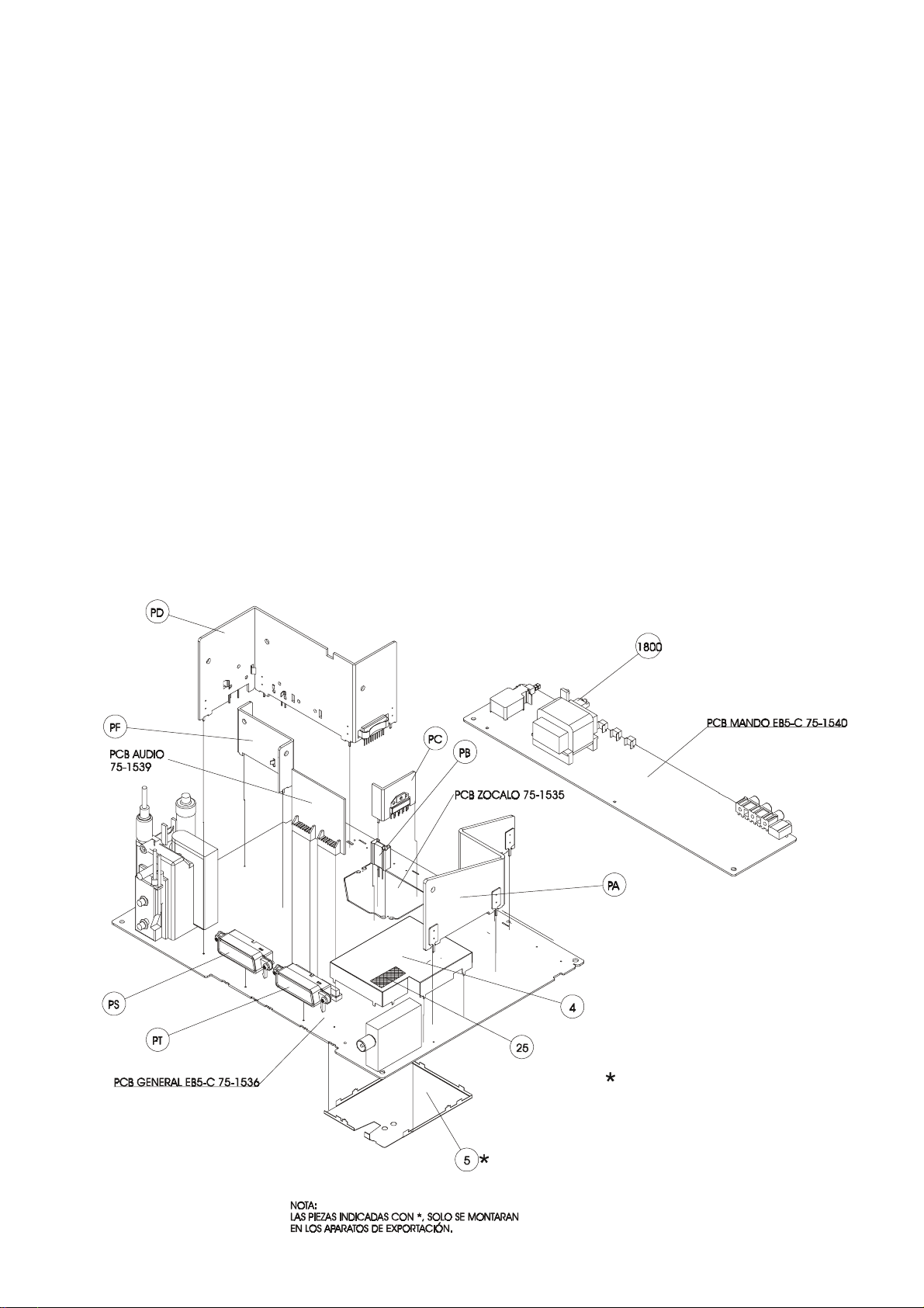
13. CABINET PARTS LIST
13.1. CABINET PARTS LIST OF CHASSIS CE29FFV1-F
Service Manual SM CE29FFV1-F
Ref. No. Part No. Description
YG25 0390320307 Bar Code Label -Chassis
YG4 " 0080113103 COMP. Side IF Shield EB5-C
YG5 0080113202 Copper Side IF Shield EB5-C
YG1800 0200826402 LED Holder
Assy PA (Audio)
IC300 0360517304 TDA 8946 J N1
YR300 0200226108 Heatsink AUDIO EB5-C 25-28-29
YR301 0970200804 Silicon Grease YG6260
YR302 0010106300 Spring CLIP 56379
Assy PD (Deflexión)
IC701 " 0360517007 LA7846N
Q650 0360306708 S 2055 N
Q750 0360309009 BD242BFP
YR650 0200225902 Heatsink Deflection EB5-C 29
YR651 0970200804 Silicon Grease YG6260
YR652 0010106300 Spring CLIP 56379
YR653 0010106300 Spring CLIP 56379
YR654 0010110401 Spring CLIP 56363
Assy PB
D851 0360378905 Schottky FMB-G19L 90V 4ATO220
YR851 0200224905 Heatsink TO-220-F
Localiz. Código Descripción
Assy PF(Fuente alimentación)
Q800 " 0360311302 MOS 2SK2545 600V/6A
YR800 0200225811 Heatsink Power Supply EB5-C
YR801 0010110401 Spring CLIP 56363
Assy PT
S901 0330162702 Scart Connector 21 PIN BLUE
YR901 0200420602 Mounting-BRKT F2WV
YR902 0890115603 Selftapping Screws DIN 7981F 2,9X8
Assy PS
S900 0330162603 Scart Connector 21 PIN BLACK
YR900 0200420602 Mounting-BRKT F2WV
YR903 0890115603 Selftapping Screws DIN 7981F 2,9X8
Assy PC (Zocalo TRC)
IC500 0360514210 TDA 6107 Q/N2
YR500 0200224806 Heatsink RGB EB5-A
YR501 0970200804 Silicon Grease YG6260
YR502 0050709104 Washer
YR503 0890121106 Screw M3X6 FE/ZN DIN 7985
4
Page 6
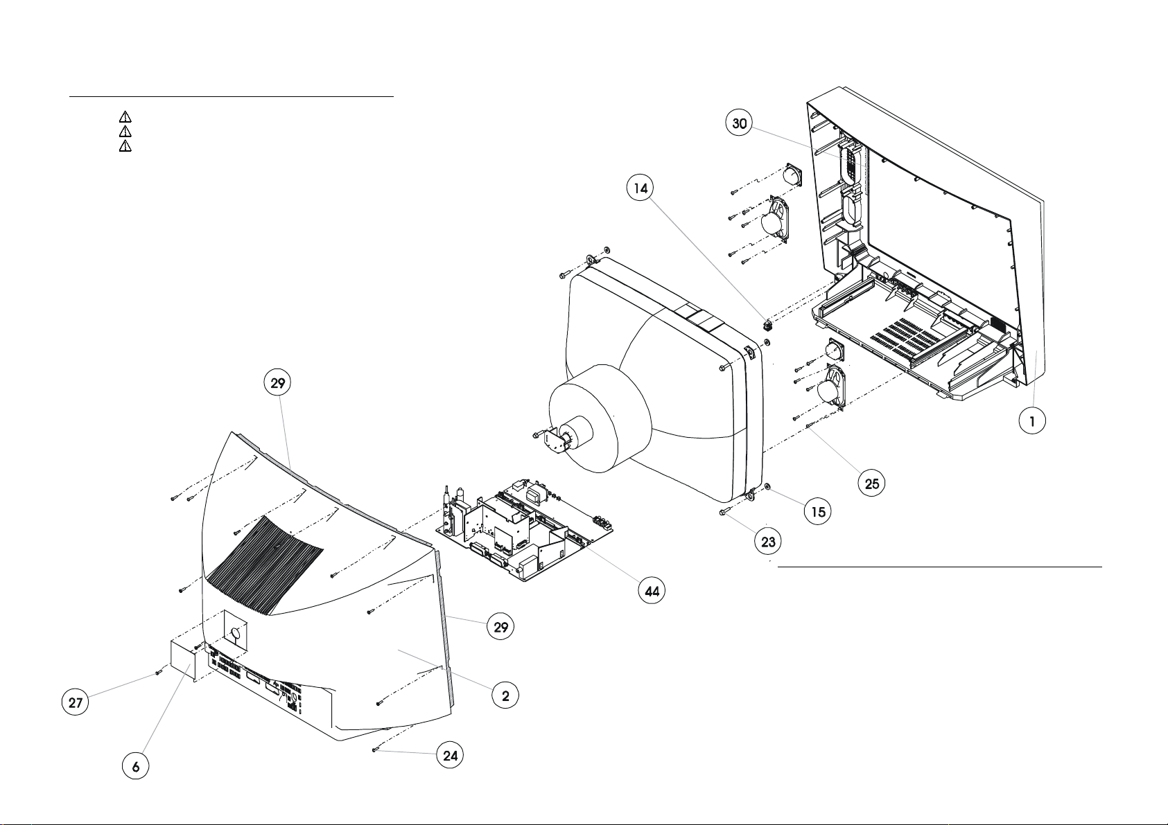
13.2. CABINET PARTS LIST OF CE29FFV1-F
Ref. No. Part. No. Descripti on
YF 1 2700054006 Front Cabinet Assy 29" FLAT ATS
YF 2
YF 6
YF14 0200819910 AC Cord Holder
YF15 0050709005 Spacer Cushion D8RZ
YF18 0010111102 Steel Strapping 21" C2GA
YF23 0890161508 Screw CL 6,1X27
YF24 0890191315 Screw AR 4X15
YF25 0890190903 Screw 4X13
YF27 0890560709 Screw AR. 4,2X13 CINCADO NEGRO
YF37 0890036304 Screw 3,9X9,5
YF44 0200628204 Front RAIL 29" FLAT
0590274809 Back Cover 29" FLAT
0390255305 Rating Place CE29FFV1-F
Service Manual SM CE29FFV1-F
Ref. No. Part. No. Descripti on
(2700054006)
YP 1 0590275806 Cabinet Front 29" FLAT ATS
YP 4 0020125225 SANYO Badge 46,2X13,5/SILVER
YP 5 0340208404 TRANS.DEC.BOARD 29" FLAT
YP 6 0970304002 Rubber Band 600X2800 MM
YP12 0010111003 Key Spring 21" C2GA
YP13 2130010800 Button Power Assy 29" FLAT
YP13-1 0130216500 Button United BASE 29" FLAT
YP13-2 0130216609 Button Power 29" FLAT
YP14 2130010701 Button Base Assy 29"FLAT
YP14-1 0130216401 Button Unit 29" FLAT
YP14-2 0130216302 Button United BASE 29" FLAT
YP16 0200628402 Rail Lateral PCB 29" FLAT
YP19 0590275103 Door 29" FLAT
5
Page 7

Service Manual SM CE29FFV1-F
Ref. No. Part No. Description Ref. No. Part No. Description
14. PARTS LIST
PCB SOCKET TRC
CON_FD 0160220729 Polarized Band 4P 520+6+6
CON_FH 0160230819 Polarized Band Gray 5P. 450+ 6+ 6
CAPACITORS
C500 0270341324 Polyester 100 nF. 10% 250V.
C501 0250322815 Electrolytic 10 µF. 250V.
C503 0240590901 Ceramic 2200 pF +80-20% 2KV.
DIODES
D500 0360007215 BAV21 DIODE
D501 0360007215 BAV21 DIODE
D502 0360007215 BAV21 DIODE
E500 0640705117 Eyelet 2,5-3
FD1 0330144205 Ribbon Wire Holder 4 P.
FH1 0330144304 Ribbon Wire Holder 5 P.
FK 0640300604 Earth Wire 340 mm.
INTEGRATED CIRCUITS
IC500 0360514210 TDA 6107 Q/N2
J117 0470040007 Jumper Lead 0,6 mm.
L502 0090304924 Choke R.F. 470 µH. 10%
L506 0090208307 Coil 75 µH. 10% 1,5 A. R-7,5
PCB04
RESISTORS
R500 0790741409 Solid 1,5 KΩ 10% 1/2W.
R501 0790741409 Solid 1,5 KΩ 10% 1/2W.
R502 0790741409 Solid 1,5 KΩ 10% 1/2W.
R503 0790741409 Solid 1,5 KΩ 10% 1/2W.
R504 0790741409 Solid 1,5 KΩ 10% 1/2W.
R505 0790239008 R.M.G. SMD 1 KΩ T<=5% 0805
R506
R507 0790227003 R.M.G. SMD 100 Ω T<=5% 0805
R508 0790227003 R.M.G. SMD 100 Ω T<=5% 0805
R509 0790227003 R.M.G. SMD 100 Ω T<=5% 0805
R510 0790242002 R.M.G. SMD 1,8 KΩ 5% 1/10W.
R511 0790242002 R.M.G. SMD 1,8 KΩ 5% 1/10W.
R512 0790242002 R.M.G. SMD 1,8 KΩ 5% 1/10W.
ZOCALO
MAIN PCB
CN_FR 0330192402 3P. Connector
CN_G2 0640706503 Blue G2 Wire with two terminals
CN_KV 0330272204 2P. Connector Shield cable 400MM
CN_NA 0330193608 4P. Connector
CN_NB 0330198706 10 P. Connector
CN_NC 0330196601 7P. Connector
CAPACITORS
C100 0230600702 Ceramic SMD 100 nF. 10% 25V.
C102 0230600702 Ceramic SMD 100 nF. 10% 25V.
C103 0230360604 Ceramic SMD 1000 pF. 10% 50V.
C104 0250321072 Electrolytic 10 µF. 63V.
C105 0230480808 Ceramic SMD 10 nF. 10% 50V.
C1051 0250321072 Electrolytic 10 µF. 63V.
C1052 0230600801 Ceramic SMD 100 nF. +80-20% 25V.
C1053 0230480808 Ceramic SMD 10 nF. 10% 50V.
C1054 0230480808 Ceramic SMD 10 nF. 10% 50V.
C1055 0230600702 Ceramic SMD 100 nF. 10% 25V.
C1056 0230600801 Ceramic SMD 100 nF. +80-20% 25V.
C1057 0230600801 Ceramic SMD 100 nF. +80-20% 25V.
C106 0270101322 Polyester 1000 pF. 5% 400V.
C107 0230480808 Ceramic SMD 10 nF. 10% 50V.
C108 0230180309 Ceramic SMD 33 pF. 1% 50V.
C109 0230180309 Ceramic SMD 33 pF. 1% 50V.
0750153520 Socket PCB 5-C
0790535702 Fuse 10 Ω 5% 0,33W.
0330162108 Socket TRC Diameter 22,5 mm.
C112 0230600801 Ceramic SMD 100 nF. +80-20% 25V.
C113 0230360604 Ceramic SMD 1000 pF. 10% 50V.
C114 0230360604 Ceramic SMD 1000 pF. 10% 50V.
C115 " 0230360604 Ceramic SMD 1000 pF. 10% 50V.
C116 " 0230360604 Ceramic SMD 1000 pF. 10% 50V.
C118 0230360604 Ceramic SMD 1000 pF. 10% 50V.
C120 0230480808 Ceramic SMD 10 nF. 10% 50V.
C1251 0230720203 Ceramic SMD 1 µF. 16V. +80-20% 0805
C1252 0230600702 Ceramic SMD 100 nF. 10% 25V.
C190 0230600702 Ceramic SMD 100 nF. 10% 25V.
C191 0230640401 Ceramic SMD 220 nF. 10% 16V.
C200 0250321072 Electrolytic 10 µF. 63V.
C201 0230360604 Ceramic SMD 1000 pF. 10% 50V.
C202 0230360604 Ceramic SMD 1000 pF. 10% 50V.
C203 0230600702 Ceramic SMD 100 nF. 10% 25V.
C204 0230600702 Ceramic SMD 100 nF. 10% 25V.
C207 0250321072 Electrolytic 10 µF. 63V.
C209 0230480808 Ceramic SMD 10 nF. 10% 50V.
C210 0230600801 Ceramic SMD 100 nF. +80-20% 25V.
C250 0230600801 Ceramic SMD 100 nF. +80-20% 25V.
C251 0250461217 Electrolytic 100 µF. 25V.
C252 0270341480 Polyester 100 nF. 10% 63V.
C256 0230480808 Ceramic SMD 10 nF. 10% 50V.
C257 0270341480 Polyester 100 nF. 10% 63V.
C258 0230480808 Ceramic SMD 10 nF. 10% 50V.
C259 0230600801 Ceramic SMD 100 nF. +80-20% 25V.
C260 0250410859 Electrolytic 47 µF. 25V.
C261 0230600801 Ceramic SMD 100 nF. +80-20% 25V.
C300 0250572310 Electrolytic 1000 µF. 25V.
C301 0230600702 Ceramic SMD 100 nF. 10% 25V.
C302 0230360604 Ceramic SMD 1000 pF. 10% 50V.
C303 0230360604 Ceramic SMD 1000 pF. 10% 50V.
C304 0230640401 Ceramic SMD 220 nF. 10% 16V.
C305 0230640401 Ceramic SMD 220 nF. 10% 16V.
C306 0230640401 Ceramic SMD 220 nF. 10% 16V.
C307 0230640401 Ceramic SMD 220 nF. 10% 16V.
C308 0250321072 Electrolytic 10 µF. 63V.
C309 0250321072 Electrolytic 10 µF. 63V.
C310 0240551309 Ceramic 1000 pF. 10% 50V.
C311 0270341324 Polyester 100 nF. 10% 250V.
C312 0270341324 Polyester 100 nF. 10% 250V.
C352 0250410859 Electrolytic 47 µF. 25V.
C353 0250410859 Electrolytic 47 µF. 25V.
C354 0230600801 Ceramic SMD 100 nF. +80-20% 25V.
C355 0230600801 Ceramic SMD 100 nF. +80-20% 25V.
C356 0250500618 Electrolytic 220 µF. 16V.
C357 0250461217 Electrolytic 100 µF. 25V.
C359 0230480808 Ceramic SMD 10 nF. 10% 50V.
C361 0250461217 Electrolytic 100 µF. 25V.
C362 " 0230160400 Ceramic SMD 22 pF. 1% 50V.
C363 " 0230160400 Ceramic SMD 22 pF. 1% 50V.
C364 " 0230240400 Ceramic SMD 100 pF. 5% 50V.
C365 " 0230240400 Ceramic SMD 100 pF. 5% 50V.
C400 0250461217 Electrolytic 100 µF. 25V.
C401 0230600801 Ceramic SMD 100 nF. +80-20% 25V.
C402 0230740003 Ceramic SMD 2,2 µF. 10V. +80-20%
C403 0230520504 Ceramic SMD 22 nF. 10% 50V.
C404 0230640401 Ceramic SMD 220 nF. 10% 16V.
C405 0230360604 Ceramic SMD 1000 pF. 10% 50V.
C406 0230600702 Ceramic SMD 100 nF. 10% 25V.
C407 0230740003 Ceramic SMD 2,2 µF. 10V. +80-20%
C408 0230600702 Ceramic SMD 100 nF. 10% 25V.
C409 0230600702 Ceramic SMD 100 nF. 10% 25V.
C410 0230600702 Ceramic SMD 100 nF. 10% 25V.
C411 0230180309 Ceramic SMD 33 pF. 1% 50V.
C412 0230180309 Ceramic SMD 33 pF. 1% 50V.
C413 0230740003 Ceramic SMD 2,2 µF. 10V. +80-20%
C414 0230520504 Ceramic SMD 22 nF. 10% 50V.
C415 0250461217 Electrolytic 100 µF. 25V.
C416 0230520504 Ceramic SMD 22 nF. 10% 50V.
C417 0230400202 Ceramic SMD 2200 pF. 10% 50V.
C418 " 0230240400 Ceramic SMD 100 pF. 5% 50V.
C419 " 0230200503 Ceramic SMD 47 pF. 5% 50V.
C420 0230680308 Ceramic SMD 470 nF. 10% 16V.
C421 0230440406 Ceramic SMD 4700 pF. 10% 50V.
C422 " 0230240400 Ceramic SMD 100 pF. 5% 50V.
C423 " 0230360604 Ceramic SMD 1000 pF. 10% 50V.
C424 " 0230520504 Ceramic SMD 22 nF. 10% 50V.
6
Page 8

Service Manual SM CE29FFV1-F
Ref. No. Part No. Description Ref. No. Part No. Description
C425 0260340906 Polypropylene 100 nF. 5% 100V.
C426 " 0230360604 Ceramic SMD 1000 pF. 10% 50V.
C427 0230600702 Ceramic SMD 100 nF. 10% 25V.
C428 " 0230240400 Ceramic SMD 100 pF. 5% 50V.
C429 0230240400 Ceramic SMD 100 pF. 5% 50V.
C430 0230240400 Ceramic SMD 100 pF. 5% 50V.
C431 0230240400 Ceramic SMD 100 pF. 5% 50V.
C432 0230360604 Ceramic SMD 1000 pF. 10% 50V.
C433 0230240400 Ceramic SMD 100 pF. 5% 50V.
C434 0230680308 Ceramic SMD 470 nF. 10% 16V.
C435 0250280856 Electrolytic 4,7 µF. 100V.
C436 0230600801 Ceramic SMD 100 nF. +80-20% 25V.
C437 " 0230360604 Ceramic SMD 1000 pF. 10% 50V.
C438 0230360604 Ceramic SMD 1000 pF. 10% 50V.
C439 " 0230480808 Ceramic SMD 10 nF. 10% 50V.
C442 0250321072 Electrolytic 10 µF. 63V.
C443 0230440406 Ceramic SMD 4700 pF. 10% 50V.
C450 " 0230240400 Ceramic SMD 100 pF. 5% 50V.
C451 " 0230240400 Ceramic SMD 100 pF. 5% 50V.
C452 " 0230240400 Ceramic SMD 100 pF. 5% 50V.
C453 0230520504 Ceramic SMD 22 nF. 10% 50V.
C454 0230520504 Ceramic SMD 22 nF. 10% 50V.
C455 0230520504 Ceramic SMD 22 nF. 10% 50V.
C600A 0270341324 Polyester 100 nF. 10% 250V.
C601 0270140122 Polyester 2200 pF. 10% 400V.
C603 0230520504 Ceramic SMD 22 nF. 10% 50V.
C604 0230720203 Ceramic SMD 1 µF. 16V. +80-20% 0805
C650B 0260260500 Polypropylene 22 nF. 3,5% 630V R-15
C651
C652B 0260393004 Polypropylene 300 nF. 5% 250V. R-15
C653
C654C 0260150008 Polypropylene 2,7 nF. 1,6KV 3,5%R-15
C655B 0260268008 Polypropylene 47 nF. 5% 100V.
C656 0250115318 Electrolytic 2,2 µF. 160V. 6,3X11
C657 0240132035 Ceramic 470 pF. 10% 1KV.
C658 0230260705 Ceramic SMD 150 pF. 10% 630V. 1206
C659A 0250504107 Electrolytic 220 µF. 200V. 18x40
C660 0230340408 Ceramic SMD 680 pF. 10% 630V. 1206
C661 0250283835 Electrolytic 4,7 µF. 250V.
C663 0230600702 Ceramic SMD 100 nF. 10% 25V.
C668 0250283835 Electrolytic 4,7 µF. 250V.
C669 0230340408 Ceramic SMD 680 pF. 10% 630V. 1206
C670 0270341324 Polyester 100 nF. 10% 250V.
C674 0230520504 Ceramic SMD 22 nF. 10% 50V.
C675 0230600702 Ceramic SMD 100 nF. 10% 25V.
C680 0250220472 Electrolytic 1 µF. 100V.
C700 0250463718 Electrolytic 100 µF. 50V. 8X11,5
C701 0250463718 Electrolytic 100 µF. 50V. 8X11,5
C703 0270370588 Polyester 180 nF. 10% 63V.
C704 0250463718 Electrolytic 100 µF. 50V. 8X11,5
C710 0270341480 Polyester 100 nF. 10% 63V.
C711 " 0230360604 Ceramic SMD 1000 pF. 10% 50V.
C712 0270220726 Polyester 10 nF. 10% 250V.
C750 0230360604 Ceramic SMD 1000 pF. 10% 50V.
C751 " 0230480808 Ceramic SMD 10 nF. 10% 50V.
C753 0250284023 Electrolytic 4,7 µF. 160V.
C802 0240134767 Ceramic 1000 pF. +-20% 1KV.
C803 0240134767 Ceramic 1000 pF. +-20% 1KV.
C806 0230240400 Ceramic SMD 100 pF. 5% 50V.
C807 0230200503 Ceramic SMD 47 pF. 5% 50V.
C809 0230300709 Ceramic SMD 330 pF. 5% 50V.
C810 0250503661 Electrolytic. 220 µF. 385V. 30X35
C811 0250412970 Electrolytic 47 µF. 50V.
C812
C813 0230360505 Ceramic SMD 1000 pF 5% 100V.0805
C814 0230260309 Ceramic SMD 150 pF. 10% 1KV. 1206
C816
C817 0230300303 Ceramic SMD 330 pF. 10% 630V. 1206
C818 0230300303 Ceramic SMD 330 pF. 10% 630V. 1206
C850 0230280505 Ceramic SMD 220 pF. 10% 1KV. 1206
C851 0230360604 Ceramic SMD 1000 pF. 10% 50V.
C852 0230360604 Ceramic SMD 1000 pF. 10% 50V.
C855 0230600801 Ceramic SMD 100 nF. +80-20% 25V.
C856 0250465218 Electrolytic 100 µF. 200V.
C857 0250601515 Electrolytic 2200 µF. 25V. R- 7,5
C858 0250531910 Electrolytic 470µF. 25V. 10X12,5
C859 0250531910 Electrolytic 470µF. 25V. 10X12,5
C860 0250572419 Electrolytic 1000 µF. 16V.
0260223003 Polypropylene 15 nF. 3,5% 1600V.
0260433065 Polypropylene 820nF. 5% 250V
" 0240136135 Ceramic Capacitor 1000 pF. 20% 4KV.
" 0240136135 Ceramic Capacitor 1000 pF. 20% 4KV.
C861 0250572419 Electrolytic 1000 µF. 16V.
C862 0230640401 Ceramic SMD 220 nF. 10% 16V.
C863 0230360604 Ceramic SMD 1000 pF. 10% 50V.
C866 0230360604 Ceramic SMD 1000 pF. 10% 50V.
C868 0250321072 Electrolytic 10 µF. 63V.
C870 0250321072 Electrolytic 10 µF. 63V.
C871 " 0230360604 Ceramic SMD 1000 pF. 10% 50V.
C874 0250461217 Electrolytic 100 µF. 25V.
C875 0230400202 Ceramic SMD 2200 pF. 10% 50V.
C876 0230360604 Ceramic SMD 1000 pF. 10% 50V.
C900 " 0230320608 Ceramic SMD 470 pF. 5% 50V.
C901 " 0230320608 Ceramic SMD 470 pF. 5% 50V.
C902 " 0230320608 Ceramic SMD 470 pF. 5% 50V.
C903 " 0230320608 Ceramic SMD 470 pF. 5% 50V.
C904 " 0230320608 Ceramic SMD 470 pF. 5% 50V.
C905 " 0230320608 Ceramic SMD 470 pF. 5% 50V.
C906 " 0230320608 Ceramic SMD 470 pF. 5% 50V.
C907 0250321072 Electrolytic 10 µF. 63V.
C913 " 0230240400 Ceramic SMD 100 pF. 5% 50V.
C914 " 0230240400 Ceramic SMD 100 pF. 5% 50V.
C917 " 0230240400 Ceramic SMD 100 pF. 5% 50V.
C918 0230600801 Ceramic SMD 100 nF. +80-20% 25V.
C920 0250321072 Electrolytic 10 µF. 63V.
C921 0250321072 Electrolytic 10 µF. 63V.
C923 0250321072 Electrolytic 10 µF. 63V.
C925 " 0230320608 Ceramic SMD 470 pF. 5% 50V.
C926 0250410859 Electrolytic 47 µF. 25V.
C928 0250410859 Electrolytic 47 µF. 25V.
C930 0250410859 Electrolytic 47 µF. 25V.
C931 0250410859 Electrolytic 47 µF. 25V.
C934 0250410859 Electrolytic 47 µF. 25V.
C935 0250410859 Electrolytic 47 µF. 25V.
C936 0250410859 Electrolytic 47 µF. 25V.
C938 0250321072 Electrolytic 10 µF. 63V.
C939 0230720203 Ceramic SMD 1 µF. 16V. +80-20% 0805
C940 0230720203 Ceramic SMD 1 µF. 16V. +80-20% 0805
DIODES
D102 0360601512 SMD LS4148
D105 0360130819 1N 4148
D106 0360601512 SMD LS4148
D107 0360130819 1N 4148
D108 0360102602 Zener BZX79C3V3
D190 0360130819 1N 4148
D200 0360601512 SMD LS4148
D201 0360601512 SMD LS4148
D250 0360706014 HZT33-02 RE
D251 0360601512 SMD LS4148
D300 0360103204 Zener BZX79C5V1
D301 0360103204 Zener BZX79C5V1
D350 0360601512 SMD LS4148
D351 0360601512 SMD LS4148
D401 0360602411 Zener SMD BZT55C6V2
D402 0360601512 SMD LS4148
D600 0360605604 SMD BAV103 200V 0,25A
D650 0360118608 ERD07-15L
D651 0360007215 BAV21 DIODE
D652A 0360380109 RU3AM
D653 0360377006 ERB44-04
D654 0360601512 SMD LS4148
D655 0360603914 Zener SMD BZT55C33
D658 0360601512 SMD LS4148
D659 0360130819 1N 4148
D660 0360601512 SMD LS4148
D661 0360603914 Zener SMD BZT55C33
D663 0360377006 ERB44-04
D672 0360601512 SMD LS4148
D674 0360603310 Zener SMD BZT55C15
D675 0360601512 SMD LS4148
D683 0360601512 SMD LS4148
D700 0360601512 SMD LS4148
D701 0360130629 1N 4007 RL
D702 0360130819 1N 4148
D703 0360603914 Zener SMD BZT55C33
D704 0360130819 1N 4148
D705 0360135107 Zener BZX79C8V2
D750 0360601512 SMD LS4148
D751 0360105100 Zener BZX79C11
7
Page 9

Service Manual SM CE29FFV1-F
Ref. No. Part No. Description Ref. No. Part No. Description
D752 0360130819 1N 4148
D753 0360130819 1N 4148
D754 0360607006 Zener SMD MMSZ56T1
D800 0360372411 ERC05-10B V1
D801 0360372411 ERC05-10B V1
D802 0360372411 ERC05-10B V1
D803 0360372411 ERC05-10B V1
D804 0360602411 Zener SMD BZT55C6V2
D806 0360376909 ERB44-02
D850 0360374409 RU4B LF-T3
D851 0360378905 Schottky FMB-G19L 90V 4ATO220
D852A 0360379606 1R5GH45 400V 1.5A
D853A 0360379606 1R5GH45 400V 1.5A
D854 0360376909 ERB44-02
D855A 0360376701 Schottky RK 19 V1 90V 1,5A
D857 0360606115 Zener SMD BZT55C4V3
D859 0360606115 Zener SMD BZT55C4V3
D860 0360602213 Zener SMD BZT55C5V1
D861 0360603914 Zener SMD BZT55C33
D862 0360130819 1N 4148
D863 0360104202 Zener BZX79C6V2
D866 0360601512 SMD LS4148
D867 0360130819 1N 4148
D870 0360130819 1N 4148
D871 0360130819 1N 4148
D900 0360602213 Zener SMD BZT55C5V1
D901 0360602213 Zener SMD BZT55C5V1
D902 0360602213 Zener SMD BZT55C5V1
D903 0360602213 Zener SMD BZT55C5V1
D904 0360602213 Zener SMD BZT55C5V1
D905 0360602213 Zener SMD BZT55C5V1
D906 0360602213 Zener SMD BZT55C5V1
D908 0360602213 Zener SMD BZT55C5V1
D909 0360602213 Zener SMD BZT55C5V1
D910 0360602213 Zener SMD BZT55C5V1
D911 0360602213 Zener SMD BZT55C5V1
D912 0360602213 Zener SMD BZT55C5V1
D914 0360602213 Zener SMD BZT55C5V1
D917 0360602213 Zener SMD BZT55C5V1
D918 0360601512 SMD LS4148
D919 0360601512 SMD LS4148
D920 0360601512 SMD LS4148
D921 0360130819 1N 4148
FA 0330270307 2P. Socket
FB1 0330191701 2P. Socket
FB2 0330270109 2 P. Socket
FD 0330144205 Ribbon Wire Holder 4 P.
FF1 0330190000 2P. Connector
FF2 0330270109 2 P. Socket
FH 0330144304 Ribbon Wire Holder 5 P.
INTEGRATED CIRCUITS
IC100 " 0360519003 SAA 5564PS
IC1050 " 0360515605 SMD TDA9181T/N1
IC125 0360712012 SMD M24C08-WMN6T
IC1250 0360517601 SMD TS922IDT
IC300 0360517304 TDA 8946 J N1
IC350 " 0360472609 KA2209B
IC400 " 0360517106 TDA 8879PS N1
IC701 " 0360517007 LA7846N
IC800 0360517205 MC44603ADW SMD
IC801
IC850 0360378764 KA431LZTA TO-92
IC852 0360473409 LD1117V33C TO220
IC853 0360472708 KA78R08TU
IC854 0360472807 KA78R05-STU
IC900 " 0360708804 LA 7221
JO104 0790701106 R.M.G. SMD 0 Ω 1/10W.
JO202 0790701106 R.M.G. SMD 0 Ω 1/10W.
JO252 0790701106 R.M.G. SMD 0 Ω 1/10W.
JO253 0790701106 R.M.G. SMD 0 Ω 1/10W.
JO701 " 0790701106 R.M.G. SMD 0 Ω 1/10W.
JO702 " 0790701106 R.M.G. SMD 0 Ω 1/10W.
J129 0790701106 R.M.G. SMD 0 Ω 1/10W.
J198 0790701106 R.M.G. SMD 0 Ω 1/10W.
0360491203 OPTO TCET1101G
J235 0790701106 R.M.G. SMD 0 Ω 1/10W.
J236 0790701106 R.M.G. SMD 0 Ω 1/10W.
J237 0790701106 R.M.G. SMD 0 Ω 1/10W.
J242 0790701106 R.M.G. SMD 0 Ω 1/10W.
J248 0790701106 R.M.G. SMD 0 Ω 1/10W.
J250 0790701106 R.M.G. SMD 0 Ω 1/10W.
J251 0790701106 R.M.G. SMD 0 Ω 1/10W.
J255 0790701106 R.M.G. SMD 0 Ω 1/10W.
J256 0790701106 R.M.G. SMD 0 Ω 1/10W.
J264 0790701106 R.M.G. SMD 0 Ω 1/10W.
J267 0790701106 R.M.G. SMD 0 Ω 1/10W.
KVBM 0330191701 2P. Socket
K300 0330330002 8P. Connector
K301 0330330002 8P. Connector
K302 0330490301 Connector Assy 10P W/Wires 260 MM
COILS
L100 0090305327 Peaking Coil 10 µH. 10%
L101 0620005801 Ferrite SMD 0805 1K/100MHz 0,2A
L102 0620005801 Ferrite SMD 0805 1K/100MHz 0,2A
L104 0620005801 Ferrite SMD 0805 1K/100MHz 0,2A
L1050 0090319229 Peaking Coil 4,7 µH. 10%
L1051 0620005801 Ferrite SMD 0805 1K/100MHz 0,2A
L1052 0620005801 Ferrite SMD 0805 1K/100MHz 0,2A
L1054 " 0620011502 Ferrite SMD 0603 600 Ω/100MHz
L1055 " 0620011502 Ferrite SMD 0603 600 Ω/100MHz
L250 0090305665 Peaking Coil 4,7 µH 10% I MAX=930MA
L251 0090317140 Peaking Coil 0,39 µH. 20% RADIAL
L252 0090319229 Peaking Coil 4,7 µH. 10%
L300 0090817305 Axial Inductor 12 µH. 10% 1,8A.
L301 " 0620005900 Ferrite SMD 1206 600 Ω/100MH 1,5A
L302 " 0620005900 Ferrite SMD 1206 600 Ω/100MH 1,5A
L303 " 0620005900 Ferrite SMD 1206 600 Ω/100MH 1,5A
L304 " 0620005900 Ferrite SMD 1206 600 Ω/100MH 1,5A
L305 0090817305 Axial Inductor 12 µH. 10% 1,8A.
L350 " 0470040007 Jumper Lead 0,6 mm.
L351 " 0470040007 Jumper Lead 0,6 mm.
L400 0090319229 Peaking Coil 4,7 µH. 10%
L401 0470040007 Jumper Lead 0,6 mm.
L404 " 0620011502 Ferrite SMD 0603 600 Ω/100MHz
L405 0090319229 Peaking Coil 4,7 µH. 10%
L410 0470040007 Jumper Lead 0,6 mm.
L600 0090817206 Axial Inductor 3,3 µH. 10% 2,6A.
L651A 0090804105 Coil 1,3 MH. +-10% 2A. CU20
L652 0090209206 Fixed Lineality Coil DC-15 29" TF
L654 0090817305 Axial Inductor 12 µH. 10% 1,8A.
L656 0090207200 Coil 3,3 MH. 10% 0,175 A.
L661 " 0620005900 Ferrite SMD 1206 600 Ω/100MH 1,5A
L668 " 0620005900 Ferrite SMD 1206 600 Ω/100MH 1,5A
L700 0090305327 Peaking Coil 10 µH. 10%
L703 0090305327 Peaking Coil 10 µH. 10%
L750A 0090502907 E/W Correction Coil 5,5MH. 14X15
L802 " 0620005702 Ferrite Bead 3, 180 Ω/100MHz
L803 0790109300 Carbon 3,3 Ω 5% 1/4W.
L850 0620005116 Pipe Core 3,5X4,5
L851 0620005116 Pipe Core 3,5X4,5
L852 0620005116 Pipe Core 3,5X4,5
L853 0620005116 Pipe Core 3,5X4,5
L854 0620005116 Pipe Core 3,5X4,5
L855 0620005116 Pipe Core 3,5X4,5
L856 0620005702 Ferrite Bead 3, 180 Ω/100MHz
L857 0620005900 Ferrite SMD 1206 600 Ω/100MH 1,5A
L858 0620005900 Ferrite SMD 1206 600 Ω/100MH 1,5A
L859 0620005900 Ferrite SMD 1206 600 Ω/100MH 1,5A
L860 0620005900 Ferrite SMD 1206 600 Ω/100MH 1,5A
L861 0620005702 Ferrite Bead 3, 180 Ω/100MHz
L862 0620005900 Ferrite SMD 1206 600 Ω/100MH 1,5A
L863 0620005900 Ferrite SMD 1206 600 Ω/100MH 1,5A
L864 0090817305 Axial Inductor 12 µH. 10% 1,8A.
L865 0090817305 Axial Inductor 12 µH. 10% 1,8A.
L866 0090319765 Peaking Coil 22 µH. 10% I MAX=130MA
L900 " 0470040007 Jumper Lead 0,6 mm.
L901 " 0470040007 Jumper Lead 0,6 mm.
L902 " 0470040007 Jumper Lead 0,6 mm.
L903 0090319229 Peaking Coil 4,7 µH. 10%
8
Page 10

Service Manual SM CE29FFV1-F
Ref. No. Part No. Description Ref. No. Part No. Description
L905 " 0620011502 Ferrite SMD 0603 600 Ω/100MHz
PCB11
TRANSISTORS
Q100 0360320501 BRT SMD PDTA124ET
Q101 0360320501 BRT SMD PDTA124ET
Q102 0360320303 SMD BC 847 B
Q104 0360320303 SMD BC 847 B
Q105 0360320303 SMD BC 847 B
Q1050 0360320600 BRT SMD PDTC124ET
Q1051 0360320303 SMD BC 847 B
Q106 0360320600 BRT SMD PDTC124ET
Q107 0360321301 SMD BC 857 B
Q1250 0360308803 SMD PMBT2369
Q190 0360320303 SMD BC 847 B
Q200 0360320303 SMD BC 847 B
Q201 0360320600 BRT SMD PDTC124ET
Q202 0360321301 SMD BC 857 B
Q203 0360320303 SMD BC 847 B
Q204 0360320303 SMD BC 847 B
Q207 0360320600 BRT SMD PDTC124ET
Q250 0360320303 SMD BC 847 B
Q251 0360308803 SMD PMBT2369
Q252 0360320501 BRT SMD PDTA124ET
Q253 0360320501 BRT SMD PDTA124ET
Q254 0360320501 BRT SMD PDTA124ET
Q255 0360320410 SMD BF 570
Q257 0360320600 BRT SMD PDTC124ET
Q300 0360320600 BRT SMD PDTC124ET
Q301 0360320600 BRT SMD PDTC124ET
Q350 0360320600 BRT SMD PDTC124ET
Q351 0360320600 BRT SMD PDTC124ET
Q352 0360320600 BRT SMD PDTC124ET
Q400 0360320303 SMD BC 847 B
Q401 0360320303 SMD BC 847 B
Q600 0360309108 2SC2271D-CTV-AE
Q604 0360321301 SMD BC 857 B
Q650 0360306708 S 2055 N
Q651 0360320303 SMD BC 847 B
Q652 0360320303 SMD BC 847 B
Q653 0360308605 KSP 92 TO-92
Q672 0360308506 KSP 42 TO-92
Q673 0360320303 SMD BC 847 B
Q674 0360321301 SMD BC 857 B
Q750 0360309009 BD242BFP
Q751 0360320600 BRT SMD PDTC124ET
Q752 0360308605 KSP 92 TO-92
Q753 0360308605 KSP 92 TO-92
Q754 0360308506 KSP 42 TO-92
Q800 " 0360311302 MOS 2SK2545 600V/6A
Q850 0360311203 MOS 2SK2964 30V/2A SMD
Q851 0360320600 BRT SMD PDTC124ET
Q852 0360311203 MOS 2SK2964 30V/2A SMD
Q853 0360320303 SMD BC 847 B
Q854 0360320303 SMD BC 847 B
Q855 0360320303 SMD BC 847 B
Q856 0360320303 SMD BC 847 B
Q857 0360320600 BRT SMD PDTC124ET
Q858 0360320501 BRT SMD PDTA124ET
Q859 0360320303 SMD BC 847 B
Q861 0360320600 BRT SMD PDTC124ET
Q862 0360308605 KSP 92 TO-92
Q863 0360308506 KSP 42 TO-92
Q900 0360320303 SMD BC 847 B
Q901 0360320303 SMD BC 847 B
Q904 0360308803 SMD PMBT2369
Q905 0360308803 SMD PMBT2369
Q906 0360308803 SMD PMBT2369
Q907 0360321301 SMD BC 857 B
Q908 0360320303 SMD BC 847 B
RESISTORS
R100 0790239008 R.M.G. SMD 1 KΩ T<=5% 0805
R101 0790239008 R.M.G. SMD 1 KΩ T<=5% 0805
R102 0790239008 R.M.G. SMD 1 KΩ T<=5% 0805
R103 0790239008 R.M.G. SMD 1 KΩ T<=5% 0805
R105 0790580203 Metal Film 22 KΩ 1% 0,4W.
0750153629 MAIN PCB EB5-C
R1050 0790752208 R.M.G. SMD 12 KΩ T<=5% 0805
R1051 0790235006 R.M.G. SMD 470 Ω T<=5% 0805
R106 0790138804 Carbon 1 KΩ 5% 1/6W.
R107 0790138804 Carbon 1 KΩ 5% 1/6W.
R108 0790239008 R.M.G. SMD 1 KΩ T<=5% 0805
R109 0790239008 R.M.G. SMD 1 KΩ T<=5% 0805
R110 0790138804 Carbon 1 KΩ 5% 1/6W.
R112 0790141600 Carbon 1,5 KΩ 5% 1/6W.
R113 0790146401 Carbon 3,9 KΩ 5% 1/6W.
R114 0790756001 R.M.G. SMD 24 KΩ 1% 1/8W.
R118 0790239008 R.M.G. SMD 1 KΩ T<=5% 0805
R119 0790239008 R.M.G. SMD 1 KΩ T<=5% 0805
R120 0470040007 Jumper Lead 0,6 mm.
R121 0470040007 Jumper Lead 0,6 mm.
R122 0790237002 R.M.G. SMD 680 Ω T<=5% 0805
R123 0790239008 R.M.G. SMD 1 KΩ T<=5% 0805
R125 0790723506 R.M.G. SMD 47 Ω 1% 1/10W.
R1251 0790131106 Carbon 220 Ω 5% 1/4W.
R1252 0790247001 R.M.G. SMD 4,7 KΩ T<=5% 0805
R1253 0790255004 R.M.G. SMD 22 KΩ T<=5% 0805
R1254 0790767503 R.M.G. SMD 220 KΩ T<=5% 0805
R1255 0790268007 R.M.G. SMD 330 KΩ T<=5% 0805
R1256 0790258503 R.M.G. SMD 43 KΩ T<=5% 0805
R1257 0790256002 R.M.G. SMD 27 KΩ T<=5% 0805
R1258 0790701106 R.M.G. SMD 0 Ω 1/10W.
R126 0790723506 R.M.G. SMD 47 Ω 1% 1/10W.
R1262 0790757603 R.M.G. SMD 33 KΩ T<=5% 0805
R127 0790723506 R.M.G. SMD 47 Ω 1% 1/10W.
R128 0790247001 R.M.G. SMD 4,7 KΩ T<=5% 0805
R129 0790155600 Carbon 22 KΩ 5% 1/6W.
R130 0790741805 R.M.G. SMD 1,5 KΩ T<=5% 0805
R131 0790755706 R.M.G. SMD 23,7 KΩ 1% 1/8W.
R132 0790758304 R.M.G. SMD 39 KΩ 1% 1/8W.
R133 0790255004 R.M.G. SMD 22 KΩ T<=5% 0805
R134 0790255004 R.M.G. SMD 22 KΩ T<=5% 0805
R135 0790239008 R.M.G. SMD 1 KΩ T<=5% 0805
R136 0790138804 Carbon 1 KΩ 5% 1/6W.
R137 0790138804 Carbon 1 KΩ 5% 1/6W.
R138 0790138804 Carbon 1 KΩ 5% 1/6W.
R139 0790255004 R.M.G. SMD 22 KΩ T<=5% 0805
R140 0790239008 R.M.G. SMD 1 KΩ T<=5% 0805
R141 0790126700 Carbon 100 Ω 5% 1/6W.
R142 0790126700 Carbon 100 Ω 5% 1/6W.
R143 0790247001 R.M.G. SMD 4,7 KΩ T<=5% 0805
R144 0790247001 R.M.G. SMD 4,7 KΩ T<=5% 0805
R145 0790138804 Carbon 1 KΩ 5% 1/6W.
R146 0790138804 Carbon 1 KΩ 5% 1/6W.
R148 0790251003 R.M.G. SMD 10 KΩ T<=5% 0805
R149 0790247001 R.M.G. SMD 4,7 KΩ T<=5% 0805
R150 0790130504 Carbon 180 Ω 5% 1/6W
R152 0790749808 R.M.G. SMD 7,5 KΩ T<=5% 0805
R153 0790749808 R.M.G. SMD 7,5 KΩ T<=5% 0805
R156 0790138804 Carbon 1 KΩ 5% 1/6W.
R157 0790143606 Carbon 2,2 KΩ 5% 1/6W.
R158 0790243000 R.M.G. SMD 2,2 KΩ T<=5% 0805
R160 0790263008 R.M.G. SMD 100 KΩ T<=5% 0805
R162 0790255004 R.M.G. SMD 22 KΩ T<=5% 0805
R163 0790255004 R.M.G. SMD 22 KΩ T<=5% 0805
R165 0790239008 R.M.G. SMD 1 KΩ T<=5% 0805
R167 0790239008 R.M.G. SMD 1 KΩ T<=5% 0805
R168 0790251003 R.M.G. SMD 10 KΩ T<=5% 0805
R169 0790251003 R.M.G. SMD 10 KΩ T<=5% 0805
R170 0790251003 R.M.G. SMD 10 KΩ T<=5% 0805
R174 0790126700 Carbon 100 Ω 5% 1/6W.
R179 0470040007 Jumper Lead 0,6 mm.
R182 0790126700 Carbon 100 Ω 5% 1/6W.
R190 0790251003 R.M.G. SMD 10 KΩ T<=5% 0805
R191 0790263008 R.M.G. SMD 100 KΩ T<=5% 0805
R192 0790235006 R.M.G. SMD 470 Ω T<=5% 0805
R193 0790239008 R.M.G. SMD 1 KΩ T<=5% 0805
R194 0790328603 Metal Film 75 Ω 1% 0,6W.
R195 0790239008 R.M.G. SMD 1 KΩ T<=5% 0805
R196 0790328603 Metal Film 75 Ω 1% 0,6W.
R197 0790239008 R.M.G. SMD 1 KΩ T<=5% 0805
9
Page 11

Service Manual SM CE29FFV1-F
Ref. No. Part No. Description Ref. No. Part No. Description
R198 0790328603 Metal Film 75 Ω 1% 0,6W.
R200 0790239008 R.M.G. SMD 1 KΩ T<=5% 0805
R201 0790131106 Carbon 220 Ω 5% 1/4W.
R202 0790239008 R.M.G. SMD 1 KΩ T<=5% 0805
R203 0470040007 Jumper Lead 0,6 mm.
R204 0790864102 R.M.G. SMD 1,2 KΩ T<=5% 0805
R205 0790239008 R.M.G. SMD 1 KΩ T<=5% 0805
R207 " 0790223002 R.M.G. SMD 47 Ω T<=5% 0805
R208 " 0790223002 R.M.G. SMD 47 Ω T<=5% 0805
R209 0790239008 R.M.G. SMD 1 KΩ T<=5% 0805
R210 0790239008 R.M.G. SMD 1 KΩ T<=5% 0805
R211 0790239008 R.M.G. SMD 1 KΩ T<=5% 0805
R212 0790234009 R.M.G. SMD 390 Ω T<=5% 0805
R213 0790235006 R.M.G. SMD 470 Ω T<=5% 0805
R214 0790234009 R.M.G. SMD 390 Ω T<=5% 0805
R215 0790846109 R.M.G. SMD 220 Ω T<=5% 0805
R216 0790239008 R.M.G. SMD 1 KΩ T<=5% 0805
R217 0790235006 R.M.G. SMD 470 Ω T<=5% 0805
R218 0790133607 Carbon 330 Ω 5% 1/6W.
R219 0790133607 Carbon 330 Ω 5% 1/6W.
R220 0790131908 Carbon 220 Ω 5% 1/6W.
R250
R251 0790138804 Carbon 1 KΩ 5% 1/6W.
R252 0790235006 R.M.G. SMD 470 Ω T<=5% 0805
R253 0790263008 R.M.G. SMD 100 KΩ T<=5% 0805
R254 0790126700 Carbon 100 Ω 5% 1/6W.
R255 0790153605 Carbon 15 KΩ 5% 1/6W
R256 0790753909 R.M.G. SMD 15 KΩ T<=5% 0805
R258 0790259006 R.M.G. SMD 47 KΩ T<=5% 0805
R259 0790874101 R.M.G. SMD 2,7 KΩ T<=5% 0805
R260 0790239008 R.M.G. SMD 1 KΩ T<=5% 0805
R261 0790251003 R.M.G. SMD 10 KΩ T<=5% 0805
R262 0790251003 R.M.G. SMD 10 KΩ T<=5% 0805
R263 0790246003 R.M.G. SMD 3,9 KΩ T<=5% 0805
R264 0790753909 R.M.G. SMD 15 KΩ T<=5% 0805
R265 0790701106 R.M.G. SMD 0 Ω 1/10W.
R266 0790242002 R.M.G. SMD 1,8 KΩ 5% 1/10W.
R267 0790874101 R.M.G. SMD 2,7 KΩ T<=5% 0805
R268 0790223002 R.M.G. SMD 47 Ω T<=5% 0805
R269 0790229009 R.M.G. SMD 150 Ω T<=5% 0805
R300 0790750004 Carbon 7,5 KΩ 5% 1/6W.
R301 0790245005 R.M.G. SMD 3,3 KΩ T<=5% 0805
R302 0790750004 Carbon 7,5 KΩ 5% 1/6W.
R303 0790245005 R.M.G. SMD 3,3 KΩ T<=5% 0805
R304 0790251003 R.M.G. SMD 10 KΩ T<=5% 0805
R305 0790251003 R.M.G. SMD 10 KΩ T<=5% 0805
R309 0790239008 R.M.G. SMD 1 KΩ T<=5% 0805
R310
R311 0790111207 Carbon 4,7 Ω 5% 1/4W.
R312 0790111207 Carbon 4,7 Ω 5% 1/4W.
R350 0790123103 Carbon 47 Ω 5% 1/4W.
R351 0790123103 Carbon 47 Ω 5% 1/4W.
R352 0790711204 R.M.G. SMD 4,7 Ω T<=5% 0805
R353 0790711204 R.M.G. SMD 4,7 Ω T<=5% 0805
R354 0790318000 R.M.G. SMD 10 Ω T<=5% 0805
R355 0790247001 R.M.G. SMD 4,7 KΩ T<=5% 0805
R356 0790247001 R.M.G. SMD 4,7 KΩ T<=5% 0805
R357 0790255004 R.M.G. SMD 22 KΩ T<=5% 0805
R359 0790741805 R.M.G. SMD 1,5 KΩ T<=5% 0805
R360 0790159503 Carbon 47 KΩ 5% 1/6W
R361 0790741805 R.M.G. SMD 1,5 KΩ T<=5% 0805
R362 0790259006 R.M.G. SMD 47 KΩ T<=5% 0805
R363 0790239008 R.M.G. SMD 1 KΩ T<=5% 0805
R364 0790239008 R.M.G. SMD 1 KΩ T<=5% 0805
R400 0790126700 Carbon 100 Ω 5% 1/6W.
R401 0790126700 Carbon 100 Ω 5% 1/6W.
R402 0790151500 Carbon 10 KΩ 5% 1/6W.
R403 0790227003 R.M.G. SMD 100 Ω T<=5% 0805
R404 0790227003 R.M.G. SMD 100 Ω T<=5% 0805
R405 0790227003 R.M.G. SMD 100 Ω T<=5% 0805
R408 0790126700 Carbon 100 Ω 5% 1/6W.
R409 0790126700 Carbon 100 Ω 5% 1/6W.
R410 0790126700 Carbon 100 Ω 5% 1/6W.
R411 0790126700 Carbon 100 Ω 5% 1/6W.
0790579437 Metal Film 18 KΩ 5% 2W.
0790200000 Fuse 0,1 Ω 10% 0,5W
R412 0790243000 R.M.G. SMD 2,2 KΩ T<=5% 0805
R413 0790227003 R.M.G. SMD 100 Ω T<=5% 0805
R414 0790756308 Carbon 27 KΩ 5% 1/6W.
R415 0790239008 R.M.G. SMD 1 KΩ T<=5% 0805
R416 0790288005 R.M.G. SMD 10 MΩ 5% 1/10W.
R417 0790288005 R.M.G. SMD 10 MΩ 5% 1/10W.
R418 0790753909 R.M.G. SMD 15 KΩ T<=5% 0805
R419 0790753909 R.M.G. SMD 15 KΩ T<=5% 0805
R420 0790251003 R.M.G. SMD 10 KΩ T<=5% 0805
R423 0790263008 R.M.G. SMD 100 KΩ T<=5% 0805
R424 0790757603 R.M.G. SMD 33 KΩ T<=5% 0805
R425 0790180707 R.M.G. SMD 2,2 MΩ T<=5% 0805
R426 0790758304 R.M.G. SMD 39 KΩ 1% 1/8W.
R427 0790137707 Carbon 680 Ω 5% 1/6W
R428 0790123400 Carbon 47 Ω 5% 1/6W.
R429 0790227003 R.M.G. SMD 100 Ω T<=5% 0805
R431 0790126700 Carbon 100 Ω 5% 1/6W.
R432 0790126700 Carbon 100 Ω 5% 1/6W.
R433 0790126700 Carbon 100 Ω 5% 1/6W.
R440 0790184402 Carbon 4,7 MΩ 5% 1/4W.
R442 0790239008 R.M.G. SMD 1 KΩ T<=5% 0805
R443 0790239008 R.M.G. SMD 1 KΩ T<=5% 0805
R444 0790227003 R.M.G. SMD 100 Ω T<=5% 0805
R450 " 0790126700 Carbon 100 Ω 5% 1/6W.
R451 " 0790126700 Carbon 100 Ω 5% 1/6W.
R452 " 0790126700 Carbon 100 Ω 5% 1/6W.
R453 0790126700 Carbon 100 Ω 5% 1/6W.
R454 0790126700 Carbon 100 Ω 5% 1/6W.
R455 0790126700 Carbon 100 Ω 5% 1/6W.
R456 0790126700 Carbon 100 Ω 5% 1/6W.
R457 0790227003 R.M.G. SMD 100 Ω T<=5% 0805
R458 0790126700 Carbon 100 Ω 5% 1/6W.
R459 0790126700 Carbon 100 Ω 5% 1/6W.
R601A 0790147300 Carbon 4,7 KΩ 5% 1/2W.
R602 0790248009 R.M.G. SMD 5,6 KΩ T<=5% 0805
R603
R604 0790239008 R.M.G. SMD 1 KΩ T<=5% 0805
R605 0790243000 R.M.G. SMD 2,2 KΩ T<=5% 0805
R606 0470040007 Jumper Lead 0,6 mm.
R607 0790223002 R.M.G. SMD 47 Ω T<=5% 0805
R608
R612
R651 0790331201 Metal Film 120 Ω 5% 2W.
R652 0790559223 Metal Film 820 Ω 5% 1W.
R653 0470040007 Jumper Lead 0,6 mm.
R654 0790701106 R.M.G. SMD 0 Ω 1/10W.
R655 0790527014 Metal Film 1,8 Ω 5% 2W.
R656 0790260004 R.M.G. SMD 56 KΩ T<=5% 0805
R657 0790259006 R.M.G. SMD 47 KΩ T<=5% 0805
R658 0790259006 R.M.G. SMD 47 KΩ T<=5% 0805
R660 0790251003 R.M.G. SMD 10 KΩ T<=5% 0805
R661 0790251003 R.M.G. SMD 10 KΩ T<=5% 0805
R662 0790131908 Carbon 220 Ω 5% 1/6W.
R663 0790151500 Carbon 10 KΩ 5% 1/6W.
R666A 0790512313 Metal Film 0,33 Ω 5% 1W.
R667 0790239008 R.M.G. SMD 1 KΩ T<=5% 0805
R668 0790163000 Carbon 100 KΩ 5% 1/6W
R669 0790255004 R.M.G. SMD 22 KΩ T<=5% 0805
R670 0790701106 R.M.G. SMD 0 Ω 1/10W.
R675 0470040007 Jumper Lead 0,6 mm.
R676 0790263008 R.M.G. SMD 100 KΩ T<=5% 0805
R677 0790159503 Carbon 47 KΩ 5% 1/6W
R678 0790888101 R.M.G. SMD 9,1 KΩ T<=5% 0805
R679 0790156103 Carbon 27 KΩ 5% 1/4W.
R680 0790263008 R.M.G. SMD 100 KΩ T<=5% 0805
R681 0790255103 Metal GL. RES. 22 KΩ 1% 1/10W.
R682 0790259006 R.M.G. SMD 47 KΩ T<=5% 0805
R683 0790259006 R.M.G. SMD 47 KΩ T<=5% 0805
R684 0790143606 Carbon 2,2 KΩ 5% 1/6W.
R685 0790260004 R.M.G. SMD 56 KΩ T<=5% 0805
R688 0790767503 R.M.G. SMD 220 KΩ T<=5% 0805
R689 0790151500 Carbon 10 KΩ 5% 1/6W.
R690 0790255004 R.M.G. SMD 22 KΩ T<=5% 0805
R691 0790127104 Carbon 100 Ω 5% 1/4W.
0790344030 Metal Film 1,2 KΩ 5% 2W.
0790578132 Metal Film 15 KΩ 5% 2W.
0790518807 Metal Film 0,56 Ω 5% 1,2W.__
10
Page 12

Service Manual SM CE29FFV1-F
Ref. No. Part No. Description Ref. No. Part No. Description
R694 0790247001 R.M.G. SMD 4,7 KΩ T<=5% 0805
R696 0790261002 R.M.G. SMD 68 KΩ T<=5% 0805
R698 0790145106 Carbon 3,3 KΩ 5% 1/6W
R700 0790151500 Carbon 10 KΩ 5% 1/6W.
R702 0790522601 Metal Film 0,82 Ω 5% 0,6W.
R703 0790526701 Metal Film 1,5 Ω 1% 0,6W.
R705A 0790139315 Carbon 1 KΩ 5% 1/2W.
R706 0790251003 R.M.G. SMD 10 KΩ T<=5% 0805
R708 0790251003 R.M.G. SMD 10 KΩ T<=5% 0805
R711 0790349203 Metal Film 1,82 KΩ 1% 0,4W.
R712 0790349203 Metal Film 1,82 KΩ 1% 0,4W.
R750A
R751 0790251003 R.M.G. SMD 10 KΩ T<=5% 0805
R752 0790248009 R.M.G. SMD 5,6 KΩ T<=5% 0805
R753 0790163000 Carbon 100 KΩ 5% 1/6W
R754 0790586309 Metal Film 68 KΩ 1% 0,6W
R755 0790239008 R.M.G. SMD 1 KΩ T<=5% 0805
R756 0790127104 Carbon 100 Ω 5% 1/4W.
R757 0790255004 R.M.G. SMD 22 KΩ T<=5% 0805
R758 0790255004 R.M.G. SMD 22 KΩ T<=5% 0805
R759 0790155600 Carbon 22 KΩ 5% 1/6W.
R760A
R761 0790138804 Carbon 1 KΩ 5% 1/6W.
R762 0790251003 R.M.G. SMD 10 KΩ T<=5% 0805
R763 0790126700 Carbon 100 Ω 5% 1/6W.
R803 0790255004 R.M.G. SMD 22 KΩ T<=5% 0805
R804 0790741805 R.M.G. SMD 1,5 KΩ T<=5% 0805
R805 0790590111 Metal Film 150 KΩ 5% 2W.
R806 0790255004 R.M.G. SMD 22 KΩ T<=5% 0805
R808 0790243000 R.M.G. SMD 2,2 KΩ T<=5% 0805
R810
R811
R812
R813 0790764005 R.M.G. SMD 120 KΩ T<=5% 0805
R814 0790151203 R.M.G. SMD 11 KΩ 5% 1/10W 0805
R815 0790153605 Carbon 15 KΩ 5% 1/6W
R816 0790138002 Carbon 750 Ω 5% 1/4W.
R817 0790121206 Carbon 33 Ω 5% 1/4W.
R818 0790135206 Carbon 470 Ω 5% 1/4W.
R819 0790247001 R.M.G. SMD 4,7 KΩ T<=5% 0805
R820 0790206502 Metal Film 0,36 Ω 5% 1,2W.
R821 0790206502 Metal Film 0,36 Ω 5% 1,2W.
R851 0790239008 R.M.G. SMD 1 KΩ T<=5% 0805
R852 0790247001 R.M.G. SMD 4,7 KΩ T<=5% 0805
R853 0790237002 R.M.G. SMD 680 Ω T<=5% 0805
R854 0790239008 R.M.G. SMD 1 KΩ T<=5% 0805
R855 0790594204 Metal Film 280 KΩ 1% 0,6W
R856 0790353007 M.G.R. SMD 4,87 KΩ 1% 1/8W 0805
R857 0790592307 Metal Film 220 KΩ 1% 0,6W.
R858 0790239008 R.M.G. SMD 1 KΩ T<=5% 0805
R859 0790256002 R.M.G. SMD 27 KΩ T<=5% 0805
R860 0790363105 R.M.G. SMD 18 KΩ T<=5% 0805
R861 0790255004 R.M.G. SMD 22 KΩ T<=5% 0805
R862 0790255004 R.M.G. SMD 22 KΩ T<=5% 0805
R863 0790251003 R.M.G. SMD 10 KΩ T<=5% 0805
R864 0790251003 R.M.G. SMD 10 KΩ T<=5% 0805
R865 0790251003 R.M.G. SMD 10 KΩ T<=5% 0805
R866 0790239008 R.M.G. SMD 1 KΩ T<=5% 0805
R867 0790741805 R.M.G. SMD 1,5 KΩ T<=5% 0805
R869 0790363105 R.M.G. SMD 18 KΩ T<=5% 0805
R870 0790127104 Carbon 100 Ω 5% 1/4W.
R871 0790767008 Carbon 220 KΩ 5% 1/6W.
R872 0790178602 Carbon 1,6 MΩ 5% 1/6W.
R873 0790251003 R.M.G. SMD 10 KΩ T<=5% 0805
R874 0790255004 R.M.G. SMD 22 KΩ T<=5% 0805
R876 0790259006 R.M.G. SMD 47 KΩ T<=5% 0805
R877 0790239008 R.M.G. SMD 1 KΩ T<=5% 0805
R878 0790000103 SMD 0,33 Ω 5% 0,25W.
R879 0790000103 SMD 0,33 Ω 5% 0,25W.
R880 0790597108 Metal Film 470 KΩ 5% 0,6W
R881 0790155600 Carbon 22 KΩ 5% 1/6W.
R885 0790239008 R.M.G. SMD 1 KΩ T<=5% 0805
R886 0790255004 R.M.G. SMD 22 KΩ T<=5% 0805
R900 0790026207 Carbon 560 Ω 5% 1/4W.
0790539662 Metal Film 22 Ω 5% 2W.
0790536437 Metal Film 10 Ω 5% 2W.
0790513014 Fuse 0,33 Ω 5% 0,5W.
0790609002 Metal GLAZE RES. 8,2 MΩ 5% 1W.
0470040007 Jumper Lead 0,6 mm.
R901 0790126700 Carbon 100 Ω 5% 1/6W.
R902 0790036305 Carbon 2,2 KΩ 5% 1/4W.
R903 0790026207 Carbon 560 Ω 5% 1/4W.
R904 0790126700 Carbon 100 Ω 5% 1/6W.
R905 0790036305 Carbon 2,2 KΩ 5% 1/4W.
R906 0790155105 Carbon 22 KΩ 5% 1/4W.
R907 0790749402 R.M.G. SMD 6,8 KΩ T<=5% 0805
R908 0790225502 R.M.G. SMD 75 Ω T<=5% 0805
R909 0790725907 SMD 75 Ω 5% 0,25W. 1206
R910 0790155105 Carbon 22 KΩ 5% 1/4W.
R911 0790749402 R.M.G. SMD 6,8 KΩ T<=5% 0805
R912 0790026207 Carbon 560 Ω 5% 1/4W.
R913 0790227003 R.M.G. SMD 100 Ω T<=5% 0805
R914 0790026207 Carbon 560 Ω 5% 1/4W.
R915 0790227003 R.M.G. SMD 100 Ω T<=5% 0805
R916 0790036305 Carbon 2,2 KΩ 5% 1/4W.
R917 0790036305 Carbon 2,2 KΩ 5% 1/4W.
R918 0790141600 Carbon 1,5 KΩ 5% 1/6W.
R919 0790141600 Carbon 1,5 KΩ 5% 1/6W.
R920 0790141600 Carbon 1,5 KΩ 5% 1/6W.
R921 0790134001 Carbon 390 Ω 5% 1/6W
R922 0790225502 R.M.G. SMD 75 Ω T<=5% 0805
R923 0790225502 R.M.G. SMD 75 Ω T<=5% 0805
R924 0790225502 R.M.G. SMD 75 Ω T<=5% 0805
R925 0790225502 R.M.G. SMD 75 Ω T<=5% 0805
R926 0790125900 Carbon 75 Ω 5% 1/6W.
R927 0790725907 SMD 75 Ω 5% 0,25W. 1206
R928 0790146401 Carbon 3,9 KΩ 5% 1/6W.
R929 0790246003 R.M.G. SMD 3,9 KΩ T<=5% 0805
R930 0790246003 R.M.G. SMD 3,9 KΩ T<=5% 0805
R931 0790227003 R.M.G. SMD 100 Ω T<=5% 0805
R932 0790227003 R.M.G. SMD 100 Ω T<=5% 0805
R933 0790227003 R.M.G. SMD 100 Ω T<=5% 0805
R934 0790135701 Carbon 470 Ω 5% 1/6W.
R935 0790550701 Metal Film 150 Ω 1% 0,6W.
R936 0790135701 Carbon 470 Ω 5% 1/6W.
R938 0470040007 Jumper Lead 0,6 mm.
R939 0470040007 Jumper Lead 0,6 mm.
R940 0790225502 R.M.G. SMD 75 Ω T<=5% 0805
R941 0790328603 Metal Film 75 Ω 1% 0,6W.
R942 0790239008 R.M.G. SMD 1 KΩ T<=5% 0805
R943 0790239008 R.M.G. SMD 1 KΩ T<=5% 0805
R945 0790225502 R.M.G. SMD 75 Ω T<=5% 0805
R946 0790225502 R.M.G. SMD 75 Ω T<=5% 0805
R947 0790225502 R.M.G. SMD 75 Ω T<=5% 0805
R948 0790251003 R.M.G. SMD 10 KΩ T<=5% 0805
R949 0790239008 R.M.G. SMD 1 KΩ T<=5% 0805
R950 0790255004 R.M.G. SMD 22 KΩ T<=5% 0805
SF200 " 0090413204 SAW Filter K3953M
SF201 " 0090414806 SAW Filter K9456M
SF250 " 0090413600 Ceramic Filter MKT40.4MA110P
S900 0330162603 Scart Connector 21 PIN BLACK
S901 0330162702 Scart Connector 21 PIN BLUE
TUNER
TU250 " 0850102617 Tuner UV1315/AI-2
TRANSFORMERS
T600 0940200801 Driver Transformer 800T/20T
T650C
T650CF
T800
VR850 0770512408 VR 470 Ω
X100 0090122706 Quartz Crystal 12 MHz 20pF
X400 0090122706 Quartz Crystal 12 MHz 20pF
0940109903 FBT 29" MBO EB5-C HFT2307
0330160508 Focus Wire FBT SANYO
" 0930108105 Switch Mode Transf. EB5-C 29" 10770080
11
Page 13

Service Manual SM CE29FFV1-F
Ref. No. Part No. Description Ref. No. Part No. Description
AUDIO PCB
CAPACITORS
C1301 0230720203 Ceramic SMD 1 µF. 16V. +80-20% 0805
C1302 0230480808 Ceramic SMD 10 nF. 10% 50V.
C1303 0230600702 Ceramic SMD 100 nF. 10% 25V.
C1304 0230480808 Ceramic SMD 10 nF. 10% 50V.
C1305 0230720203 Ceramic SMD 1 µF. 16V. +80-20% 0805
C1306 0230480808 Ceramic SMD 10 nF. 10% 50V.
C1307 0230720203 Ceramic SMD 1 µF. 16V. +80-20% 0805
C1308 0230720203 Ceramic SMD 1 µF. 16V. +80-20% 0805
C1309 0230720203 Ceramic SMD 1 µF. 16V. +80-20% 0805
C1310 0230720203 Ceramic SMD 1 µF. 16V. +80-20% 0805
C1311 0230720203 Ceramic SMD 1 µF. 16V. +80-20% 0805
C1312 0230720203 Ceramic SMD 1 µF. 16V. +80-20% 0805
C1313 " 0230240400 Ceramic SMD 100 pF. 5% 50V.
C1314 " 0230240400 Ceramic SMD 100 pF. 5% 50V.
C1319 0230720203 Ceramic SMD 1 µF. 16V. +80-20% 0805
C1320 0250410859 Electrolytic 47 µF. 25V.
C1323 0250410859 Electrolytic 47 µF. 25V.
C1324 0230320707 Ceramic SMD 470 pF. 10% 50V.
C1326 0230320707 Ceramic SMD 470 pF. 10% 50V.
C1328 0230320707 Ceramic SMD 470 pF. 10% 50V.
C1330 0230320707 Ceramic SMD 470 pF. 10% 50V.
C1332 0250410859 Electrolytic 47 µF. 25V.
C1333 0230480808 Ceramic SMD 10 nF. 10% 50V.
C1334 0230480808 Ceramic SMD 10 nF. 10% 50V.
C1335 0230480808 Ceramic SMD 10 nF. 10% 50V.
C1336 0230480808 Ceramic SMD 10 nF. 10% 50V.
C1338 0230480808 Ceramic SMD 10 nF. 10% 50V.
C1339 0230480808 Ceramic SMD 10 nF. 10% 50V.
C1340 0230480808 Ceramic SMD 10 nF. 10% 50V.
C1341 0250321072 Electrolytic 10 µF. 63V.
C1342 0230480808 Ceramic SMD 10 nF. 10% 50V.
C1343 0230720203 Ceramic SMD 1 µF. 16V. +80-20% 0805
C1344 0230720203 Ceramic SMD 1 µF. 16V. +80-20% 0805
C1380 0230600702 Ceramic SMD 100 nF. 10% 25V.
C1381 0250410859 Electrolytic 47 µF. 25V.
C1382 0250280856 Electrolytic 4,7 µF. 100V.
C1383 0250220472 Electrolytic 1 µF. 100V.
C1384 0270241136 Polyester 15 nF. 5% 63V.
C1385 0230320608 Ceramic SMD 470 pF. 5% 50V.
C1386 0250280856 Electrolytic 4,7 µF. 100V.
C1387 0250280856 Electrolytic 4,7 µF. 100V.
C1388 0270222037 Polyester 10 nF. 5% 63V.
C1389 0270311137 Polyester 56 nF. 5% 63V.
C1390 0250410859 Electrolytic 47 µF. 25V.
C1391 0270311137 Polyester 56 nF. 5% 63V.
C1392 0270222037 Polyester 10 nF. 5% 63V.
C1393 0250280856 Electrolytic 4,7 µF. 100V.
C1394 0250280856 Electrolytic 4,7 µF. 100V.
C1395 0230320608 Ceramic SMD 470 pF. 5% 50V.
C1396 0270241136 Polyester 15 nF. 5% 63V.
C1397 0250220472 Electrolytic 1 µF. 100V.
C1398 0250280856 Electrolytic 4,7 µF. 100V.
C1399 0230600702 Ceramic SMD 100 nF. 10% 25V.
DIODES
D1301 0360602213 Zener SMD BZT55C5V1
D1302 0360602213 Zener SMD BZT55C5V1
D1303 0360602213 Zener SMD BZT55C5V1
D1304 0360602213 Zener SMD BZT55C5V1
INTEGRATED CIRCUITS
IC1300 0360517700 TDA 9875AH V2
IC1380 0360517403 BA3880AFS
K1300 0330330101 8P. Connector
K1301 0330330101 8P. Connector
K1302 0330198706 10 P. Connector
L1304 0620005801 Ferrite SMD 0805 1K/100MHz 0,2A
L1305 0090316506 Peaking Coil 2,2 µH.10% RADIAL
L1306 0620005801 Ferrite SMD 0805 1K/100MHz 0,2A
L1307 0620005801 Ferrite SMD 0805 1K/100MHz 0,2A
L1308 0090316506 Peaking Coil 2,2 µH.10% RADIAL
L1309 0620011502 Ferrite SMD 0603 600 Ω/100MHz
L1310 0620005801 Ferrite SMD 0805 1K/100MHz 0,2A
PCB14
TRANSISTORS
Q1300 0360320600 BRT SMD PDTC124ET
Q1301 0360320600 BRT SMD PDTC124ET
RESISTORS
R1300 0790227003 R.M.G. SMD 100 Ω T<=5% 0805
R1301 0790227003 R.M.G. SMD 100 Ω T<=5% 0805
R1302 0790251003 R.M.G. SMD 10 KΩ T<=5% 0805
R1303 0790255004 R.M.G. SMD 22 KΩ T<=5% 0805
R1304 0790701106 R.M.G. SMD 0 Ω 1/10W.
R1305 0790701106 R.M.G. SMD 0 Ω 1/10W.
R1306 0790247001 R.M.G. SMD 4,7 KΩ T<=5% 0805
R1309 0790239008 R.M.G. SMD 1 KΩ T<=5% 0805
R1310 0790752208 R.M.G. SMD 12 KΩ T<=5% 0805
R1311 0790752208 R.M.G. SMD 12 KΩ T<=5% 0805
R1312 0790752208 R.M.G. SMD 12 KΩ T<=5% 0805
R1313 0790752208 R.M.G. SMD 12 KΩ T<=5% 0805
R1314 0790752208 R.M.G. SMD 12 KΩ T<=5% 0805
R1315 0790752208 R.M.G. SMD 12 KΩ T<=5% 0805
R1316 0790232003 R.M.G. SMD 270 Ω T<=5% 0805
R1321 0790247001 R.M.G. SMD 4,7 KΩ T<=5% 0805
X1300 0090121906 Quartz Crystal 24.576 MHz
0750153926 AUDIO PCB EB5-C
PWB ASSY FRONT
CN_NAF 0330430000 Connector Assy 4P W/WireS 90 mm.
CN_NBF 0330490103 Connector Assy 10P W/WireS 90 mm.
CN_NCF 0330460007 Connector Assy 7P W/WireS 90 mm.
CAPACITORS
C1800
C1801
C1810 0250321072 Electrolytic 10 µF. 63V.
C1830 " 0240143214 Ceramic 10 nF. +80-20% 63V.
C1831 " 0240143214 Ceramic 10 nF. +80-20% 63V.
C1832 0270341480 Polyester 100 nF. 10% 63V.
C1840 " 0240131417 Ceramic 470 pF. 10% 100V.
C1841 0240131417 Ceramic 470 pF. 10% 100V.
C1843 " 0240131417 Ceramic 470 pF. 10% 100V.
C1844 0240131417 Ceramic 470 pF. 10% 100V.
C1847 0250321072 Electrolytic 10 µF. 63V.
C1849 " 0240131417 Ceramic 470 pF. 10% 100V.
DIODES
D1800 0360126205 Red/Green 3 mm.
D1801 0360130819 1N 4148
D1840 0360103204 Zener BZX79C5V1
D1841 0360103204 Zener BZX79C5V1
E1800 0640705117 Eyelet 2,5-3
E1801 0640705117 Eyelet 2,5-3
E1802 0640705117 Eyelet 2,5-3
E1803 0640705117 Eyelet 2,5-3
E1804 0640705117 Eyelet 2,5-3
E1805 0640705117 Eyelet 2,5-3
E1806 0640705117 Eyelet 2,5-3
E1807 0640705117 Eyelet 2,5-3
E1808 0640705117 Eyelet 2,5-3
E1809 0640705117 Eyelet 2,5-3
" 0260380324 Polypropilene 220 nF 10% 275V.
" 0260341003 Polypropylene 100 nF. 20% 275V
COILS
L1300 0620011502 Ferrite SMD 0603 600 Ω/100MHz
L1301 0620011502 Ferrite SMD 0603 600 Ω/100MHz
L1302 0620011502 Ferrite SMD 0603 600 Ω/100MHz
L1303 0620011502 Ferrite SMD 0603 600 Ω/100MHz
FAF 0330271305 2P. Socket W/ CLIP
FCF 0330270307 2P. Socket
FEF 0330271305 2P. Socket W/ CLIP
F1800
0330110503 Fuse T 2 A./250V. TIME-LAG
12
Page 14

Service Manual SM CE29FFV1-F
Ref. No. Part No. Description Ref. No. Part No. Description
KVAF 0330191701 2P. Socket
COILS
L1800 "
L1801 0090413808 pFC Coil 65 MH 1,05A 47X44X39
L1830 " 0090319765 Peaking Coil 22 µH. 10% I MAX=130MA
L1831 " 0090319765 Peaking Coil 22 µH. 10% I MAX=130MA
L1840 " 0090315029 Peaking Coil 10 µH. 10%
L1841 " 0090315029 Peaking Coil 10 µH. 10%
L1842 " 0090315029 Peaking Coil 10 µH. 10%
PCB20
PF1800 0760100701 Fuse Terminal Taped
PL1802 0130209414 Push Switch L-3,85MM
PL1803 0130209414 Push Switch L-3,85MM
PL1804 0130209414 Push Switch L-3,85MM
PL1805 0130209414 Push Switch L-3,85MM
PT1801
RE1800 0090117003 Degaussing RELE 250V/5A 5V/100_Ω
RI1800 0600123509 Infrared Receiver SPS-443-1-E
RESISTORS
R1800
R1801
R1802 0790135206 Carbon 470 Ω 5% 1/4W.
R1812 0790357024 Metal Film 7,50 KΩ 1% 0,4W.
R1813 0790360705 Metal Film 12,0 KΩ 1% 0,4W.
R1814 0790581201 Thin Film Res. 33,2 KΩ 1% 0,6W
R1815 0790583306 Metal Film 51,1 KΩ 1% 0,4W.
R1840 0790036305 Carbon 2,2 KΩ 5% 1/4W.
R1841 0790036305 Carbon 2,2 KΩ 5% 1/4W.
R1842 0790125702 Carbon 75 Ω 5% 1/4W.
0090412206 Mains Filter 2X27 MH 250VAC 1A
0750154015 PWB Front EB5-C
0810101907 P.T.C. 18 Ω
0790180111 Carbon 2,2 MΩ 5% 1/2W.
0790184113 Carbon 4,7 MΩ 5% 1/2W.
PMAT 0970806907 Silicon Grease KS-650N
SC001 0170200406 Shield Mesh 2 mm.
SC1001 0010110708 Grounding Spring
SPK1 0030118418 Speaker 8 Ω 12W. 120X60
SPK2 0030118418 Speaker 8 Ω 12W. 120X60
SPK3 0030118608 Speaker Dome Tweeter 8 Ω 10W
SPK4 0030118608 Speaker Dome Tweeter 8 Ω 10W
TRC
1000109700 C.R.T. 29" A68ERF001X013 PHILIPS
PACKING
BAT 0660100611 2 Dry Battery PACK 1,5V. SUM-3F/2S
EM 1 0190206409 Packing Cartoon 29" FLAT
EM 2 0190162008 Upper Cushion Assy 29" FLAT
EM 3 0190162107 Bottom Cushion Assy 29" FLAT
EM 7
EM 7-1
EM 7-2
EM 8 0010101905 Staple 7/8 21 mm.
EM10 0600123707 Remote Control EC7-B EB5-C-B
EM11 0010716116 Holder RC GBR-BLFAF
Note: All the inform ation of this manual is correct in the beginning of
the series; SANYO España, S.A. reserves the right to modify
components and procedures to maintain its policy of continuous
improvement.
0420246118 Instruction Manual 21"/29" FLAT (GB, F, D)
0420246316 Instruction Manual 21" FLAT (GR, HL, I)
0420246415 Instruction Manual 21"/29" FLAT (SF, S, DK)
SW1800
S1800 0330729807 Phone Jack Stereo W/Disconnec tion
S1801 0330159708 3 RCA'S Assembly
0140204306 Main AC Switch WITHOUT WIPER
ELECTRICAL ASSY
AM1 0010203909 Insulating Ring HV Cable
BRDEFL 0010203503 Wire Band 98/2.5 Natural
BRDGA 0010204105 DC Holder-S4LF-C
BRDGB 0010204105 DC Holder-S4LF-C
BRDGC 0010204105 DC Holder-S4LF-C
BRDGI 0010203313 Holder DC GBR-HBZ
BRDGS 0010203313 Holder DC GBR-HBZ
BRDG1 0010204006 Wire Band 370/3,6 Natural
BRDG2 0010203503 Wire Band 98/2.5 Natural
BRFH 0200099406 Wire HOLDING HOOK G
BRSPK1 0010203503 Wire Band 98/2.5 Natural
BRSPK2 0010203503 Wire Band 98/2.5 Natural
CN_FAF 0330272303 Connector Assy W/LEAD 110+5+5
CN_FB1 0330271701 2P Connector W/LEADS 630+33 MM
CN_FB2 0330270901 2P Connector W/LEADS 770+33 MM
CN_FE
CN_FF1 0330272402 Connector Assy W/LEAD 500mm.
CN_FF2 0330272501 Connector Assy W/LEAD 500mm.
CN_FT1 0160202404 Wire Red + BLACK 210/4/33
CN_FT2 0160202503 Wire Yellow + BLACK 210/4/33
CSPK3 0250248317 Electrolytic N.P. 2,2µF 50V
CSPK4 0250248317 Electrolytic N.P. 2,2µF 50V
0330162918 Power Cord Assy L=2500 MM
LDG
L1250 0090259003 Cancellor Coil 192 MM Diameter
0090257908 Degausing Coil 28"
13
Page 15

Page 16

JC0
JC1
JC2
JC3
JC4
JC5
JC6
JC7
JC8
JC9
JC10
JC11
JC12
JC13
JC14
JC15
JC16
JC17
JO668
L668
JO661
C818
L661
C677
R686
C672
C660
R685
D101
C671
R670
R122
D680
C681
C814
R693
R669
IC800
R687
D656
C807
C808
R672
C669
R819
R671
D681
R808
R151
C813
C809
R854
D104
R804
D682
R803
D671
J235
D676
R757
R806
R755
R814
D804
R147
C806
D673
R813
R752
D678
R676
D672
R678
R682
R696
D750
D600
D675
R694
R658
C751
C817
Q651
D683
R762
R604
R607
R607A
Q652
R751
D754
R656
D658
C663
Q673
D660
C604
R657
R605
R602
C662
R688
C603
R660
R661
R654
R758
D655
C850
C901
D661
C675
Q751
R683
C674
C900
R420
R945
C902
C903
D674
R907
C750
R667
D900
Q604
L860
D911
C658
R946
D912
R508
R940
R873
D908
R511
R690
D914
R509
R877
D901
R510
L859
R505
R947
L862
R886
Q856
R512
R865
R507
Q858
D861
J251
R909
R853
R908
J250
R859
R850
Q901
D654
R876
R942
R932
D902
R862
R869
R852
R879
J248
R115 R116R117
Q861
L863
L858
C862
R933
C855
R884
L857
R863
C913
Q857
C871
R860
Q850
Q854
R878
C875
R861
D866
C851
C853
R931
C918
C914C917
L905
C872
Q859
C863
Q853
R883
D905
Q852
C866
Q855
R866
R867
C865
J256
C100
C876
R913
C852
R885
R874
Q906
R697
R680
R864
L701
JO701
R170
R681
R114
R948
R856
J236
Q908
D859
L102
C102
C906
L702
JO702
R197
Q190
D857
C904C905
C925
R915
R949
C711
R169
R191
C191
R190
C190
R126
R127
C120
D860
R925
R930
D918
D919D920
C702
R195
Q905
R192
R168
R125
J129
C114
R140
R160
D858
R929
R706
Q904
R911
D917
R134
R100
C123
R193
D903
D910
R135
D106
Q107
R158
D102
R133
C107
Q100
R924
R923
R950
C103
D909
L104
Q101
C108
R167
R708
Q104
C101
R119
R118
L404
Q106
L101
C109
C113
R108
R123
Q907
D703
C105
R109
R104
J242
R131R132
Q105
Q102
R148
D904
R130
C110
C118
C115
D906
R927
C116
R851
R922
R139
C112
R165
C426
L1054
C1056
C428
R101
R102
R858
R943
R457
JO1051
L1055
JO1050
C1053
L1051
Q1051
Q674
R149
IC125
R103
Q251
Q851
R1050
R128
JO104
Q203
C1052
JO1052
C452
R256
R252
R216
R213
L1052
C1251
R1250
Q256
J237
Q400
C1054
C454
J255
C1057
R1262
C1252
R1254
JO106
R253
R415
C451
C1055
C427
C410
R144
R152
Q1250
R1258
R1255
JO107
C256
Q900
C453
IC1050
C409
R153
R1253
R1257
R425
C206
Q202
R214
R215
C455
Q1050
C408
R405
C432
IC1250
R417
R429
R211
C436
D700
R143
R1252
R162
R423
C430
C431
C429
C412
R1256
R163
R418
C411
R404
C450
R354
R421
J198
C416
C301
C433
R403
R442
C422
C423
R416
C402
C404
R1051
R301
D350
C939
C908
C911
C909
D401
C437
R413
C305
L301
C261
D402
C443
C203
JO300
D351
J264
D251
R264
R263
C250
R269
C259
R268
Q255
C201
JO201
C438
R210
C414
R419
C401
C420
C406
R443R444
R271
C940
C910
JO351
C419
C434
Q401
C417
R305
R303
R357
R208
R438
C403
R202
R217
C421
C405
R204
C302
Q300Q301
R359
C942
C424
C304
D907
R207
R424
C204
C209
C364
C365
C359
C363
R200
R412
C306
R362
R355
C307
L302
R356
C362
R209
D200
R212
C202
Q200
JO301
R352
C355
R309
R361
R426
C413
C303
C354
L303
JO302
C366
R262
R267
R266
R304
JO252
C258
R265
R205
JO200
Q201
C407
C360
Q204
Q350
Q351
C439
C210
Q352
R364
R258
L304
R353
C350
Q252Q253Q254
JO253
C263
JO303
C351
R363
PDTC124ET
1301
K
8JL−F−E
8
1234567
F
SI
AF_MONO
SCA_LOUT
SCB_LOUT
SCA_ROUT
SCB_ROUT
+8V
R1303
XXX
SMD
BBE
R1305
XXX
SMD
Q1300
XXX
Q1301
C1304
R1304
SIF
0
SMD
SMD_50V
+5V_A
L1304
BLM21A102
+5V_A
R1321
4.7K
SMD
L1309
FERRITE
AF_MONO
FRONT_RIN
FRONT_LIN
R1309
R1310
K1300
8JL−F−E
7
8
12345
6
+5V
+8V
CB_LIN
CA_LIN
S
S
SCB_RIN
SCA_RIN
R1300
100
SMD
BLM21A102
L1310
C1303
SMD_50V
L1300
FERRITE
R1301
100
SMD
0.1
SCL
SDA
+5V_AA
R1306
XXX
SMD
L1302
XXX
JO1300
XXX
C1302
0.01
SMD_50V
L1303
FERRITE
0.01
C1305
C1306
1u
0.01
SMD_16V
SMD_50V
C1307
1u
SMD_16V
X1300
24.576MHz
C1312
1K
1u
SMD
SMD_16V
12K
SMD
R1311
12K
SMD 63V
SMD_16V
FERRITE
C1301
K1302
B10B−EH
2345678
9
1
LSQ_L
L1301
1u
R1302
10K
SMD
1
P1
2
SIF2
3
V_REF1
4
SIF1
5
ADDR2
6
V_SSD1
7
V_DDD1
8
CRESET
9
V_SSD4
10
XTALI
11
XTALO
12
P2
13
SYSCLK
14
SCK
15
WS
16
SDO2
10
+5V_AA
L1306
BLM21A102
C1342
Q_R
CL
AF_L
S
T_LIN
LS
N
SDA
HP
HPAF_R
FRO
FRONT_RIN
61
62
63
64
A
SD
I_REF
VDEC1
V_SSA1
1
SDO1
SDI218SDI1
TEST
17
19
20
C1313
100
SMD_50V
60
CL
S
MONOIN
21
C1314
100
SMD_50V
56
57
58
59
D2
R1
PCLK
NICAM
ADD
V_DD
IC1300
TDA9875AH V2
2
EXTIR
EXTIL
SCIR1
TEST
24
25
22
23
51
52
53
54
55
LOL
LOR
SCIL1
V_SSD3SCIR2
26
27
49
50
OL
MOL
MOR
V_DDA
AUX
AUXOR
V_SSA3
PCAPL
PCAPR
V_REF3
SCOL2
SCOR2
V_SSA4
V_SSD2
SCOL1
SCOR1
V_REF2
V_SSA2
C2
SCIL2
V_DE
V_REF(P)
V_REF(N)
28
29
30
31
32
C1320
47uF
16V
R1316
SMD
C1308
R1315
12K
SMD
SMD_16V
R1314
12K
SMD
C1310
R1313
12K
SMD
SMD_16V
R1312
12K
SMD
0.01
SMD_50V
C1340
C1339
0.01
0.01
SMD_50V
SMD_50V
48
47
46
45
44
43
42
41
40
39
38
37
NC
NC
NC
NC
270
1u
1u
C1323
47uF
36
16V
35
34
33
C1319
1u
SMD_16V
SCA_LIN
C1309
SCA_RIN
1u
SMD_16V
SCB_LIN
C1311
SCB_RIN
1u
SMD_16V
+5V_A
+5V
L1308
BLM21A102
C1338
0.01
SMD_50V
SMD_50V
BBE
L1307
C1333
0.01
C1330
470
SMD_50V
C1326
470
SMD_50V
C1336
0.01
SMD_50V
SMD_50V
SMD_50V
C1393
4.7uF
25V
C1334
C1399
0.01
C1328
470
SMD_50V
C1324
470
SMD_50V
XXX
JO1381
2.2uH
PCB 075−01539
R1300
JO1381
R1321
Q1301
C1332
JO1380
C1340
L1306
D1304
C1342
D1301D1302
IC1300
C1339
R1306
C1391
C1392
C1390
C1388
C1341
R1301
L1300
C1379
L1304
L1307
C1338
D1303
C1393
C1389
C1343
C1344
L1301
JO1300
C1301
L1302
C1336
C1305
C1308
C1386C1387
L1308
L1310
C1306
R1302
C1335
C1309
R1314
R1315
K1302 K1303
C1394
L1303
C1307
C1302
C1334
C1330
C1333
C1396
C1397
L1305
C1384
R1310
C1313
C1314
C1303
C1324
C1328
C1310
C1398
IC1380
C1381
R1311
C1326
C1319
R1313
R1316
R1312
C1311 C1312
C1382C1383
LSAF_L
LSAF_R
C1343
1u
SMD_16V
C1335
0.01
SMD_50V
D1304
5V1
D1302
5V1
C1398
XXX
25V
C1394
XXX
25V
XXX
HPAF_L
C1344
HPAF_R
1u
SMD_16V
SCA_LOUT
SCA_ROUT
D1303
5V1
SCB_LOUT
SCB_ROUT
D1301
5V1
IC1380
XXX
1
GND
2
DETR
C1397
3
DEFR
XXX
100V
4
CTL
5
VCAR
C1396
XXX
63V
6
MIXR
C1395
XXX
SMD_50V
7
OUTR
8
INR
9
APFR
C1392
XXX
10
63V
HPFR
11
63V
LAFR
12
BIASC LAFL
C1391
XXX
C1390
XXX
16V
C1382
24
DETL
XXX
25V
23
NC
C1383
22
DEFR
XXX
100V
21
VCC
20
VCAL
C1384
XXX
63V
19
MIXL
C1385
XXX
SMD_50V
18
OUTL
17
INL
16
NC
15
APFL
C1388
XXX
14
HPFL
13
C1389
XXX
63V
+8V_A
+8V
L1305
XXX
C1381
C1380
XXX
XXX
16V
SMD_50V
C1386
XXX
25V
JO1380
XXX
LSQ_L
C1387
LSAF_L
4.7uF
25V
C1320
C1395
C1385
C1378
C1399
C1380
R1304
C1304
L1309
L1311
Q1300
R1305
R1303
R1309
X1300
IC1390
C1323
K1300 K1301
C1341
10uF
63V
C1332
47uF
16V
LSQ_R
LSAF_R
SW800
E808E809
FE
L651A
PF800
E676
E675
L651
C800
T650T650AT650BT650CT650DT650E
E665
E803
E667
R800
C653C653AC653B
E669
E670
E673
RI100
C801C801A
R801
L800AL800B
L800
E801 E802
C810
E662
E660
E674
E671
L652
E664
E668
E814
JO801
FA
E811
E661
R652
L652A
E663
E666
C119
C652C
E659
C657
D650D650AD650B
CN_G2
D100
PTC800
E813
R802
E815
C803
D803
R820
YR800
J170
R651
C656
L656
C652C652AC652B
FF1
C651C651AC651BC651CC651E
R673
L655
D801
R821
C650C650A
E658
E657
D653
R675
JO800
FC
R655
FD
VDR670
E812
E810
D800
C654C654AC654B
D663
C667
C673
L801
D802
R810
L802
L750L750A
C753
D651
E654
C661
JO655
C668
J239
C670
RE800
R805
R815
C802
E800
C816
C655C655A
R653
Q650
E655
E656
R179
R818
Q800
R760R760A
R750R750A
D652D652AD652B
D657
E650
Q671
C811
D751
Q670
IC801
R817
Q752
E651
D677
R612R612A
J193
L600L600A
J199
R659
R603R603AR603B
R684
R698
R691
C503
G2A
G2
R504
FK
L803
E805
R663
R679
R674
R677
D806
Q753
R756
C676
FD1
ZOCALO
R816
C812
E804
Q754
R754
R761
T600
D705
J117
R811 R812
T800
E807
E806
R753
C659C659A
R606
C600C600A
L654
C680
R513
JO506
J212
J266
L506
R759
D752D753
R902
R699
C501
R601R601AR601BR601C
J200
Q600
Q600A
R900
R903
L851
L854
L855
L852
L853
L850
C856C856A
Q750
R666R666AR666B
C601
C602
R608
C926
R905
R906
R501
J179
R763
J186
Q653
C928
J227
L502
C500
R503
E500
C857
D854
D855D855A
D852D852A
C858C858A
J180
C859C859A
J182
Q672
J228
R506
R502
R500
D501
R668
J201
L866
YR901
YR500YR500A
D500
D502
IC500
FH1
L856
R882
D851
D851A
L861
C874
IC853
C860
D862
IC854
D870
C861
C870
J249
D867
J163
J165
D853D853A
R855
D850D850A
R875R875A
R880
Q862
YR650
J195
L864
J194
J203
K300 K301
J202
R904
R901
J213
J220
R941
C923
J219
R936
J155
R857
R250
L903
C920
C921
PL100PL101PL102 PL103PL104PL105
J118
R870
J238
L100
IC850
FF2
D659
KVBM
J119
C679
J124
J125
IC852
R881
J144
J156
VR850
Q863
J263
J102
C868
J133
J138
J140
D863
D871
D865
D856
R702
R705R705A
R703
C703
J204
J205
C907
IC900
R871
R872
J126
R310
D190
R182
L700
C710
C712
E652
J188
J196
J206
J215
J223
C930C931
R916
S900 S901
J247
R106
R174
R138
R918
C701
J181
L703
R662
R912
R113
J128
J135
R196
R198
R919
R689
R914
R917
CN_NB
J103
J121
X100
D107
R194
R920
R157
E653
R712
R711
C700
C704
R910
R120
J112
R112
D701
IC701
D702
D921
L865
J184
J183
D704
J224
J229
R150
J136
J259
C934
J246
J245
C935C936
J230
R121
J111
R105
D108
R928
R921
J231
J113
R136
R428
R129
J207
R110
R145
R146
C106
J158
J159
J265
R451
R450
J225
YR900
R107
L1050
R456
R459
J216
L410
J149
J150
J157
R220
R458
J197
J240
R414
J208
R452
J226
L250
L405
R926
R251
R137
R142
R141
R156
L300
J160
D105
R410
R411
C1051
J115
J116
J122
IC100
J137
J244
C104
J151
R408
R409
D250
R255
R254
L401
J190
C257
R454
R455
C207
J210
C938
E303
J123
R453
S902
E302
C300
FH
R700
C400
J258
J172
J174
IC400
R935
R1251
J262
R402
L400
C435
C415
L901
CN_FR
X400
J217
J105
K302K302A
J131
R302
R300
L305
J261
R440
L252
C251
L900
L902
R938
R311
J141
IC300
R431
R433
R432
J211
L251
R939
J142
R201
J253
C425
CN_NC
C361
R360
IC350
C309
R400
C442
J177
SF200
SF250
C262
J252
J232
J233
KVAM
FB1
R401
J191
J218
R944
C937
C357
C311
J243
C200
J257
J175
J192
R203
C260
C252
C356
C310
J166
S300
JO350
C308
J152
R219
R218
R427
R934
SF201
J153
J167
L351
R351
C352C353
FB2
E301
J168
CN_NA
L350
R350
C312
R312
YR300
J169
E300
TU250
Page 17

4
5
6
7 181
8 19
9
10
12
13
1411
15
16
172
20
21 243
22
23
7.50V 16.6Vpp
A A
1.50V 3.5Vpp 1.50V 1.8Vpp
3.80V 3.0Vpp
TO0237 10us/div 5.0V/div
B
R142
R141
R156
0.01
BLM21A102
C107
0.01
SMD_50V
R138
R182
E806
EY
E807
EY
Q851
+8V_FI
R268
R261
47
XXX
SMD
SMD
R266
1.8K
C258
SMD
0.01
SMD_50V
R267
2.7K
SMD
JO202
0
Q257
XXX
+3V3_F
1/6W
1/6W
1/6W1K
BLM21A102
X100
12MHz
L104
1/6W
1/6W
FERRITE
L851
FERRITE
L852
FERRITE
L853
FERRITE
L854
FERRITE
L855
FERRITE
B5
R854
1K
SMD
R851
1K
SMD
R149
4.7K
SMD
3.03V ON
0V ST-BY
L101
+3V3_F
R135
1K
R134
ON
L850
R853
SMD
SMD_50V
SCL_E
C108
33
SMD_50V
C104
10uF
63V
SMD
SMD22K
SMD_1KV
GND_A
TO0555
680
SOUND_ENHP_SW
+3V3_F
0V ST-BY
C850
220
D870
1N4148
R870
100
1/4W
C875
2200
SMD_50V
C871
1000
B6
B4-
RU4B
FMB-G19L
FERRITE
D852A
1R5GH45
D853A
1R5GH45
R143
4.7K
SMD
0V ON
SMD_50V
D850
D851
L856
C113
1000
47 SMD_1%
47 SMD_1%
ERB44-02
D855A
RK19
KA431LZ
R874
22K
SMD
D859
4V3
KEY
R125
R126
R127
D854
R872
1.6M
1/6W
IC850
SMD_1%47
1K
R105
22K
0.4W_1%
C120
0.01
SMD_50V
B1
+8VF1
R137
BLM31P601
147V ST-BY
C857
2200uF
25V
SMD_50V
TU250
UV1215/AI-2
D
N
D
D
D
C
N
N
+5V_TU
C251
100uF
25V
C252
63V
C257
63V
R250
18K
2W
+8VF1
R163
22K
SMD
+3V3
PDTA124ET
R120
0
--
S300_5
HP_SW
S900_1
10
11
12
13
14
15
16
R81 4
11K
SMD
C818
SMD_630V
G
G
G
A
13 14 152 3 4 5 6
1 10 1112
V
7
3
.
1
0.1
R258
47K
SMD
0.1
R256
15K
SMD
R255
15K
1/6W
C256
0.01
SMD_50V
R253
100K
SMD
R107
1/6W1K
R110
1/6W
1K
SMD_50V
KEY
PBL
+3V3
Q101
R121
0
--
R122
680
SMD
-PDandFAIL
SYNC.I
CT
O_V_PROTECT
SOFT_START
FOLD_BACK_IN
RP_STND_BY
E_A_OUT
V_FEEDBACK
RF_STND_BY
BP
C810
220uF
330
385V
LIVE PARTS AREA
C
D
E
F
G
H
I
J
K
L
+5VF1
L250
4.7uH
C250
0.1
SMD_50V
B1_S
D250
HZT33-02RE
+8VF1
R162
22K
SMD
FRONT_SW
PDTA124ET
Q100
CN_NB
B10B-EH
1
DEGAUS_COL
2
3
B_IR
4
5
LED_G
6
LED_I
7
8
KEY
9
B6
10
CN_NA
B4B-EH
1
2
3
4
1
2
3
4
5
6
7
GND_FR_A
CN_NC
B7B-EH
NOTIZIE SULLA SICUREZZA DI FUNZIONAMENTO
L'area racchiusa dal tratteggio è collegata
direttamente alla rete di alimentazione,
inserie un trasformatore separatore prima
di procedere all riparazione.
C80 9
330
SMD _50 V
0.136V ON
R80 4
0.34V ST-BY
SMD1.5 K
C80 6
100
SMD _50 V
1.94V ON
R80 6
22K
1.34V ST-BY
SMD
R803
R813
22K
120K
SMD
SMD
ZONA NO AISLADA DE RED
M
V
B
5
B
+
L
TUHBM
V
V
V
V
4
4
5
0
6
9
1
.
.
.
1
4
0
Q253
PDTA124ET
R254
100
1/6W
TO0237
Q251
PMBT2369
R252
470
SMD
C115
C116
1000
1000
SMD_50V
R119
SMD
1K
+3V3_F
R681
R680
22K
100K
SMD_1%
SMD
+5V
R112
1.5K
1/6W
R100
1K
SMD
LED_G
DEGAUS_COL
Q102
LED_I
BC847B
+3V3
16_9
R160
100K
SMD
CVBS_TXT
R140
1K
SMD
C114
1000
SMD_50V
C102
SMD_50V
14. 5V ON
10. 42V ST -BY
MC44603ADWIC800
DEMAG.DETE
89
CUR_SENSE_I
7
6
5
GND
4
OUTPUT
3
R816
VC
2
750
1/4W
VCCR_REF
1
C811
R805
47uF
150K
50V 2W
2W
D803
ERC05-10B
E802
D802
ERC05-10B
E803
D
G
_
N
N
F
I
IFG
G
Q252
PDTA124ET
LB
MB
Q254
PDTA124ET
HB
R251
1K
1/6W
LB
R103
1K
MB
R102
1K
HB
R101
R165
XXX
ROTATION
R139
22K
R109
SCA
1K
R108
R167
1K SMD
C103
SMD_50V
R104
FRENO_CAG
XXX
R123
LED_G
SMD
1K
R118
LED_R
SMD1K
2.02V ON
-SUP_FAIL
0V ST-BY
3.27V ON
3.27V ST-BY
R150
LED_I
1/6W
180
R113
3.9K
1/6W
R106
1/6W1K
C100
R174
100
0.1
1/6W
SMD_50V
1.2 6V ON
1.2 2V ST- BY
R114
0.1
24K
SMD_1%
B8
D80 6
ERB 44- 02
R81 5
15K
1/6W
C80 7
47
SMD _50 V
R817
33
1/4W
R81 8
470
1/4W
C813
1000
SMD_100V
D801
ERC05-10B
D800
ERC05-10B
ZONA NON ISOLATA DALLA RETE
L251
XXX
JO253
C260
47uF
25V
LP
IC100
XXX
V_SINT
1
P2.0/TPWM
2
P2.1/PWM0
SMD
3
P2.2/PWM1
SMD
4
P2.3/PWM2
SMD1K
5
P2.4/PWM3
SMD
6
P2.5/PWM4
SMD
7
P2.6/PWM5
8
P2.7/PWM6
9
P3.0/ADC0
SMD
10
P3.1/ADC1
SMD1K
11
P3.2/ADC2
12
P3.3/ADC3
13
1000
VSSC
14
P0.0
SMD
15
P0.1
16
P0.2
17
P0.3 HSYNC
18
P0.4
19
P0.5
20
P0.6
21
P0.7
22
VSSA
23
CVBS0
24
CVBS1
NC
25
SYNC_FILTER
26 27
IREF
R80 7
3.3
1/4W
TO0695
Q80 0
2SK 254 5
R81 9
4.7K
SMD
C81 4
150
SMD _1K V
R821
R820
0.36
0.36
2W
E813
EY
1
2
E815
C803
EY
1000
1KV
C802
1000
1KV
R259
XXX
SMD
R260
XXX
SMD
0
D251
LS4148
R262
10K
SMD
R271
XXX
SMD
Q256
XXX
C816
C812
1000
1000
4KV
R810
0.33
0.5W
C817
SMD_630V
L802
FERRITE
B8
R80 8
2.2K
SMD
FA
755B02V
TUN_AGC
4KV
330
R265
0
SMD
SF250
XXX
Q250
XXX
SAW1_1
+5V_TU
R263
3.9K
SMD
JO252
0
R264
15K
SMD
R128
4.7K
SMD
52
P1.5/SDA1
51
P1.4/SCL1
50
P1.7/SDA0
100
49
P1.6/SCL0
100
48
P1.3/T1
47
P1.2/INT0
46
P1.1/T0
45
P1.0/INT1
44
C105
VDDP
SMD_50V
43
RESET
42
XTALOUT
41
XTALIN
C109
33
SMD_50V
40
OSCGND
39
VDDC
38
VSSP
37
VSYNC
36
35
VDS
34
R
33
G
32
B
31
VDDA
30
P3.4/PWM7
1K
29
CORB
100
28
VPE
NC
FRAME
R811
R812
8.2M
0
1W
--
BP
11
14
3
18
15
5
13
1
E804
EY
E805
12
8
EY
2
17
16
T800
XXX
D804
IC801
6V2
TCET1101G
1
4
23
+5V
D860
5V1
R858
1K
SMD
PDTC124ET
1.50V 3.2Vpp 600.0V 1250Vpp
TO0578 20us/div 500mV/div
+8VP2
L252
C261
4.7uH
0.1
SMD_50V
C259
0.1
SMD_50V
Q255
1/6W
C118
1000
SMD_50V
L860
C856
100uF
200V
C858
470uF
25V
C859
470uF
25V
R144
4.7K
SMD
TO0334
BLM21A102
R871
220K
1/6W
C876
1000
R269
150
SMD
1K
1K
BF570
IR
R145
1/6W
R146
1/6W
+3V3
L102
B1_A
B5
B6
+3V3
C863
1000
SMD_50V
PDTC124ET
SDA
SCL
L100
10uH
R
G
B
FERRITE
BLM31P601
BLM31P601
9.35V ON
7.82V ST-BY
C860
1000uF
16V
7.15V ON
5.79V ST-BY
C861
1000uF
16V
R203
0
--
+5VF1
BC847B
R412
2.2K
SMD
L861
L863
L862
-PDandFAIL
Q861
C201
1000
SMD_50V
R152
R153
7.5K
7.5K
SMD
SMD
R148
10K
SMD
B_IR
CTL2
+3V3
R136
1K
1/6W
+3V3_F
R133
22K
SMD
R132
39K
SMD_1%
Q104
D102
LS4148
+3V3_F
B1_S
140 V O N
0V ST -BY
Q862
KSP92
R880
470K
0.6W
Q863
KSP42
B2
15. 19V ON
16. 78V ST -BY
B4+
B4-
Q855
BC847B
B1
R855
280K
0.6W_1%
2.49V
VR850
470
R856
4.87K
SMD
SAW1_0
ROTATION
R179
0
--
R863
10K
SMD
Q859
BC847B
R131
23.7K
SMD_1%
C106
1000
400V
D105
1N4148
R886
22K
SMD
IC853
KA78R08TU
I
IC control
IC854
KA78R05TU
I O
IC control
LD1117V33C
I O
D871
1N4148
D866
LS4148
R885
1K
SMD
C1251
1u
SMD_16V
R1252
4.7K
SMD
R1258
0
SMD
Q1250
R1262
PMBT2369
33K
SMD
B5
B6
D857
4V3
R864
10K
SMD
R866
1K
C862
SMD
0.22
SMD_16V
+5VF1
R130
1.5K
SMD
R129
SANDCASTLE
22K
Q105
1/6W
BC847B
FBC
FB
R881
22K
1/6W
ON
3.1 5V ON
0V ST -BY
D
D
R859
27K
SMD
IC852
C
B4+
B6
O
C
C
C868
10uF
63V
-17.44V ST-BY
C866
1000
SMD_50V
R867
1.5K
SMD
0.55V ST-BY
BLM31P601
C874
100uF
25V
BLM31P601
C870
10uF
63V
BLM31P601
-17.13V ON
8.04V ON
L858
L859
D867
1N4148
L857
+8V
+5V
B6
R869
18K
SMD
+3V3
B4-
Q854
BC847B
R879
0.33
0.25W
2.0V 4.8Vpp
TO0197 20us/div 1.0V/div
+8VF1
R1255
330K
R1251
SMD
220
1/4W
R1256
43K
SMD
R1254
220K
SMD
R1253
22K
SMD
IC125
M24C08
E0
E1
E2
VSS4SDA
+8VF2
+8VF1
+5VF1
Q856
BC847B
D861
R857
220K
0.6W_1%
Q850
2SK2964
17.13V ON
18.2V ST-BY
R861
22K
SMD
8
VCC
7
-WC
6
SCL
5
B4+S
D863
6V2
D862
1N4148
R865
10K
SMD
B1_S
33V
Q857
PDTC124ET
1
2
3
L86 6
22u H
L86 5
12u H
L86 4
12u H
R862
22K
SMD
3.3 V O N
3.3 V S T-B Y
B4+
C852
1000
SMD_50V
0.71V 285mVpp
TO0203 50ns/div 50mV/div
+8VP1
R442
1K
SMD
C442
10uF
R443
1K
+8VP1
SMD
Q204
BC847B
2.2uC407
SMD_10V
C413
1
2.2u
SMD_10V
2
R444
100
SMD
3
+3V3_F
4
5
R200
6
SMD
1K
R400
7
1/6W100
R401
8
1/6W
100
9
C405
10
1000
SMD_50V
11
12
13
C400
14
100uF
25V
15
16
C427
17
0.1
SMD_50V
18
R403
19
100
SMD
R404
20
SMD
100
R405
21
SMD
100
22
0.1 C408
23
C4090.1
24
0.1 C410
25
26
27
28 29
V_GUARD
C603
0.022
R605
2.2K
SMD
R602
5.6K
SMD
B4+V
C701
100uF
50V
C70 0
100 uF
D70 1
50V
1N4 007
B4-V
C704
100uF
50V
0.6W_1%
63V
R217
470
SMD
R218
330
1/6W
R219
330
1/6W
1
2
IC400
TDA8879
SIFAGC
QSSO/A
HALFT
LPST-UP
PLLIF
IFVO
SCL
SDA
VHSTR
C3
CVBS_Y3
VP1
CVBS_INT
GND1
AMOUT
SECPLL
CVBS/Y2 HOUT
BLKIN
BO
GO
RO
BCLIN
RI
GI
BI
RGBIN
LUMIN
LUMOUT
BCI
D705
8V2
D704
1N4148
R708
10K
SMD
R706
10K
SMD
D703
33V
D702
1N4148
R703
1.5
Q401
BC847B
C443
4700
SMD_50V
Q207
XXX
HALFT
R212
390
SMD
SCL CVBS_TXT
SDA
C406
0.1
SMD_50V
+8VP1
C401
0.1
SMD_50V
C404 +8VP2
0.22
SMD_16V
C428
100
SMD_50V
C433
100
SMD_50V
C450
100
SMD_50V
C451
100
SMD_50V
C452
100
SMD_50V
R408
SMD_50V
1/6W
100
R409
SMD_50V
1/6W100
R410
SMD_50V
1/6W
100
R411
1/6W100
+8V
R607
47
SMD
SMD_50V
Q604
BC857B
N.C.
10
N.C.
9
PUMP_UP_OUT
8
VCC
7
INPUT
6
*INPUT
5
O_S_VCC
4
V_OUTPUT
3
GND
2
N.C.
1
SMD
Q201
XXX
C112
0.1
SMD_50V
AM_SOUND
V_GUARD
CVBS_EXT
+8V
C855
0.1
SMD_50V
R873
10K
SMD
C851
1000
SMD_50V
PDTA124ET
-16.77V ON
-2.0V ST-BY
GND
+8VP1
CVBS_SCA_OUT
SCL_E
SDA_E
Q853
BC847B
Q858
ROTATION_1
AM_SOUND
ROTATION_2
1
2
3
45
C1252
0.1
SMD_50V
+8V_FI
R209
R210
XXX
XXX
SMD
SMD
JO200
XXX
R700
L404
BLKINH_FLYIR
C435
4.7uF
100V
Q200
BC847B
SMD_50V
C203
0.1
SMD_50V
1/6W
BO
GO
RO
SMD_16V
H_OUT
16.77V ON
16.77V ON
-1.15V ST-BY
-1.15V ST-BY
C604
C403
0.022
Y_COMB
IC701
LA7846N
SMD_50V
D700
LS4148
R428
47 1/6W
R402
10K
R453
100
R454
100
R455
100
3.20V ON
0V ST-BY
1u
C202
1000
SMD_50V
C204
0.1
+8VF1
L400
4.7uH
1/6W
1/6W
1/6W
1/6W
RHALFT
GFRONT_SW
B
FBS900_3
R604
1K
SMD
R420
10K
SMD
L700
10uH
P
U
_
P
M
U
P
N
O
I
L
T
A
C
E
M
T
R
O
E
R
H
T
P
L703
10uH
R201
220
1/4W
C200
C209
10uF
0.01
63V
SMD_50V
R202
1K
SMD
R204
1.2K
SMD
10K
FERRITE
C432
1000
SMD_50V
L401
0
B4+S
R878
0.33
0.25W
B4-S
IC1250
TS922IDT
VCC
8
7
6
R1257
27K
SMD
R206
XXX
D200
XXX
D201
XXX
R205
XXX
SMD
+3V3_F
JO104
0
BCLS300_4
Q674
BC857B
R852
4.7K
SMD
R877
1K
SMD
R860
18K
SMD
R876
47K
SMD
Q852
2SK2964
SOUND_ENFRENO_CAG
C210
0.1
SMD_50V
SIF
C600A
250V
R762
10K
SMD
C70 3
0.18
63V
SF201
0.1
XXX
+8V
PDTC124ET
3
TO0587
SMD_50V
KSP42
LS4148
LSQ_R
R302
7.5K
1/6W
R303
3.3K
SMD
GND_AS
Q300
5
4
SIFIN2
SIFIN1
AGCOUT
GND
IREF
VCS
EHT0
IFIN2
IFIN1
VDRA
VDRB
EWD
GND2
PH1LF
PH2LF
FBISO
DECBG
CVBS1O
VP2
XTAL2
XTAL1
DECDIG
REFO/A
VI
UI
VO
UO
B1_B
R608
15K
2W
D601
BAV103
D600
BAV103
Q600
T2SC2271
R752
5.6K
SMD
C751
0.01
Q754
D750
C750
1000
SMD_50V
R71 1
1.82 K
0.4W _1 %
C71 2
R70 2
0.01
0.82
250 V
0.6W
TP0268 10us/div 500mV/divTO0067 5ms/div 500mV/div
LSQ_L
R300
7.5K
1/6W
C304
SMD_50V
SMD_10V
+8VP2
10K
68K
56V
1K
C302
0.22
1000
SMD_16V
SMD_50V
C306
0.22
SMD_16V
C305
C303
0.22
SMD_50V
SMD_16V
C307
SMD_16V
R309
1K
SMD
+8VF1
Q301
PDTC124ET
R427
R440
680
4.7M
1/6W
1/4W
C439
0.01
SMD_50V
C424
0.022
SMD_50V
SF200
K3953M
5
4
3
R432
1/6W100
R431
100 1/6W
R433
100
1/6W
C421
C434
SMD_16V
0.47
4700
C420
0.47
SMD_16V
C417
2200
SMD_50V
+8VP2
TO0578
R418
15K
SMD
C402
C419
SMD_50V
2.2u
+8VF1
L405
C415
4.7uH
100uF
25V
C411
33
SMD_50V
C412
33
SMD_50V
R457
C453
100
SMD
R458
1/6W
100
R456
C4550.022
1/6W 100
R459
1001/6W
R603
R606
--
1.2K
0
2W
T600
800T/20T
R751
TP0639
SMD
Q750
EW
C710
0.1
63V
R301
3.3K
SMD
GND_AS
B2_F
R304
10K
SMD
R305
10K
SMD
+8VP2
56
55
TO0067
54
3.87V ON
0V ST-BY
53
R426
39K
SMD_1%
52
C425
51
0.1
100V
50
R207
49
SMD47
R208
48
SMD
47
C437
47
SMD_50V
1000
46
C423
1000
SMD_50V
C438
45
1000
SMD_50V
44
43
R419 15K
SMD
42
R429
41
SMD100
R413
40
SMD
100
39
C416
SMD_50V
0.022
38
37
C414
0.022
SMD_50V
36
X400
12MHz
35
34
C436
0.1
SMD_50V
33
32
0.022
SMD_50V
0.022 C454
31
SMD_50V
30
SMD_50V
B12
70. 2V ON
0V ST -BY
76. 4V ON
B11
147 .5V ST -BY
C601
2200
400V
R601A
4.7K
1/2W
R764
470
SMD
BD242BFP
Q753
KSP92
R763
100
R754
1/6W
0.6W_1%
D754
-V_DRIVE
C71 1
100 0
SMD _50 V
+V_DRIVE
R71 2
1.82 K
0.4W _1 %
R705A
1/2W
1000
0.22
C308
10uF
R756
100
1/4W
63V
2.01V ON
0V ST-BY
H_OUT
47
R612
0.56
2W
E655
JO701
JO702
TDA8946J
B2_F
C422
100
SMD_50V
1
2
R414
27K 1/6W
SANDCASTLE
BC847B
R761
1/6W
EY
0
0
5045
GND_AS
GND_AS
GND_AS
C430
100
SMD_50V
C429
100
SMD_50V
C431
100
SMD_50V
1K
FF2
R310
L300
0.1
0.5W
D300
5V1
C426
1000
SMD_50V
R424
33K
SMD
C418
R415
1K
SMD
98.5V ON
0V ST-BY
D683
LS4148
D753
1N4148
E656
EY
STANDBY /
MUTE LOGIC
R425
2.2M
SMD
100
+V_DRIVEC_COMB
-V_DRIVE
EW
D401
6V2
D402
LS4148
R694
4.7K
SMD
C680
1uF
100V
Q650
S2055N
R759
1/6W
+8V
PDTC124ET
C310
1000
50V
HVITUN_AGC
R417
10M
SMD
+8V
R688
220K
SMD
R654
0
SMD
+8V
H_FLY
22K
R758
22K
SMD
Q751
B2_F
12uH
VCC1
VCC2
OUT1-
OUT1+
OUT2-
OUT2+
GND1
GND2
D301
5V1
L410
0
Q1050
PDTC124ET
L1050
+5V_C
C1051
10uF
63V
R190
10K
SMD
FBC FB
Q653
KSP92
R698
1/6W
3.3K
+8V
C675
0.1
SMD_50V
R683
47K
SMD
D675
LS4148
TO0286
D660
LS4148
B2
IC300
5
N.C.
7
N.C.
13
N.C.
IN1-
8
IN1+
6
IN2-
9
IN2+
12
MODE
10
11
SVR
C309
10uF
63V
+8VP2
R423
100K
SMD
SAW1_0CTL1
SMD_50V
SAW1_1
R450
100 1/6W
R451
1/6W100
R452
100 1/6W
R416
SMD
10M
H_FLY
Q400
BC847B
RandC_SCBS900_4
B_SCB
G_SCB
FB_SCB
B10
C668
4.7uF
250V
L600
3.3uH
Q673
R684
2.2K
1/6W
E654
EY
TP0449
TP0450
3.30V 3.1Vpp
TO0208 10us/div 500mV/div
SPEAKERS
FB1
FB2
B2B-EH
5045
1
2
15. 68V ON
16. 7V ST- BY
C300
1000uF
25V
3
C301
L305
0.1
16
1
4
14
17
2
15
4.7uH
B1_A
+5VF1
BLM21A102
BLM21A102
D107
1N4148
150
R663
10K
1/6W
R669
22K
SMD
R192
470
SMD
TO0613
C658
GND_A
L1051
L1052
+5VF1
R666A
SMD_630V
R668
C674
0.022
SMD_50V
SMD_50V
+5V_C
SMD_50V
D108
3V3
Q107
BC857B
R193
SMD
R168
10K
SMD
0.33
1W
1/6W100K
R682
47K
SMD
D674
15V
TO0694
D651
BAV21
R750A
12uH
R311
BLM31P601
4.7
1/4W
C311
0.1
250V
BLM31P601
R312
BLM31P601
4.7
1/4W
C312
0.1
250V
BLM31P601
SOUND_EN
R1050
12K
SMD
C1053
SMD_50V
0.01
C1056
0.1
SMD_50V
C1052
0.1
SMD_50V
TO0197
C1057
0.1
SANDCASTLE
C1055
0.1
SMD_50V
C190
0.1
SMD_50V
R191
100K
R158
SMD
2.2K
SMD
R157
2.2K
1/6W
D106
LS4148
Q106
PDTC124ET
Q904
1K
PMBT2369
B1_B
L654
12uH
R667
1K
SMD
C669
680
SMD_630V
D663
ERB44-04
B10
BCI
16_9
R689
10K
1/6W
C654C
2700
1.6KV
R653
0
-C655B
0.047
100V
R760A
10
22
2W
2W
R755
D751
1K
11V
SMD
D752
1N4148
K302
K302A
10P-SCN
B10B-EH
12
L301
L302
L303
L304
+8VF1
Q352
PDTC124ET
IC1050
TDA9181T/N1
1
COUT
CIN
2
OUTSEL
INPSEL
3
CVBSOUT
CVBS2
4
DGND
AGND
5
VDD
Y/CVBS1
6
VCC
SYS1
7
SC
SYS2
8 9
FSCSEL
TO0203
CVBS_MONITOR
R211
1K
+3V3_F
SMD
C191
0.22
SMD_16V
Q908
BC847B
CTL1
CTL2
R195
1K
SMD
R169
10K
R194
SMD
75
0.6W
139 .8V ON
B1_F
151 .2V ST -BY
C659A
220u
200V
B3
185 .3V ON
0V ST -BY
C661
4.7uF
250V
L668
BLM31P601
R679
1/4W
27K
Q672
KSP42
R690
22K
SMD
E657
EY
D650
D650B
ERD07
XXX
E658
EY
D652B
D652A
XXX
RU3AM
C753
4.7uF
160V
R757
22K
SMD
Q752
KSP92
AUDIO PCB
1 102 3 4 5 6 7
SCL
SDA
GND_AS
FRONT_LIN
HPAF_R
HPAF_L
JO350
R357
22K
SMD
16
15
14
13
12
11
10
FSC
Q190
BC847B
+5VF1
R949
1K
SMD
R920
1.5K
1/6W
Q905
PMBT2369
D653
ERB44-04
C660
680
SMD_630V
R696
68K
SMD
R676
100K
SMD
C651
0.015
1.6KV
C650B
0.022
630V
L750A
5.5mH
R753
100K
1/6W
L1054
FERRITE
C1054
+5V_C
470
BC847B
Q202
BC857B
BLM31P601
R678
9.1K
SMD
100 1/4W
PDTC124ET
L1055
FERRITE
SMD_50V0.01
R213
Q203
R214
390
SMD
D190
1N4148
R948
10K
SMD
GR
R691
EY
E659
C652B
250V
0.30
EY
EY
E660
E674
8 9
SMD_16V
R362
47K
SMD
R361
1.5K
SMD
Q351
+8VP2
SMD
RGBIN_OVERRIDE
Q907
BC857B
R196
75
0.6W
L661
R677
47K
1/6W
LS4148
C939
1u
SMD_16V
C940
1u
R360
47K
1/6W
C361
100uF
25V
LS4148
1N4148
LS4148
D672
RandC_SCB
R215
220
SMD
R216
1K
SMD
D920
D921
D918
R197
SMD
R170
10K
SMD
S900_3
FRONT_RIN
C362
22
SMD_50V
C207
10uF
63V
1K
3.30V 2.8Vpp
TO0189 10us/div 500mV/div
S900_4
L902
0
S900_1
GND_FR_A
L901
L900
R938
0
R359
1.5K
SMD
D919
LS4148
PMBT2369
0
0
--
R939
--
0
C363
22
SMD_50V
R356
4.7K
SMD
C357
100uF
25V
+5V_C
R1051
470
SMD
R220
220
1/6W
+8V
R950
22K
SMD
R918
1.5K
1/6W
R919
1.5K
1/6W
Q906
R198
75
0.6W
B
T650C
HFTXXXXSANYO
2
EY
E664
E663
EY
1
E680
9
EY
E681
8
EY
E666
10
EY
E682
4
EY
E683
EY
5
R685
56K
SMD
E675
EY
L651A
1.3MH
E676
EY
SMD_50V
IC350
KA2209B
8
L
VCC
7
6
R
GND
R355
4.7K
SMD
Q350
PDTC124ET
Q1051
BC847B
C_COMBY_COMB
1
N
I
1 2 3 4 5 6 7 8 9
C913
100
SMD_50V
SMD_50V
R931
100
SMD
D905
5V1
TO0208
TO0189
RO
GO
BO
BLKIN
TO0190
C670
0.1
250V
E661
E662
C653
EY
EY
0.82
250V
C656
L656
3.3mH
2.2uF
160V
S300_4
C917
3.30V 3.0Vpp
100.0V 93.7Vpp
TO0190 10us/div 500mV/div
AUDIO PCB
D917
5V1
470
R508
100
SMD
B3
R660
10K
SMD
RGBIN_OVERRIDE
R901
1/6W
R904
1/6W
SCB
RandC_SCB
R915
100
SMD
SCASCB
D903
5V1
R922
75
SMD
+8VP2
Q900
BC847B
IC500
TDA6107QN2
R509
100
SMD
1.5K
D502
BAV21
1.5K
L502
470UH
C501
10uF
250V
R658
47K
SMD
D658
LS4148
R661
10K
SMD
100
100
SMD_50V
R940
75
SMD
C923
10uF
63V
R936
1/6W
D902
5V1
R913
100
SMD
R935
150
0.6W_1%
R943
1K
SMD
R500
1/2W
R501
1/2W1.5K
R502
1/2W
+8V
K300
8JL-BT-E
1 2 3 4 5 6 7 8
+8VF2
C903
470
R907
6.8K
SMD
D908
5V1
R941
0.6W
470
C921
10uF
63V
R942
1K
SMD
C930
47uF
25V
C931
47uF
25V
R911
6.8K
SMD
R923
75
SMD
C938
10uF
63V
C503
2200
2KV
TP0596
TP0574
TP0604
R506
10
0.33W
D655
D661
R657
47K
Q651
SMD
BC847B
C926
47uF
25V
C928
47uF
25V
R905
2.2K
1/4W
D900
5V1
+8VF2
75
C906
470
SMD_50V
C925
470
SMD_50V
C905
470
SMD_50V
R910
22K
1/4W
33V
33V
CTL2
+5VF1
R900
C900
560
470
1/4W
SMD_50V
R902
2.2K
C901
1/4W
470
SMD_50V
R903
C902
560
470
1/4W
SMD_50V
B_SCB
R906
1/4W22K
R945
75
D911
SMD
5V1
G_SCB
R946
75
SMD
D912
5V1
FB_SCB
R947
75
SMD
D914
5V1
Q901
BC847B
R908
75
R909
SMD
75
0.25W
D901
5V1
R912
C904
560
470
1/4W
SMD_50V
R916
2.2K
1/4W
R914
560
1/4W
R917
2.2K
1/4W
R925
R924
75
75
SMD
SMD
TP0268
R926
1/6W
75
R927
D906
75
5V1
0.25W
FL1
FL2
L506
75uH
B12
ROTATION_2
ROTATION_1
R656
-PDandFAIL
56K
SMD
R662
220
1/6W
D654
LS4148
D659
-FAIL
1N4148
3.71V ON
3.08V ST-BY
Q652
BC847B
TP0718
1
2
3
4
5
6
7
8
9
10
11
12
13
14
15
16
17
18
19
20
21
1
2
3
4
5
6
7
8
9
10
11
12
13
14
15
16
17
18
19
20
21
1.5K 1/2W
R503
F
P
KGKRS
KBS
1
2
3
2
1
5281-NA
FF1
CN_FR
B3B-EH
S901
--
S900
--
R504
1.5K
1/2W
2
G1G
ZOCALO
HPS-1521-014401
P
FK
--
K301
8JL-BT-E
1 2 3 4 5 6 7 8
S300_5
L350
L351
0
0
R350
R351
47
47
1/4W
1/4W
R364
1K
SMD
C353
47uF
25V
C364
100
1
2
3
45
1
L
2
T
N
C
I
100
R928
3.9K
1/6W
EHT
FOCUS
E668
11
EY
E667
7
EY
E673
E665
6
EY
EY
R363
1K
SMD
C352
47uF
25V
C365
100
SMD_50V
R352
R353
4.7
4.7
SMD
SMD
C354
C355
0.1
0.1
SMD_50V
SMD_50V
E
2
T
D
L
3
U
N
T
N
C
G
I
M
CTL2CTL1
R933
100
SMD
C914
100
SMD_50V
CVBS_EXT
R921
390
1/6W
R929
R930
3.9K
3.9K
SMD
SMD
C907
10uF
63V
VI1 VI2 VI3 GND IOM VDD VO3 VO2 VO1
1 2 3 4 5 6
R510
FH1
1.8K
51052
SMD
FH
51052
CN_G2
--
R675
0
--
R670
0 SMD
R651
120
2W
SMD_50V
T
U
O
C934
R511
1.8K
SMD
R505
1K
SMD
E669
EY
+8VF1
R354
D351
10
LS4148
SMD
D350
LS4148
+8V_F
C356
C359
220uF
0.01
16V
CVBS_MONITORSDA_E
IC900
LA7221
+5VF1
L903
C
C
4.7uH
V
+5V_S
C918
L905
0.1
FERRITE
47uF
HVI
R652
820
1W
C920
SMD_50V
10uF
63V
KVBM
1
B2B-EH
2
R932
100
SMD
C936
47uF 25V
C935
25V47uF
25V
D910
D909
D904
5V1
5V1
5V1
CVBS_SCA_OUT
R934
1/6W
7 8 9
R507
100
R512
SMD
1.8K
SMD
D501
BAV21
D500
BAV21
C500
0.1
250V
2 3 4
1
FD1
51052
FD
51052
3
4
1
2
R655
1.8
2W
C663
0.1
SMD_50V
L652
E671
E670
EY
EY
58811
C657
470
1KV
100.0V 84.3Vpp
TP0574 10us/div 20V/div
N
O
I
C
I
S
O
P
D200 0 LS4148
D201 LS4148
IC100 SAA5563 SAA5564
JO200 0
JO201 0
L251 1uH 0.39uH
Q201 PDTC124ET
Q207 PDTC124ET
Q250 BC847B
Q256 PDTC124ET
Q257
R104
R165
R205 1K
R206 0
R209 1K
R210 1K
R259 2.7K
R260 1K
R261 10K
R271 3.3K
SF201 K9356M K9456M
SF250 MKT40.4MA110P
B1
100.0V 93.8Vpp 25.0V 69.7Vpp
TP0604 10us/div 20V/div
TP0718 20us/div 200V/divTP0596 10us/div 20V/div
TO0694 20us/div 10V/divTO0334 5ms/div 1.0V/div
25.0V 69.7Vpp
TO0286 20us/div 10V/div
5.0V 2.7Vpp
TO0613 5ms/div 500mV/div
3
1
0
X
1
1
V
0
0
F
F
F
9
R
2
E
E
8
6
C
A
0
/
-
6
S
4
8
P
I
3
L
0
I
-
H
0
0
P
C
R
T
3
1
0
X
F
-
1
1
0
V
0
F
F
F
R
9
E
2
8
E
6
C
A
-
0
/
S
7
5
P
I
8
L
3
I
0
H
0
P
0
C
R
T
18.0V 66.1Vpp
TP0449 5ms/div 10V/div
0.0V 1.90Vpp
TP0450 5ms/div 500mV/div
15.50V 12.9Vpp
PDTC124ET
1K
1K
TP0639 5ms/div 2.0V/div
70.0V 168.7Vpp
140.0V
140.0V
WARNING !!!
DO NOT JOIN THE
INPUT POWER LINE
TO GROUND THROUGH
THE OSCILLOSCOPE
PRECAUCIÓN !!!
AISLAR MASA DEL
OSCILOSCOPIO
AVVERTENZA !!!
ISOLARE LA MASA
DELL'OSCILLOSCOPIO
TO0587 20us/div 50V/div
-8.0V 30.2Vpp
TO0555 2us/div 5.0V/div
0.0V 425.0Vpp
TO0695 2us/div 100Vı /div
B
C
D
E
F
G
H
I
J
K
L
M
IC400
C
SMD
B
Q350
Q351
Q352
Q400
Q401
Q604
Q651
Q652
Q673
Q674
29
28
1
E
Q751
Q900
Q851
Q901
Q853
Q904
Q854
Q905
Q855
Q906
Q907
Q856
Q908
Q857
Q1050
Q858
Q1051
Q859
Q1250
Q861
19
Q100
Q101
Q102
Q104
Q105
Q106
Q107
Q190
Q200
Q201
Q202
56
Q203
Q204
Q251
Q252
Q253
Q254
Q255
Q256
Q300
Q301
1
NOTA DE CUMPLIMIENTO DE NORMAS
N
Cuando se sustituye cualquier componente del receptor TV hay que consultar la
lista de componentes del Manual de Servicio, y todos los componentes que estén
indicados con * o ! deben ser sustituidos por recambios originales SANYO.
ATENCIÓN este televisor contiene elementos especialmente sensibles a la
electricidad estática (ESD).Recomendamos que se realice la manipulación de
circuitos integrados y semiconductores con las debidas precauciones.
COLOUR TELEVISION 29" TXT
O
Models:
CE29FFV1
NOTAS:
1.- Los valores de las resistencias están expresados en ohms
K=1.000, M=1.000.000.
2.- Los valores de los condensadores menores de 1 están expresados
en uF, los valores mayores de 1 están expresados en pF.
3.- Toda la información de este esquema es correcta en el inicio de
la serie; SANYO se reserva el derecho de modificarlo para
CE29FFV1-F
mantener su política de mejora continua.
4.- Las medidas de tensiones y oscilogramas se han efectuado con
P
1
Chassis: 2114 (Series EB5-C)
2
4 135
el TV sintonizado en el canal-21, ajustes normalizados e imagen
con carta de barras de color.
6
7
8
9 22
COMPLIANCE TO STANDARDS
When any TV receptor component is substituted, it is necessary to check
the list of components in the Service Manual and all of those marked
with * or ! must be replaced with original spare SANYO parts.
WARNING! This TV set contains components that are particularly sensitive
to static electricity (ESD). It is recommended that all due precaution be taken
particularly sensitive handling integrated circuits and semiconductors.
NOTES:
1.- Resistor values are expressed in Ohm K=1000, M=1000000.
2.- Capacitor values lower than 1 are expressed in uF and values
higher than 1 are expressed in pF.
3.- The information in this scheme is correct at the beginning of
the series; SANYO reserves the right to modify this in
accordance with on-going product improvement policy.
4.- The measurements of voltages and oscillograms were carried
out with a TV set tuned to channel-21, normal adjustments
and colour bar pattern.
11 12
NOTA SUL RISPETO DELLE NORME
Quando si sosttituisce qualsiasi componente del recevitore TV si deve consultare
l’elenco dei componenti nel Manuale per la Manutenzione. Tutti i componenti
contrassengati con * o ! devono essere sostituiti con ricambi originali SANYO.
ATTENZIONE! Questo televisore contiene elementi specialmente sensibili all'elettricità
statica (ESD). Consigliamo di realizzare gli interventi sui circuiti integrati e sui
semiconduttori con le dovute precauzione.
NOTE:
1.- Tutti i valori delle resistenze sono in OHM, K=1.000, M=1.000.000.
2.- I valori de capacità indicati con un numero minori di 1 sono
in uF maggiori di 1 sono in pF.
3.- Tutte le informacioni di questo schema sono corrette all'inizio della serie.
Seguendo la propria politica di continuo miglioramento dei propri prodotti,
la SANYO si riserva el diritto di apportare modifiche senza preavviso.
4.- Le miure di tensione e gli oscillogrami sono stati
effettuati con la TV sintonizzata sul canale 21, regolazioni
normalizzate e immagine del monoscopio.
14
15
16
173
18
IC100
E
B
C
TOP VIEW
Q653
Q670
Q671
Q672
Q752
Q753
Q754
Q862
Q863
2752
26
1
IC350
K A
D851
58
4
R
G2
G
G1
N.C.
A68ERF001X013
2010 21
B EC
Q750
1
SMD
IC800
IC1050
G S
Q800
916
8 5
SMD
4
1
8
D
IC125
IC1250
IC853
IC854
CI O D
1
IC701 IC300
IC500
E
R
A
C
K
B
TOP VIEW TOP VIEW
IC850
91
Q600
1
10
1
IC900
17
9
SMD
G SD
Q850
Q852
N
O
34
1 2
IC801
I
C
O
IC852
H
H
B
N.C.
G3
B EC
Q650
CODE :
DATE :
ES_CE29FFV1
Monday, October 29, 2001
23 24
P
 Loading...