

Page 1
TECHNICAL DATA
&
SERVICE MANUAL
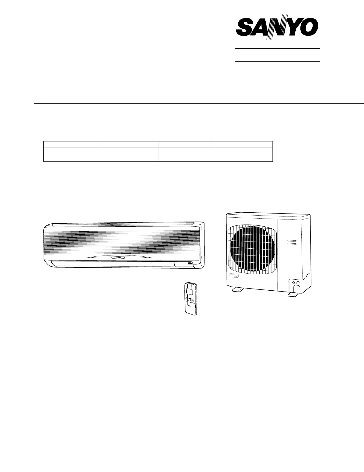
KS2462R / C2462R, CL2462R
SPLIT SYSTEM AIR CONDITIONER
INDOOR MODEL No. PRODUCT CODE No. OUTDOOR MODEL No. PRODUCT CODE No.
KS2462R 854 019 00
Indoor Unit Outdoor Unit
C2462R 854 019 01
CL2462R 854 019 02
FILE NO.
854648419200
KS2462R C2462R
CL2462R
REFERENCE NO. SM830092
– 1 –
SM830092
Page 2
Important
Please Read Before Starting
This air conditioning system meets strict safety and operating
standards. As the installer or service person, it is an important
part of your job to install or service the system so it operates
safely and efficiently.
For safe installation and trouble-free operation, you must :
Carefully read this instruction booklet before beginning.
Follow each installation or repair step exactly as shown.
Observe all local, state, and national electrical codes.
Pay close attention to all warning and caution notices
given in this manual.
This symbol refers to a hazard or
unsafe practice which can result in
severe personal injury or death.
This symbol refers to a hazard or
CAUTION
unsafe practice which can result in
personal injury or product or
property damage.
If Necessary, Get Help
These instructions are all you need for most installation sites
and maintenance conditions. If you require help for a special
problem, contact our sales/service outlet or your certified dealer
for additional instructions.
In Case of Improper Installation
The manufacturer shall in no way be responsible for improper
installation or maintenance service, including failure to follow
the instructions in this document.
SPECIAL PRECAUTIONS
When Wiring
……………………………………………………………………
ELECTRICAL SHOCK CAN CAUSE SEVERE
PERSONAL INJURY OR DEATH. ONLY A
QUALIFIED, EXPERIENCED ELECTRICIAN
SHOULD ATTEMPT TO WIRE THIS SYSTEM.
• Do not supply power to the unit until all wiring and tubing are
completed or reconnected and checked.
• Highly dangerous electrical voltages are used in this system.
Carefully refer to the wiring diagram and these instructions
when wiring. Improper connections and inadequate grounding can cause accidental injury or death.
• Ground the unit following local electrical codes.
• Connect all wiring tightly. Loose wiring may cause overheating at connection points and a possible fire hazard.
When Transporting
……………………………………………………………………
Be careful when picking up and moving the indoor and outdoor
units. Get a partner to help, and bend your knees when lifting to
reduce strain on your back. Sharp edges or thin aluminum fins
on the air conditioner can cut your fingers.
When Installing
……………………………………………………………………
…In a Room
Properly insulate any tubing run inside a room to prevent
“sweating” that can cause dripping and water damage to walls
and floors.
…In Moist or Uneven Locations
Use a raised concrete pad or concrete blocks to provide a
solid, level foundation for the outdoor unit. This prevents water
damage and abnormal vibration.
…In an area with High Winds
Securely anchor the outdoor unit down with bolts and a metal
frame. Provide a suitable air baffle.
…In a Snowy Area (for Heat Pump-type Sys-tems)
Install the outdoor unit on a raised platform that is higher than
drifting snow. Provide snow vents.
When Connecting Refrigerant Tubing
……………………………………………………………………
• Ventilate the room well, in the event that refrigerant gas
leaks during the installation. Be careful not to allow contact
of the refrigerant gas with a flame as this will cause the
generation of poisonous gas.
• Keep all tubing runs as short as possible.
• Use the flare method for connecting tubing.
• Apply refrigerant lubricant to the matching surfaces of the
flare and union tubes before connecting them, then tighten
the nut with a torque wrench for a leak-free connection.
• Check carefully for leaks before starting the test run.
NOTE
Depending on the system type, liquid and gas lines may be
either narrow or wide. Therefore, to avoid confusion the
refrigerant tubing for your particular model is specified as either
“narrow” or “wide” rather than as “liquid” or “gas”.
When Servicing
……………………………………………………………………
• Turn the power OFF at the main power box (mains) before
opening the unit to check or repair electrical parts and
wiring.
• Keep your fingers and clothing away from any moving parts.
• Clean up the site when installation is finished. Check that no
metal scraps or bits of wiring have been left inside the unit.
CAUTION
• Ventilate any enclosed areas when installing or testing the
refrigeration system. Contact of refrigerant gas with fire or
heat can produce poisonous gas.
• Confirm after installation that no refrigerant gas is leaking. If
the gas comes in contact with a burning stove, gas water
heater, electric room heater or other heat source, it can
cause the generation of poisonous gas.
– 2 –
SM830092
Page 3

Table of Contents
1. OPERATING RANGE ....................................................................................... 4
2. SPECIFICATIONS............................................................................................ 5
(1) Unit Specifications ...................................................................................... 5
(2) Major Component Specifications ................................................................ 7
(A) Indoor Unit ............................................................................................ 7
(B) Outdoor Unit.......................................................................................... 8
(3) Other Component Specifications .............................................................. 10
(A) Indoor Unit .......................................................................................... 10
(B) Outdoor Unit........................................................................................ 12
3. DIMENSIONAL DATA..................................................................................... 13
(1) Indoor Unit ................................................................................................ 13
(2) Outdoor Unit.............................................................................................. 14
4. COOLING CAPACITY..................................................................................... 15
5. PERFORMANCE CHARTS ............................................................................ 17
(1) Operating Current ..................................................................................... 17
(2) High and Low Pressure............................................................................. 19
6. AIR THROW DISTANCE CHART................................................................... 21
7. REFRIGERANT FLOW DIAGRAM ................................................................. 22
8. INSTALLATION INSTRUCTIONS .................................................................. 23
9. ELECTRICAL DATA ....................................................................................... 29
10. ELECTRICAL WIRING DIAGRAMS ............................................................... 30
(1) Indoor Unit ................................................................................................ 30
(2) Outdoor Unit.............................................................................................. 31
11. PROCESSES AND FUNCTIONS.................................................................. 35
(1) Room Temperature Control ...................................................................... 35
(2) Dry Operation............................................................................................ 36
(3) Freeze Prevention..................................................................................... 37
(4) Outdoor Fan Speed Control......................................................................38
12. SERVICE PROCEDURES.............................................................................. 39
(1) Troubleshooting ........................................................................................ 39
(2) A Sensor is Defective................................................................................ 50
(3) Checking the Electrical Components ........................................................ 51
– 3 –
SM830092
Page 4
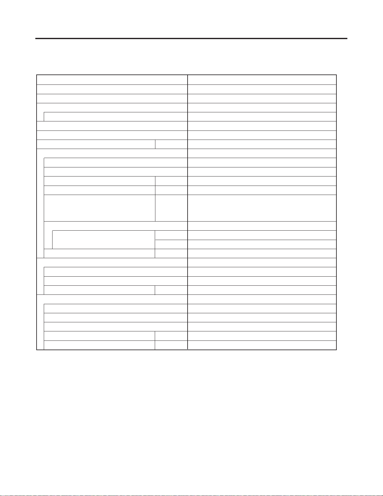
1. OPERATING RANGE
KS2462R / C2462R
Temperature Indoor Air Intake Temp. Outdoor Air Intake Temp.
Maximum 95 °F DB / 71 °F WB 115 °F DB
Minimum 67 °F DB / 57 °F WB 67 °F DB
KS2462R / CL2462R
Temperature Indoor Air Intake Temp. Outdoor Air Intake Temp.
Maximum 95 °F DB / 71 °F WB 115 °F DB
Minimum 67 °F DB / 57 °F WB 0 °F DB
– 4 –
SM830092
Page 5
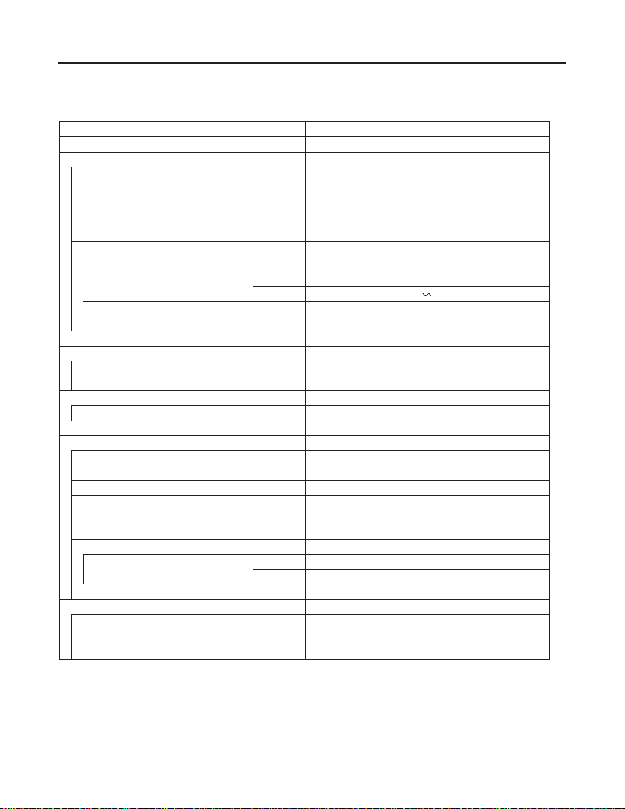
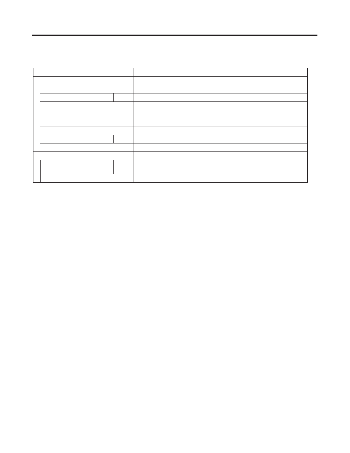
2. SPECIFICATIONS
1-1 Unit Specifications
MODEL No. Indoor Unit
Outdoor Unit C2462R
POWER SOURCE 230 - 208 V / 1 Phase / 60 Hz
PERFORMANCE Cooling
Capacity
Air circulation (Hi)
Moisture removal (High) Pints / h 6.5
ELECTRICAL RATINGS
Voltage rating VAC
Available voltage range 187 – 253
Running amperes* A 10.2
Max. running amperes** A 12.5
Power input W 2,240
Power factor % 95.5
S.E.E.R 13.0
Max. starting amperes A 61
FEATURES
Controls Microprocessor
Timer ON/OFF 24-hours & Program
Fan speed Indoor / Outdoor 3 and Automatic control / 2 (Auto)
Air deflection Horizontal / Vertical – / Automatic
Air filter Washable, easy access
Remote controller (Accessory) RCS - 1PS4U - G
Refrigerant control Capillary tube
Refrigerant tubing connections Flare type
Compressor Scroll
Operation sound
REFRIGERANT TUBING
Limit of tubing length ft. (m)
Limit of tubing length at shipment 23 ( 7 )
Limit of elevation difference
between the two units
Refrigerant tube Narrow tube 3 / 8 (9.52)
outer diameter Wide tube 3 / 4 (19.05)
Refrigerant amount at shipment lbs. (kg) R410A - 6.6 (3)
DIMENSIONS & WEIGHT Indoor unit Outdoor unit
Unit dimensions Height in. (mm)
Package dimensions Height
Net weight lbs. (kg)
Shipping weight
Shipping volume
Cooling:
Rating conditions (*) : Indoor air temperature 80 °F DB / 67 °F WB, Outdoor air temperature 95 °F DB / 75°F WB
Full load conditions (**):Indoor air temperature 80 °F DB / 67 °F WB, Outdoor air temperature 115°F DB
Indoor - Hi/Me/Lo
Outdoor - Hi
Width
Depth
Width
Depth 15-31/32 (406)
BTU / h
kW
Cu.ft. / min.
VAC
BTU / Wh
dB - A 48 / 42 / 38
dB - A 55
ft. (m)
ft. (m)
in. (mm)
in. (mm)
in. (mm)
in. (mm)
in. (mm)
in. (mm)
in. (mm)
lbs. (kg)
cu. ft.(m )
3
27,000
7.912
559
230
13 (330)
44-7/8 (1,140)
8-31/32 (228)
12-25/32 (325)
48-15/32 (406)
40 (18)
44 (20)
5.7 (0.162)
DATA SUBJECT TO CHANGE WITHOUT NOTICE.
KS2462R
26,000
7.619
519
6.4
208
10.9
13.5
2,200
97.0
13.0
61
132 ( 40 )
50 ( 15 )
36-5/8 (930)
37 (940)
13-3/8 (340)
39-3/4 (1,010)
39-3/8 (1,000)
15-3/4 (400)
150 (68)
190 (86.5)
14.1 (0.40)
– 5 –
SM830092
Page 6

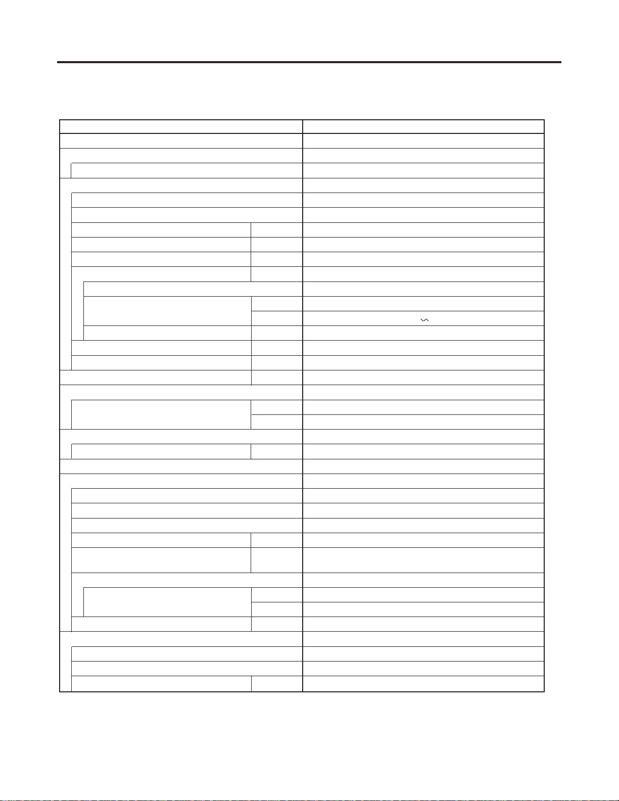
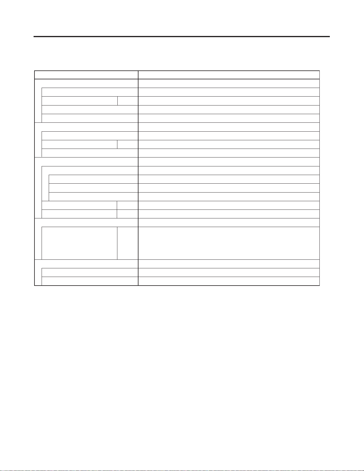
2. SPECIFICATIONS
1-1 Unit Specifications
MODEL No. Indoor Unit
Outdoor Unit CL2462R
POWER SOURCE 230 - 208 V / 1 Phase / 60 Hz
PERFORMANCE Cooling
Capacity
Air circulation (Hi)
Moisture removal (High) Pints / h 6.5
ELECTRICAL RATINGS
Voltage rating VAC
Available voltage range 187 – 253
Running amperes* A 10.2
Max. running amperes** A 12.5
Power input W 2,240
Power factor % 95.5
S.E.E.R 13.0
Max. starting amperes A 61
FEATURES
Controls Microprocessor
Timer 1-hour OFF, ON/OFF 12-hours & Program
Fan speed Indoor / Outdoor 3 and Automatic control / 3 (Auto)
Air deflection Horizontal / Vertical – / Automatic
Air filter Washable, easy access
Remote controller (Accessory) RCS - 1PS4U - G
Refrigerant control Capillary tube
Refrigerant tubing connections Flare type
Compressor Scroll
Operation sound
REFRIGERANT TUBING
Limit of tubing length ft. (m)
Limit of tubing length at shipment 23 ( 7 )
Limit of elevation difference
between the two units
Refrigerant tube Narrow tube 3 / 8 (9.52)
outer diameter Wide tube 3 / 4 (19.05)
Refrigerant amount at shipment lbs. (kg) R410A - 6.6 (3)
DIMENSIONS & WEIGHT Indoor unit Outdoor unit
Unit dimensions Height in. (mm)
Package dimensions Height
Net weight lbs. (kg)
Shipping weight
Shipping volume
Cooling:
Rating conditions (*) : Indoor air temperature 80 °F DB / 67 °F WB, Outdoor air temperature 95 °F DB / 75°F WB
Full load conditions (**):Indoor air temperature 80 °F DB / 67 °F WB, Outdoor air temperature 115°F DB
Indoor - Hi/Me/Lo
Outdoor - Hi
Width
Depth
Width
Depth
BTU / h
kW
Cu.ft. / min.
VAC
BTU / Wh
dB - A 48 / 42 / 38
dB - A 55
ft. (m)
ft. (m)
in. (mm)
in. (mm)
in. (mm)
in. (mm)
in. (mm)
in. (mm)
in. (mm)
lbs. (kg)
cu. ft.(m )
3
27,000
7.912
559
230
13 (330)
44-7/8 (1,140)
8-31/32 (228)
12-25/32 (325)
48-15/32 (406)
15-31/32 (406)
40 (18)
44 (20)
5.7 (0.162)
DATA SUBJECT TO CHANGE WITHOUT NOTICE.
KS2462R
26,000
7.619
519
6.4
208
10.9
13.5
2,200
97.0
13.0
61
132 ( 40 )
50 ( 15 )
36-5/8 (930)
37 (940)
13-3/8 (340)
39-3/4 (1,010)
39-3/8 (1,000)
15-3/4 (400)
150 (68)
190 (86.5)
14.1 (0.40)
– 6 –
SM830092
Page 7
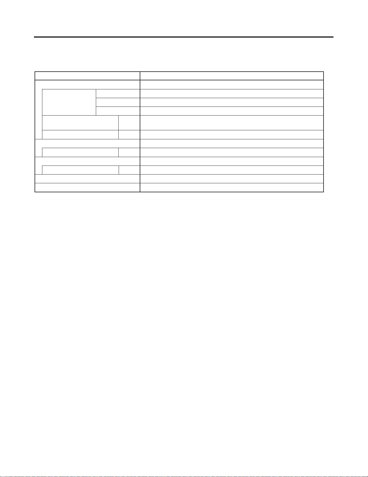
2. SPECIFICATIONS
(2) Major Component Specifications
(A) Indoor Unit
MODEL No. KS2462R
Source 230 - 208 V / 1 phase / 60 Hz
Remote controller (Accessory) RCS - 1PS4U - G
Controller P. C. B Ass'y CR - KS2462R
Control circuit fuse 250 V, 3 A
Fan
Type Cross-flow
Number ... Dia. and length in. (mm) 1 ... O.D. 4 (100), L33-3/8 (847)
Fan motor
Model KFG4X - 31B6P-S
Source 230 - 208 V / 1 phase / 60 Hz
No. of pole … r.p.m. (230 V, High) rpm 4 … 1,365
Nominal output W 30
Coil resistance Ω BRW - WHT : 161.2 , ORG - YEL : 26.9
(Ambient temperature 68 °F) WHT - VLT : 11.6 , YEL - BLK : 22.8
VLT - ORG : 68.7 , BLK - PNK : 115.2
Safety device Internal
Operating temperature Open °F 266 ± 9
Close °F 181 ± 27
Run capacitor VAC, µF 440 V , 1.5 µF
Heat exchanger
Coil Aluminum plate fin / Copper tube
Rows … Fins per inch 2 … 19.5
Face area ft.
Flap Motor
Type Stepping motor
Model ... Q’ty MP24GA2 ... 2
Step angle 5.625 deg / step
Rating V DC 12 V
Coil resistance (Ambient temperature 77 °F) Ω 400 ± 7 %
2
(m2) 2.30 (0.214)
DATA SUBJECT TO CHANGE WITHOUT NOTICE
– 7 –
SM830092
Page 8
2. SPECIFICATIONS
(2) Major Component Specifications
(B) Outdoor Unit
MODEL No. C2462R
Source 230 - 208 V / 1 phase / 60 Hz
Compressor Scroll (Hermetic)
Model ZP23K3E
Source 230 - 208 V / 1 phase / 60 Hz
Nominal output W 2,400
Compressor oil cc 1,120
Coil resistance (Ambient temperature 77 °F) Ω C - R : 2.28 , C - S : 1.01
Safety device Internal type
Overload relay models —
Operating temperature Open °F 284 ± 9
Close °F
Operating ampere (at 77 °F) A —
Run capacitor VAC, µF 400 V, 40 µF
Refrigerant amount charged at shipment lbs. (kg) R410A : 6.6 (3)
High pressure switch ACB - 1UB24W
Set pressure OFF MPa 4.15
ON MPa 3.15 ± 0.3
Fan Propeller
Number...diameter in. (mm) 1 … 18-3/32 (460)
Fan speeds 2 (AUTO)
Fan motor
Model KFC6T - 91D6P
Source 230 - 208 V / 1 phase / 60 Hz
No. of pole … rpm (230 V, High) rpm 6 … 879
Nominal output W 110
Coil resistance Ω BRW – WHT : 67.14 , VLT – YEL : 11.42
(Ambient temperature 68 °F)
Safety device
Operating temperature Open °F 248 ± 9
Close °F 171 ± 27
Run capacitor VAC, µF 440 V, 4 µF
Heat exchanger
Coil Aluminum plate fin / Copper tube
Rows … Fins per inch 2 … 14.1
Face area ft.
2
(m2) 8.72 (0.81)
WHT – VLT : 64.85 , YEL – PNK : 10.60
DATA SUBJECT TO CHANGE WITHOUT NOTICE
156 189
+ 0
– 0.15
Internal
– 8 –
SM830092
Page 9
2. SPECIFICATIONS
(2) Major Component Specifications
(B) Outdoor Unit
MODEL No. CL2462R
Source 230 - 208 V / 1 phase / 60 Hz
Controller P.C.B. Ass'y CR - CL2432 (Microprocessor)
Control circuit fuse 250 V, 3 A
Compressor Scroll (Hermetic)
Model ZP23K3E
Source 230 - 208 V / 1 phase / 60 Hz
Nominal output W 2,400
Compressor oil cc 1,120
Coil resistance (Ambient temperature 77 °F) Ω C – R : 0.885 , C – S : 1.773
Safety device Internal type
Overload relay models —
Operating temperature Open °F 284 ± 9
Close °F 156 189
Operating ampere (at 77 °F) A —
Run capacitor VAC, µF 400 V, 40 µF
Crank case heater V, W 230 V, 30 W
Refrigerant amount charged at shipment lbs. (kg) R410A : 6.6 (3)
High pressure switch ACB-1UB24W
Set pressure OFF MPa 4.15
ON MPa 3.15 ± 0.3
Fan Propeller
Number...diameter in. (mm) 1 ... 18 - 3/32 (460)
Fan speeds 3 (AUTO)
Fan motor
Model KFC6T - 91D6P
Source 230 - 208 V / 1 phase / 60 Hz
No. of pole ..... rpm (230 V, High) 6 ... 879
Nominal output W 110
Coil resistance Ω BRN – WHT : 67.14 , VLT – YEL : 11.42
(Ambient temperature 68 °F) WHT – VLT : 64.85 , YEL – PNK : 10.60
Safety device Internal
Operating temperature Open °F 248 ± 9
Close °F 171 ± 27
Run capacitor VAC, µF 440 V, 4 µF
Heat exchange
Coil Aluminum plate fin / Copper tube
Rows ..... Fins per inch 2 ... 14.1
2
Face area ft.
(m2) 8.72 (0.81)
DATA SUBJECT TO CHANGE WITHOUT NOTICE
+ 0
– 0.15
– 9 –
SM830092
Page 10
2. SPECIFICATIONS
(3) Other Component Specifications
(A) Indoor Unit
MODEL No. KS2462R
Power Transformer ATR – T5
Rated Primary AC 230 V, 60 Hz
Secondary AC19 V, 0.5 A
Capacity 9.5 VA
Coil resistance
(Ambient temprature 77 °F) Secondary (BRN - BRN) : 3.9
Thermistor cut off temperature 277 °F
Thermistor (Coil sensor) DTN - TKS131B
Coil resistance kΩ 32 °F : 15.0 ± 2 %
Thermistor (Room sensor) DTN - TKS128B
Coil resistance kΩ 77 °F : 5.0 ± 3 %
Lamp Ass'y IND - K301AH
Flap Motor MP24GA2
Ω
Primary (WHT - WHT) : 457.5
– 10 –
SM830092
Page 11
2. SPECIFICATIONS
(3) Other Component Specifications
(A) Outdoor Unit
MODEL No. C2462R
Compressor Motor Magnetic Contactor FC - 1SUL
Coil rated AC 240 V, 60 Hz
Coil resistance (at 68 °F) Ω 587 ± 5 %
Contact rated (Main) AC 240 V, 26 A
Contact rated (Auxiliary) AC 240 V, 3 A
Power Relay HH62S
Coil rated AC 240 V, 60 Hz
Coil resistance (at 68 °F) kΩ 17.2
Contact rated AC 220 V, 5 A
Thermostat (Coil sensor) YTB - 4U305F
Operating Temperature °F 79 ± 3 OFF
75 ON
Contact rated 200 to 240 V, 1 A
+ 3
– 1
– 11 –
SM830092
Page 12
2. SPECIFICATIONS
(3) Other Component Specifications
(B) Outdoor Unit
MODEL No. CL2462R
Compressor Motor Magnetic Contactor FC - 1SUL
Coil rated AC 240 V, 60 Hz
Coil resistance (at 77 °F) Ω 587 ± 5 %
Contact rated (Main) AC 240 V, 26 A
Contact rated (Auxiliary) AC 240 V, 3 A
Power Relay HH62S
Coil rated AC 240 V, 60 Hz
Coil resistance (at 77 °F) kΩ 17.2
Contact rated AC 220 V, 5 A
Power Transformer ATR - I35B
Rated
Primary AC 220 V, 60 Hz
Secondary 14 V, 0.2 A
Capacity 2.8 VAC
Coil resistance (at 78 °F ) Ω WHT – WHT : 482.5 , BRN – BRN : 3.95
Thermal cut off temperature °F 266
Thermistor (Outdoor Temp. sensor)
Coil resistance kΩ 14 °F : 23.7 , 50 °F : 9.7
23 °F : 18.8 , 68 °F : 6.5
32 °F : 15.0 , 86 °F : 4.4
41 °F : 12.1 , 104 °F : 3.1
Solenoid control valve or coil
Solenoid control valve VPV - 202DQ50
Solenoid coil VPV - MOAQ517B1
PBC - 41E - S4
113 °F : 2.6
– 12 –
SM830092
Page 13
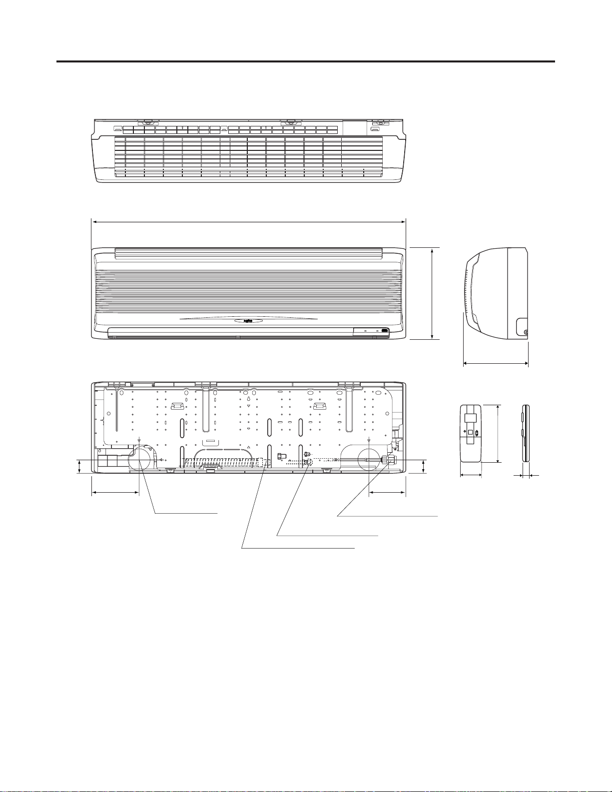
3. DIMENSIONAL DATA
(1) Indoor Unit: KS2462R
44-7/8
13
1-7/8
6-27/32
Center of tubing
hole (2 places)
Narrow tube 3/8"(ø9.52)
Drain hose O.D. 23/32"(ø18)
5-5/16
Wide tube 3/4"(ø19.05)
8-31/32
Remote control unit
6-7/32
1-7/8
2-13/32
Dimension : inch
25/32
2199_M_S
– 13 –
SM830092
Page 14
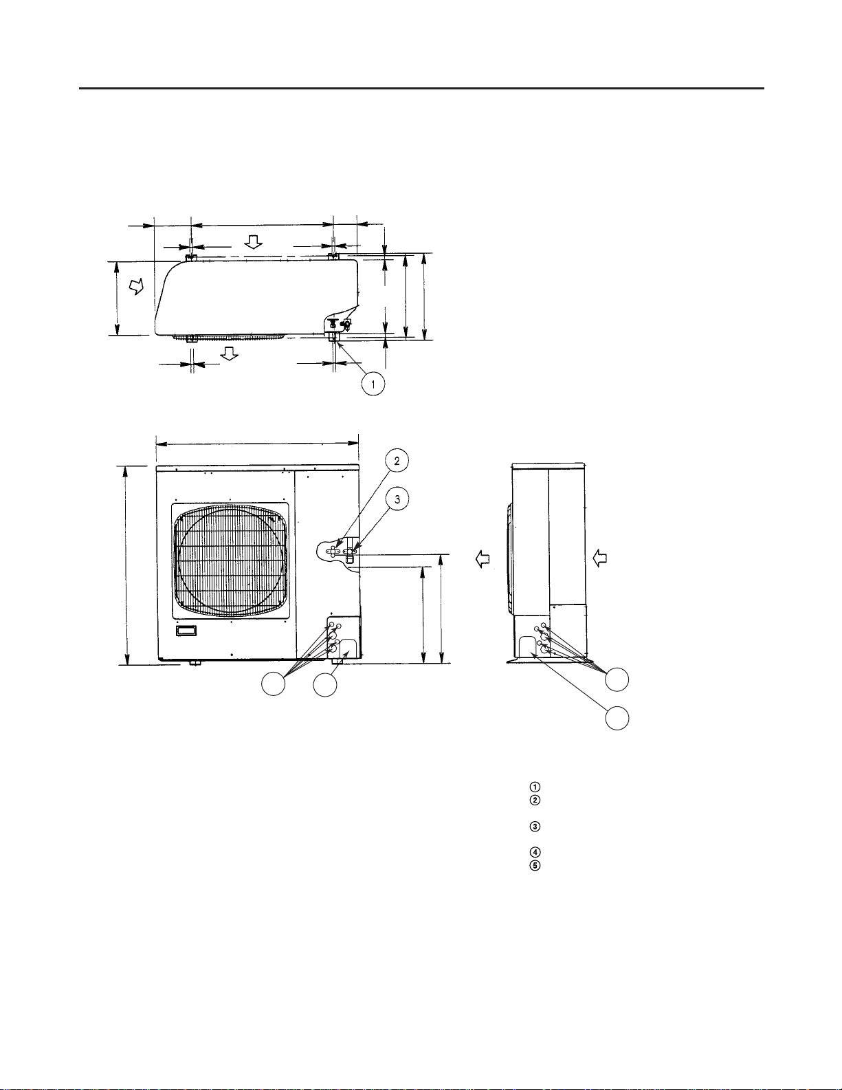
3. DIMENSIONAL DATA
(2) Outdoor Unit: C2462R, CL2462R
13-3/8
36-5/8
6-23/32
1/2
25-31/32
37
1/21/2
1/2
4-3/8
25/323/4
15-15/16
14-31/32
18-1/16
16-7/8
5
4
Dimension : inch
Hole for anchor bolt (4-R1/4)
Refrigerant tube joint (narrow tube)
Flare connection 3/8 in (9.52 mm)
Refrigerant tube joint (wide tube)
Flare connection 3/4 in (19.05 mm)
Refrigerant tubing inlet
Power supply inlet
5
4
– 14 –
SM830092
Page 15
4. COOLING CAPACITY
Indoor Unit: KS2462R Outdoor Unit: C2462R
1
• 230V / 1 phase / 60Hz
RATING CAPACITY : 27,000 BTU / h AIR FLOW RATE : 559 Cu.ft / min
EVAPORATOR CONDENSER
ENT. TEMP. °F (°C) AMBIENT TEMP. °F (°C)
WB DB 75 85 95 105 115
TC
CI 1.66
72(22.2) SHC 18,460
59
(15.0)
63
(17.2)
67
(19.4)
71
(21.7)
75
(23.9)
76(24.4) SHC 20,150
80(26.7) SHC 21,930
84(28.9) SHC 23,620
88(31.1)
72(22.2)
76(24.4)
80(26.7)
84(28.9)
88(31.1)
72(22.2)
76(24.4)
80(26.7)
84(28.9)
88(31.1)
72(22.2)
76(24.4)
80(26.7)
84(28.9)
88(31.1)
76(24.4)
80(26.7)
84(28.9)
88(31.1)
SHC 25,320
TC
CI
SHC
SHC
SHC
SHC
SHC
TC
CI
SHC
SHC
SHC
SHC
SHC
TC
CI
SHC
SHC
SHC
SHC
SHC
TC
CI
SHC
SHC
SHC
SHC
(23.9) (29.4) (35.0) (40.6) (46.1)
27,350
28,380
1.67
16,130
17,820
19,590
21,290
22,990
29,460
1.69
13,770
15,470
17,240
18,940
20,630
31,020
1.7
11,500
13,190
14,960
16,660
18,360
31,640
1.74
10,560
12,330
14,020
15,720
26,030
1.81
17,640
19,340
21,110
22,810
24,500
27,110
1.83
15,400
17,100
18,870
20,570
22,260
28,300
1.85
13,170
14,870
16,640
18,330
20,030
29,940
1.87
10,990
12,680
14,450
16,150
17,850
30,620
1.9
10,120
11,900
13,590
15,290
24,520
1.97
16,740
18,430
20,210
21,900
23,600
25,760
2
14,660
16,360
18,130
19,820
21,520
# 27,000
2.02
12,510
14,210
15,980
17,680
19,370
28,780
2.05
10,450
12,140
13,920
15,610
17,310
29,540
2.08
9,680
11,450
13,150
14,840
22,820
2.23
15,760
17,450
19,220
20,920
22,620
24,220
2.26
13,840
15,530
17,310
19,000
20,700
25,570
2.29
11,810
13,510
15,280
16,970
18,670
27,510
2.32
9,870
11,570
13,340
15,040
16,730
28,300
2.35
9,170
10,950
12,640
14,340
20,930
2.49
14,710
16,400
18,170
19,870
20,930
22,550
2.52
12,970
14,670
16,440
18,140
19,830
24,000
2.55
11,060
12,760
14,530
16,230
17,920
26,110
2.59
9,260
10,950
12,730
14,420
16,120
26,970
2.63
8,650
10,420
12,110
13,810
TC : Total Cooling Capacity (BTU / h)
SHC : Sensible Heat Capacity (BTU / h)
CI : Compressor Input (kW)
Rating conditions are
: Outdoor Ambient Temp. 95 °F DB
: Indoor Unit Entering Air Temp. 80 °F DB / 67 °F WB
SM830092
– 15 –
Page 16
4. COOLING CAPACITY
Indoor Unit: KS2462R Outdoor Unit: C2462R
1
• 208V / 1 phase / 60Hz
RATING CAPACITY : 26,000 BTU / h AIR FLOW RATE : 519 Cu.ft / min
EVAPORATOR CONDENSER
ENT. TEMP. °F (°C) AMBIENT TEMP. °F (°C)
WB DB 75 85 95 105 115
TC
CI 1.64
72(22.2) SHC 17,760
59
(15.0)
63
(17.2)
67
(19.4)
71
(21.7)
75
(23.9)
76(24.4) SHC 19,360
80(26.7) SHC 21,030
84(28.9) SHC 22,630
88(31.1)
72(22.2)
76(24.4)
80(26.7)
84(28.9)
88(31.1)
72(22.2)
76(24.4)
80(26.7)
84(28.9)
88(31.1)
72(22.2)
76(24.4)
80(26.7)
84(28.9)
88(31.1)
76(24.4)
80(26.7)
84(28.9)
88(31.1)
SHC 24,230
TC
CI
SHC
SHC
SHC
SHC
SHC
TC
CI
SHC
SHC
SHC
SHC
SHC
TC
CI
SHC
SHC
SHC
SHC
SHC
TC
CI
SHC
SHC
SHC
SHC
(23.9) (29.4) (35.0) (40.6) (46.1)
26,340
27,330
1.66
15,540
17,140
18,810
20,410
22,010
28,370
1.67
13,310
14,910
16,580
18,180
19,770
29,870
1.69
11,150
12,750
14,420
16,020
17,620
30,470
1.72
10,240
11,910
13,510
15,110
25,060
1.79
16,960
18,560
20,230
21,830
23,430
26,100
1.82
14,840
16,430
18,110
19,700
21,300
27,250
1.83
12,720
14,320
15,990
17,590
19,190
28,830
1.85
10,650
12,250
13,920
15,520
17,120
29,480
1.88
9,810
11,480
13,080
14,680
23,610
1.95
16,080
17,680
19,350
20,950
22,550
24,800
1.98
14,110
15,710
17,380
18,980
20,580
# 26,000
2
12,080
13,680
15,350
16,950
18,550
27,720
2.03
10,130
11,730
13,400
15,000
16,600
28,440
2.06
9,380
11,050
12,650
14,250
21,970
2.23
15,120
16,720
18,390
19,990
21,590
23,320
2.27
13,310
14,910
16,580
18,180
19,780
24,620
2.29
11,390
12,990
14,660
16,260
17,860
26,490
2.32
9,570
11,170
12,840
14,440
16,040
27,250
2.36
8,890
10,560
12,160
13,760
20,150
2.52
14,100
15,700
17,370
18,970
20,150
21,710
2.55
12,470
14,070
15,740
17,340
18,940
23,110
2.58
10,670
12,260
13,940
15,540
17,130
25,140
2.62
8,970
10,570
12,240
13,840
15,440
25,970
2.66
8,380
10,050
11,650
13,250
TC : Total Cooling Capacity (BTU / h)
SHC : Sensible Heat Capacity (BTU / h)
CI : Compressor Input (kW)
Rating conditions are
: Outdoor Ambient Temp. 95 °F DB
: Indoor Unit Entering Air Temp. 80 °F DB / 67 °F WB
SM830092
– 16 –
Page 17
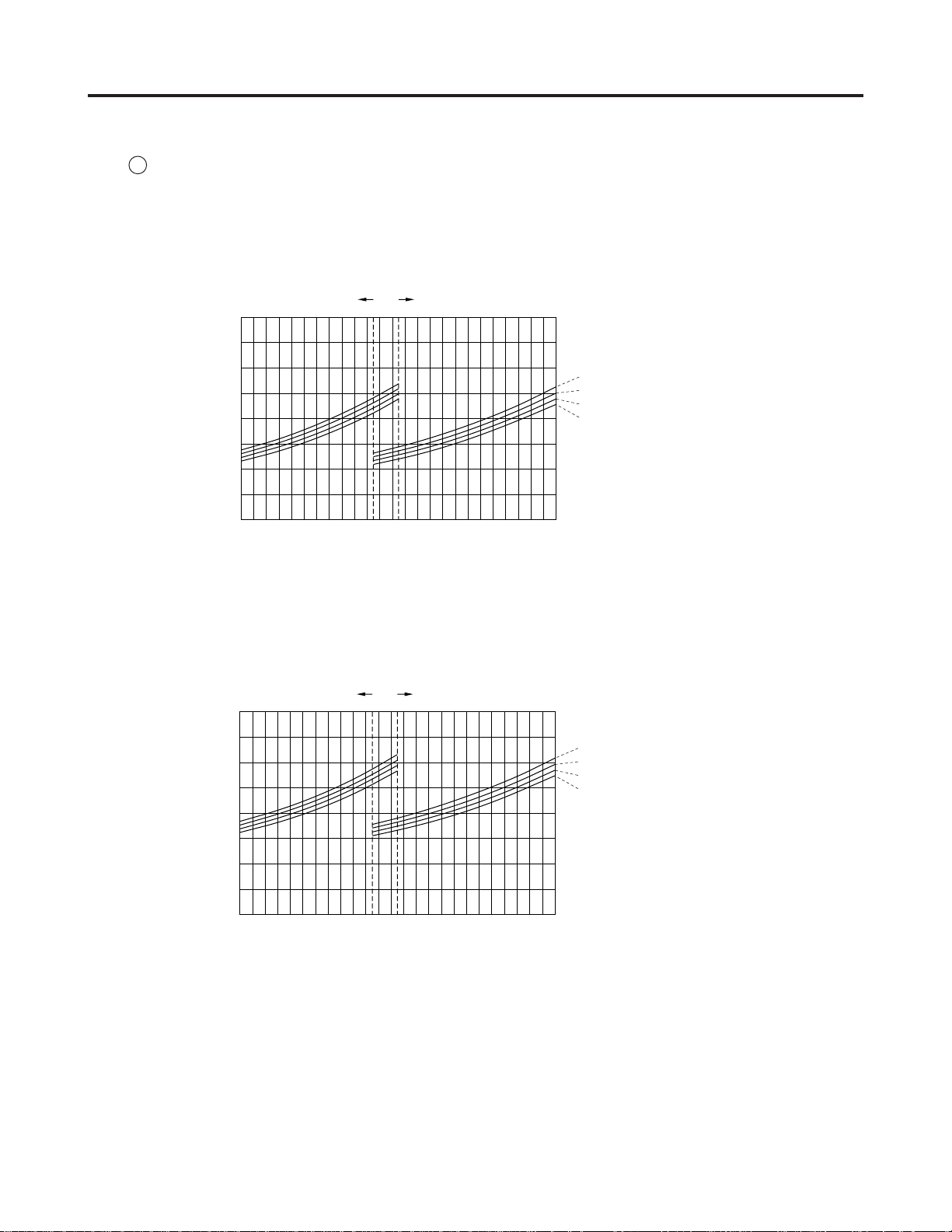
5. PERFORMANCE CHARTS
(1) Operating Current
Indoor Unit: KS2462R Outdoor Unit: C2462R
1
Operating current characteristics versus outdoor ambient temperature and indoor temperature.
(Indoor relative humidity: 50%, Indoor fan speed: High)
230V
208V
Outdoor fan speed
Low
14
13
12
11
10
9
8
Operating current (A)
7
59 68 77 86 95 104
(15) (20) (25) (30) (35) (40)
Outdoor ambient temp. °F (°C)
Outdoor fan speed
Low
14
13
12
11
10
9
8
Operating current (A)
7
High
High
Indoor
temp.
°F (°C)
85 (30)
80 (27)
75 (24)
70 (21)
1061_X_S
Indoor
temp.
°F (°C)
85 (30)
80 (27)
75 (24)
70 (21)
59 68 77 86 95 104
(15) (20) (25) (30) (35) (40)
Outdoor ambient temp. °F (°C)
– 17 –
1062_X_S
SM830092
Page 18
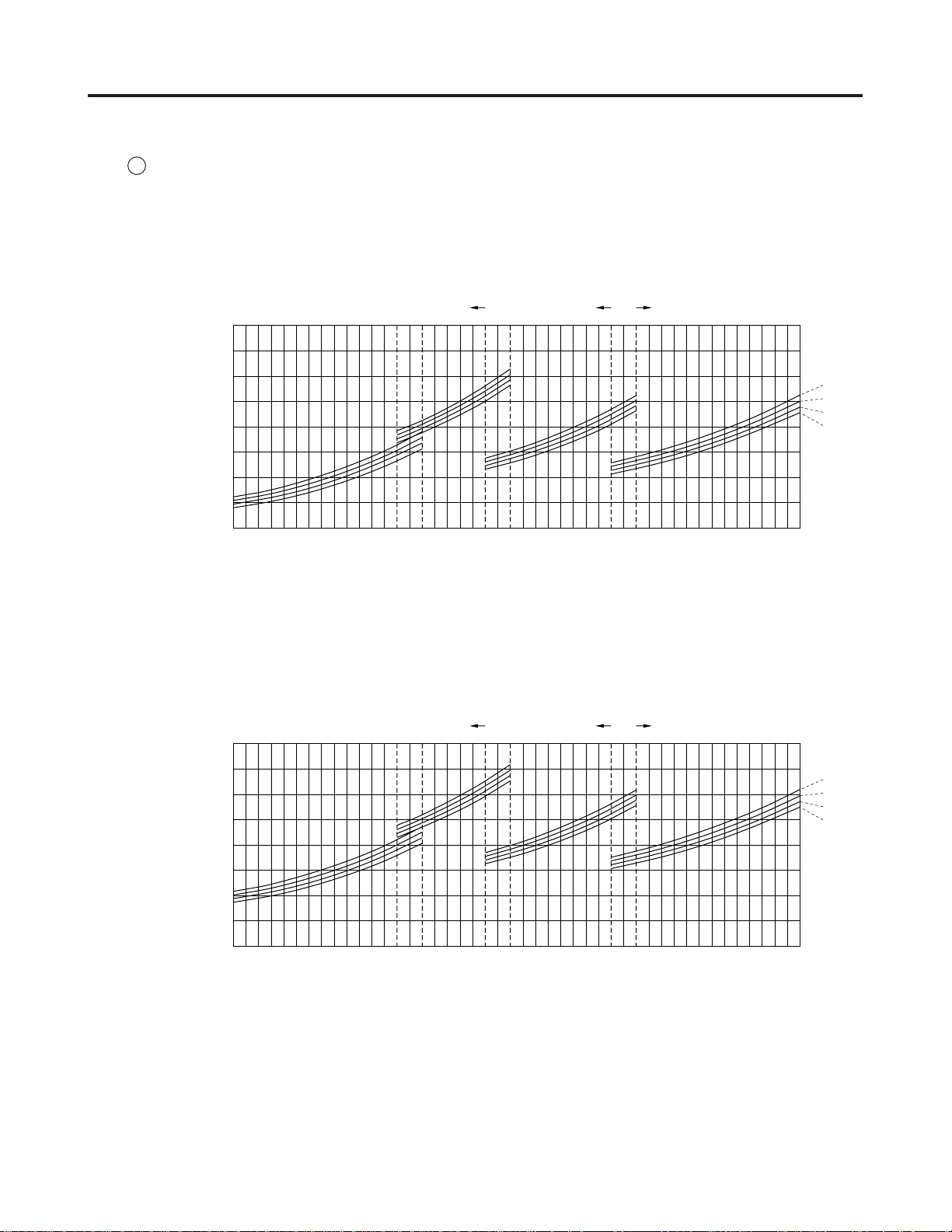
5. PERFORMANCE CHARTS
(1) Operating Current
Indoor Unit: KS2462R Outdoor Unit: CL2462R
2
Operating current characteristics versus outdoor ambient temperature and indoor temperature.
(Indoor relative humidity: 50%, Indoor fan speed: High)
230V
Operating current (A)
208V
Operating current (A)
Outdoor fan speed
Low High
14
13
12
11
10
9
8
7
23 32 41 50
(–5) (0) (5) (10) (35) (40)
14
13
12
11
10
9
8
7
59 68 77 86 95 104
(15) (20) (25) (30)
Outdoor ambient temp. °F (°C)
Outdoor fan speed
Low High
Med
Med
Indoor
temp.
°F (°C)
85 (30)
80 (27)
75 (24)
70 (21)
1063_X_S
Indoor
temp.
°F (°C)
85 (30)
80 (27)
75 (24)
70 (21)
23 32 41 50
(–5) (0) (5) (10) (35) (40)
59 68 77 86 95 104
(15) (20) (25) (30)
Outdoor ambient temp. °F (°C)
– 18 –
1064_X_S
SM830092
Page 19

5. PERFORMANCE CHARTS
(2) High and Low Pressure
Indoor Unit: KS2462R Outdoor Unit: C2462R
1
• High Pressure
High pressure characteristics versus outdoor ambient temperature and indoor temperature.
(Indoor relative humidity: 50%, Indoor fan speed: High)
230V / 208 V
480
460
440
420
400
380
360
340
Discharge pressure (psig)
320
300
59 68 77 86 95 104
(15) (20) (25) (30) (35) (40)
• Low Pressure
Outdoor fan speed
Low
Outdoor ambient temp. °F (°C)
High
Indoor
temp.
°F (°C)
85 (30)
80 (27)
75 (24)
70 (21)
1065_X_S
Low pressure characteristics versus outdoor ambient temperature and indoor temperature.
(Indoor relative humidity: 50%, Indoor fan speed: High)
230V / 208 V
170
160
150
140
130
120
Suction pressure (psig)
110
59 68 77 86 95 104
(15) (20) (25) (30) (35) (40)
Outdoor fan speed
Low
Outdoor ambient temp. °F (°C)
High
– 19 –
Indoor
temp.
°F (°C)
85 (30)
80 (27)
75 (24)
70 (21)
1066_X_S
SM830092
Page 20

5. PERFORMANCE CHARTS
(2) High and Low Pressure
Indoor Unit: KS2462R Outdoor Unit: CL2462R
2
• High Pressure
High pressure characteristics versus outdoor ambient temperature and indoor temperature.
(Indoor relative humidity: 50%, Indoor fan speed: High)
230 / 208V
500
480
460
420
400
380
360
340
Discharge pressure (psig)
320
300
23 32 41 50
(–5) (0) (5) (10) (35) (40)
Low High
Outdoor ambient temp. °F (°C)
Outdoor fan speed
Med
59 68 77 86 95 104
(15) (20) (25) (30)
• Low Pressure
Low pressure characteristics versus outdoor ambient temperature and indoor temperature.
(Indoor relative humidity: 50%, Indoor fan speed: High)
Indoor
temp.
°F (°C)
85 (30)
80 (27)
75 (24)
70 (21)
1067_X_S
230 / 208V
170
160
150
140
130
120
Suction pressure (psig)
110
23 32 41 50
(–5) (0) (5) (10) (35) (40)
Outdoor fan speed
Low High
59 68 77 86 95 104
(15) (20) (25) (30)
Outdoor ambient temp. °F (°C)
Med
– 20 –
Indoor
temp.
°F (°C)
85 (30)
80 (27)
75 (24)
70 (21)
1068_X_S
SM830092
Page 21

6. AIR THROW DISTANCE CHART
Indoor Unit: KS2462R
Room air temp. : 80°F (26.7°C)
Fan speed : High
Horizontal distance (ft.)
0
5
10
Axis air velocity (ft./sec.)
Vertical distance (ft.)
15
5 1015202530
: Flap angle 0° , : Axis air velocity 0 °
: Flap angle 30°, : Axis air velocity 30 °
2200_M_S
– 21 –
SM830092
Page 22

7. REFRIGERANT FLOW DIAGRAM
Indoor Unit: KS2462R Outdoor Unit: C2462R
Indoor Unit Outdoor Unit
Wide tube
O. D.
3/4"
(19.05mm)
Evaporator
O. D.
3/4"
(19.05mm)
Wide tube
service valve
Accumulator
High
pressure
switch
LP
Compressor
HP
Narrow tube
O. D.
3/8"
(9.52 mm)
Narrow tube
service valve
O. D.
3/8"
(9.52 mm)
Capillary
tube
Strainer
Indoor Unit: KS2462R Outdoor Unit: CL2462R
Indoor Unit Outdoor Unit
O. D.
3/4"
(19.05mm)
Evaporator
Wide tube
O. D.
3/4"
(19.05mm)
Wide tube
service valve
Accumulator
Capillary
Sub-condenser
High
pressure
switch
HP
S
HGBV
Condenser
2201_M_S
LP
Compressor
Narrow tube
O. D.
3/8"
(9.52 mm)
O. D.
3/8"
(9.52 mm)
Narrow tube
service valve
– 22 –
Capillary
tube
Condenser
Strainer
Sub-condenser
2202_M_S
SM830092
Page 23

8. INSTALLATION INSTRUCTIONS
1) Tubing Length
• Refrigerant tubing between the indoor and
outdoor units should be kept as short as
INDOOR
UNIT
Tubing length (L)
possible.
• Select and decide the installation location
so that the length of the refrigerant tubing
Elevation difference (H)
OUTDOOR
UNIT
will be within the limits given in Table 1.
Fig. 1
Table 3
Model Length at Shipment Length (L) Difference (H) Additional Refrigerant
C2462R, CL2462R 23 132 50 0.43
*
If total tubing length becomes 23 to 132 ft. (max.), additional refrigerant (R410A) charge of 0.43 oz./ft. is required.
No additional charge of compressor oil is necessary.
Max. Allowable Tubing Limit of Tubing Limit of Elevation Required Amount of
(ft.) (ft.) (ft.) (oz./ft.)
0711_M_I
*
– 23 –
SM830092
Page 24

8. INSTALLATION INSTRUCTIONS
2) Selecting the Installation Site
Indoor Unit
AVOID:
areas where leakage of flammable gas may
be expected.
places where large amounts of oil mist
exist. (Fig. 2)
direct sunlight.
locations near heat sources which may
affect performance of the unit.
locations where external air may enter the
room directly. This may cause “sweating”
on the air discharge ports, causing them to
spray or drip. (Fig. 3)
locations where the remote control unit will
be splashed with water or affected by
dampness or humidity.
Indoor unit
Outside drainage
Drain hose
2203_M_S
Fig. 2
DO:
select an appropriate position from which
every corner of the room can be uniformly
air-conditioned.
select a location that will hold weight of the
unit.
select a location where the tubing and drain
pipe have the shortest run to the outside.
(Fig. 2)
allow room for operation and maintenance
as well as unrestricted air flow around the
unit. (Fig. 3a and 3b)
Install the unit within the maximum
elevation difference above or below the
outdoor unit and within a total tubing length
from the outdoor unit as detailed in Table 1
and Fig. 1 on the previous page.
6 inches
min.
INDOOR UNIT
CAUTION
6 inches min.
Front View
Fig. 3a
For stable operation of
the air conditioner, do
not install wall-mounted
type indoor units less
than 5 ft. from floor
level.
Fig. 3b
6 inches
min.
2204_M_S
Indoor Unit
Wall
Minimum height
from floor level
5 ft.
Floor level
2205_M_S
– 24 –
SM830092
Page 25

8. INSTALLATION INSTRUCTIONS
Outdoor Unit
AVOID:
heat sources, exhaust fans, etc. Fig. 4
damp, humid or uneven locations.
DO:
choose a place as cool as possible.
choose a place that is well ventilated and
outside air temperature does not exceed
maximum 115 °F constantly.
allow enough room around unit for air intake/
exhaust and possible maintenance. Fig. 5
provide a solid base; about 6 inch above
grond level to reduce humidity and possible
water damage in the unit and decrease
service life. Fig. 6
use lug bolts or equivalent to bolt down unit,
reducing vibration and noise.
CAUTION
Min.
1 inch
Hot air
4 in.
Air in
Outdoor
unit
Min. 2 ft.
Min.
1 inch
0931_C_I
Exhaust fan
Heat source
Fig. 4
Obstacle above
Air
discharge
Ground
Fig. 5
Air in
0591_C_I
Min.
7 ft.
0932_C_I
If more than 2 outdoor units are installed in the
same location, keep at least 3 meters away from
the neighboring unit to avoid influence of air
discharge.
Air discharge chamber for top discharge
Install the air-discharge chamber in the filed when:
it is difficult to keep a space of minimum 2 ft.
between the air-discharge outlet and the
obstacle.
the air-discharge outlet is facing the sidewalk
and discharged hot air can annoy the
passers-by.
Refer to Fig. 6 and Fig. 7.
– 25 –
Air
discharge
Concrete block
4 inch 1 ft. 4 inch
beams or equal
Anchor bolts
(4 pieces)
Min. 6 inch
0934_C_I
Fig. 6
Air discharge
0426_C_I
Fig. 7
SM830092
Page 26

8. INSTALLATION INSTRUCTIONS
IMPORTANT
Wind shield
(air discharge side)
Front
3 -
ø1-9/16"
hole
6 -
ø15/64" hole
9-27/32"21-5/8"15/16"
5-3/16"
22-7/16"1/2"
23-15/32"
21-13/16"
5-5/32"9-27/32"9-27/32"1-1/16"
21-13/16"
Wind Shield for "CL" Model
It is recommended to use wind shields for "CL" model
(Fig. 5b). "CL" model is designed to use in low outdoor
temperature conditions.
General
When the outdoor unit is installed in a position exposed
to strong wind (like seasonal winds with low air temperature in winter), a suitable wind shield must be installed
on the outdoor unit.
This unit is designed so that the fan of the outdoor unit
runs at low speed when the air conditioner is operated at
low outdoor air temperatures. When the outdoor unit is
exposed to strong wind, the system pressure drops
because of the freeze protector.
Fig. 5b
Recommended outer dimensions of wind shield
(field supply)
For outer dimensions of the wind shield, see Fig. 5c.
CL2462R
Fig. 5c
SM830092
– 26 –
Page 27

8. INSTALLATION INSTRUCTIONS
3) Electrical Wiring
General Precautions on Wiring
(1) Before wiring, confirm the rated voltage of
the unit as shown on its nameplate, then
carry out the wiring closely following the
wiring diagram.
Provide a power outlet to be used
(2)
exclusively for each unit, and a power
supply disconnect and circuit breaker for
overcurrent protection should be
provided in the exclusive line.
(3) T
o prevent possible hazards from
insulation
failure, the unit must be grounded.
(4) Each wiring connection must be done in
accordance with the wiring system
diagram. Wrong wiring may cause the
unit to misoperate or become damaged.
(5) Do not allow wiring to touch the refrigerant
tubing, compressor, or any moving parts
of the fan.
(6) Unauthorized changes in the internal
wiring can be very dangerous. The
manufacturer will accept no repsonsibility
for any damage or misoperation that
occurs as a result of such unauthorized
changes.
(7) Regulations on wire diameters differ from
locality to locality. For field wiring rules,
please refer to your LOCAL ELECTRICAL
CODES before beginning. You must
ensure that installation complies with all
relevant rules and regulations.
– 27 –
SM830092
Page 28

8. INSTALLATION INSTRUCTIONS
7-2. Recommended Wire Length and Wire Diameter for Power Supply System
Time Delay
Fuse or
Circuit
Capacity
Models
*1
Power Supply
(A)
(B)*1 Inter-unit
Wiring
AGW #14
C2462R, CL2462R 64 ft. (AWG #12) 35 A
132 ft.
*1 Refer to the Wiring System Diagrams (See below diagram) for the meaning of “A” and “B.”
AWG = American Wire Gauge
Disconnect SW
1
2
G
4
(Field supply)
Ground
(B)
1
2
G
4
NOTE
To access the electrical component box, open the air
intake grille and remove the electrical component box
cover.
7-3. Wiring System Diagram
Outdoor Unit: “C”, “CL” models
Single-phase
Indoor Unit Outdoor Unit
60 Hz, 208/230 V
L1
L2
(A)
G
Ground
– 28 –
SM830092
Page 29

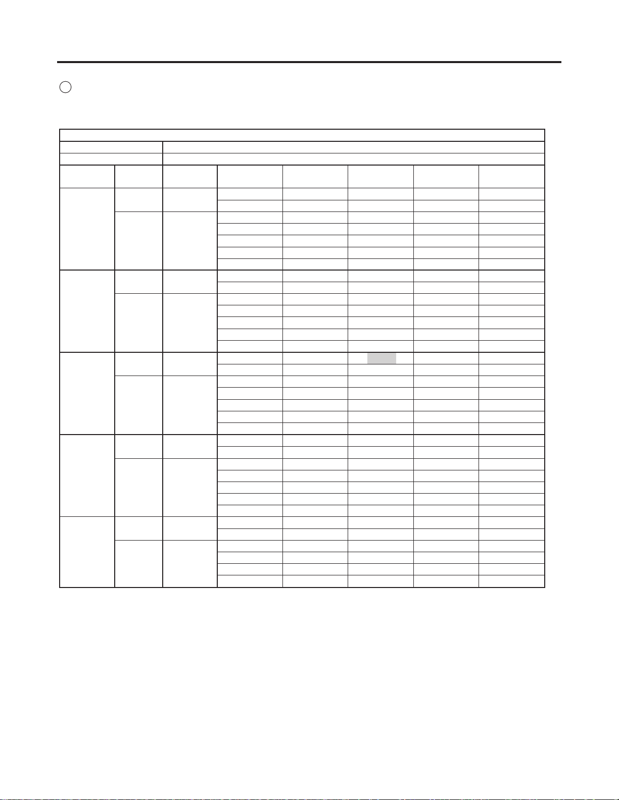
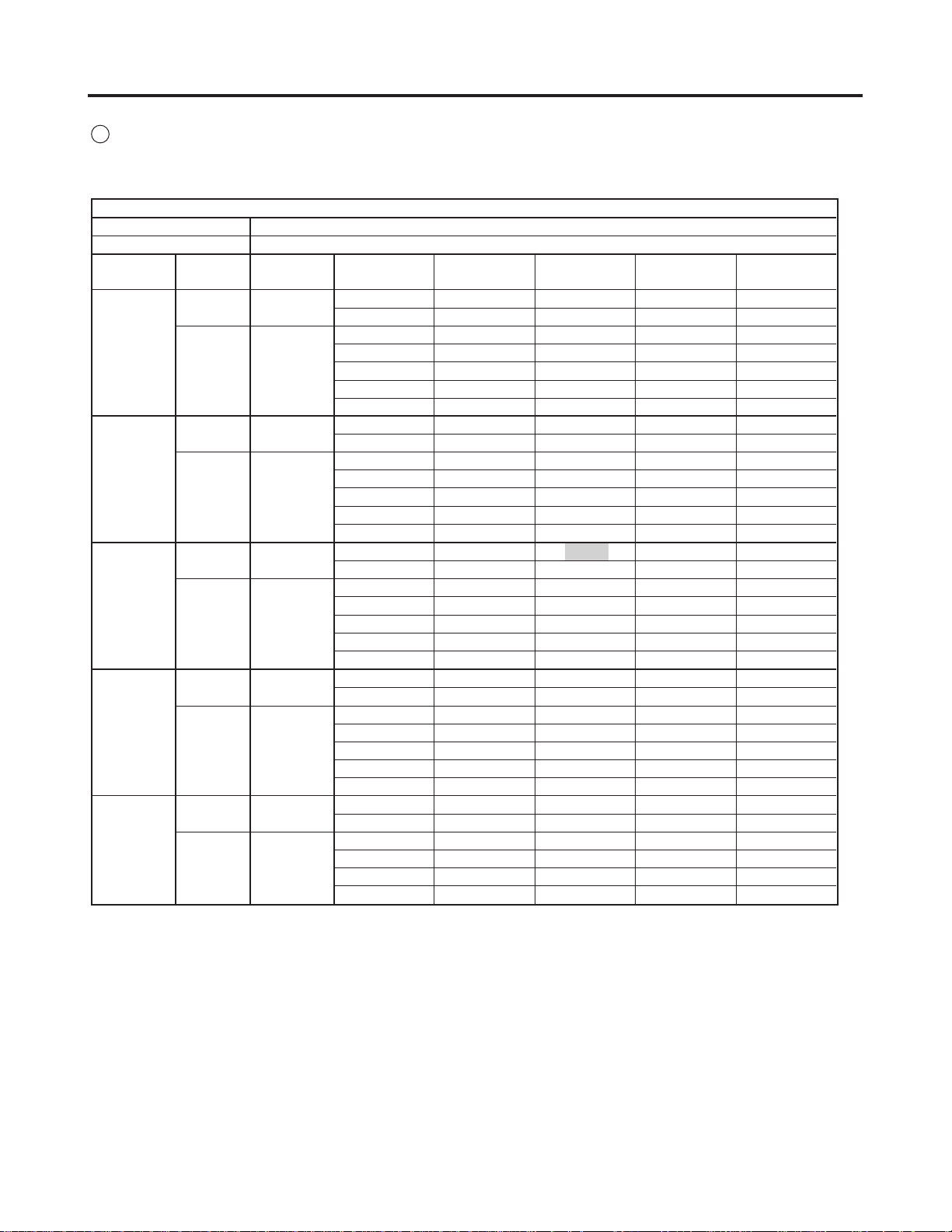
9. ELECTRICAL DATA
Electrical characteristics
Indoor model: KS2462R / Outdoor model: C2462R, CL2462R
Indoor Unit Outdoor Unit
Fan Motor Fan Motor Compressor
Performance at 230 - 208 V / 1 phase / 60 Hz
A 0.38 - 0.37 0.90 - 0.90 8.8 - 9.6 10.1 - 10.9
Rating conditions
kW 0.08 - 0.07 0.18 - 0.17 2.02 - 2.00 2.25 - 2.24
A 0.38 - 0.37 0.90 - 0.90 11.1 - 12.4 12.4 - 13.7
Full load conditions
kW 0.08 - 0.07 0.18 - 0.17 2.55 - 2.58 2.81 - 2.32
Starting amperes A 1 - 1 1 - 1 61 - 55 63 - 57
Complete Unit
Rating Conditions : Indoor Air Temperature 80 °F DB / 67 °F WB
Outdoor Air Temperature 95 °F DB
Full Load Conditions : Indoor Air Temperature 80 °F DB / 67 °F WB
Outdoor Air Temperature 115 °F DB
– 29 –
SM830092
Page 30

10. ELECTRICAL WIRING DIA GRAMS
(1) Indoor Unit
KS2462R
1
• Electric Wiring Diagram
FAN MOTOR
FMI
GRN / YEL
G
G
TERMINAL
PLATE
WHT
BLK
G
GRN
RED
1
2
G
4
FROM
OUTDOOR UNIT
BLK
VLT
YEL
ORG
87654321
87654321
CONNECTOR
[WHT]
FLP
PNK
BRN
GRY
WHT
CONNECTOR
[WHT]
CAPACITOR
PNK
BRN
GRY
WHT
VLT
ORG
YEL
BLK
[WHT] [WHT]
1
1
2
2
3
3
4
4
5
5
WHT
BLU
BLU
BLU
BLU
FLAP MOTOR [UPPER]
CONNECTOR
[WHT] [GRN] [BLK]
FLP
*
FLAP MOTOR [LOWER]
WHT
1
1
BLU
2
2
BLU
3
3
BLU
4
4
BLU
5
5
1
2
3
4
5
1
2
3
4
5
GRN
w
G
FM
w
w
HH
w
H
w
M
w
L
w
LL
1
2
FLAP1
3
5P [WHT]
4
5
1
2
FLAP2
3
5P [BLK]
4
5
135
135
SUP
5P [WHT]
PRY
3P [RED]
SEC
2P [WHT]
RECEIVER
3P [WHT]
LAMP
4P [WHT]
CONTROLLER
ROOM/COIL
4P [WHT]
WHT
1
WHT
313
121
3
2
1
1
2
3
4
BRN
BRN
2
3
WHT
2
GRY
1
GRY
WHT
1
GRY
2
GRY
3
GRY
4
P
S
1
1
2
2
3
3
4
4
5
5
6
6
7
7
COIL THERMISTOR (TH1)
BLK
1
1
BLK
2
2
BLK
3
3
BLK
4
4
ROOM THERMISTOR (TH2)
8512-5253-714XX-1 (KS2432A)
POWER
TRANSFORMER
IND LAMP ASSY
– 30 –
SM830092
Page 31

10. ELECTRICAL WIRING DIA GRAMS
Outdoor Unit
C2462R
• Electric Wiring Diagram
7
TERMINAL PLATE (6P)
TO INDOOR UNIT
L1
L2
G
POWER SUPPLY
60Hz 1ø 208V/230V
RED
1
2
WHT
G
WHT
4
L1
RED
L2
2Y
13
8
5
6
24
RED
WHT
BLK
RED
2P (WHT)
1
1
2
2
PS
PS
1
1
2
2
2P (GRN)
BLK
BLK
RED
RED
63PH
63PL
EARTH
TERMINAL
GRN/YEL
EARTH
TERMINAL
YEL
52C
BRN
A
B
C
RED
U
RED
R
CM
WHT
BLK
BLK
BLU
S
BLU
TWSVR
RC1
WHT
13
14
RED
BRN
BRN
23S
BLK
3
L
H
6
2
C
31
776
8
8
YEL
1Y
8P
(WHT)
7
5
14
8
32
RC2
PNK
BRN
GRY
GRY
WHT
VLT
P
1
32
54
6
3
1
54
2
S
PNK
BRN
GRY
GRY
WHT
VLT
FMO
49FO
– 31 –
854-2-5269-160-00-0
SM830092
Page 32

10. ELECTRICAL WIRING DIA GRAMS
Outdoor Unit
C2462R
• Schematic Diagram
TERMINAL
PLATE (6P)
– 1
– 2
– G
– 4
– L1
– L2
52C
2Y
2Y
2Y52C
1
63PH
2
2
63PL
1
1
49FO
2
1Y
HM
65
FMO
C
23S
LH
RC1
R
S
C
1Y
12
RC2
CM
52C
854-2-5269-160-00-0
Symbols Description
CM
FMO
52C
49FO
63PH
63PL Low Pressure Switch
23S
RC1, 2
1Y, 2Y
Compressor Motor
Outdoor Fan Motor
Compressor Motor Magnetic Contactor
Outdoor Fan Motor Thermal Protector
High Pressure Switch
Fan Speed Control Thermostat
Running Capacitor
Auxiliary Relay
Terminal Base
Connector
– 32 –
SM830092
Page 33

10. ELECTRICAL WIRING DIA GRAMS
Outdoor Unit
CL2462R
BLK
21
BLK
TEMP
2P (WHT)
BRN
21
BRN
SEC
2P (WHT)
WHT
31
WHT
PRY
3P(WHT)
RED
31
RED
HGBV
3P(YEL)
CONTROLLER (CR-CL2432)
9
7
5
HCOM M L
FMO
31
9P(WHT)
AC14V
AC208V
BRN
TH
TR
AC230V
YEL
VLT
WHT
BLK
GRY
BRN
PNK
HGBV
S7
P
87
8
65
65
43
43
21
21
YEL
VLT
WHT
GRY
GRY
BRN
PNK
854-2-5269-159-00-0
49FO
FMO
13
ST 31
R
1Y
BRN
24
13
8
BRN
BLK
WHT
52C
EARTH
TERMINAL
14
UV W 32
B
RC2
ORG
RED
WHT
BLK
RED
MGSW
3
ORG
E
GRN/YEL
ORG
ORG
6
5
7
3P(RED)
SUP
2
1
RED
3P(BLU)
1
GRY
• Electric Wiring Diagram
GRN/YEL
A
RED
BRN
RED
WHT
RED
WHT
WHT
8P
P
21
2P
P
21
2P
P
21
2P
(WHT)
S
21
(GRN)
S
21
(WHT)
S
21
(WHT)
RC1
RED
RED
BLK
BLK
WHT
WHT
WHT
BLK
R
63PL
63PH
CH
S
CM
C
PLATE (6P)
1
2
TERMINAL
4
G
L1
L1
L2
TO INDOOR UNIT
L2
G
60Hz 1ø 208V/230V
POWER SUPPLY
– 33 –
EARTH
TERMINAL
SM830092
Page 34

10. ELECTRICAL WIRING DIA GRAMS
Outdoor Unit
CL2462R
TERMINAL
PLATE (6P)
-1
-2
-G
-4
-L1
-L2
52C
C
1Y
R
CM
• Schematic Diagram
F1 (3A)
1
1 3
3
52C
52C
1
CH
63PL
1Y
RC1
S
2
F2 (3A)
3
49FO
1
63PH
2
1Y
4
2
1
3
52C
RY2
HLM
RC2
RY1
FMO
1
75 9
65 7
RY3
1
HGBV
2
3
1
COMCOM
RY1
RY2
RY3
CR-CL2462R
CONTROLLER
TEMP
L
PRY
M
HGBV
DC12V
SEC
TH
1
2
OUTDOOR
TEMPERATURE
TR
1
AC 208V
3
230V
1
AC 14V
2
854-2-5269-159-00-0
Symbols Description
CM
CH
FMO
52C
49FO
63PH
63PL
HGBV
TR
TH
RC1, 2
RY1~3, 1Y
CR-CL2432
F1, 2
Compressor Motor
Crankcase Heater
Outdoor Fan Motor
Compressor Motor Magnetic Contactor
Outdoor Fan Motor Thermal Protector
High Pressure Switch
Low Pressure Switch
Hot Gas Bypass Valve
Power Transformer
Thermistor (Outdoor Temperature)
Running Capacitor
Auxiliary Relay
Outdoor Controller
Fuse
Terminal Base
Connector
Terminal
– 34 –
SM830092
Page 35

11. PROCESSES AND FUNCTIONS
(1) Room Temperature Control
The Unit adjusts room temperature by turning the outdoor unit’s compressor ON and OFF.
This process is controlled by the thermostat located in the indoor unit.
The figures shows how each part of the system performs when the room temperature
changes and the thermostat activates the compressor to start (thermo ON) or stop (thermo
OFF). Fig. 1 shows about the cooling cycle.
Signal from remote control unit
3 minutes 3 minutes 3 minutes 3 minutes 3 minutes 3 minutes 3 minutes
T + 2 °F
T °Fset temp.
More than
5 minutes
ON OFF ON OFF ON OFFCompressor
Thermo.
OFF
Thermo.
ON
Thermo.
OFF
3 minutes5 minutes
Thermo.
ON
Thermo.
ON
Room temp.
Thermo.
ON
Thermo.
OFF
Outdoor fan
Indoor fan
ON OFF ON OFF ON OFF
Set speed
Chart Summary and Explanations
Once the compressor starts, it keeps running for 5 minutes.
Once the compressor stops, it will not start running again for 3 minutes.
If you change the operation mode during the cooling cycle, the control circuit stops the
compressor for 3 minutes.
For 5 minutes after the compressor is first turned on, and for 3 minutes after it is turned off,
the compressor is not controlled by the room sensor.
Thermo ON: When room temperature rises 1 °F above the set temperature T˚, (T ˚+1 °F):
Compressor ON
Thermo OFF: When the room temperature is equal to or below the set temperature T˚:
Compressor OFF
2212_M_S
Fig. 11
– 35 –
SM830092
Page 36

11. PROCESSES AND FUNCTIONS
(2) Dry Operation (Dehumidification)
Dry operation uses the ability of the cooling cycle to remove moisture from the air, but by
running at low level to dehumidify without greatly reducing the room temperature. The air
conditioner repeats the cycle of turning ON and OFF automatically as shown in the chart
below according to the room temperature.
Room temp.
Cooling operation
T + 4 °F
Set temp. T °F
T – 2 °F
Room temp. 59 °F
Dry A zone
Compressor :
FMI (indoor fan) :
Dry B zone
Compressor :
FMI (indoor fan) :
Monitor zone
Both the indoor and outdoor units stop.
Continuous operation
L (low speed) / LL (very low speed) intermittent ventilation
only while the compressor is ON.
Intermittent operation (ON for 3 minutes and OFF for 9 minutes)
L (low speed) / LL (very low speed) intermittent ventilation
only while the compressor is ON.
Fig. 12
2213_M_S
NOTE
Intermittent ventilation occurs by switching the indoor fan speed between L LL.
Dry operation does not occur when the room temperature is under 59°F, which is the monitor zone.
When the compressor stops, the indoor fan stops as well.
– 36 –
SM830092
Page 37

11. PROCESSES AND FUNCTIONS
(3) Freeze Prevention
Freeze Prevention keeps the indoor heat exchange coil from freezing. Freezing reduces the
efficiency of the unit, and frost buildup on the coil blocks cool air circulation from the indoor
unit’s fan.
Thermo. OFF
Room temp.
T + 4 °F
Set temp. T °F
Thermo. ON
Indoor heat exch.
coil temp.
30 °F
Compressor
Indoor fan
When the compressor has been running for 6 minutes or more and the temperature of the
indoor heat exchange coil falls below 30°F, the control circuit stops the compressor for at
least 6 minutes. The compressor does not start again until the temperature rises above
46°F or 6 minutes has elapsed.
More than
6 minutes
More than
10 minutes
ON ON ON ON
Set speed
More than
10 minutes
6 minutes
OFFOFF
Set speed
Fig. 13
Chart Summary and Explanations
2214_M_S
– 37 –
SM830092
Page 38

11. PROCESSES AND FUNCTIONS
(4) Outdoor Fan Speed Control
(1) C2462R Type
• In low outdoor temperature, the outdoor fan is set automatically from HIGH to LOW
to prevent the indoor heat exchanger from freezing.
• When the outdoor temperature falls below 78 °F, the outdoor fan is set from HIGH to
LOW automatically. When the outdoor temperature rises to 82 °F, the outdoor fan is
set from LOW to HIGH automatically.
(2) CL2462R Type
• In low outdoor temperature, the outdoor fan is set automatically from HIGH to MED,
LOW to prevent the indoor heat exchanger from freezing.
• When the outdoor temperature falls below 77 °F, the outdoor fan is set from HIGH to
MED automatically. When the outdoor temperature rises to 81 °F, the outdoor fan is
set from MED to HIGH automatically.
• When the outdoor temperature falls below 59 °F, the outdoor fan is set from MED to
LOW automatically. When the outdoor temperature rises to 63 °F, the outdoor fan is
set from LOW to MED automatically.
• When the outdoor temperature falls below 50 °F, the hot gas bypass valve opens
and keeps the pressures up by allowing some hot gas to be bypassed to the suction
of the compressor.
FAN ROTATION RPM
HGBV
(HOT GAS
BYPASS VALVE)
760
380
230
ON
M
L
OFF
47
(8.3)50(10)
OUTDOOR AIR TEMPERATURE °F DB
59
(15)63(17)
77
(25)81(27)
H
2217_X_S
– 38 –
Fig. 14
SM830092
Page 39

12. SERVICE PROCEDURES
(1) Troubleshooting
1) Check before and after Troubleshooting
Many problems may happen because of wiring or power supply problems, so you
should check these areas first. Problems here can cause false results in some of the
other tests, and so should be corrected first.
Check power supply wiring
1
(a) Single-phase
Check that power supply wires are correctly connected to L1 and L2 on the
6P terminal in the outdoor unit.
Check inter-unit wiring
2
Check that inter-unit wiring (AC 230 - 208 V Line voltage) is correctly connected between the indoor unit and outdoor unit.
Single-phase outdoor unit
Indoor Unit Outdoor Unit
1
2
G
4
Disconnect
switch
(Field supply)
Inter-Unit Wiring
(Line voltage)
230V/208V
230V/208V
Grounding line
230V/208V
(B)
6P Terminal4P Terminal
1
2
G
(A)
4
L1
L2
G
Power supply
Single phase
230V/208V 60Hz
Grounding line
2206_M_S
Fig. 15
Check power supply
3
Check that voltage is within the specified range (±10 % of the rating).
Check that power is being supplied.
If the following troubleshooting must be done with power being supplied, be
careful not to touch any uninsulated live part that can cause ELECTRIC
SHOCK.
Check the lead wires and connectors in indoor and outdoor units.
4
Check that the sheath of lead wires is not damaged.
Check that the lead wires are firmly connected at the terminal plate.
Check that the wiring is correct.
Reference
5
• Condition of general cooling operation (Thermo. ON)
SWEEP .................. ON
Indoor fan speed .... HIGH
– 39 –
SM830092
Page 40

12. SERVICE PROCEDURES
2) Air Conditioner does not Operate
Circuit breaker trips (or fuse blows).
1
(a) When the circuit breaker is set to ON, it is tripped soon.
• There is a possibility of ground fault.
• Check insulation resistance.
If resistance value is 2 MΩ or less, it is a defect of insulation.
(Example)
1 3
Outdoor
unit
L1
Circuit
breaker
*Set the circuit breaker to OFF.
Power
supply
cords
+
+
Ground
L2
G
2
1
+
2
+
G
4
+
Inter-unit
power line
Indoor
4
unit
1
+
2
+
G
4
+
1
Remove power supply cords
from the terminal plate in
the outdoor unit.
• Check insulation resistance
of power supply cords.
OK
Remove inter-unit power line
2
from the terminal plate in
the outdoor unit.
• Check insulation resistance
of outdoor unit.
OK
3
Remove inter-unit power line
from the terminal plate in
the indoor unit.
• Check insulation resistance
of indoor unit.
NO
NO Insulation of
NO
Execute
rewiring.
outdoor unit
is defective.
Insulation of
outdoor unit
is defective.
• Check insulation
resistance of
electrical parts
in the outdoor unit.
• Check insulation
resistance of
electrical parts
in the indoor unit.
OK
Inter-unit power lines are
defective.
Execute
rewiring.
1032_X_S
SM830092
– 40 –
Page 41

12. SERVICE PROCEDURES
(b) Circuit breaker trips in several minutes after turning the air conditioner on.
• There is a possibility of short circuit.
• Check capacity of circuit
breaker.
NO
Is capacity of circuit
breaker sufficient ?
• Check resistance of
outdoor fan motor winding.
• Check resistance of
compressor motor winding.
• Check resistance of flap
motor winding.
Neither indoor unit nor outdoor unit runs.
2
A. Power is not supplied
Replace it with a
suitable one.
(= larger capacity)
2218_X_S
• Check power supply.
Is power being supplied
NO
to outdoor unit ?
B. Check remote control unit.
• Try to run both indoor and
outdoor units with another
remote control unit.
OK
The other remote control
unit is defective.
– 41 –
Circuit breaker
is tripped.
Power failure.
Reset the breaker.
Wait for recovery
or consult power
supply company.
0615_X_S
0616_X_S
SM830092
Page 42

12. SERVICE PROCEDURES
C. Check “Operation selector” switch in the indoor unit.
• Has “Operation selector”
switch been set to ON
YES
position ?
NO
Set “Operation selector”
switch to ON.
But neither unit runs.
Switch Ass’y or P.C.B.
Ass’y in the indoor unit
is defective.
D. Check compressor motor protectors.
(a) High pressure switch (63PH)
• Check high pressure switch.
Does high pressure switch
actuate ? (63PH)
Disconnect the socket from 2P (WHT) connector.
Check the continuity between No.1 and No.2 poles
of the socket.
IND. LAMP Ass’y or P.C.B.
Ass’y in the indoor unit
is defective.
0617_X_S
YES
• Is outdoor heat exchanger
coil dirty or are there
obstacles near air suction
inlet of outdoor unit ?
NO
• Check if outdoor fan rotates.
Refer to “Only outdoor fan
does not run.”
E. Transformer in indoor unit.
• Check resistance of
transformer winding. (TR1)
1033_X_S
YES
Clean heat exchanger coil
or remove obstacles.
0618_X_S
– 42 –
SM830092
Page 43

12. SERVICE PROCEDURES
F. Check. auxiliary relay. (1Y or 2Y)
• Check coil resistance of
auxiliary relay.
(1Y or 2Y)
G. Check fuse on the P.C.B. Ass’y in the indoor unit.
0620_X_S
• Check fuse on the P.C.B.
Ass'y in the indoor unit
for continuity.
When the fuse blows.
• Check resistance of
primary and secondary
winding of transformer.
OK
• Check resistance of indoor
fan motor winding.
OK
• Check coil of compressor
motor magnetic contactor.
(52C)
OK
• P.C.B. Ass'y is defective.
2219_X_S
– 43 –
SM830092
Page 44

12. SERVICE PROCEDURES
3) Outdoor Unit does not Run.
A. Check COOL / FAN selector switch in the remote control unit.
• Is MODE selector button
set to COOL ?
B. Check set temperature.
Try to lower set
temperature by Temperature
setting button “COOLER”.
YES
• Set “Operation selector”
switch to TEST in the
indoor unit.
Outdoor unit runs.
Is room temperature too
low ?
NO
Set to COOL.
2220_X_S
NO
• Try to run both indoor and
outdoor units with another
remote control unit.
OK
The other remote control
unit is defective.
2221_X_S
– 44 –
SM830092
Page 45

12. SERVICE PROCEDURES
C. Check compressor motor magnetic contactor.
• Check coil resistance of
compressor motor magnetic
contactor. (52C)
D. Check indoor unit P.C.B.
• Check P.C.B. Ass’y.
• Check voltage between
terminals No.2 and No.4 at
terminal plate.
1035_X_S
No voltage appears.
P.C.B. Ass’y is defective.
0628_X_S
E. Check outdoor unit P.C.B. (CL2462R Type)
• Check P.C.B. Ass’y.
• Check voltage between
terminals L1 and L2 at
terminal plate.
No voltage appears.
P.C.B. Ass’y is defective.
1036_X_S
– 45 –
SM830092
Page 46

12. SERVICE PROCEDURES
4) Indoor Unit does not Run.
(Indoor fan and flap motor do not run.)
P.C.B. Ass’y is defective.
0630_X_S
5) Some Part does not Operate.
A. Indoor fan does not run.
• Check fan rotation.
Rotate the fan gently once
or twice by hand.
Fan cannot
be rotated.
Check fan casing
for foreign matter
on the inside.
Fan motor burnout
or foreign matter
in bearing.
Remove foreign
matter or repair.
Repair or replace.
• Check resistance of fan
motor winding.
OK
• Check fan motor capacitor.
OK
Relay RY1 or RY2 on the
P.C.B. Ass’y is defective.
B. Flap motor does not run.
• Check resistance of
flap motor winding.
OK
P.C.B. Ass’y or remote
control unit is defective.
0631_X_S
2222_X_S
– 46 –
SM830092
Page 47

12. SERVICE PROCEDURES
6) Outdoor Fan does not Run.
• Check fan rotation.
Rotate the fan gently once
or twice by hand.
• Check resistance of fan
motor winding.
OK
• Check fan motor capacitor
• Check continuity between
terminals on the compressor
motor magnetic contactor.
Fan cannot
be rotated.
• Check fan casing
for foreign matter
on the inside.
• Fan motor burnout
or foreign matter
in bearing.
Remove foreign
matter or repair.
Repair or replace.
0633_X_S
7) Outdoor Fan Speed is not Switched from High to Low even when the Outdoor
Temperature Falls below 78
• Check the thermostat (23S).
1037_X_S
°F. (C2462R Type)
8) Outdoor Fan Speed is not Switched from High to Med even when the Outdoor
Temperature Falls below 77
°F.
Outdoor Fan Speed is not Switched from Med to Low even when the Outdoor
Temperature Falls below 59
• Check outdoor unit P.C.B.
Ass’y
°F. (CL2462R Type)
OK
• Check resistance of outdoor
temp sensor.
0722 _X_S
SM830092
– 47 –
Page 48

12. SERVICE PROCEDURES
9) Outdoor Fan does not Run for CL2462R.
• Check fuse on PCB Ass’y in
outdoor unit for continuity.
If fuse blows,
• Check resistance of primary
winding of transformer. (TR)
10) Compressor does not Run.
1038_X_S
• Check compressor motor capacitor
(RC1).
OK
• Check PTC.
OK
• Check resistance of compressor
motor winding.
Wait for 30 minutes until com pressor has cooled.
Compressor runs.
Compressor internal thermal
protector is operated.
• Check power supply voltage.
Is voltage abnormally low?
NO
• Is outdoor heat exchanger coil dirty
or are there obstacles near air
suction inlet?
1039_X_S
– 48 –
SM830092
Page 49

12. SERVICE PROCEDURES
11) Poor Cooling.
Check installation position
of remote control unit.
• Does cool air from air condi tioner reach remote control
unit directly ?
• Is wide tube between indoor unit
and outdoor unit insulated ?
YES
• Measure temperatures of suction
and discharge air of indoor unit.
Temperature difference between
suction and discharge air is
large enough (Approx. 10 deg. or more).
• Check clogging of air
filter.
• Is fan speed set to LOW ?
YES
NO
Temperature
difference
is small.
Possibility of
refrigerant
shortage.
Air filter is clogged.
YES
Change installation
position of remote
control unit.
Insulate wide tube and
then execute taping with
narrow tube.
Charge
refrigerant
Clean filter.
Set fan speed to either
HIGH or MEDIUM.
• Review cooling load estimate,
if performance of air conditioner
is normal.
12) Excessive Cooling.
• The set temperature is too low.
• Is the remote control unit installed
at a place where it can
detect the room temperature
properly ?
YES
NO
– 49 –
Reduce cooling load or
replace the unit with
higher cooling capacity.
1040_X_S
Set the temperature to
higher value using
temperature setting
button of the remote
control unit.
Change installation
position of the remote
control unit.
0637_X_S
SM830092
Page 50

12. SERVICE PROCEDURES
(2) A Sensor is Defective.
Indoor (heat exchanger) coil temp. Sensor is defective.
1
(a) Open (=No continuity in sensor)
Compressor and outdoor fan repeat ON for 10 minutes and OFF for 6 minutes
when sensor opens.
(b) Short
“Freeze Prevention” does not operate when dehumidified water is frozen on the
indoor coil.
Room temp. Sensor (in the remote control unit) is defective.
2
(a) Open (=No continuity in sensor)
Neither outdoor fan nor compressor runs.
(b) Short
Outdoor fan and compressor do not stop. — Excessive cooling.
– 50 –
SM830092
Page 51

12. SERVICE PROCEDURES
(3) Checking the Electrical Components
1) Measurement of Insulation
Resistance
•
The electrical insulation is acceptable
when the resistance exceeds 2 MΩ.
Power Supply Wires
1
Clamp the earthed wire of the Power
Supply wires with a lead clip of the
insulation resistance tester and measure the resistance by placing a probe
on either of the power wires. (Fig. 16)
Then measure the resistance between
the earthed wire and the other power
wires. (Fig. 16)
Indoor Unit
2
Clamp an aluminum plate fin or copper
tube with the lead clip of the insulation
resistance tester and measure the
resistance by placing a probe on the
terminal plate (Fig. 17)
Probe
Copper
tube or
metallic part
Clip
Clip
Earthed wire
Insulation
tester
Terminal plate
0638_X_S
Insulation
tester
Probe
0639_X_S
Fig. 16
Fig. 17
Outdoor Unit
3
Measure the resistance by placing a
probe on the terminal plate in the same
manner as explained above 2 . (Fig. 17)
Measurement of Insulation Re-
4
sistance for Electrical parts
• Disconnect the connector of the
desired electric part from terminal
plate, P.C.B. Ass’y, etc. (Fig. 18)
•
Similarly, disconnect the lead wires from
compressor, capacitor, etc. (Fig. 19)
• Measure the resistance in the same
manner as illustrated on the right.
Refer to Electrical Wiring Diagram.
NOTE
If the probe does not enter the hole
because the hole is too narrow, use a
probe with a thinner pin.
Metallic
part
– 51 –
Clip
Copper
tube or
metallic part
Clip
Insulation
tester
From fan motor,
compressor and other
parts.
Probe
Insulation
tester
Probe
0640_X_S
0641_X_S
Fig. 18
Fig. 19
SM830092
Page 52

12. SERVICE PROCEDURES
2) Checking the Protective Devices
• Disconnect the connector, which consists of P (plug) and S (socket) when you want to check the
protective device.
• Then check continuity among plug’s (and/or socket’s) terminal as in Fig. 20.
• The Protective Device is proved normal if there is a continuity between terminals.
socket
Multimeter
Ω
0642_X_S
Indoor fan motor thermal protector (49FI) . . . . . . Indoor unit
1
• Disconnect the connector which leads to the indoor fan motor (FMI).
• Check the socket’s terminals.
Compressor motor thermal protector . . . . . . Outdoor unit
2
• Disconnect the wires from terminals of compressor.
• Check the terminals of compressor.
Outdoor fan motor thermal protector (49FO) . . . . . . Outdoor unit
3
• Disconnect both the connector which leads to the outdoor fan motor (FMO).
• Check socket’s terminal.
Fig. 20
– 52 –
SM830092
Page 53

12. SERVICE PROCEDURES
3) Checking the Electrical Parts
Power transformer ...........................Indoor unit *Measure the coil resistance.
1
• Primary230-208 V ; Measure the resistance between two WHT lead wire terminals
of socket connected to power transformer.
• Secondary 19 V ; Measure the resistance between two BRN lead wires.
Power transformer (TR) ................. Outdoor unit *Measure the coil resistance.
2
• Primary 230-208 V ; Measure the resistance between two WHT lead wire terminals
of socket jointed to power transformer.
• Secondary 19 V ; Measure the resistance between two BRN lead wires.
Indoor fan motor (FMI) ............... Indoor unit *Measure the coil resistance.
3
• Measure the resistance between each terminal of the socket connected to the
indoor fan motor.
Outdoor fan motor (FMO) ........... Outdoor unit *Measure the coil resistance.
4
• Measure the resistance in the same manner as explained above 2 .
Motor capacitor ............ Both in indoor and outdoor unit
5
• Remove the lead wires from the
capacitor terminals, and then place a
probe on the capacitor terminals as
shown in Fig. 21. Observe the deflection of the pointer, setting the resistance measuring range of the multimeter to the maximum value.
• The capacitor is “good” if the pointer
bounces to a great extent and then
gradually returns to its original position.
NOTE
The range of deflection and the deflection
time differ according to the capacity of the
capacitor.
Multimeter
Ω
– 53 –
Compressor motor
capacitor
Fig. 21
Fan motor
capacitor
1041_X_S
SM830092
Page 54

12. SERVICE PROCEDURES
Continuity of fuse on P.C.B.
6
Ass’y
• Check for continuity using a multimeter as shown in Fig. 22.
NOTE
Method Used to Replace Fuse on
PCB Ass’y
1. Remove the PCB Ass’y from the
electrical component box.
2. Remove the fuse from PCB Ass’y
using pliers while heating the soldered leads on the back side of the
PCB Ass’y with a soldering iron (30W
or 60W). (Fig. 23)
3. For replacement, insert a fuse of the
same rating to the intended position
and solder it.
(Allow time to radiate heat during soldering so that the fuse does not melt.)
When replacing the
CAUTION
fuse, be sure not to
break down the
varistor.
Fuse
1042_X_S
Fig. 22
Soldering iron
PCB Ass’y
Fuse Varistor
Pliers
1043_X_S
Fig. 23
– 54 –
SM830092
Page 55

12. SERVICE PROCEDURES
CAUTION
11. REFRIGERANT R410A: SPECIAL PRECAUTIONS WHEN INSTALLING UNIT
11-1. Characteristics of New Refrigerant R410A
11-1-1. What is New Refrigerant R410A?
R410A is a new refrigerant that contains two types of pseudo-non-azeotropic refrigerant mixture which do
not adversely affect the earth’s ozone layer. Its refrigeration capacity and energy efficiency are about the
same level as the conventional refrigerant, R22.
11-1-2. Components (mixing proportions)
HFC32 (50%) / HFC125 (50%)
11-1-3. Characteristics
Less toxic, more chemically stable refrigerant
The composition of refrigerant R410A changes whether it is in a gaseous phase or liquid phase. Thus, when
there is a refrigerant leak the basic performance of the air conditioner may be degraded because of a change
in composition of the remaining refrigerant.
remaining refrigerant with the refrigerant recovery unit. Then, after evacuation, totally recharge the specified
amount of refrigerant with the new refrigerant at its normal mixed composition state (in liquid phase).
Therefore, do not add new refrigerant.
Instead, recover the
When refrigerant R410A is used, the composition will differ depending on whether it is in gaseous or liquid
phase, and the basic performance of the air conditioner will be degraded if it is charged while the refrigerant
is in gaseous state.
Thus, always charge the refrigerant while it is in liquid phase.
Ether-type oil is used for compressor oil for R410A-type units, which is different
from the mineral oil used for R22. Thus more attention to moisture prevention and
faster replacement work compared with conventional models are required.
11-2. Checklist Before Installation
Use a clutch-type flare tool for R410A or the conventional flare tool. Note that sizes of the resultant flares differ
between these two tools. Where a conventional flare tool is used, make sure to observe A Specification
(amount of protrusion).
Diameter of tube (ø) D
ø6.35 (1/4") 0 – 0.5 mm 1.0 – 1.5 mm
ø19.05 (3/4") 0 – 0.5 mm 1.0 – 1.5 mm
Size of flare
Flare tool for R410A Conventional flare tool (for R22)
D
A Specification
D
A
Flare tool for R410A
A
Conventional flare tool (R22)
Flare nut: Because the new refrigerant R410A operates at 1.6 times higher pressure than the conventional
refrigerant R22, the flare nuts that came with the unit must be used.
– 55 –
SM830092
Page 56

12. SERVICE PROCEDURES
Tubing precautions
Refrigerant R410A is more easily affected by dust or moisture compared to R22, thus be sure to temporarily
cover the ends of the tubing with caps or tape prior to installation.
Never use 0.7mm-thick copper tubing or tubing which is less than 0.8mm in thickness, since air conditioners
with R410A are subject to higher pressure than those using R22 and R407C.
Outer diameter: mm (inch) Tubing wall thickness: mm (inch)
Narrow tube ø6.35 (1/4") 0.8 (0.032)
Wide tube ø19.05 (3/4") 1.0 (0.042)
No addition of compressor oil for R410A
No additional charge of compressor oil is required.
No use of refrigerant other than R410A
Never use a refrigerant other than R410A.
If refrigerant R410A is exposed to fire
Through welding, etc., toxic gas may be released when R410A refrigerant is exposed to fire. Therefore, be
sure to provide ample ventilation during installation work.
Caution in case of R410A leak
Check for possible leak points with the special leak detector for R410A. If a leak occurs inside the room,
immediately provide thorough ventilation.
– 56 –
SM830092
Page 57

12. SERVICE PROCEDURES
11-3. Tools Specifically for R410A
For servicing, use the following tools for R410A
Tool Distinction Tool Name
Gauge manifold
Charging hose
Gas leak detector
Refrigerant cylinder
Charging cylinder
Refrigerant recovery unit
Tools specifically for R410A
Tools which can be commonly used for R22,
R407C, and R410A
Vacuum pump with anti-reverse flow ( 1)
(Solenoid valve-installed type, which prevents oil from flowing back into the
unit when the power is off, is recommended.)
Vacuum pump ( 2) … can be used if the following adapter is attached.
Vacuum pump adapter (reverse-flow prevention adapter) ( 3).
(Solenoid valve-installed adapter attached to a conventional vacuum pump.)
Electronic scale for charging refrigerant
Flare tool
Bender
Torque wrench
Cutter, reamer
Welding machine, nitrogen gas cylinder
CAUTION
To prevent other refrigerants (R22, R407C) from being mistakenly charged to this unit, sizes of the service
ports and flare nuts of the narrow tube service valve and wide tube service valve have been altered.
The above tools specifically for R410A must not be used for R22 and R407C.
Doing so will cause malfunction of the unit.
For the above vacuum pump ( 1, 2) and vacuum pump adapter ( 3), those for
R22-type units can be used for R407C-type. However, they must be used exclusively for R410A and never alternately with R22 and R407C.
SM830092
– 57 –
Page 58

– 58 –
SM830092
 Loading...