

Page 1
SERVICE MANUAL Colour Television
Product Code: 1 113 378 15
Original Ver sion
Chassis Series: LC1-B
F5TT
FILE NO.
Model No. C20LB87B
Service Ref. No.C20LB87B-00
(Argentina)
Give complete “SERVICE REF. NO.” for parts
order or servicing. It is shown on the rating
plate at the cabinet back of the unit.
This T.V. receiver will not work properly in
foreign countries where the television transmission system and power source differ from
the design specifications.Refer to the specification table.
VIDEO
MODE
AUDIO
MODE
POWER
0
7
1
4
8
5
2
3
6
9
▲CH▼
+VOL
RECALL
MENU
IMAGE
SLEEP
DISPLAY
MUTE
FXMR
VOL-
Specifications
Power Source . . . . . . . . . AC220V, 50Hz / 60Hz
Receiving System . . . . . . PAL (M/M, N/N), NTSC (M/M)
Channel Coverage
Antenna mode VHF:CH02-CH13, UHF: CH14-CH69
CATV mode VHF band:CH01-CH13, Mid band: CH14-CH22
Super band: CH23-CH36, Hyper band: CH37-CH64
Ultra band: CH65-CH94 and CH100-CH125
Low mid band: CH95-CH99
Video IF . . . . . . . . . . . . . 45.75MHz
Aerial Input Impedance . . 75Ω
Ext.Terminals
Video inputs: Phono jack ✕ 2(1Vp - p, 75Ω)
Audio inputs: Phono jack ✕ 2 (436mVr ms, more than 40KΩ)
Speaker . . . . . . . . . . . . . 5cm ✕ 9cm ✕ 2
Sound Output (Music) . . . 2.0W
Dimensions . . . . . . . . . 496(W) ✕ 464(H) ✕ 472(D)mm
Weight . . . . . . . . . . . . . approx. 16.7Kg
Specifications subject to change without notice.
VIDEO
AUDIO
MENU
CH
-
VOL +
Page 2

Contents
-2-
Safety Notice . . . . . . . . . . . . . . . . . . . . . . . . . . . . . . . . . . . . . . . . . . . . . . . . . . . . . . . . . . . . . . . . . . . . . . . . 2
Chassis Block Diagram . . . . . . . . . . . . . . . . . . . . . . . . . . . . . . . . . . . . . . . . . . . . . . . . . . . . . . . . . . . . . . 3-4
IC Block Diagrams . . . . . . . . . . . . . . . . . . . . . . . . . . . . . . . . . . . . . . . . . . . . . . . . . . . . . . . . . . . . . . . . . . 5-6
Protection Circuit . . . . . . . . . . . . . . . . . . . . . . . . . . . . . . . . . . . . . . . . . . . . . . . . . . . . . . . . . . . . . . . . . . . . . 6
Service Adjustments with replacing Memory IC (IC802) . . . . . . . . . . . . . . . . . . . . . . . . . . . . . . . . . . . . . 7-12
Service Adjustments . . . . . . . . . . . . . . . . . . . . . . . . . . . . . . . . . . . . . . . . . . . . . . . . . . . . . . . . . . . . . . . . . 13
Purity and Convergence Adjustment . . . . . . . . . . . . . . . . . . . . . . . . . . . . . . . . . . . . . . . . . . . . . . . . . . . . . 14
Cabinet Parts List . . . . . . . . . . . . . . . . . . . . . . . . . . . . . . . . . . . . . . . . . . . . . . . . . . . . . . . . . . . . . . . . . . . 15
Chassis Electrical Parts List . . . . . . . . . . . . . . . . . . . . . . . . . . . . . . . . . . . . . . . . . . . . . . . . . . . . . . . . . 16-21
Safety Notice
SAFETY PRECAUTIONS
1: An isolation transformer should be connected in the
power line between the receiver and the AC line
when a service is performed on the primar y of the
converter transformer of the set.
2: Comply with all caution and safety-related notes pro-
vided on the cabinet back, inside the cabinet, on the
chassis or the picture tube.
3: When replacing a chassis in the cabinet, always be
certain that all the protective devices are installed
properly, such as, control knobs, adjustment covers
or shields, barriers, isolation resistor-capacitor networks etc.. Before returning any television to the
customer, the service technician must be sure that
it is completely safe to operate without danger of
electrical shock.
X-RADIATION PRECAUTION
The primary source of X-RADIATION in television receiver is the picture tube.The picture tube is specially constructed to limit X-RADIATION emissions.For continued X-RADIATION protection, the replacement tube must be
the same type as the original including suffix letter.Excessive high voltage may produce potentially hazardous X
- RADIATION. To avoid such hazards , the high voltage must be maintained within specified limit.Refer to this service manual, high voltage adjustment for specific high voltage limit. If high voltage exceeds specified limits, take
necessary corrective action.Carefully follow the instructions for + B1 v olt po w er supply adjustment, and high voltage check to maintain the high voltage within the specified limits.
PRODUCT SAFETY NOTICE
Product safety should be considered when a component replacement is made in any area of a receiver.
Components indicated by mark in the parts list and the schematic diagram designate components in which
safety can be of special significance. It is par ticularly recommended that only par ts designated on the parts list
in this manual be used for component replacement designated by mark . No deviations from resistance
wattage or voltage ratings may be made for replacement items designated by mark .
Page 3
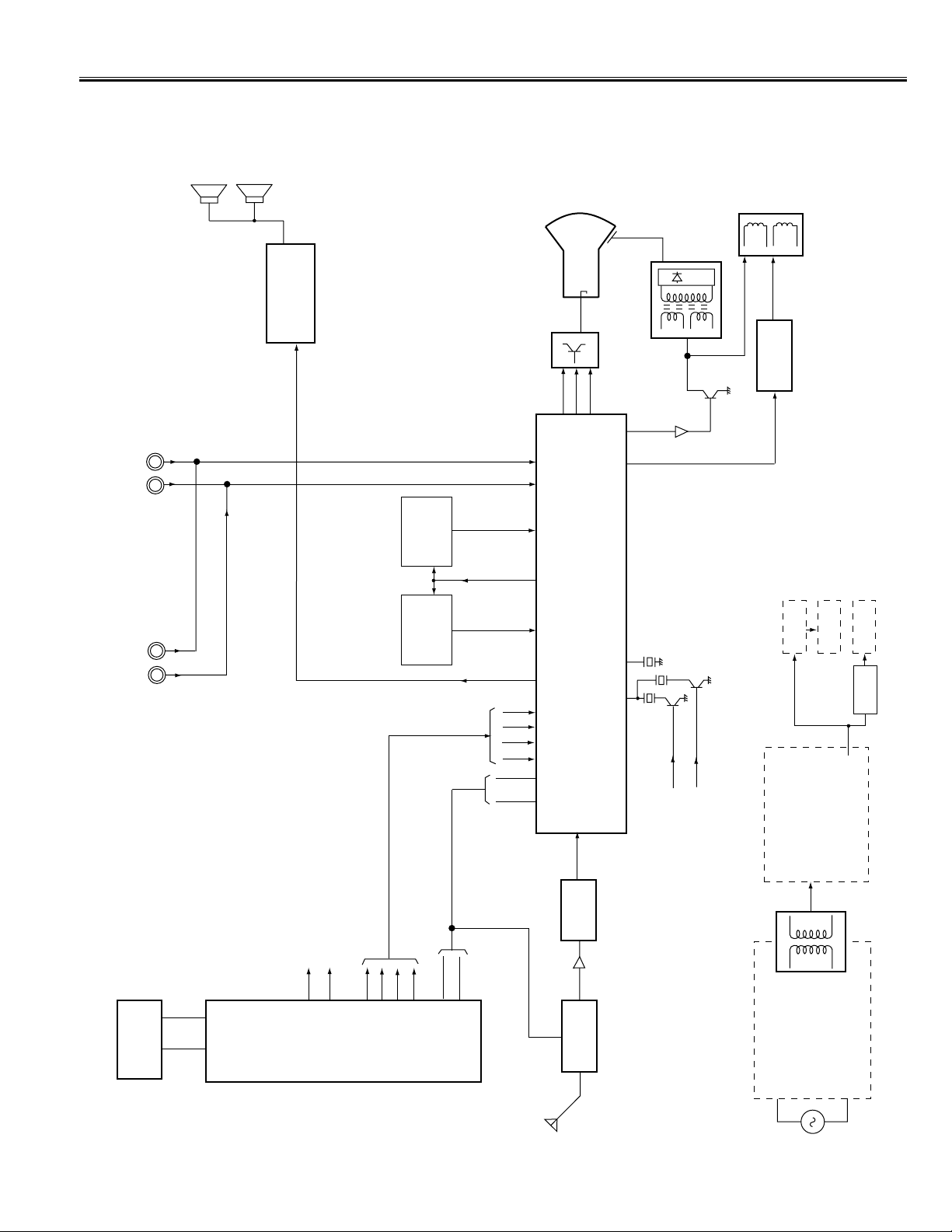
Chassis Block Diagrams
-3-
IC802
MEMORY
X' T AL-SW1 (PAL-M)
TUNER
(WITH PLL)
ANT
AC
POWER
CIRCUIT
T611
CONVERTER
TRANS.
B1:130V (MAIN HIGH)
B2: 15-18V (AUDIO)
B4: 25V (VERT.)
B5: 12V (MAIN LOW)
FROM IC801(CPU) PIN-33
PAL-M
PAL-N
NTSC
SAW
Filter
IIC BUS CONTROL
OSD
AUDIO
REAR AV IN
SIF
FILTER
4.5MHz
B6:9V
B7:5V
B8:5V
REG.IC
VERT. -OUT
AUDIO-OUT
SIF IN
VIF/SIF OUT
INT . VIDEO-IN
EXT . VIDEO-IN
SOUND
CARRIER
TRAP
4.5MHz
R
G
B
Q901
CRT
HV
T401 F.B.T
DEFLECTION
YOKE
Q432
HORIZ.-OUT
SP902
AUDIO
FRONT AV IN
VIDEO
SDA
SCL
3
4
IC801
CPU
QXXAVB602
X' T AL-SW2 (PAL-N)
33
34
R
G
B
BLK
192021
22
1
2
SDA
SCL
A101
X131
SDA
SCL
10
14
6/7
IF IN
IC201 QXXAVB488M
IF/VIDEO/CHROMA/DEFLECTION ( 1-CHIP IC )
R
G
B
BLK
272328
30
3436
52
3
45
12
21
VERT. OUT
HORIZ. OUT
18
19
20
IC501
LA7840
40
32
FROM IC801(CPU) PIN-34
IC651
IC001
LA4285
AUDIO AMP.
9
1
VIDEO
AUDIO
K1001
K1111
EXT. AUDIO-IN
47
5
6
CPU X'TAL SW
4
2
SP901
MAIN SIGNAL PROCESSING CIRCUIT
Page 4
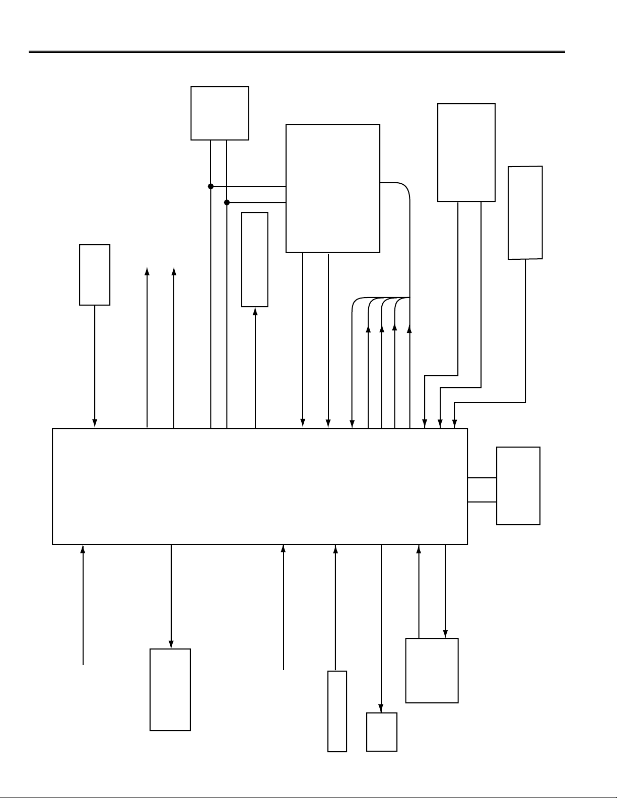
Chassis Block Diagrams
-4-
SYSTEM CONTROL
12
KEY SWITCH IN
KEY
SWITCH
BUS SCL
2
1
31
9
BUS SDA
POWER ON/OFF
PHOTO COUPLE
(ON=HIGH, OFF=LOW)
IC201
IF/VIDEO / CHROMA
IC801
CPU
QXXAVB602
22
19
20
21
18
17
27
34
7
6
32
28
ADJUSTMENT DATA IN
OSD BLK OUT
OSD RED OUT
OSD GREEN OUT
OSD BLUE OUT
DEFLECTION
CIRCUIT
HORIZ. SYNC IN (ACTIVE=LOW)
VERT. SYNC IN (ACTIVE=LOW)
POWER PROTECT IN
(POWER ERROR=LOW)
POWER CIRCUIT
etc.
SCL
SDA
IC802
MEMORY
OSC
32.768KHZ
CPU OSC OUT
CPU OSC IN
LED
ON-TIMER LED OUT (ON=LOW)
RC SIGNAL IN
(ACTIVE=LOW)
RC PRE-AMP.
30
VOLUME OUT
IC001
AUDIO AMP.
A101
TUNER
RESET IN (RESET=LOW)
13
X'TAL-SW1(PAL-M) ON=HIGH
33
X'TAL-SW2(PAL-N) ON=HIGH
34
15
VIDEO SIGNAL IN
11
OPTION IN
5
10
AFT S-CURVE IN
Page 5

IC Block Diagrams
-5-
IC201 < IF/Video/Chroma/Def. > QXXAVB488
VIF IN
IF AGC OUT
AFT
TV IN
EXT IN
AUDIO
OUT
33
29
35
26
37
40
32
13
44
43
11
15
16
12
2725242122412819201830239101445
QXXAVB488
SYNC IN
KILLER FILTER
IDENT FILTER
COLOUR APC
AF AMP
AF AMP
4.5/6.0
SIF IO ADJ
BUS
I/F
FM
DET
LIMITTER
B EXIT
INPUT
R EXIT
INPUT
G EXIT
INPUT
V SYNC
TRIG
SYNC
SEP.
SYSTEM
ID
EQ
ELIMINATE
BGP
GENE.
PHASE
CONT
KILLER
DET
LOCK
DET
ID
DET
CHROMA
APC
DET
PAL
SW
SECAM
FF
SELF
ADJ
V.RAMP
AFC
AFC
1H DL
VCXO
ACC
DET
F/F
2ND AMP
CHROMA
BPF
1ST AMP
(ACC)
HPF
AFT
AFT OUT
VIDEO
MUTE
H STOP
H.PHASE
AUDIO MUTE SW
SDA
SCL
FAST BLK
B IN
R IN
B-OUT
R- OUT
G-OUT
G-IN
H-VCC
SECAM REF
V.SIZESERVICE
SW
H-OSC
SELF ADJ.
CLAMP
50/60 OUT
R
TINT
B
R
DRIVE
B
G
ABCL
ABCL
ID CUT
BLUEBACK
WHITE
BACK
COLOR
CONTRAST
SERVICE
BRIGHT
STATION DET
STATION
SYSTEM SET
SYSTEM
IF AGC
DELAY ADJ
DEFEAT
DL TIME
DL FINE
VIDEO
VCC
VIDEO
GND
DEFLECTION
GND
TRAP
SW
D.TRAP
F.TRAP
BLACK STRECH OFF
F AGC
VIDEO
DET
VIF
AMP
APC
DET
ADJ
DET
BLACK
STRECH
VIDEO
TONE
CHROMA
TRAP
VIDEO
MUTE
CLAMP
SHARPNESS
CONTRAST
DELAY
FEF
FILTER
AGC
R-Y IN
B-Y IN
H OUTPUT
SYSTEM
DECODE
BRIGHT
CHROMA
DEMODULATOR
DR/VE
AMP
AFC GAIN
RGB MATRIX
CONTRAST
32 FH
VCO
MUTE
DET
HV
BLK
VERTICAL
COUNTDOWN
HORIZONTAL
COUNTDOWN
EXIT AUDIO
IN
GND
VCC
VIF
SIF
SIF IN
47
48
46
1
8
3
42
52
51
50
49
5
4672 931
38
36
34
39
V-OUT
V-FB
V RAMP
BLK
AUDIO
DIRECT
OUT
AF DC
FB
HI VCC
IF OUT
IF APC
IF VCO
IF VCO
BLACK
PEAK
ACL/CLK
Y-SW
OUT
X TAL 4.43
X TAL 3.58
BLACK PEAK
Page 6
IC Block Diagrams
-6-
IC501 < Ver tical Output > LA7840
THERMAL
PROTECTION
PUMP
UP
AMP
-
+
GND
Ver. Output
Output
Stage Vcc
Non Inv. Input
Inverting
Input
Vcc
Pump Up
Output
LA7841
1
2
34
5
6
7
IC001 < Audio AMP. > LA4285
A
B
1
2
3
INT
EXT
+
1µF
+
1µF
PRE GND
INT/EXT
SW
4
6
7
+5V
DC VOL
D. C
NF
8
9
POWER GND
0.1µF
10µF
+
+
47µF
1.0Ω
POWER OUT
+
100µF
1000µF
VCC
10
AMP
DC VOL
5
+
Protection Circuit
This TV set has a built-in power supply protection circuit.
It is provided to protect the TV set in case of a power supply circuit malfunctions.When something abnormality
occurs during TV reception, the TV set goes to the stand-by mode.
When an abnormality occurs during TV reception, it causes pin 27 of the CPU to go continually Low(less than
0.75V) for about one second.The CPU detects that this has occurred and outputs the signal from pin 31 to
switch off the power supply lines.
Releasing the protective circuit and restoring power supply
To release the protective circuit and restore power supply, turn the power to the TV set OFF and then ON again
via either the main power switch or the ON-OFF button on the remote control.This will work only if the power
supply trouble was temporary. If there is permanent trouble such as a damaged circuit, power cannot be
restored and the circuit will have to be repaired.
LA7840
Page 7
-7-
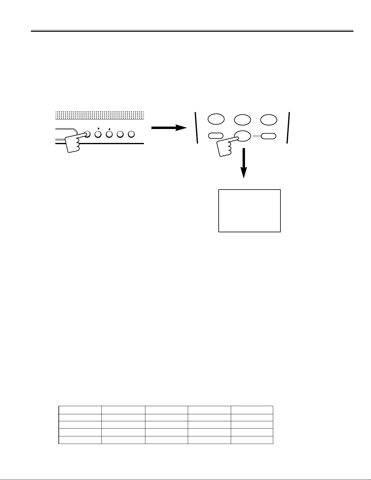
Service Adjustments with Replacing Memor y IC(IC802)
MENU
CH
-
VOL +
0
7
8
9
RECALL
SLEEP
Note:The CPU (IC801) and memory IC (IC802) store the service adjustments data and controls data for each circuit.
When the Memory IC(IC802) is replaced, some of the service adjustments should be readjusted to obtain the
best performance. The necessary service adjustments are carr ied out by using the RC handset. Please set
up the TV set with following steps [1] to [3].
[1] Initializing Procedure
1. Put a new memory IC.
2.Tur n on the TV set
3. Press and hold the MENU button on the TV set, then press 0 button on the remote control transmitter.
The following picture appears on the screen.
This completes the initialization of memory IC.
02
Following shows the initialized contents of memory data by this procedure.
1.TV/AV mode :TV mode
2. Antenna or cable setting : Antenna
3. Colour system : AUTO
4. Channel Memor y : Clear
5. Receiving Channel : Ch02
6. Sound Volume : 11/63 steps
7. Color : 30/63 steps
8. Contrast : 63/63 steps
9. Brightness : 32/63 steps
10. Shar pness : 31/63 steps
11.Tint : 31/63 steps
12. Language : Spanish
13. Password : Clear
14. Channel Block : Clear
15. Sleep Timer : Clear
16. Picture Mode : MANUAL
17.Video status (Picture mode data)
Item NORMAL STRONG SOFT MANUAL
Colour 28 34 22 28
Contrast 63 63 63 63
Brightness 35 15 40 35
Sharpness 31 31 31 31
Page 8
-8-
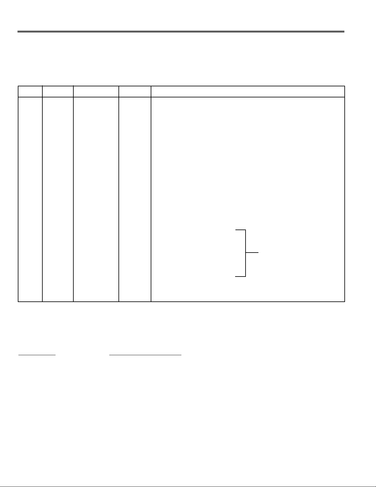
Service Adjustments with Replacing Memor y IC(IC802)
[2] Service Adjustments-1
Following table shows the initial values which have been stored in the CPU ROM, and items for the service
adjustments.
No. Item Initial value Range Description
01 H-P 08 00~15 Horizontal centre adjustment
02 V-P 04 00~07 Vertical centre adjustment
03 V-S 64 00~127 Vertical size adjustment
04 OSD 20 01~63 OSD position adjustment
05 AGC 64 00~127 RF AGC adjustment
06 VCO 128 00~255 VCO (AFT) adjustment
07 SIF 00 00 SIF VCO adjustment
08 SELF 00 00~15 SELF-adjusting
09 DLT 02 00~03 DL-time adjustment
10 DL F 00 00, 01 DL-fine adjustment
11 B
-
ST 00 00, 01 Black stretch on/off setting
12 ABCL 01 00, 01 ABCL adjustment
13 AB-G 00 00, 01 ABCL gain adjustment
14 TRAP 03 00~03 Trap frequency adjustment
15 WBK 00 00, 01 White back setting
16 BBK 00 00, 01 Blue back setting
17 AFCG 02 00~02 AFC gain adjustment
18 RBI 00 00~255 Red bias adjustment
19 GBI 00 00~255 Green bias adjustment
20 BBI 00 00~255 Blue bias adjustment
21 RD 64 00~127 Red drive adjustment
22 BD 64 00~127 Blue drive adjustment
23 DRV -- -- White balance adjustment
24 -- -- -- Y-cut setting
25 CCD 20 1~31 Caption H-Position Adjustment
Service mode adjustments table in CPU ROM
Grey scale adjustment
Notes:
The initial value that the CPU writes down the CPU ROM data to the memory when replaced the memory IC.TV set
may not operate correctly with this initial value. It is required to set up the fine adjustment for service adjustments
described below.
Adjustments Service Mode No. & Item
Horizontal centre adjustment Item 01, H-P
Vertical centre adjustment Item 02, V-P
Vertical size adjustment Item 03, V-S
OSD position adjustment Item 04, OSD
RF AGC adjustment Item 05, AGC
AFT adjustment Item 06, VCO
Grey scale adjustment Item 18-24
Further adjustment please refer to pages 10 and 11.
Page 9

-9-
00100100
23 DRV R 64 B 64
Service Adjustments with Replacing Memor y IC(IC802)
[Entering to Service Mode]
1. Press and hold the MENU button on the TV set and press the 2 button on the remote control handset. Following
setting items appears on the screen.
Display for [H-P] Horizontal centre adjustment
00100100
01 H-P 08
Read Status
Item No. Item
Data value
Data value for Red
Display for [DRV] White balance adjustment
Read Status
Item No. Item
Data value for Blue
To retur n to nor mal TV mode, press the MENU button on the TV set or remote control handset.
2. Select item by pressing the CHANNEL DOWN (Item No.UP) or CHANNEL UP (Item No.DOWN) button on the
remote control handset.
3. Adjust data value by pressing the VOLUME + or VOLUME
-
button on the remote control handset.
Example
1
2
3
▲CH▼
DISPLAY
MUTE
▲CH▼
+VOL
MENU
IMAGE
VOL-
01➔02➔03➔04➔05......27
27➔26➔25➔24➔23......01
▲CH▼
+VOL
DISPLAY
MUTE
VOL-
MENU
CH
-
VOL +
Page 10

-10-
Service Adjustments with Replacing Memor y IC(IC802)
(1)Receive the monochrome circular pattern.
(2)Set the brightness and contrast to normal.
(3) Select [H-P] in the service mode.
(4)Change value to be optimum horizontal centre position.
(5)Exit from the service mode.
(1)Receive the monochrome circular pattern.
(2)Set the brightness and contrast to maximum.
(3) Select [V-P] in the service mode.
(4)Change value to be optimum vertical centre position.
(5)Exit from the service mode.
(1)Receive the monochrome circular pattern.
(2)Set the brightness and contrast to maximum.
(3) Select [V-S] in the service mode.
(4)Change value to be optimum vertical size.
(5)Exit from the service mode.
(1)Receive the monochrome circular pattern.
(2)Set the brightness and contrast to normal.
(3) Select [OSD] in the service mode.
(4)Change value to be proper OSD position.
(5)Exit from the service mode.
NOTE: Do not attempt this adjustment with weak signal.
(1)Tune the receiver to most clearest (or strongest) VHF
station in your area. Set the brightness and contrast
controls to maximum. Set the colour control to mini-
mum.
(2)Select [AGC] in the service mode.
(3)Change value until the snow noise just disappears.
(4)Exit from the service mode.
(1)Connect DC meter to TP-D and the ground.
(2) Tune the receiver to the clearest station.
(3) Disconnect RF input. (Disconnect antenna plug from
the antenna socket.)
(4)Select same channel. (If you have selected channel 03
in step 2, press “0” button next “3”button on the remote
control to select channel 03.)
(5)Connect antenna plug to the antenna socket.
(6)Select [VCO] in the service mode.
(7) Change value until the voltage (on TP-D) to be
4.5±0.2V at OK point.
(8) Exit from the service mode.
(1) Tune receiver to a CAPTION channel.
(2) Check that CAPTION position is in the horizontal
center of TV screen.If CAPTION center is too right or
left, perform steps 3-6. (See Figure below.)
(3) Select [CCD] in the service mode.
(4) Adjust the data with + or - key for proper horizontal
center.
(5) Exit from the service mode.
±CAPTION H-POSITION ADJUSTMENT
NG
OK
4.5V ±
0.2V
0
255
VCO DATA
TP-D VOLT A GE
±Item 06 [VCO] AFT
Item 05 [AGC] AGC
Item 04 [OSD] OSD POSITION
Item 03 [V-S] VERTICAL SIZE
Item 02 [V-P] VERTICAL CENTRE
Item 01 [H-P] HORIZONTAL CENTRE
Horizontal centre
Vertical centre
Vertical size
IC001
AUDIO AMP.
IC802
MEMORY
IC201
MAIN BOARD
TP-D (J146)
XXX XXXX XXXX XXX
Caption H-Position Adjustment
A
B
A=B
Page 11

-11-
VIDEO
MODE
AUDIO
MODE
POWER
0
7
1
4
8
5
2
3
6
9
▲CH▼
+VOL
RECALL
MENU
IMAGE
SLEEP
DISPLAY
MUTE
VOL-
(1)Receive the monochrome circular pattern.
(2)Set the brightness and colour to normal, contrast to maximum.
(3)Enter to the service mode.
(4)Set each value of Item-18 RBI, 19 GBI, 20 BBI mode to 00. Set each value of Item-21 RD, 22 BD mode to 64.
(5)Select Item-24 mode to be one horizontal scanning line and turn the screen volume on the FBT to obtain just visible
one coloured line.
(6)Press the 1 (Red Bias +), 4 (Red Bias -), 2 (Green Bias +), 5 (Green Bias -), 3 (Blue Bias +) or 6 (Blue Bias -)
button to adjust the brightness of each colour until a dim white line produced. Please see the control button alloca-
tions in this mode.
(7)Select Item-23 DRV mode to enter the white balance adjusting mode.
(8)Press the 7 (Red Drive +), CHANNEL RECALL (Red Drive -), 8 (Blue Drive +) or 0 (Blue Drive -) button
alternately to produce normal black and white picture.
(9)Exit from the service mode.
(10) Check for proper grey scale tracking at all brightness levels.
NOTE: If the grey scale adjustment is made after picture tube replacement, check the high voltage.
Items 18-24 GREY SCALE
Service Adjustments with Replacing Memor y IC(IC802)
Red Bias
-
Red Bias +
Green Bias
-
Blue Bias +
Red Drive +
Blue Drive
-
Blue Drive +
Green Bias +
Blue Bias
-
Press the MENU
button to exit from
service mode
Red Drive
-
T401
F.B.T.
MAIN BOARD
SCREEN VR
(Under side)
F.B.T.
Page 12

-12-
Service Adjustments with Replacing Memor y IC(IC802)
[3] Service Adjustment-2
1. Press and hold the MENU button on the TV set and press the 4 or MENU button on the remote control handset to
enter to the service mode.
FINE TUNING
-
+
To retur n to nor mal TV mode, press the MENU button on the TV set or remote control handset. (Or will automatically
return to normal TV mode after 5 seconds.)
2. Press and hold the VOLUME + or VOLUME
-
button on the remote control handset or TV set to make fine tuning
adjustment. Press and hold the VOLUME + button for higher frequency tuning, and press and hold the VOLUME
-
or lower frequency tuning.
0
RECALL
MENU
IMAGE
SLEEP
▲CH▼
+VOL
DISPLAY
MUTE
VOL-
This adjustment is used to do a fine tuning of the channels with poor reception after they have been stored by the
automatic tuning.This function is available for one channel only and the fine-tuned channel is memorized into IC802
(EEPROM).
FINE TUNING
Fine tuning service mode
Fine tuning data value will be automatically stored in memory.
MENU
CH
-
VOL +
Page 13

-13-
Q432
HORIZ. OUT
B
C
E
T431
H-DRIVE
TRANS.
Q613
POWER OUT
B
C
E
T401
F.B.T.
T611
CONVERTER
TRANS.
Service Adjustments
MAIN BOARD
Following adjustments are not required to readjust when replacing the memory IC.
(1)Receive the monochrome circular pattern.
(2)Set the brightness and contrast to maximum.
(3)If the picture is too wide, or narrow, cut or short the “AJ1” on
the main unit. When AJ1 is shorted, the horizontal width
increase.When AJ1 is cut, the horizontal width decrease.
Important note: When AJ1 is cut, in order to prevent a spark,
leave the opening between cutting portions
5mm or more.
HORIZ.WIDTH AND HIGH VOLTAGE CHECK
(1)Receive the monochrome circular pattern.
(2)Set the brightness to normal and contrast to maximum.
(3)Adjust the focus control on the F.B.T. for the best focus on the
screen centre.
FOCUS ADJUSTMENT
F.B.T.
(4)Connect a high voltage probe to anode lead of the picture
tube.
(5)The high voltage must be 25KV ± 1KV and less than 27.5KV
at 0 beam current (Brightness and contrast
minimum setting).
Note: If the picture tube is replaced, check the high voltage.The
horiz. width adjustment affects the high voltage.
Therefore, re-check the high voltage.
more than 5mm
AJ1
+B POWER SUPPLY ADJUSTMENT
VR631
TP-B
HORIZONT AL WIDTH
ADJUSTMENT
AJ1
FOCUS ADJUSTMENT
FOCUS VR
(Upper side)
(1)Connect DC meter to “TP-B” (R638) and the ground. Set the
+B adjustment control (VR631) to mid-range.
(2) Set the brightness to normal and contrast to maximum.Tune
the receiver to an active channel and synchronized picture.
(3) Adjust +B adjustment control (VR631) for 130 ± 1,0 volt DC.
+B POWER SUPPLY ADJUSTMENT
Page 14

-14-
Purity and Convergence Adjustment
CAUTION:The Convergence and Purity adjustments have been made at the factory. Readjustment
should be made only after picture tube or deflection yoke replacement, following the steps below:
PURITY ADJUSTMENT
1. Demagnetize the picture tube and receiver using an
external degaussing coil.When replacing picture tube or
deflection yoke, mount deflection yoke and purity-convergence magnets assembly properly, see figures 1 and
4.
2. Turn Red and Blue guns off and provide only Green
raster. Rotate Screen control to fully counterclockwise.
Rotate Red and Blue Bias controls fully counterclockwise. Slowly rotate Green Bias control clockwise to produce Green raster.
3. Loosen the screw holding the Deflection Yoke and
remove the 3 Rubber Wedges, and slide the Deflection
Yoke fully forward.
4. Rotate and spread the Tabs of the two Purity Magnets
to centre the vertical green belt in the picture screen.
The Purity Magnets are also adjusted to obtain vertical
centring of the raster.
5. Slowly slide the Deflection Yoke backward until a uniform green screen is obtained.
6. Check the purity of the red and blue screens for uniformity, turn off other colours to check this (use bias controls). Readjust the yoke position if necessary until all
screens are pure.
7. Adjust each Bias control and screen control to obtain
white raster. Refer to Gray Scale Adjustment. If part of
the picture screen is coloured, adjust the Deflection
Yoke position forward or backward slightly.
8. Tighten the mounting screw of the Deflection Yoke.
Adjust Convergence next.
CENTRE CONVERGENCE ADJUSTMENT
1. Use a dot crosshatch patter n signal.
2. Turn Red and Blue guns on and turn off Green gun.
Adjust the angle between the Tabs of the Four Pole
Magnet 1 and 2, and superimpose the Red and Blue
vertical lines in the centre area of the picture screen.
Refer to figure 2.
3. Keeping the mutual angle of the Tabs of the Four Pole
Magnet turn them together to superimpose the Blue and
Red horizontal lines in the centre area of the picture
screen. Refer to figure 2.
4. Turn Green gun on and adjust Six Pole Magnet 3 and 4
that the Green line superimposed on the Red/Blue lines.
This is the same procedure used in steps 2 and 3.
Refer to figure 3.
OUTER AREA CONVERGENCE ADJUSTMENT
Slightly loosen the screw holding the Deflection Yoke.
Adjust the Deflection Yoke to converge the detail in the
outer area (left side and right side) of the picture screen by
orbital movement of the front of the Yoke, then secure the
Deflection Yoke in appropriate position by putting the
wedges as illustrated.Tighten screw holding the Deflection
Yoke.
RED
BLUE
Adjust tabs together to
superimpose red and
blue horizontal line.
Figure- 2 BLUE AND RED LINE MOVEMENT
Figure- 3 BLUE/RED AND GREEN MOVEMENT
Adjust tabs together to
superimpose red/blue
and green horizontal
line.
Adjust tabs angle to superimpose
blue and red vertical line.
Adjust tabs angle to superimpose
red/blue and green vertical line.
GREEN
BLUE / RED
Page 15

-15-
F5TT
Cabinet Parts List
1 610 269 8923 BUTTON POWER
610 252 8725 SPRING
or 610 270 5591 SPRING
2 610 269 9166 DEC IND
3 610 269 8930 BUTTON UNITED
4 610 270 7229 CABINET FRONT
5 645 040 1107 BADGE,SANYO
6 610 269 6585 CABINET BACK
7 610 297 1699 LABEL RATING
8 645 029 2590 ASSY,REMOCON FXMR
9 610 273 0173 RC-BATTERY LID
10 645 004 3925 ANT MATCHING BOX
or 645 005 0251 ANT MATCHING BOX
610 297 1651 INSTRUCTIONS MANUAL
Key No. Part No. Description Key No. Part No. Description
Note: Parts order must contain Service Ref. No., Part No., and descriptions.
VIDEO
AUDIO
MENU
CH
-
VOL +
AUDIO
IN
ANT.75Ω
R
L
VIDEO IN
VIDEO
MODE
AUDIO
MODE
POWER
0
7
1
4
8
5
2
3
6
9
▲CH▼
+VOL
RECALL
MENU
IMAGE
SLEEP
DISPLAY
MUTE
FXMR
VOL-
1
2
3
4
5
6
7
8
9
10
Page 16

-16-
F5TT
OUT OF CIRCUIT BOARD
PICTURE TUBE
Q901 414 010 4604 CRT A48EJN05X101
COIL
L901 645 004 5691 COIL,DEGAUSSING
645 045 4479 COIL,DEGAUSSING
610 238 2105 DEGAUSSING COIL
MISCELLANEOUS
SP901 652 000 0612 SPEAKER,16
SP902 652 000 0612 SPEAKER,16
W901 645 037 2490 CORD,POWER-2.4MK-A5102
W902 610 210 5520 GROUNDING CONNECTOR
610 261 8655 ASSY,WIRE GND CONNECTOR F
610 292 3001 ASSY,PWB,CTV F3BW
1AA0B10E646B0
610 292 2981 ASSY,PWB,MAIN F3BW
1AA0B10E646BA
TRANSISTOR
Q111 405 015 9701 TR 2SC2814-F4-TB
Q140 405 134 5905 TR 2SA1037AK-T146-R
405 147 2205 TR 2SA1037AK-S-T146
405 002 0308 TR 2SA1037K T146 R
405 002 0407 TR 2SA1037K T146 S
405 002 6706 TR 2SA1179-M6-TB
405 002 6904 TR 2SA1179-M7-TB
405 163 1503 TR 2SA1179N-M6-TB
405 163 2708 TR 2SA1179N-M7-TB
Q141 405 134 5905 TR 2SA1037AK-T146-R
405 147 2205 TR 2SA1037AK-S-T146
405 002 0308 TR 2SA1037K T146 R
405 002 0407 TR 2SA1037K T146 S
405 002 6706 TR 2SA1179-M6-TB
405 002 6904 TR 2SA1179-M7-TB
405 163 1503 TR 2SA1179N-M6-TB
405 163 2708 TR 2SA1179N-M7-TB
Q171 405 014 4509 TR 2SC2412K T146 R
405 014 4608 TR 2SC2412K T146 S
405 015 8704 TR 2SC2812-L6-TB
405 015 8902 TR 2SC2812-L7-TB
405 163 1602 TR 2SC2812N-L6-TB0
405 163 1701 TR 2SC2812N-L7-TB0
Q212 405 014 4509 TR 2SC2412K T146 R
405 014 4608 TR 2SC2412K T146 S
405 015 8704 TR 2SC2812-L6-TB
405 015 8902 TR 2SC2812-L7-TB
405 163 1602 TR 2SC2812N-L6-TB0
405 163 1701 TR 2SC2812N-L7-TB0
Q213 405 014 4509 TR 2SC2412K T146 R
405 014 4608 TR 2SC2412K T146 S
405 015 8704 TR 2SC2812-L6-TB
405 015 8902 TR 2SC2812-L7-TB
!!!
Chassis Electrical Parts List
Ref. No. Part No. Description Ref. No. Part No. Description
Product safety should be considered when a component replacement is made in any area of a receiver.
Components indicated by a mark in this parts list and the circuit diagram show components whose value have
special significance to product safety. It is particularly recommended that only parts specified on the following parts
list be used for components replacement pointed out by the mark.
!
Note: Parts order must contain Service Ref. No., Part No., and descriptions. The main PCB unit will be supplied without tuner and
flyback transformer. They should be ordered separately.
Read description in the Capacitor and Resistor as follows:
CAPACITOR
CERAMIC 100P K 50V
Rated Voltage
Tolerance Symbols:
Less than 10pF
A : Not specified B : ±0.1pF C : ±0.25pF
D : ±0.5pF F : ±1PF G : ±2pF
R : ±0.25-0pF S : ±0-0.25pF E : +0-1pF
More than 10pF
A : Not specified B : ±0.1% C : ±0.25%
D : ±0.5% F : ±1% G : ±2%
H : ±3% J : ±5% K : ±10%
L : ±15% M : ±20% N :±30%
P : +100-0% Q : +30-10% T : +50-10%
U : +75-10% V : +20-10% W : +100-10%
X : +40-20% Y : +150-10% Z : +80-20%
Rated value: P=pico farad, U=micro farad
Material:
CERAMIC...........Ceramic
MT-PAPER.........Metallized Paper
POLYESTER......Polyester
MT-POLYEST.....Metallized Polyester
POLYPRO..........Polypropylene
MT-POLYPRO....Metallized Polypropylene
COMPO FILM.....Composite film
MT-COMPO........Metallized Composite
STYRENE...........Styrene
TA-SOLID...........Tantalum Solid
AL-SOLID...........Aluminium Solid
ELECT................Electrolytic
NP-ELECT..........Non-polarised Electrolytic
OS-SOLID.......... Aluminium Solid with Organic Semiconductive Electrolytic
DL-ELECT..........Double Layered Electrolytic
RESISTOR
CARBON 4.7K J A 1/4W
Rated Wattage
Performance Symbols:
A: General B: Non flammable Z: Low noise
Other: Temperature coefficient
Tolerance Symbols:
A: ±0.05% B: ±0.1% C: ±0.25% D: ±0.5%
F: ±1% G: ±2% J: ±5% K: ±10%
M: ±20% P: +5-15%
Rated value, ohms:
K: 1,000, M: 1,000,000
Material:
CARBON........... Carbon
MT-FILM............ Metal Film
OXIDE-MT......... Oxide Metal Film
SOLID................ Composition
MT-GLAZE.........Metal Glaze
WIRE WOUND...Wire Wound
CERAMIC RES.. Ceramic
FUSIBLE RES....Fusible
NOTES:
Page 17

405 163 1602 TR 2SC2812N-L6-TB0
405 163 1701 TR 2SC2812N-L7-TB0
Q261 405 134 5905 TR 2SA1037AK-T146-R
405 147 2205 TR 2SA1037AK-S-T146
405 002 0308 TR 2SA1037K T146 R
405 002 0407 TR 2SA1037K T146 S
405 002 6706 TR 2SA1179-M6-TB
405 002 6904 TR 2SA1179-M7-TB
405 163 1503 TR 2SA1179N-M6-TB
405 163 2708 TR 2SA1179N-M7-TB
Q431 405 018 0507 TR 2SC3332-R
405 018 0606 TR 2SC3332-S
Q432 405 157 1304 TR 2SD2634-YB
Q576 405 014 4509 TR 2SC2412K T146 R
405 014 4608 TR 2SC2412K T146 S
405 015 8704 TR 2SC2812-L6-TB
405 015 8902 TR 2SC2812-L7-TB
405 163 1602 TR 2SC2812N-L6-TB0
405 163 1701 TR 2SC2812N-L7-TB0
Q611 406 000 6804 TR 2SA1015-GR(SAN)
405 001 7407 TR 2SA1015-O(SAN)
405 001 7605 TR 2SA1015-Y(SAN)
405 004 3109 TR 2SA564A-Q(CU)
405 004 3208 TR 2SA564A-R(CU)
405 151 3304 TR 2SA608NF-NPA
405 006 1707 TR 2SA933S-Q
405 006 1806 TR 2SA933S-R
Q612 405 058 0208 TR 2SC3807-R-CTV-YA
Q613 405 022 8506 TR 2SD1710-CTV-YB
Q631 405 014 4509 TR 2SC2412K T146 R
405 014 4608 TR 2SC2412K T146 S
405 015 8704 TR 2SC2812-L6-TB
405 015 8902 TR 2SC2812-L7-TB
405 163 1602 TR 2SC2812N-L6-TB0
405 163 1701 TR 2SC2812N-L7-TB0
Q661 405 059 9903 TR 2SD1913-R-RA
405 060 0005 TR 2SD1913-S-RA
Q681 405 014 4509 TR 2SC2412K T146 R
405 014 4608 TR 2SC2412K T146 S
405 015 8704 TR 2SC2812-L6-TB
405 015 8902 TR 2SC2812-L7-TB
405 163 1602 TR 2SC2812N-L6-TB0
405 163 1701 TR 2SC2812N-L7-TB0
Q683 405 089 0000 TR 2SA1707-S
405 089 0109 TR 2SA1707-T
405 009 6907 TR 2SB985-S
405 009 7003 TR 2SB985-T
Q684 405 014 4509 TR 2SC2412K T146 R
405 014 4608 TR 2SC2412K T146 S
405 015 8704 TR 2SC2812-L6-TB
405 015 8902 TR 2SC2812-L7-TB
405 163 1602 TR 2SC2812N-L6-TB0
405 163 1701 TR 2SC2812N-L7-TB0
Q685 405 014 4509 TR 2SC2412K T146 R
405 014 4608 TR 2SC2412K T146 S
405 015 8704 TR 2SC2812-L6-TB
405 015 8902 TR 2SC2812-L7-TB
405 163 1602 TR 2SC2812N-L6-TB0
405 163 1701 TR 2SC2812N-L7-TB0
Q686 405 134 5905 TR 2SA1037AK-T146-R
405 147 2205 TR 2SA1037AK-S-T146
405 002 0308 TR 2SA1037K T146 R
405 002 0407 TR 2SA1037K T146 S
405 002 6706 TR 2SA1179-M6-TB
405 002 6904 TR 2SA1179-M7-TB
405 163 1503 TR 2SA1179N-M6-TB
405 163 2708 TR 2SA1179N-M7-TB
Q861 405 134 5905 TR 2SA1037AK-T146-R
405 147 2205 TR 2SA1037AK-S-T146
405 002 0308 TR 2SA1037K T146 R
405 002 0407 TR 2SA1037K T146 S
405 002 6706 TR 2SA1179-M6-TB
405 002 6904 TR 2SA1179-M7-TB
405 163 1503 TR 2SA1179N-M6-TB
405 163 2708 TR 2SA1179N-M7-TB
Q871 405 014 4509 TR 2SC2412K T146 R
405 014 4608 TR 2SC2412K T146 S
405 015 8704 TR 2SC2812-L6-TB
405 015 8902 TR 2SC2812-L7-TB
405 163 1602 TR 2SC2812N-L6-TB0
405 163 1701 TR 2SC2812N-L7-TB0
Q881 405 014 4509 TR 2SC2412K T146 R
405 014 4608 TR 2SC2412K T146 S
405 015 8704 TR 2SC2812-L6-TB
405 015 8902 TR 2SC2812-L7-TB
405 163 1602 TR 2SC2812N-L6-TB0
405 163 1701 TR 2SC2812N-L7-TB0
Q886 405 014 4509 TR 2SC2412K T146 R
405 014 4608 TR 2SC2412K T146 S
405 015 8704 TR 2SC2812-L6-TB
405 015 8902 TR 2SC2812-L7-TB
405 163 1602 TR 2SC2812N-L6-TB0
405 163 1701 TR 2SC2812N-L7-TB0
INTEGRATED CIRCUIT
IC001 409 365 3006 IC LA4285
IC191 409 241 5407 IC BA178M05T
409 172 1509 IC MC78M05CT
409 320 5700 IC UPC78M05AHF
IC201 410 342 8907 IC QXXAVB488—-M
410 410 1205 IC QXXAVB889—-M
IC501 409 340 1805 IC LA7840
IC651 409 241 5407 IC BA178M05T
409 124 5302 IC L78M05T
409 172 1509 IC MC78M05CT
409 320 5700 IC UPC78M05AHF
IC801 410 360 3304 IC LC863428V-5P71-TLM
IC802 409 470 3304 IC KS24C021C
409 497 0706 IC S524C20D21-DCB0
409 333 3700 IC 24LC02B/P
CAPACITOR
C001 403 049 0008 ELECT 1U M 50V
C002 403 157 6701 CERAMIC 560P K 50V
C005 403 043 9106 ELECT 47U M 16V
C006 403 042 2405 ELECT 100U M 16V
C007 403 045 9807 ELECT 2200U M 25V
C008 403 164 0204 CERAMIC 0.1U Z 25V
C009 403 281 5205 CERAMIC 0.22U Z 16V
C010 403 045 1504 ELECT 1000U M 25V
C015 401 150 6001 MT-GLAZE 0.000 ZA 1/10W
C101 403 044 1703 ELECT 470U M 16V
C102 403 038 8602 ELECT 33U M 6.3V
C103 403 051 0607 ELECT 4.7U M 50V
C106 403 051 0607 ELECT 4.7U M 50V
C111 403 149 9208 CERAMIC 0.01U Z 50V
C112 403 149 9208 CERAMIC 0.01U Z 50V
C113 403 149 9208 CERAMIC 0.01U Z 50V
C132 403 149 9208 CERAMIC 0.01U Z 50V
C136 403 043 3906 ELECT 33U M 16V
C137 403 149 9208 CERAMIC 0.01U Z 50V
C138 403 048 1907 ELECT 0.22U M 50V
C142 403 042 7707 ELECT 22U M 16V
C151 403 157 2901 CERAMIC 47P J 50V
-17-
F5TT
Ref. No. Part No. Description Ref. No. Part No. Description
Page 18

-18-
F5TT
C152 403 157 2901 CERAMIC 47P J 50V
C171 403 048 1907 ELECT 0.22U M 50V
C172 403 049 0008 ELECT 1U M 50V
C173 403 155 2200 CERAMIC 3300P K 50V
C177 403 048 4205 ELECT 0.33U M 50V
C191 403 041 2109 ELECT 47U M 10V
C201 403 043 9106 ELECT 47U M 16V
C202 403 149 9208 CERAMIC 0.01U Z 50V
C206 403 218 3106 ELECT 1000U M 16V
C207 403 149 9208 CERAMIC 0.01U Z 50V
C211 401 150 6001 MT-GLAZE 0.000 ZA 1/10W
C212 401 150 6001 MT-GLAZE 0.000 ZA 1/10W
C216 403 049 0008 ELECT 1U M 50V
C221 403 164 0204 CERAMIC 0.1U Z 25V
C222 403 164 0204 CERAMIC 0.1U Z 25V
C223 403 164 0204 CERAMIC 0.1U Z 25V
C241 403 155 9704 NP-ELECT 0.1U M 50V
C243 403 155 9704 NP-ELECT 0.1U M 50V
C246 403 049 0008 ELECT 1U M 50V
C247 403 215 2409 CERAMIC 0.015U K 50V
C248 403 149 9208 CERAMIC 0.01U Z 50V
C281 403 049 9803 ELECT 2.2U M 50V
C351 403 044 1703 ELECT 470U M 16V
C354 403 215 2201 CERAMIC 0.01U K 50V
C355 403 048 6308 ELECT 0.47U M 50V
C356 403 048 6308 ELECT 0.47U M 50V
C357 403 215 2201 CERAMIC 0.01U K 50V
C359 403 215 2201 CERAMIC 0.01U K 50V
C361 403 260 2003 MT-COMPO 1U J 50V
403 270 2109 MT-COMPO 1U J 50V
C371 403 157 6800 CERAMIC 680P K 50V
C372 403 049 0008 ELECT 1U M 50V
C383 403 281 5007 CERAMIC 0.033U K 25V
C432 403 075 7101 CERAMIC 1000P K 500V
C433 403 076 3102 CERAMIC 3900P K 500V
C434 403 054 0703 ELECT 47U M 35V
C435 404 077 5508 MT-POLYPRO 9600P H 1.5K
C436 403 324 2604 CERAMIC 470P K 3K
403 264 4300 CERAMIC 470P K 3K
C437 403 067 7805 MT-COMPO 0.47U J 50V
403 256 0808 MT-COMPO 0.47U J 50V
C441 403 083 1009 POLYPRO 0.47U J 200V
C445 403 049 4204 ELECT 10U M 50V
C451 404 056 5307 NP-ELECT 2.2U M 100V
C491 403 076 5304 CERAMIC 680P K 500V
C492 403 115 0802 ELECT 22U M 100V
C501 403 054 1502 ELECT 470U M 35V
C502 403 053 2104 ELECT 220U M 35V
C503 403 023 9607 CERAMIC 39P J 50V
C504 403 149 9208 CERAMIC 0.01U Z 50V
C511 403 188 1201 MT-POLYEST 0.15U K 100V
403 313 7603 MT-COMPO 0.15U J 100V
C512 403 045 1504 ELECT 1000U M 25V
C513 403 049 4204 ELECT 10U M 50V
C576 403 041 8804 ELECT 10U M 16V
C601 404 072 7705 MT-POLYEST 0.068U M 250V
404 079 6503 MT-POLYEST 0.068U M 250V
404 073 7506 MT-POLYEST 0.068U M 275V
C606 403 076 6707 CERAMIC 1000P K 1K
403 312 8205 CERAMIC 1000P K 1K
C607 404 067 4009 ELECT 100U M 400V
404 035 6004 ELECT 100U T 400V
C608 404 073 5106 CERAMIC 470P K 250V
404 073 3300 CERAMIC 470P M 250V
404 071 4507 CERAMIC 470P K 400V
C609 404 073 5106 CERAMIC 470P K 250V
404 073 3300 CERAMIC 470P M 250V
404 071 4507 CERAMIC 470P K 400V
C613 403 056 8103 POLYESTER 1000P K 50V
C614 403 067 5603 MT-COMPO 0.1U J 50V
C615 403 058 2604 POLYESTER 0.015U J 50V
403 311 9609 POLYESTER 0.015U J 50V
C616 403 247 0008 CERAMIC 1500P K 2K
403 263 6602 CERAMIC 1500P K 2K
C617 403 059 6205 POLYESTER 0.022U K 50V
403 312 0506 POLYESTER 0.022U K 50V
C631 403 247 5003 CERAMIC 470P K 1K
403 269 1809 CERAMIC 470P K 1K
C633 403 247 5003 CERAMIC 470P K 1K
403 269 1809 CERAMIC 470P K 1K
C641 404 073 9005 ELECT 220U M 160V
C643 403 054 1502 ELECT 470U M 35V
C644 403 045 1504 ELECT 1000U M 25V
C645 403 045 1504 ELECT 1000U M 25V
C651 403 040 9406 ELECT 330U M 10V
C661 403 043 0202 ELECT 220U M 16V
C662 403 043 6006 ELECT 330U M 16V
C685 403 049 0008 ELECT 1U M 50V
C801 403 155 4204 CERAMIC 15P J 50V
C802 403 155 4204 CERAMIC 15P J 50V
C803 403 149 9208 CERAMIC 0.01U Z 50V
C804 403 224 7006 CERAMIC 0.047U Z 50V
C811 403 149 9208 CERAMIC 0.01U Z 50V
C812 403 041 8804 ELECT 10U M 16V
C832 403 149 9208 CERAMIC 0.01U Z 50V
C851 403 155 1609 CERAMIC 33P J 50V
C853 403 155 1609 CERAMIC 33P J 50V
C854 403 155 1609 CERAMIC 33P J 50V
C855 403 155 1609 CERAMIC 33P J 50V
C861 403 049 0008 ELECT 1U M 50V
C878 403 060 8403 POLYESTER 0.033U K 50V
403 312 1305 POLYESTER 0.033U K 50V
C891 403 113 3805 CERAMIC 1000P K 50V
C892 403 049 0008 ELECT 1U M 50V
C893 403 049 9803 ELECT 2.2U M 50V
C894 403 281 5007 CERAMIC 0.033U K 25V
C895 403 041 8804 ELECT 10U M 16V
RESISTOR
R001 401 150 5905 MT-GLAZE 10K JA 1/10W
R002 401 150 5905 MT-GLAZE 10K JA 1/10W
R005 401 256 6905 MT-GLAZE 680 JA 1/10W
R006 401 162 4002 MT-GLAZE 560 JA 1/10W
R009 401 150 6100 MT-GLAZE 2.2K JA 1/10W
R011 401 019 6203 CARBON 4.7 JA 1/4W
R1001 401 256 2709 MT-GLAZE 75 JA 1/10W
R1006 401 150 6209 MT-GLAZE 1K JA 1/10W
R1007 401 150 5806 MT-GLAZE 100K JA 1/10W
R103 401 061 8101 OXIDE-MT 39K JA 1W
R106 401 255 6500 MT-GLAZE 100 JA 1/10W
R107 401 255 6500 MT-GLAZE 100 JA 1/10W
R108 401 026 1307 CARBON 27K JA 1/6W
R109 401 162 3005 MT-GLAZE 22K JA 1/10W
R1106 401 105 0504 MT-GLAZE 1K JA 1/16W
R111 401 150 6209 MT-GLAZE 1K JA 1/10W
R112 401 162 4101 MT-GLAZE 5.6K JA 1/10W
R113 401 255 6500 MT-GLAZE 100 JA 1/10W
R114 401 162 2909 MT-GLAZE 220 JA 1/10W
R116 401 256 7407 MT-GLAZE 39 JA 1/10W
R132 401 025 2305 CARBON 150K JA 1/6W
R133 401 256 0200 MT-GLAZE 120K JA 1/10W
R134 401 256 5809 MT-GLAZE 270K JA 1/10W
R140 401 162 3708 MT-GLAZE 4.7K JA 1/10W
R141 401 025 7409 CARBON 220 JA 1/6W
!
!
Ref. No. Part No. Description Ref. No. Part No. Description
Page 19

R142 401 162 2909 MT-GLAZE 220 JA 1/10W
R144 401 256 7506 MT-GLAZE 390 JA 1/10W
R145 401 162 3609 MT-GLAZE 470 JA 1/10W
R146 401 150 6001 MT-GLAZE 0.000 ZA 1/10W
R147 401 150 6100 MT-GLAZE 2.2K JA 1/10W
R151 401 152 3206 MT-GLAZE 330 JA 1/10W
R170 401 150 5905 MT-GLAZE 10K JA 1/10W
R171 401 150 6001 MT-GLAZE 0.000 ZA 1/10W
R172 401 150 5905 MT-GLAZE 10K JA 1/10W
R173 401 150 6001 MT-GLAZE 0.000 ZA 1/10W
R174 401 255 9501 MT-GLAZE 220K JA 1/10W
R1902 401 256 7209 MT-GLAZE 18K JA 1/10W
R1903 401 256 7308 MT-GLAZE 6.8K JA 1/10W
R1904 401 162 3708 MT-GLAZE 4.7K JA 1/10W
R1905 401 256 5908 MT-GLAZE 2.7K JA 1/10W
R1906 401 025 7805 CARBON 2.2K JA 1/6W
R1907 401 256 6202 MT-GLAZE 270 JA 1/10W
R1908 401 150 5905 MT-GLAZE 10K JA 1/10W
R1911 401 162 3609 MT-GLAZE 470 JA 1/10W
R1912 401 162 3609 MT-GLAZE 470 JA 1/10W
R1913 401 162 3609 MT-GLAZE 470 JA 1/10W
R212 401 256 5304 MT-GLAZE 56K JA 1/10W
R213 401 256 5304 MT-GLAZE 56K JA 1/10W
R214 401 256 3607 MT-GLAZE 15K JA 1/10W
R215 401 256 3607 MT-GLAZE 15K JA 1/10W
R216 401 256 6301 MT-GLAZE 47K JA 1/10W
R217 401 256 1702 MT-GLAZE 33K JA 1/10W
R221 401 105 0504 MT-GLAZE 1K JA 1/16W
R222 401 105 0504 MT-GLAZE 1K JA 1/16W
R223 401 105 0504 MT-GLAZE 1K JA 1/16W
R225 401 256 7605 MT-GLAZE 3.9K JA 1/10W
R231 401 150 6100 MT-GLAZE 2.2K JA 1/10W
R232 401 150 6100 MT-GLAZE 2.2K JA 1/10W
R233 401 150 6100 MT-GLAZE 2.2K JA 1/10W
R246 401 162 3104 MT-GLAZE 3.3K JA 1/10W
R248 401 256 7704 MT-GLAZE 3.9M JA 1/10W
R261 401 162 3104 MT-GLAZE 3.3K JA 1/10W
R262 401 025 7409 CARBON 220 JA 1/6W
R263 401 025 7409 CARBON 220 JA 1/6W
R271 401 024 6700 CARBON 100 JA 1/6W
R272 401 255 6500 MT-GLAZE 100 JA 1/10W
R281 401 162 3807 MT-GLAZE 470K JA 1/10W
R351 401 063 1001 OXIDE-MT 680 JA 1W
R356 401 162 3708 MT-GLAZE 4.7K JA 1/10W
R357 401 256 5106 MT-GLAZE 560K JA 1/10W
R361 401 150 6209 MT-GLAZE 1K JA 1/10W
R364 401 162 3005 MT-GLAZE 22K JA 1/10W
R372 401 162 4002 MT-GLAZE 560 JA 1/10W
R373 401 256 5106 MT-GLAZE 560K JA 1/10W
R380 401 162 3708 MT-GLAZE 4.7K JA 1/10W
R381 401 012 7009 CARBON 10K JA 1/4W
R382 401 021 3009 CARBON 5.6K JA 1/4W
R383 401 025 7409 CARBON 220 JA 1/6W
R384 401 150 5905 MT-GLAZE 10K JA 1/10W
R385 401 024 7400 CARBON 10K JA 1/6W
R430 401 150 6209 MT-GLAZE 1K JA 1/10W
R432 401 150 6001 MT-GLAZE 0.000 ZA 1/10W
R433 401 007 1104 CARBON 1K JA 1/2W
R434 401 008 0908 CARBON 180 JA 1/2W
R435 402 069 8704 WIRE WOUND 8.2 KA 7W
402 076 0609 WIRE WOUND 8.2 KA 7W
R443 401 062 1200 OXIDE-MT 470 JA 1W
R444 401 058 3706 OXIDE-MT 1K JA 1W
R445 401 058 3706 OXIDE-MT 1K JA 1W
R447 401 026 7002 CARBON 3.9K JA 1/6W
R448 401 010 3102 CARBON 470 JA 1/2W
R451 401 013 7305 CARBON 120K JA 1/4W
R453 401 024 7004 CARBON 1K JA 1/6W
R454 401 024 7400 CARBON 10K JA 1/6W
R455 401 012 8105 CARBON 100K JA 1/4W
R461 401 025 4903 CARBON 180K JA 1/6W
R462 401 026 9907 CARBON 4.7K JA 1/6W
R481 401 061 0808 OXIDE-MT 3.9 JA 1W
R491 401 008 3800 CARBON 2.2 JB 1/2W
R501 401 018 2800 CARBON 330 JA 1/4W
R505 401 025 7805 CARBON 2.2K JA 1/6W
R506 401 026 4605 CARBON 33K JA 1/6W
R507 401 025 1902 CARBON 15K JA 1/6W
R508 401 027 8305 CARBON 820 JA 1/6W
R509 401 006 8807 CARBON 1.8 JA 1/2W
R511 401 059 6706 OXIDE-MT 180 JA 1W
R514 401 007 1104 CARBON 1K JA 1/2W
R571 401 024 7004 CARBON 1K JA 1/6W
R576 401 162 3708 MT-GLAZE 4.7K JA 1/10W
R577 401 256 0309 MT-GLAZE 820 JA 1/10W
R601 401 008 8607 CARBON 220K JA 1/2W
R602 402 060 8109 WIRE WOUND 3.9 KA 5W
402 072 4205 WIRE WOUND 3.9 KA 5W
R611 401 027 2600 CARBON 5.6K JA 1/6W
R615 401 025 8208 CARBON 22K JA 1/6W
R617 401 026 5800 CARBON 3.6K JA 1/6W
R619 401 008 6009 CARBON 22 JA 1/2W
R620 401 007 5805 CARBON 120K JA 1/2W
R621 401 007 5805 CARBON 120K JA 1/2W
R622 401 014 5201 CARBON 15K JA 1/4W
R623 401 024 7400 CARBON 10K JA 1/6W
R624A 401 069 1708 OXIDE-MT 68 JA 2W
R625 401 067 4206 OXIDE-MT 33 JA 2W
R626 401 018 3401 CARBON 3.3K GA 1/4W
R627 401 067 4206 OXIDE-MT 33 JA 2W
R628 402 000 8305 SOLID 5.6M KA 1/2W
R629 402 000 8305 SOLID 5.6M KA 1/2W
R635 401 012 8105 CARBON 100K JA 1/4W
R636 401 162 3708 MT-GLAZE 4.7K JA 1/10W
R637 401 014 6109 CARBON 150K JA 1/4W
R638 401 062 3006 OXIDE-MT 47K JA 1W
R639 401 025 8208 CARBON 22K JA 1/6W
R642 401 012 7009 CARBON 10K JA 1/4W
R644 401 058 1108 OXIDE-MT 10 JA 1W
R661 401 060 2704 OXIDE-MT 220 JA 1W
R662 401 069 0404 OXIDE-MT 6.8 JA 2W
R663 401 013 6407 CARBON 12K JA 1/4W
R681 401 162 2800 MT-GLAZE 1.8K JA 1/10W
R682 401 025 8208 CARBON 22K JA 1/6W
R683 401 256 5106 MT-GLAZE 560K JA 1/10W
R684 401 150 5905 MT-GLAZE 10K JA 1/10W
R685 401 162 3005 MT-GLAZE 22K JA 1/10W
R686 401 012 7009 CARBON 10K JA 1/4W
R687 401 019 1901 CARBON 3.9K JA 1/4W
R688 401 162 3005 MT-GLAZE 22K JA 1/10W
R689 401 256 5106 MT-GLAZE 560K JA 1/10W
R801 401 256 5809 MT-GLAZE 270K JA 1/10W
R811 401 256 6301 MT-GLAZE 47K JA 1/10W
R812 401 150 5905 MT-GLAZE 10K JA 1/10W
R814 401 162 3708 MT-GLAZE 4.7K JA 1/10W
R816 401 162 3708 MT-GLAZE 4.7K JA 1/10W
R818 401 256 6905 MT-GLAZE 680 JA 1/10W
R819 401 256 6905 MT-GLAZE 680 JA 1/10W
R831 401 150 5905 MT-GLAZE 10K JA 1/10W
R832 401 150 6001 MT-GLAZE 0.000 ZA 1/10W
R834 401 162 3708 MT-GLAZE 4.7K JA 1/10W
R835 401 162 3708 MT-GLAZE 4.7K JA 1/10W
R836 401 162 3708 MT-GLAZE 4.7K JA 1/10W
R837 401 162 3708 MT-GLAZE 4.7K JA 1/10W
!
!
-19-
F5TT
Ref. No. Part No. Description Ref. No. Part No. Description
Page 20

-20-
F5TT
R838 401 162 3708 MT-GLAZE 4.7K JA 1/10W
R839 401 255 6500 MT-GLAZE 100 JA 1/10W
R840 401 255 6500 MT-GLAZE 100 JA 1/10W
R841 401 162 3708 MT-GLAZE 4.7K JA 1/10W
R842 401 162 3708 MT-GLAZE 4.7K JA 1/10W
R851 401 256 7605 MT-GLAZE 3.9K JA 1/10W
R853 401 162 4101 MT-GLAZE 5.6K JA 1/10W
R855 401 162 4101 MT-GLAZE 5.6K JA 1/10W
R857 401 162 4101 MT-GLAZE 5.6K JA 1/10W
R861 401 152 3206 MT-GLAZE 330 JA 1/10W
R862 401 150 5905 MT-GLAZE 10K JA 1/10W
R863 401 150 5905 MT-GLAZE 10K JA 1/10W
R870 401 025 8208 CARBON 22K JA 1/6W
R871 401 150 5905 MT-GLAZE 10K JA 1/10W
R878 401 162 4101 MT-GLAZE 5.6K JA 1/10W
R879 401 024 7400 CARBON 10K JA 1/6W
R881 401 150 5905 MT-GLAZE 10K JA 1/10W
R883 401 256 1702 MT-GLAZE 33K JA 1/10W
R886 401 162 3005 MT-GLAZE 22K JA 1/10W
R891 401 162 2909 MT-GLAZE 220 JA 1/10W
R892 401 255 6005 MT-GLAZE 1M JA 1/10W
R893 401 255 6005 MT-GLAZE 1M JA 1/10W
R894 401 255 6500 MT-GLAZE 100 JA 1/10W
R896 401 256 1702 MT-GLAZE 33K JA 1/10W
R897 401 027 8602 CARBON 8.2K JA 1/6W
R898 401 027 5205 CARBON 680 JA 1/6W
R899 401 024 7004 CARBON 1K JA 1/6W
VARIABLE RESISTOR
VR631 645 006 5514 VR,SEMI,2.2K N
645 003 5579 VR,SEMI,2.2K N
645 023 5160 VR,SEMI,2K N
610 239 7574 VR B-2K
TRANSFORMER
T401 652 000 0711 TRANS,FLYBACK
T431 610 000 1060 DRIVE TRANS
652 000 0698 TRANS,DRIVE
T611 652 000 1640 TRANS,POWER,PULSE
COIL
L136 645 008 2894 INDUCTOR,5.6U K
L140 645 001 4567 INDUCTOR,10U K
L141 645 003 9751 INDUCTOR,18U K
L151 645 003 9713 INDUCTOR,15U K
L171 645 032 8633 TRANS,OSC,45.75MHZ
L201 645 008 0159 INDUCTOR,47U K
L431 610 031 9998 PIPE CORE
652 001 0475 CORE,PIPE
L432 610 031 9998 PIPE CORE
652 001 0475 CORE,PIPE
L444 645 036 7458 COIL,LINEARITY
L445 610 000 0278 COIL
610 205 1117 COIL
L601 610 031 5938 LINE FILTER
645 017 6159 LINE FILTER
DIODE
D002 408 008 2406 DIODE 1N4148
407 012 4406 DIODE 1SS133
407 013 4306 DIODE 1S2076A
407 013 7109 DIODE 1S2473
D008 407 012 4406 DIODE 1SS133
D009 407 099 5808 ZENER DIODE MTZJ7.5A
407 057 6304 ZENER DIODE RD7.5EB1
D103 407 100 0204 ZENER DIODE MTZJ36A
407 056 2307 ZENER DIODE RD36EB1
D191 408 008 2406 DIODE 1N4148
407 013 4306 DIODE 1S2076A
D1910 407 116 6504 LED SLP-181B-51
D350 408 008 2406 DIODE 1N4148
407 013 4306 DIODE 1S2076A
D351 407 099 6003 ZENER DIODE MTZJ9.1B
407 057 9701 ZENER DIODE RD9.1EB2
D381 407 063 8903 ZENER DIODE MTZJ5.6C
407 057 0104 ZENER DIODE RD5.6EB3
D383 408 008 2406 DIODE 1N4148
407 013 4306 DIODE 1S2076A
D384 408 008 2406 DIODE 1N4148
407 013 4306 DIODE 1S2076A
D385 408 008 2406 DIODE 1N4148
407 013 4306 DIODE 1S2076A
D443 407 124 6404 DIODE ERA18-04
407 007 6606 DIODE ES1
407 124 5506 DIODE RMPG06G
D445 408 008 2406 DIODE 1N4148
407 013 4306 DIODE 1S2076A
D446 407 099 5907 ZENER DIODE MTZJ8.2C
407 057 8407 ZENER DIODE RD8.2EB3
D447 408 008 2406 DIODE 1N4148
407 013 4306 DIODE 1S2076A
D461 408 008 2406 DIODE 1N4148
407 013 4306 DIODE 1S2076A
D491 407 124 6404 DIODE ERA18-04
407 007 6606 DIODE ES1
407 124 5506 DIODE RMPG06G
D501 407 005 7308 DIODE EM01Z
408 009 9008 DIODE BYD33D
D521 407 005 7308 DIODE EM01Z
407 005 8602 DIODE ERA15-02
408 009 9008 DIODE BYD33D
D571 407 099 7901 ZENER DIODE MTZJ20B
407 055 1806 ZENER DIODE RD20EB2
D572 408 008 2406 DIODE 1N4148
407 013 4306 DIODE 1S2076A
D603 407 006 6300 DIODE ERC05-10B
407 009 6901 DIODE RM11C
D604 407 006 6300 DIODE ERC05-10B
407 009 6901 DIODE RM11C
D605 407 006 6300 DIODE ERC05-10B
407 009 6901 DIODE RM11C
D606 407 006 6300 DIODE ERC05-10B
407 009 6901 DIODE RM11C
D610 407 104 2402 PHOTO COUPLE PC817C
407 106 6101 PHOTO COUPLE PC817D
D614 408 008 2406 DIODE 1N4148
407 012 4406 DIODE 1SS133
407 013 4306 DIODE 1S2076A
407 013 7109 DIODE 1S2473
D616 408 008 2406 DIODE 1N4148
407 012 4406 DIODE 1SS133
407 013 4306 DIODE 1S2076A
407 013 7109 DIODE 1S2473
D617 407 007 6606 DIODE ES1
407 007 6903 DIODE ES1Z
408 009 9008 DIODE BYD33D
D618 408 008 2406 DIODE 1N4148
407 012 4406 DIODE 1SS133
407 013 4306 DIODE 1S2076A
407 013 7109 DIODE 1S2473
D619 407 063 9405 ZENER DIODE MTZJ8.2A
407 057 8209 ZENER DIODE RD8.2EB1
D631 407 007 7702 DIODE EU2A
D633 407 007 7603 DIODE EU2
!!!
Ref. No. Part No. Description Ref. No. Part No. Description
Page 21

407 007 7801 DIODE EU2Z
D634 407 009 8905 DIODE RU3M
D635 407 009 8905 DIODE RU3M
D641 407 099 5600 ZENER DIODE MTZJ6.8A
407 057 4003 ZENER DIODE RD6.8EB1
D661 407 099 6102 ZENER DIODE MTZJ10B
407 054 0008 ZENER DIODE RD10EB2
D683 408 008 2406 DIODE 1N4148
407 012 4406 DIODE 1SS133
407 013 4306 DIODE 1S2076A
407 013 7109 DIODE 1S2473
D685 407 099 5600 ZENER DIODE MTZJ6.8A
407 057 4003 ZENER DIODE RD6.8EB1
D861 407 099 4801 ZENER DIODE MTZJ4.3B
407 056 4707 ZENER DIODE RD4.3EB2
MISCELLANEOUS
F601 423 024 8409 FUSE 250V 4A
F601-A1 645 000 5077 HOLDER,FUSE
F601-A2 645 000 5077 HOLDER,FUSE
A101 645 045 4455 TUNER,U/V
A1901 645 027 4213 UNIT,REMOCON RECEIVER
K1001 645 015 7462 JACK,RCA-2(3-1)
K1111 645 002 1145 TERMINAL,BOARD
PS601 408 015 1904 THERMISTOR PA3A5180B270
408 042 1601 THERMISTOR PTH451A180M21
SW1901 645 027 7382 SWITCH,PUSH 1P-1TX1
SW1902 645 027 7382 SWITCH,PUSH 1P-1TX1
SW1903 645 027 7382 SWITCH,PUSH 1P-1TX1
SW1904 645 027 7382 SWITCH,PUSH 1P-1TX1
SW1905 645 027 7382 SWITCH,PUSH 1P-1TX1
SW601 645 017 0928 SWITCH,PUSH POWER 2P-2T
645 024 0607 SWITCH,PUSH POWER 2P-2T
X131 421 006 3206 SAW F TSF5221P
X141 610 015 3059 TRAP,CERAMIC 4.5MHZ
652 000 0230 TRAP,CERAMIC 4.5MHZ
X151 610 015 2946 CERAMIC FILTER 4.5MHZ
645 030 1049 CERAMIC FILTER 4.5MHZ
652 000 1466 CERAMIC FILTER 4.5MHZ
X211 610 012 0655 CRYSTAL OSCILLATOR
652 000 1695 OSC,CRYSTAL 3.579545MHΩ
X212 645 001 6172 OSC,CRYSTAL 3575.611KHZ
X213 610 012 1294 CRYSTAL OSCILLATOR
X351 645 030 1889 OSC,CERAMIC 503KHZ
X801 645 004 1938 OSC,CRYSTAL 32.768KHZ
645 004 1945 OSC,CRYSTAL 32.768KHZ
610 292 2998 ASSY,PWB,CRT F3BW
1AA0B10E646BB
TRANSISTOR
Q701 405 041 6507 TR 2SC2621-D-RA
405 041 6705 TR 2SC2621-E-RA
405 066 9903 TR 2SC2688(1)-K
405 067 0008 TR 2SC2688(1)-L
405 067 0107 TR 2SC2688(1)-M
406 000 3605 TR 2SC3620(LB-SAN-1)
Q711 405 041 6507 TR 2SC2621-D-RA
405 041 6705 TR 2SC2621-E-RA
405 066 9903 TR 2SC2688(1)-K
405 067 0008 TR 2SC2688(1)-L
405 067 0107 TR 2SC2688(1)-M
406 000 3605 TR 2SC3620(LB-SAN-1)
Q721 405 041 6507 TR 2SC2621-D-RA
405 041 6705 TR 2SC2621-E-RA
405 066 9903 TR 2SC2688(1)-K
405 067 0008 TR 2SC2688(1)-L
405 067 0107 TR 2SC2688(1)-M
406 000 3605 TR 2SC3620(LB-SAN-1)
Q751 405 134 5905 TR 2SA1037AK-T146-R
405 147 2205 TR 2SA1037AK-S-T146
405 002 0308 TR 2SA1037K T146 R
405 002 0407 TR 2SA1037K T146 S
405 002 6706 TR 2SA1179-M6-TB
405 002 6904 TR 2SA1179-M7-TB
405 163 1503 TR 2SA1179N-M6-TB
405 163 2708 TR 2SA1179N-M7-TB
CAPACITOR
C701 403 157 6404 CERAMIC 330P K 50V
C710 403 056 0008 ELECT 4.7U M 250V
C711 403 157 6404 CERAMIC 330P K 50V
C721 403 157 6404 CERAMIC 330P K 50V
C731 403 077 2708 CERAMIC 1000P P 2K
403 077 2807 CERAMIC 1000P Z 2K
C751 403 044 1703 ELECT 470U M 16V
RESISTOR
R701 401 105 4502 MT-GLAZE 390 JA 1/16W
R703 401 105 5202 MT-GLAZE 470 JA 1/16W
R704 401 065 4604 OXIDE-MT 12K JA 2W
R705 401 009 1508 CARBON 2.7K JA 1/2W
R711 401 105 4502 MT-GLAZE 390 JA 1/16W
R713 401 105 5202 MT-GLAZE 470 JA 1/16W
R714 401 065 4604 OXIDE-MT 12K JA 2W
R715 401 009 1508 CARBON 2.7K JA 1/2W
R721 401 105 4502 MT-GLAZE 390 JA 1/16W
R723 401 105 5202 MT-GLAZE 470 JA 1/16W
R724 401 065 4604 OXIDE-MT 12K JA 2W
R725 401 009 1508 CARBON 2.7K JA 1/2W
R732 401 015 6504 CARBON 2.2 JA 1/4W
R751 401 150 6001 MT-GLAZE 0.000 ZA 1/10W
R752 401 150 5905 MT-GLAZE 10K JA 1/10W
R753 401 150 5905 MT-GLAZE 10K JA 1/10W
DIODE
D751 407 012 4406 DIODE 1SS133
D752 407 012 4406 DIODE 1SS133
D753 407 012 4406 DIODE 1SS133
D754 407 012 4406 DIODE 1SS133
MISCELLANEOUS
K701 645 026 2005 SOCKET,CRT 8P
!!!
-21-
F5TT
Ref. No. Part No. Description Ref. No. Part No. Description
Page 22

Q901
W901
L901
SP901
K701
C710
JS741
Q751
D752
D753
D754
R751
R752
D751
C751
R753
L700
C700
R725
C741
D741
D742
L705
Q721-L
Q701-L
Q711-L
R744
R742
Q741
R741
C721
R721
R722
R712
R711
C711
C701
R701
R702
R723
R713
R703
L701
C732
K7B
K7A
R704
R725-M
R715-M
K7M
K7D
C731
R732
R705
Q701
R715
R714
Q711
R724
Q721
Q613H7
KE-2
KE-1
KAC-1
KAC-2
C610
C602
C603
F601-A2
F601-A1
F601
JS600
JS610
C607-H1
C607-H2
R602
D605
D603
D604
D606
L601
R601
C607
C601
C606
C605
C604
SW601
PS601
VA602
R602-H1
R602-H2
R602-H3
SW601-H4
SW601-H3
SW601-H1
SW601-H2
PS601A
JS603
JS604
KE
KAC
L637
Q432-H11
Q432-H10
IC501H6
IC501H5
R014A
L001
R663
R1802
R1801
Q1800
D683
C685
R685
D685
R683
R682
VR631
R635
R636
R637
R638
R639
R684
D641
Q631
Q685
Q686
T611H5
T611H2
T611H8
T611H17
R627-H1
R625-H1
R625-H2
R627-H2
R627
Q613H6
Q613H5
Q613H4
Q613H1
Q613H2
Q613H3
L610
L621
R623
D614
D618
D619
C613
R611
Q611
R617
D616
D617
R615
R620
R621
R622
C614
R619
R626
C615
Q612
C617
R624A
Q613
C616
R625
T611
T611H11
R624AH2
R624AH1
R034
C006
IC001
C005
C004
R005
R006
D002
D001
C003
R003
C895
R898
R897
R896
R899
R816R814
R811
R812
IC801
C520
C646
C007Z
JW2
JW1
R225
R516
C516
T401-H13
C832
C383
R430
C531
C532
R534
R533
D531
Q531
R532
R531
R358
R380
R174
L136
L206
L140
R146
R801
C878
R878
R870
R879
R445
D384
C442Z
C437
C435H4
C441H3
C016
C355
C356
C243
C015
C142
R842
R841
R514
R145
R152
C804
D191
IC501H4
IC501H3
KG
C512
C441H1
C441H2
C435H2
C435H1
C435H3
C241
KDY
C511
R511
C420
R835
JS1001
JS492
C451
JS001
C1021
R1023
Q1021
R1022
R1021
R435H3
R435H2
R435H1
L445H3
AJ1
D446
A1901
JS1902
C803
L171
A101
D350
JS212
R272
D383
D385
R385
L811
C811
C812
KX
R838R837R836R834
R809
R813
R815
R454
R452
R453
C435
R435
C437Z
Q432
C441
C442
L432
L431Z
C434R434
R433
C433
C432
Q431
R432
C431
KSC
R443
Q432H4
Q432H5
Q432-H1
Q432-H2
Q432-H3
T431
R451
D451
R455
R448
D447
C445
R447
D445
R491
D491
C491
D443
KB
C436
JS491
C492
T401-H1
T401-H2
T401-H5
T401-H10
T401-H11
T401-H4
T401-H6
T401-H7
T401
KSC2
C436Z
Q432-H6
Q432-H7
Q432-H8
Q432-H9
R481
R435H5
R435H4
L431
L444H1
R444
L444
C444
L444H2
D441
L445
JS445
C443
L445H2
L445H1
R840
R839
R832
R831
R107R106
R384
R882
R893
C893
R894
C894
R662
C662
C641
C643
C644
R644
C645
R628 R629
C609
D633
D634
C631
C634
R686
Q683
R687
Q684
C651
R661
D661
Q661
C661
C608
C635
C633
D610
R688
C634Z
R643
R642
C686
R689
Q681
R681
D631
D635
L631
L633
L635
L634
R645
C635Z
C633Z
C631Z
C645Z
R645Z
C644Z
VA601
IC651
R177C177
C174
C171
C173
R263
C216
C881
R883
R881
Q881
R383
R871
Q871
C352
C202
L101
IC191
C191
X131
R223
R233
R232
R231
C247
L111
R173
C132
R132
C281
R217
R216
D572
C512Z
IC501H1
R502
C513
IC501H2
C502 C504
C506
R505
L501
R501
R507
R506
R508
C503
C511Z
C505
D501
IC501
C501
R503
R504
R576
R571
D571
R577
C576
R578
Q576
C001
KL
KR
R001
R002
JS017
IC001-H2
IC001-H1
R004
C002
C010
R007
Q001
R014
C009
C007
D009
R009
D008
C008
R215 R214
R140
R170
R372
C371
R261
Q261
R371
R373
C372
R248
C248
R246
C246
R362
R361
C361
R364
R108
R109
C106
L233
L232
L231
X351
C354
R357
C221
C222
C223
R222
R212
R213
Q212
Q213
X213
C211 X211
IC201
C802
C801
X801
C891
R891
R892
C892
R461
R462
D461
R262
C103
C852
C853
C854
C855
R854
R856
R858
Q861
R852
C851
R853
R855
R857
R851
R861
C861
D861
R863
R862
C201
C172
L201
R134
R221
X212
R281
R271
R381
D381
C381
R141
R382
C357
Q140
C137
C351
C138
R133
R351
C136
R356
C207
C206
C359
C212
D351
D103
JS1901
A1901A
R147
C111
R112
R111
Q111
R114
R113
C113
R116
C112
C152
L151
KDY-5
KDY-4
KDY-3
KDY-1
SW1906
SW1905
SW1904
SW1903
SW1902
SW1901
R1910
R1911
R1913
R1106
Q886
D106
KA
R1006R1007
R1001
Q887
R172
R171
Q171
R1912
R886
R888
R887
IC802
D1901
R1901
R1902
R1903
R1904
R1905
R1906
R1907
R1908
R104
R103
C102R102
R101
C101
X141
L141
R143
R142
X151
C151 R151
R144
Q141
D684
D1910
JS1002
R509
T611H16
T401-H12
K1001
K1111
D521
R011
R817
D1102
D1101
R819
R818
CPU
IF/VIDEO/CHROMA
TUNER
AUDIO AMP.
A48EJN05X101
1AV4W10B11400
L81B04300:
L80129CJA
1LB4A10B
00200
(2W 16ohm)
J11B2570N
250EM
4.7BE
1/10GZ
0CA
AJ
1SS1331SS1331SS133
1/10GZ
0CA
1/10GJ
10KCA
1SS133
16EM
470
1/10GJ
10KCA
J
X
1/2DJ
2.7K
X
X
X
J
X
X
X
X
X
X
X
KK330
GQ
1/16GJ
390C
X
X
1/16GJ
390C
KK330
GQ
KK330
GQ
1/16GJ
390C
X
1/16GJ
470C
1/16GJ
470C
1/16GJ
470C
J
X
J11NA030N:
B4J11ZA030N
J11NA050N:
B4J11ZA050N
2SJ
12K
X
X
J30B0250N
X
2000KP
1000
AHE:
2000KZ
1000HE
DJ2.2
1/2DJ
2.7K
QT0229Z:
2SC2621
(DRA:ERA):
2SC2688'1'
(K:L:M)
1/2DJ
2.7K
2SJ
12K
QT0229Z:
2SC2621
(DRA:ERA):
2SC2688'1'
(K:L:M)
2SJ
12K
QT0229Z:
2SC2621
(DRA:ERA):
2SC2688'1'
(K:L:M)
J30B0250N
J30B0250N
J30B0250N
J30B0250N
X
X
X
J20B00100
J20B00100
4A250V
TW
X
X
5WK3.9(K:V)
RM11C:
ERC05-10B
RM11C:
ERC05-10B
RM11C:
ERC05-10B
RM11C:
ERC05-10B
LQ0001:
F35B0470N
1/2DJ
220K
400ET100XPR:
400EM100XN
250GM0.068
(XBJ:XF):
275GM0.068XB
1000KK
1000(CBB:HB)
XX
S10B2490N:
S10B2491N
DHXAAEV0056:
EV0040
X
X
J
X
X
X
J
2400010
2400010
X
J
DJ12K
X
X
X
AA
EM
1
1/10GJ22KCA
RD6.8EB1:
MTZJ6.8A
1/10GJ
560KCA
22K
R30132XM-:
R3D6222NJ:
R3D7222NJ:
R3NB202NN
DJ100K
1/10GJ
4.7KCA
DJ
150K
1SJ
47K
22K
1/10GJ10KCA
RD6.8EB1:
MTZJ6.8A
AH
AH
AJ
2SJ33
J
J
10K
AA
AA
RD8.2EB1:
MTZJ8.2A
FK1000D
5.6K
AC
3.6K
AA
ES1:
ES1Z:
ED0448
22K
1/2DJ
120K
1/2DJ
120K
DJ15K
HJ0.1
1/2DJ22
DG
3.3K
FJ0.015
(D:BF)
2SC3807
RYA
FK0.022
(D:BF)
2SJ68
2SD1710YB
2000KK1500
(CRD:NH)
2SJ33
B4L51B0160N
X
16EM
10
LA4285
16EM
47
X
1/10GJ
680CA
1/10GJ
560CA
AA
X
X
X
16EM10
680
8.2K
1/10GJ
33KCA
1K
1/10GJ
4.7KCA
1/10GJ
4.7KCA
1/10GJ
47KCA
1/10GJ
10KCA
QXXAVB602P
X
X
X
1/10GJ
3.9KCA
X
X
KZ0.01
GQFZ
25KK
0.033GQ
1/10GJ
1KCA
X
X
X
X
X
X
X
X
X
1/10GJ
4.7KCA
1/10GJ
220KCA
L2B95R6KN
J
L2B9100KN
1/10GZ
0CA
1/10GJ
270KCA
FK0.033
(D:BF)
1/10GJ
5.6KCA
22K
27K
1SJ1K
P
X
HJ0.47:
HJ0.47G
X
EM0.47
EM0.47
PM0.1E
25KZ
0.1GQFZ
16EM
22
1/10GJ
4.7KCA
1/10GJ
4.7KCA
1/2DJ
1K
1/10GJ
470CA
X
KZ0.047
GQFZ
P
X
X
X
25EM
1000
PM0.1E
100GK
0.15P
:100HJ
0.15H
1SJ
180
X
1/10GJ
4.7KCA
J
X
100
PM2.2X
J
J
X
X
X
X
J
RD8.2EB3:
MTZJ8.2C
U20B20100
J
KZ0.01
GQFZ
L14B1420N
F1BAM0270
P
X
1/10GJ
100CA
P
P
10K
J
KZ0.01
GQFZ
16EM
10
X
X
X
X
10K
J
1K
1500MH
9600XK
7WK8.2
(I:VC)
X
2SD2634YB
200NJ
0.47EAQ
X
L3004
X
35EM
47
1/2DJ
180
1/2DJ
1K
500KK
3900A
500KK
1000A
2SC3332
(R:S)
1/10GZ
0CA
X
X
1SJ
470
AD0001A:
B4L18B0010N
DJ120K
X
DJ100K
1/2DJ470
P
EM10
3.9K
P
1/2DJ
2.2B
ERA18-04:
ES1:
RMPG06G
500KK
680A
ERA18-04:
ES1:
RMPG06G
J11NA030N:
B4J11ZA030N
3000KK
470CRD:
3000KK
470NH
X
100EM
22
B4L40
B00300
X
1SJ3.9
L3004
1SJ1K
L71B0270N
X
X
AA0026:
AA0026A
X
X
1/10GJ
100CA
1/10GJ
100CA
1/10GZ
0CA
1/10GJ
10KCA
1/10GJ
100CA
1/10GJ
100CA
1/10GJ
10KCA
X
1/10GJ
1MCAEM2.2
1/10GJ
100CA
KK0.033
GQBZ
2SJ6.8
16EM
330
160EM
220XJ
35EM470
25EM
1000
1SJ10
25EM
1000
1/2CK
5.6MXG
1/2CK
5.6MXG
400KK470X:
250KK470XH:
250KM470XN
EU2Z:
EU2
RU3M
1000KK470
(CRD:NH)
X
DJ10K
2SB985(S:T):
2SA1707(S:T)
DJ3.9K
AH
10EM330
1SJ220
RD10EB2:
MTZJ10B
2SD1913(SRA:RRA)
16EM
220
400KK470X:
250KK470XH:
250KM470XN
X
1000KK470
(CRD:NH)
PC817(C:D)
1/10GJ
22KCA
X
J
DJ10K
X
1/10GJ
560KCA
AH
1/10GJ
1.8KCA
EU2A
<RU3AM>
RU3M
ZZ0122
J
J
J
X
X
X
X
X
X
X
X
BA178M05T:
MC78M05CT:
UPC78M05AHF:
L78M05T
XEM0.33
X
EM
0.22
KK3300
GQBZ
220
EM1
X
1/10GJ
33KCA
1/10GJ
10KCA
AH
220
1/10GJ
10KCA
AH
X
KZ0.01
GQFZ
J
BA178M05T:
MC78M05CT:
UPC78M05AHF
10EM47
SF5221P
1/16GJ
1KC
1/10GJ
2.2KCA
1/10GJ
2.2KCA
1/10GJ
2.2KCA
KK0.015
GQBZ
X
1/10GZ
0CA
KZ
0.01GQFZ
150K
EM2.2
1/10GJ
33KCA
1/10GJ
47KCA
P
X
X
X
EM10
X
35EM220 KZ0.01
GQFZ
X
2.2K
J
DJ330
15K
33K
820
CJ93CN
X
X
EM01Z:
ED0448
LA7840
35EM
470
J
X
1/10GJ
4.7KCA
1K
MTZJ20B:
RD20EB2
1/10GJ
820CA
16EM
10
X
AH
EM1
J10EA030N
J10EA030N
1/10GJ
10KCA
1/10GJ
10KCA
J
X
KK560
GQBZ
25EM
1000
X
X
X
16KZ
0.22GQF
25EM
2200
MTZJ7.5A:
RD7.5EB1
1/10GJ
2.2KCA
1SS133
25KZ
0.1GQFZ
1/10GJ
15KCA
1/10GJ
15KCA
1/10GJ
4.7KCA
1/10GJ
10KCA
1/10GJ
560CA
KK680
GQBZ
1/10GJ
3.3KCA
AJ
X
1/10GJ
560KCA
EM1
1/10GJ
3.9MCA
KZ
0.01GQFZ
1/10GJ
3.3KCA
EM1
X
1/10GJ
1KCA
HJ1G:
HJ1H
1/10GJ
22KCA
27K
1/10GJ
22KCA
EM4.7
J
J
J
V11B
1030N
KK0.01
GQBZ
1/10GJ
560KCA
25KZ
0.1GQFZ
25KZ
0.1GQFZ
25KZ
0.1GQFZ
1/16GJ
1KC
1/10GJ
56KCA
1/10GJ
56KCA
AH
AH
EX0079XC
1/10GZ
0CA
B4V10B0020N:
EX0017XC
QXXAVB488M
CJ15CGQZ
CJ15
CGQZ
V10B0560N:
V10B0570N
KK1000
GQBZ
1/10GJ
220CA
1/10GJ
1MCA
EM1
180K
4.7K
P
220
EM
4.7
X
CJ33
CGQZ
CJ33
CGQZ
CJ33
CGQZ
X
X
X
AJ
X
CJ33
CGQZ
1/10GJ
5.6KCA
1/10GJ
5.6KCA
1/10GJ
5.6KCA
1/10GJ
3.9KCA
1/10GJ
330CA
EM1
RD4.3EB2:
MTZJ4.3B
1/10GJ
10KCA
1/10GJ
10KCA
16EM
47
EM1
L2C1
470KN
1/10GJ
270KCA
1/16GJ
1KC
V10B01600
1/10GJ
470KCA
100
DJ10K
RD5.6EB3:
MTZJ5.6C
X
220
DJ5.6K
KK0.01
GQBZ
AJ
KZ
0.01GQFZ
16EM
470
EM0.22
1/10GJ
120KCA
1SJ
680
16EM
33
1/10GJ
4.7KCA
KZ0.01
GQFZ
16EM
1000CD
KK0.01
GQBZ
1/10GZ
0CA
RD9.1EB2:
MTZJ9.1B
MTZJ36A:
RD36EB1
X
X
1/10GJ
2.2KCA
KZ0.01
GQFZ
1/10GJ
5.6KCA
1/10GJ
1KCA
2SC2814
F4P
1/10GJ
220CA
1/10GJ
100CA
KZ
0.01GQFZ
1/10GJ
39CA
KZ0.01
GQFZ
CJ47
CGQZ
L2B9150KN
J30B0250NJ30B0250NJ30B0250NJ30B0250N
X
S10B3670J
S10B3670J
S10B3670J
S10B3670J
S10B3670J
X
1/10GJ
470CA
1/10GJ
470CA
1/16GJ
1KC
AH
X
J11NA050N:
B4J11ZA050N
1/10GJ
1KCA
1/10GJ
100KCA
1/10GJ
75CA
X
1/10GJ
10KCA
1/10GZ
0CA
AH
1/10GJ
470CA
1/10GJ
22KCA
X
X
24LC02B/P
X
X
1/10GJ
18KCA
1/10GJ
6.8KCA
1/10GJ
4.7KCA
1/10GJ
2.7KCA
2.2K
1/10GJ
270CA
1/10GJ
10KCA
X
1SJ39K
6.3EM
33
J
J
16EM
470
B4F32B0020N:
F32B0190N
L2B9
180KN
X
1/10GJ
220CA
F31B0180N:
B4F31B0040N:
F31B0460N
CJ47
CGQZ
1/10GJ
330CA
1/10GJ
390CAAJ
<B-2.2K;2K>
<MONO>
X
SLP-181B51
1/10GZ
0CA
1/2DJ
1.8
J12B1470N
J31B01200
ED0448:
EM01Z:
ERA15-02
DJ4.7
J
X
X
1/10GJ
680CA
1/10GJ680CA
DY
CRT COMPONENT
D751/../D754
Q701,Q711,Q721
3
1
TP-7E
TP-7B
1
5
B-OUT
R-OUT
G-OUT
2
1
2
1
C603/.../C605
D603/.../D606
C606
1AA0HE
A0075--
Q613-H
OUT
VOL
NF
GND
VCC
INT
SW
EXT
GND
MUTE
VOL
VOL
IIC
SCL
IIC
5DA
VSS
X-SW
PAL-M
XIN
XOUT
RES
KEY-IN
AFT
S-CURVE
R
G
B
BL
HS
VS
POWER
FAIL
REMOCON
IN
VDD
CVIN
FILT
ADJ IN
EPROM
SCL
EPROM
SDA
ACK
STATUS
ON-TIMER
POWER
X-SW
PAL-N
OPT
C-SYS
TV/AV
(3.58)
(5.5)
(4.5)
(BASS)
(6.5)
(6.0)
STAND-BY:H
STAND-BY:L
EXT.AUDIO-L
EXT.VIDEO
1
2
3
FBT
HORIZ.
OUTPUT
H-DRIVE
TRANS
HORIZ
DRIVE
<B>
<G>
<R>
X-SW
PAL-M
VERT.
DEFLECTION
GND
OUTPUT
INPUT
VCC
OUTPUT
STG VCC
INVERT
INPUT
PUMP UP
L OUT
BASS
KILLER
FILTER
R OUT
G OUT
B OUT
ACL
X TAL
3.58
IDENT
FILTER
V OUT
H VCC
B IN
SDA
AFC 1
FILTER
H OSC
AFC 2
FILTER
V FB
IF APC
INT.
CVBS
VIDEO
GND
Y SW OUT
2V p-p
SYNC IN
X TAL
4.43
DEF
GND
H OUT
RF AGC
OUT
SIF IN
AGC
FILTER
IF VCO
IF IN
IF IN
AUDIO
OUT
R-Y IN
FBP IN
SCP
AFT OUT
AF DC
FB.
VIF/SIF
VCC
V RAMP
VIDEO
VCC
IF VCO
GND IF OUT
BLK
SCL
BLACK
PEAK
G IN
R IN
EXT
CVBS
COLOR
APC
SECAM REF/
SELF ADJ.
HI VCC
B-Y IN
EXT
AUDIO
AUDIO
DIRECT
OUT
7.PB
9.TB
1.AGC
3.AS
4.CLOCK
5.DATA
6.MB
11.IF
POWER
ON-TIMER
STATUS
ACK
BUS
SDA
BUS
SCL
ADJ IN
FILT
CVIN
VDD
REMOCON
IN
POWER
FAIL
VS
HS
BL
B
G
R
AFT
S-CURVE
KEY-IN
RES
XOUT
XIN
X-SW
PAL-N
IIC SDA
IIC SCL
BASS
<R>
<G>
<B>
<BLK>
VSSSDA
SCL
VDD
MEMORY
AGC
5
1
FRONT
VIDEO IN
FRONT
VIDEO IN
G <ON TIMER>
R <POWER>
POWER
VOL+
VOL-
CH+
CH-
SET-UP
R/C PRE AMP.
REAR
AUDIO IN
AUDIO OUT
5
4
3
1
REAR
VIDEO IN
ASSY,PWB,CRT F3BW
1AA0B10E646BB
ASSY,PWB,MAIN F3BW
1AA0B10E646BA
R015A
R015
X
X
JS011
1/16GZ0C
SP902
1LB4A10B
00200
(2W 16ohm)
1
11
6
8
10
9572
76
5
4
321
5
8
2
3
11
12
13
14
15
16
17
10
9
8
7
6
5
4
3
2
1
1
2
3
4
5
6
7
8
9
10
11
12
13
14
15
16
17
18 19
20
21
22
23
24
25
26
27
28
29
30
31
32
33
34
35
36
1
2
35
7
10
46
12
34
123
123
1
2
3
4
5
6
7
8
9
10
11
12
13
14
15
16
17
18
19
20
21
22
23
24
25
26 27
28
29
30
31
32
33
34
35
36
37
38
39
40
41
42
43
44
45
46
47
48
49
50
51
52
8
7
6
54
3
2
1
9V
9V
12V
9V
9V
25V
VOUT
25V
VOUT
P.F
9V
12V
5VRC
P.F
25V
130V
130V
P.F
5VRC
5VRC
25V
9V
16V
130V
5VRC
5V
5V
5V
25V
P.F
16V
P.F
5V
P.F
9V
9V
25V
5VRC
5VRC
130V
5V
COLOUR TELEVISION
CHASSIS
SERIES
SERVICE
REF. NO.
TRANSISTOR, DIODE AND INTEGRATED CIRCUIT TERMINAL GUIDE
C: COLLECTOR
B: BASE
E: EMITTER
A: ANODE
K: KATHODE
B
B
C
C
E
E
C
E
B
C
E
B
B
C
E
A
K
K
A
A
K
FUSIBLE
RESISTOR
PARTICULAR
PARTS SYMBOL
1
1
1
N/2
N/2 + 1
N
NON POLE
ELECTRIC
CAPACITOR
POSISTER
C
E
B
CHIP
COMPONENTS
K
A
TRANSISTOR
DIODE
123
RESISTOR
12 X 103=12K
Capacitance (Example)
1000
C
M 2000
D
Characteristic
Capacitance value (220pF)
Allowable error (±20%)
Kind (Ceramic)
Rated voltage (1,000V)
J= ± 5%
K= ±10%
M= ±20%
Resistance (Example)
1/2
N
J 1.2
Resistance value (1.2Ω)
Allowable error (±5%)
Kind (M.carbon)
Rated wattage (1/2W)
D: Carbon
N: Metalized carbon
S: Oxied metalized
W: Wire wounding
C: Solid
T, A, U, D:
Electrolytic
C, K, B: Ceramic
F: Mylar film
M, N: Polypropylene
Z: Metalized paper
THE SERVICE PRECAUTION:
The area enclosed by this line( ) is directly connected with AC mains voltage.
When servicing the area, connect an isolating transformer between TV receiver and AC
line to eliminate hazard of electric shock.
20-F5TT
LL
LL
CC
CC
11----
11
C20LB87B-00
BB
BB
11. Expression of capacitance and resistance in circuit diagrme.
PRODUCT SAFETY NOTICE:
Product safety should be considered when a
component replacement is made in any area
of a receiver.
Components indicated by a mark in this
circuit diagram show components whose
values have special significance to product
safety. It is particularly recommended that only
parts specified on the part ser vice manual be
used for components replacement pointed out
by the mark.
CIRCUIT DIAGRAM NOTICE:
1. All resistance value are in ohms, K=1,000, M=1,000,000.
2. All resistance rated wattages are 1/6W unless otherwise noted.
3. Excepting electrolytic capacitors, all capacitance values of less than 1
are expressed in µ F and more than 1 are pF.
4. All capacitance rated voltages are 50V unless otherwise noted.
5. All inductance values are in µ H.
6.Voltage readings take with a "VTVM" are from point indicated chassis
ground.Voltage readings taken by using PAL colour bar signal are
with all controls at normal position. Some voltage may vary with signal
strength.
7.Waveform were taken with PAL colour bar and controls adjusted for
normal picture. Waveforms were taken by using a wide band oscilloscope and a low capacity probe.
8.This circuit diagram covers a basic or representative chassis only.There
may be some components or partial circuit differences between the
actual chassis and the circuit diagram.
9. Parts specified with "X" are not installed in this model.
10. Parts specified with "J" are just jumper wires.
12. List of replaceable transistors and diodes.
(PNP. TR)
2SA608 2SA564A 2SA1015 2SA933 2SA933S KSA733C
Z E,F Q,R O,Y,G Q,R Q,R
Y E,F Q,R O,Y,G Q,R
W F R Y,G R
V E,F Q,R O,Y,G Q,R Y,G
U F R Y,G R G
(DIODE)
DIODE
M 1SS176, 1SS133, GMA01
P 1S1553, 1S2076A, 1S2471, 1N4148
R 1S1555, 1S2473, 1S2076, DS442, 1N4148
(NPN.TR)
2SC536 2SC945A 2SC1815 2SC1740 2SC1740S KSC945C
A E,F,G P,Q,R O,Y,G Q,R,S Q,R,S
B E,F,G P,Q,R O,Y,G Q,R,S
D F,G P,Q Y,G Q,R,S
F F,G P G R,S
H F,G P,Q Y,G Q,R,S Y,G
I E,F,G P,Q,R O,Y,G Q,R,S Y,G
G F,G P G R,S G
Page 23

Waveforms & Voltages
5.0Vp-p Horiz.
(On the Main Board)
IC201 (IF/VIDEO/CHROMA) ::
Pin-1: GND 2: 4.5V 3: 0.4V 4: 5.3V 5: 1.0V 6: 1.5V 7: 1.5V 8: 4.9V 9: 0V
10: 4.6V 11: 0.6V 12: 2.4V 13: 0V 14: 4.7V 15: 5.4V 16: 5.1V 17: 4.4V 18: 2.5V
19: 2.3V 20: 2.4V 21: 4.1V 22: 8.6V 23: 2.5V 24: 2.6V 25: 5.2V 26: 4.8V 27: 1.0V
28: 2.6V 29: 3.4V 30: 2.5V 31: 2.7V 32: 3.1V 33: 3.7V 34: 1.6V 35: 3.0V 36: 1.9V
37: 0V 38: 1.6V 39: 2.7V 40: 3.1V 41: 1.4V 42: 9.2V 43: 1.7V 44: 1.7V 45: 3.5V
46: 2.8V 47: 2.3V 48: 2.3V 49: 4.0V 50: 4.1V 51: 3.1V 52: 5.6V
CRT BOARD (Component Location)
Q701
B-OUT
Q721
G-OUT
Q711
R-OUT
IC191
Pin-1: 9.2V 2: GND 3: 5.0V
IC501 (VERT. OUT)
Pin-1: GND 2: 14.8V 3: 24.8V 4: 4.4V 5: 4.4V 6: 24.4V 7: 2.4V
IC001 (AUDIO AMP.)
Pin-1: 6.3V 2: GND 3: 6.3V 4: 0.7V 5: 3.1V 6: 5.6V 7: 5.5V 8: GND 9: 5.7V
10: 12.5V
IC802 (MEMORY)
Pin-1 GND 2: GND 3: GND 4: GND 5: 5.0V 6: 5.0V 7: GND 8: 5.0V
IC801 (CPU)
Pin-1: 4.7V 2: 4.6V 3: 5.0V 4: 5.0V 5: GND 6: 1.8V 7: 2.5V 8: 5.0V 9: 1.4V
10: 2.5V 11: 0.9V 12: 0V 13: 4.9V 14: 3.3V 15: 2.6V 16: 0V 17: 4.8V 18: 4.1V
19: 0V 20: 0V 21: 0V 22: 0V 23: GND 24: GND 25: GND 26: GND 27: 4.5V:
28: 5.0V 29: 0V 30: 2.4V 31: 4.9V 32: 5.0V 33: 0V 34: 4.9V 35: 5.0V 36: 5.0V
Q111
B 1.1V
C 0.4V
E 6.2V
Q631
B 3.5V
C 18.0V
E 3.3V
Q140
B 5.7V
C0V
E 6.3V
Q661
B 9.9V
C 11.3V
E 9.3V
Q141
B 5.9V
C0V
E 6.5V
Q681
B0V
C 9.9V
E0V
Q171
B 3.5V
C 9.3V
E 2.9V
Q683
B 23.9V
C 24.5V
E 24.6V
IC651
Pin-1: 12.9V 2: GND 3: 5.0V
Q212
B0V
C 4.7V
E0V
Q684
B 0.7V
C 0V
E0V
Q213
B 0.6V
C 0V
E0V
Q685
B0V
C 36.1V
E 1.0V
Q261
B 1.6V
C 0V
E 2.3V
Q686
B 36.2V
C 0V
E 36.2V
Q431
B 0.3V
C 10.5V
E 0V
Q861
B 4.4V
C 4.9V
E 5.0V
Q432
B 2.5V
C 131.7V
E 2.5V
Q871
B0V
C 4.8V
E0V
Q576
B0V
C 4.5V
E0V
Q881
B -5.9V
C 4.1V
E0V
Q611
B 15.3V
C -0.2V
E 14.9V
Q886
B 0.7V
C0V
E0V
Q612
B0V
C -0.3V
E -0.2V
Q613
B0V
C 324V
E -0.3V
MAIN BOARD (Component Location)
HEADPHONE
JACK
IC201-pin11
<Sandcastle>
4.9Vp-p
6.5Vp-p
IC201-pin38
<Y out>
1.8Vp-p
1.4Vp-p
Horiz.
1.2Vp-p
Q432-B
<H out>
17.0Vp-p Horiz.
24.0Vp-p
50Vp-p
(On the CRT Board)
Q701
B 2.1V
C 139.4V
E 1.7V
Q711
B 2.1V
C 139V
E 1.7V
B 2.0V
C 142.5V
E 1.6V
IC201-pin12
<H drive>
5.9Vp-p
Horiz.
IC201-pin39
<Sync in>
1.8Vp-p
Horiz.
Q431-C
<H drive>
Horiz.
Q721
B 9.2V
C0V
E 9.1V
Q751
IC201-pin18
<R out>
6.5Vp-p
IC201-pin52
<IF out>
1.7Vp-p
1.7Vp-p
Q432-C
<H out>
920Vp-p
000Vp-p
Horiz.
Horiz.
IC201-pin19
<G out>
5.2Vp-p
IC501-pin2
<V out>
47.2Vp-p
47Vp-p
Q613-C
<Power out>
480Vp-p
550Vp-p
Vert.
IC201-pin20
<B out>
5.4Vp-p
IC501-pin4
<V drive>
2.2Vp-p
2.5Vp-p
Vert.
IC201-pin21
<V drive>
2.3Vp-p
2.5Vp-p
IC801-pin18
<H sync>
5.0Vp-p
4.9Vp-p
Vert.
Horiz.
IC201-pin36
<CVBS int.>
1.7Vp-p
0.9Vp-p
IC801-pin17
<V sync>
5.0Vp-p
Horiz.
Vert.
T401
F.B.T.
C
B
Q613
POWER OUT
E
T611
CONVERTER
TRANS.
Q432
HORIZ. OUT
C
B
E
T431
H-DRIVE
TRANS.
IC501 VERT. DEF.
(Solder side)
IC801
CPU
IC802
MEMORY
IF/VIDEO/CHROMA
IC201
IC001
AUDIO AMP.
A101
TUNER
Q701-C
<B-out>
112Vp-p
Q701-B
<B drive>
5.1Vp-p 110Vp-p
Q721-C
<G-out>
Q721-B
<G drive>
5.6Vp-p
Q711-C
<R-out>
132Vp-p
Q711-B
<R drive>
6.0Vp-p
F5TT
Page 24

NEWSAN S. A. Una empresa del grupo SANYO Electric Co.
Sep./’01
 Loading...