

Page 1
FILE NO.
Service Manual
SPECIFICATIONS
Mini Shelf System
AWM-2600 (US)
DC-C300 (CA)
DC-S300 (AU)
PRODUCT CODE No.
129 604 00 AWM-2600/US
129 604 01 DC-C350/CA
129 604 04 DC-S300/AU
(AMPLIFIER SECTION)
Continuous minimum sine wave RMS power output per channel at
1 kHz 8 ohms with no more than 10 % total harmonic distortion
....................................................2.5 watts
Sound preset...............................4 electronic presets
Bass expander ............................+8 dB (at low volume level)
PHONE .......................................8 - 32 ohms
VIDEO ......................................... 400 mV/50 kohms
(AWM-2600SP MAIN SPEAKER SYSTEM)
Type ............................................Full range bass reflex
Drivers.........................................4.8" Dia
Maximum power-handing capacity
....................................................5 Watts (peak)
Nominal impedance ....................8 ohms
Dimensions (W x H X D) .............Approx. 7.6" x 11.6" x 7.5"
Weight ......................................... approx. 3.7 lbs.
(SX-SR2600 SURROUND SPEAKER SYSTEM)(US only)
Type ............................................Full range
Drivers.........................................3.2" Dia
Maximum power-handling capacity
....................................................5 Watts (peak)
Nominal impedance ....................6 ohms
Dimensions (W x H x D)..............Approx. 6.7" x 4.9" x 3.6"
Weight ......................................... approx. 3.7 lbs.
(CASSETTE DECK SECTION)
Track system...............................4 - track, 2 - channel stereo
Frequency response ...................125 Hz - 8 kHz (Normal tape)
Signal to noise ratio ....................45 dB
Wow and Flutter .......................... 0.3%(WRMS)
Tape speed .................................1 - 7/8 i.p.s (4.75 cm/sec)
Fast forward and Rewind time
....................................................Approx. 120 sec (C - 60)
(CD CHANGER SECTION)
Type ............................................Changer, 3-disc
Channels ..................................... 2-channel stereo
Sampling frequency ....................44.1 kHz
Pick-up ........................................Optical 3-beam semiconductor laser
Frequency response ...................20 Hz - 10 kHz
Signal to noise ratio ....................60 dB
Wow and Flutter .......................... Below measurable limits
(TUNER SECTION)
Frequency range .........................FM : 87.9 - 107.9 MHz(200 kHz steps)
AM : 520 - 1,710 kHz(1- kHz steps))
Usable sensitivity ........................FM : 26 dBf(mono)
AM : 2000 micro V/m(AM Loop antenna)
(GENERAL SECTION)
Power requirements .................... 120 V AC, 60 Hz
Power consumption ....................25 Watts
Dimensions .................................Approx. 11.3" x 11.6" x 14.1"
Weight (approx.) .........................2.1 oz. (Without batteries)
Specifications subject to change without notice.
REFERENCE No. SM5810219
Page 2

Jun./ '01 / 1100 BB Printed in Japan
SANYO Technosound Co., Ltd.
Osaka, Japan
Page 3
LASER BEAM SAFETY PRECAUTION
• Pickup that emits a laser beam is used on this CD section.
CAUTION :
USE OF CONTROLS OR ADJUSTMENTS OR
PERFORMANCE OF PROCEDURES OTHER
THAN THOSE SPECIFIED HEREIN MAY RESULT
IN HAZARDOUS RADIATION EXPOSURE.
LASER OUTPUT................ 0.6 mW Max. (CW)
WAVE LENGTH ................. 790 nm
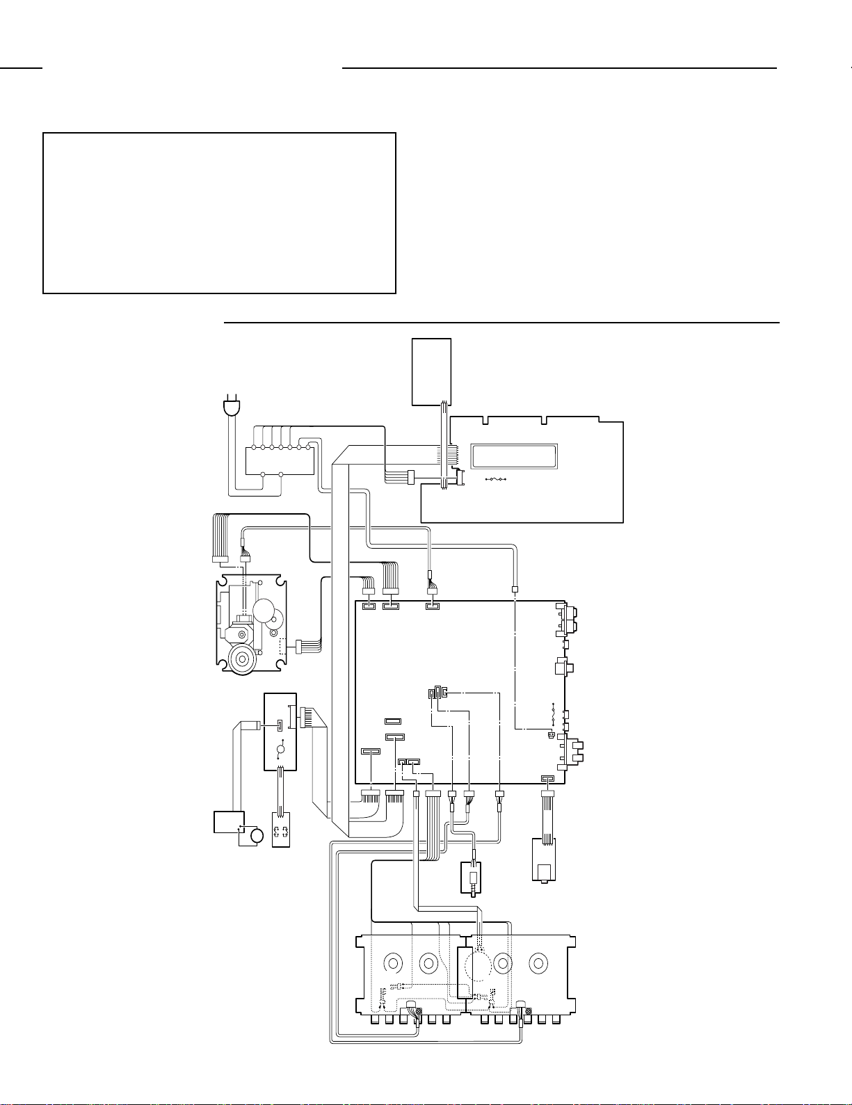
WIRING CONNECTION
AC IN
P.T
SWITCH
P.W.B
RB704
(3P)
RB705
(3P)
RB201
(10P)
CN202
(5P)
F201
DISPLAY P.W.B
3CD CHANGER
MECHANISM
INCLUDE 3CD
MECHANISM
ASSY
SENSOR P.W.B
(8P)
MOTOR P.W.B
(5P)
CN801
(10P)
M
SW P.W.B
INCLUDE 3CD
MECHANISM
ASSY
M
(6P)
RB803
(3P)
CN803
(3P)
CN803
CN802
(6P)
(5P)
CN703
(3P)
CN251
(8P)
CN201(10P)
CN804
(10P)
CN704
(2P)
BR YLYLBK GR
CN801
(5P)
CN721
CN705
(6P)
(4P)
MAIN P.W.B
CN702
(3P)
RB703
(3P)
RECORD SW
P.W.B
MECHANISM
WHRE
JK001
CN001
(2P)
JK401
F901
T3.15A
250V
CN901
(2P)
CN501
(5P)
RB501
(5P)
JK501
PHONES
PHONE
P.W.B
TAPE DECK
FM ANTENNA
75 ohm
AM LOOP
ANTENNA
L-CH SURROUND
CN502 (2P)
R-CH SURROUND
CN503 (2P)
L-CH MAIN
SPEAKER(8 ohm MIN.)
R-CH MAIN
SPEAKER(8 ohm MIN.)
SP501
MOTOR
SWITCH
R/P HEAD
- 1 -
M
RE
MOTOR
SWITCH
PLAY HEAD
Page 4
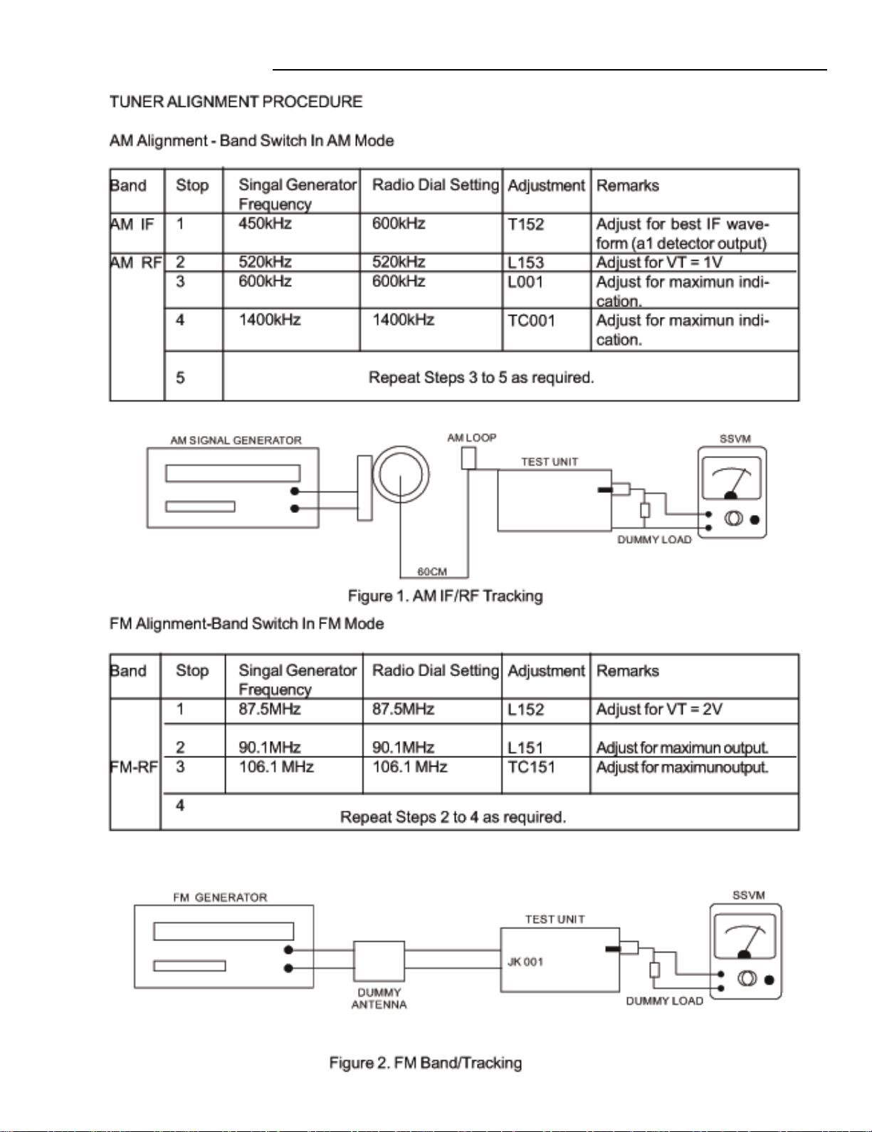
TUNER ADJUSTMENTS
- 2 -
Page 5
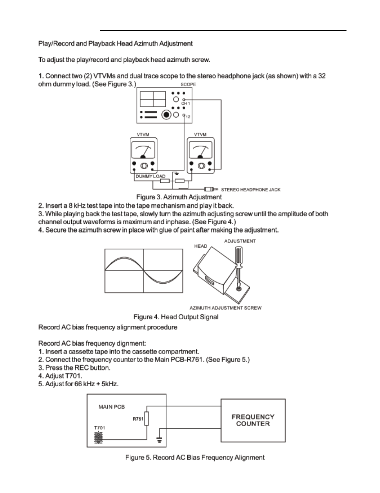
DECK ADJUSTMENTS
- 3 -
Page 6
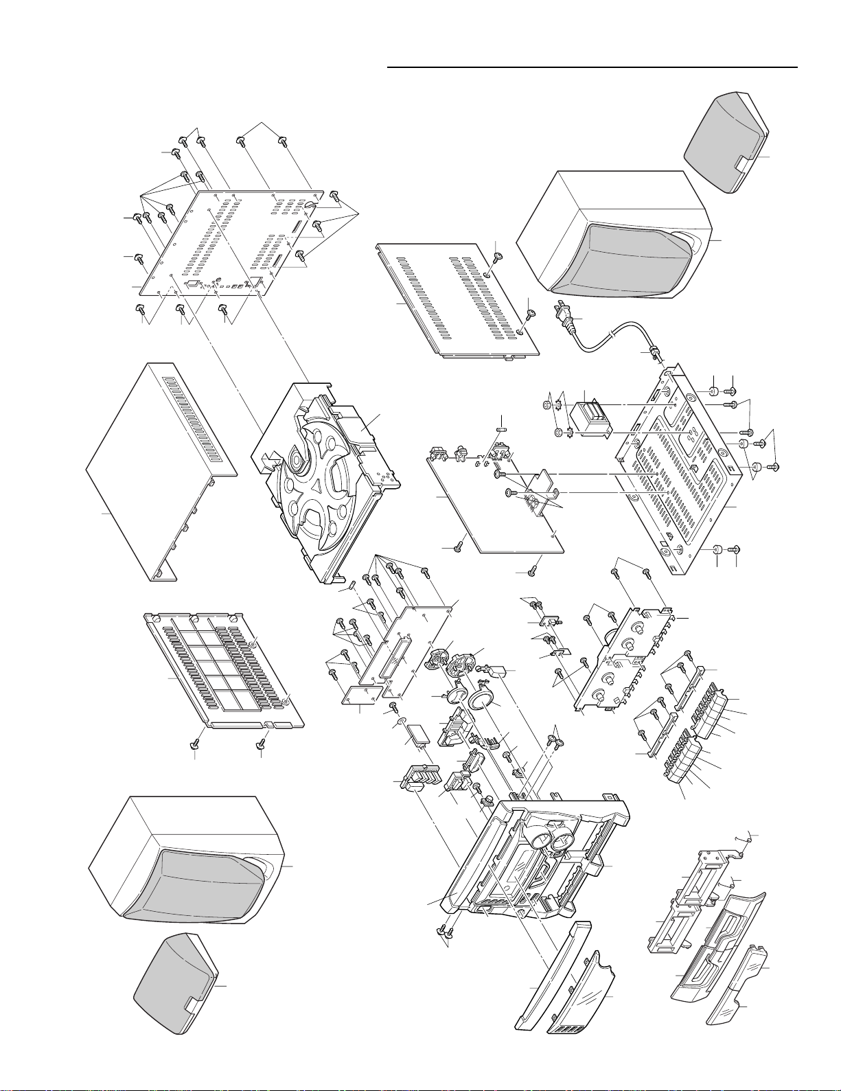
EXPLODED VIEW(CABINET & CHASSIS)
1
3
4
5
43
6
6
10
11
12
13
14
15
17
19
20
21
21
22
24
25
72
71
73
74
75
27
28
26
24
29
30
32
33
34
31
35
36
37
38
66
67
39
61
61
62
62
64
63
65
40
40
40
16
18
7
8
9
Y01
Y01
Y02
Y02
Y03
Y04
Y04
Y05
Y06
Y07
Y08
Y09
Y09
Y10
Y10 Y12
Y12
Y12
Y10
Y10
Y10
Y11
Y14
Y14
Y16
Y17
Y18
Y19
Y19
Y19
Y15
Y15
Y10
Y08
Y08
Y08
Y05
Y03
2
44
Y03
Y20
45
42
- 4 -
Page 7

PARTS LIST
PRODUCT SAFETY NOTICE
EACH PRECAUTION IN THIS MANUAL SHOULD BE FOLLOWED DURING SERVICING. COMPONENTS IDENTIFIED WITH THE
!!
!
IEC SYMBOL
OF SPECIAL SIGNIFICANCE. WHEN REPLACING A COMPONENT IDENTIFIED , USE ONLY THE REPLACEMENT PARTS
DESIGNATED, OR PARTS WITH THE SAME RATINGS OF RESISTANCE, WATTAGE OR VOLTAGE THAT ARE DESIGNATED
IN THE PARTS LIST IN THIS MANUAL. LEAKAGE-CURRENT OR RESISTANCE MEASUREMENTS MUST BE MADE TO
DETERMINE THAT EXPOSED PARTS ARE ACCEPTABLY INSULATED FROM THE SUPPLY CIRCUIT BEFORE RETURNING
THE PRODUCT TO THE CUSTOMER.
CAUTION : Regular type resistors and capacitors are not listed. To know those values, refer to the schematic diagram.
IN THE PARTS LIST AND THE SCHEMATIC DIAGRAM DESIGNATE COMPONENTS IN WHICH SAFETY CAN
Regular type resistors are less than 1/4W carbon type and 0 ohm chip resistors.
Regular type capacitors are less than 50V and less than 1000µF of Ceramic type and Electrolytic type.
PACKING & ACCESSORIES
REF.NO. PART NO. DESCRIPTION
645 048 6753 LOOP ANT ASSY,6 TURN
645 048 6760 REMOCON,RB-S300 SANYO
645 049 3621 CARTON CASE,W/O SURROUND(CA)
645 049 3638 CARTON CASE,W/O SURROUND(AU)
645 048 7712 CARTON CASE,W/SURROUND(US)
645 048 7729 POLYFOAM LEFT,MAIN LEFT
645 048 7736 POLYFOAM RIGHT,MAIN RIGHT
645 049 3645 POLYFORM TOP SPK(CA)(AU)
645 049 3652 POLYFORM BOTTOM SPK(CA)(AU)
645 048 7743 POLYFORM TOP SPK(US)
645 048 7750 POLYFORM BOTTOM SPK(US)
645 048 7774 POLYBAG,FOR PWR CORD
645 049 3669 POLYBAG,FOR I/B(CA)(AU)
645 048 7781 POLYBAG,FOR I/B(US)
645 048 7798 POLYBAG,FOR MAIN UNIT
645 048 8566 FM ANT,AWG24UL1007
645 048 8689 INSTRUCTION MANUAL(US)
645 049 3713 INSTRUCTION MANUAL(CA)
645 049 3720 INSTRUCTION MANUAL(AU)
CABINET & CHASSIS
REF.NO. PART NO. DESCRIPTION
1 645 048 7071 CASS WINDOW L
2 645 048 7088 CASS WINDOW R
3 645 048 6814 CASS DOOR L
4 645 048 6807 CASS DOOR R
5 645 048 6821 CASS BRACKET L,
CASS FRAME L TO FRONT
6 645 048 7408 CASS SPRING
7 645 048 7064 DISPLAY WINDOW,VFD
8 645 048 6845 CD DOOR,PRINT 3DISC CD CHANGER
9 645 048 6852 CABINET FRONT
10 645 048 6869 CASS KNOB REC L,NO.11
11 645 048 6876 CASS KNOB PLAY L,NO.10
12 645 048 6883 CASS KNOB REW L,NO.9
13 645 048 6890 CASS KNOB FFWD L,NO.8
14 645 048 6906 CASS KNOB STOP/EJECT,NO.7
15 645 048 6913 CASS KNOB PAUSE L,NO.6
16 645 048 6920 CASS KNOB PLAY R,NO.5
17 645 048 6937 CASS KNOB REW R,NO.4
18 645 048 6944 CASS KNOB FFWD R,NO.3
19 645 048 6951 CASS KNOB STOP/EJECT,NO.2
20 645 048 6968 CASS KNOB PAUSE R,NO.1
21 645 048 7132 BRACLET CASS KNOB,SUPPORT
22 645 048 7538 BKT REC PCB
24 645 048 7361 GEAR DAMPER,CASS FOR FRONT
25 645 048 7033 CD KNOB MULTI FUNCTI,
NO.A PWR ON,FUN,BAND,FM
26 645 048 7002 CD KNOB BASS/SOUND
27 645 048 6975 CD KNOB DISC CHANGE
28 645 048 7019 CD KNOB TUNING +/29 645 048 6982 CD KNOB DISC 123
30 645 048 7026 CD KNOB VOL
REF.NO. PART NO. DESCRIPTION
31 645 048 7040 CD KNOB PRESET
32 645 048 6999 CD KNOB OPEN/CLOSE,NO.B
33 645 048 7125 BRACKET VOL KNOB,SUPPORT
34 645 048 7118 BRACKET PRESET KNOB,
35 645 048 7095 SIDE PANEL L
36 645 048 7149 CABINET TOP
37 645 048 7477 BACK PANEL,W/SURROUND(US)
37 645 049 3607 BACK PANEL,
37 645 049 3614 BACK PANEL,
38 645 048 7101 SIDE PANEL R
39 645 048 7521 CABINET BOTTOM
40 645 048 7446 RUBBER FOOT,BOTTOM
42 645 048 6746 3CD CHANGER ASSY,
43 645 048 6838 CASS BRACKET R,
44 645 048 7057 CD WINDOWS,
61 645 048 7453 SURROUND SPK(US)
62 645 048 7460 MAIN SPK BOX(US)(AU)
62 645 049 3591 MAIN SPK BOX(CA)
67
67
!!
!
645 049 3737 LINE CORD,SAA(AU)
!!
!
645 048 9358 AC LINE CORD,
SUPPORT
W/O SURROUND(CA)
W/O SURROUND(AU)
3CD MECHA/CD DECK/ 3 PCB
CASS FRAME R TO FRONT
TOP FRONT SANYO
DB INSULATE POLARIZ(US)(CA)
FIXING PARTS
REF.NO. PART NO. DESCRIPTION
Y01 645 048 7583 SCR 3.5X14,
Y02 645 048 7675 SCR 3X8,
Y03 645 048 7675 SCR 3X8,CASS DECK TO FRONT
Y04 645 048 7606 SCR 2X4,BKT REC PCB
Y05 645 048 7651 SCR 3X10,
Y06 645 048 7569 WASHER,PHONE PCB TO FRONT
Y07 645 048 7675 SCR 3X8,PHONE JACK TO FRONT
Y08 645 048 7675 SCR 3X8,CTL PCB TO FRONT
Y09 645 048 7651 SCR 3X10,
Y10 645 048 7682 SCR 3X8,BACK TO JACK
Y11 645 048 7620 SCR 3X8,
Y12 645 048 7651 SCR 3X10,
Y14 645 048 7613 SCR 3X6,SIDE TO BOTTOM
Y15 645 048 7613 SCR 3X6,BOTTOM TO MAIN
Y16 645 048 7552 NUT,PWR TRANS
Y17 645 048 7576 WASHER,PWR TRANS
FRONT TO SPEED NUT
CASS KNOB BKT TO FRONT
GEAR DAMPER TO FRONT
BACK PANEL TO SIDE PANEL
BACK PANEL TO BOTTOM
BACK TO CD CHANGER
- 5 -
Page 8

PARTS LIST
REF.NO. PART NO. DESCRIPTION
Y18 645 048 7590 SCR 4X12,
PWR TRANS TO CAB BOTTOM
Y19 645 048 7613 SCR 3X6,BOTTOM TO FOOT
Y20 645 048 7613 SCR 3X6,
HEAT SINK TO BOTTOM
ELECTRIC-PART
REF.NO. PART NO. DESCRIPTION
63
63
64
64
65
65
66 645 048 7354 AC LINE BUSHING
!!
!
645 048 7934 FUSE,SLOW(US)(CA)
!!
!
645 049 3676 FUSE,SLOW VDE(AU)
!!
!
645 048 7941 FUSE,SLOW(US)(CA)
!!
!
645 049 3683 FUSE,SLOW(AU)
!!
!
645 048 8559 PWR TRANS,AXIAL(US)(CA)
!!
!
645 049 3706 PWR TRANS,AXIAL(AU)
645 048 9327 3P FLAT CABLE,
RB704A TO RB704B
645 048 9402 3P J WIRE AWG28 UL25,
RB203 TO J407 & J408
645 048 7163 AC CONNECTOR,
FOR PWR TRANS
645 049 3690 BEAD FERRITE,
AC CORD W/O COAT(AU)
401 089 9401 CARBON 3.3M JA 1/2W,
FOR SAFETY,PWR TRANS(CA)
645 048 9457 4P J WIRE AWG30UL 28,CN701
645 048 9433 3P J WIRE AWG30UL 25,CN702
645 048 9488 2P J WIRE,CN704
645 048 9396 6P J WIRE AWG26UL100,CN705
645 048 9440 5P J WIRE AWG30 UL 2,CN801
645 048 9365 8P J WIRE AWG30 UL10,CN802
645 048 9389 6P J WIRE AWG30 UL10,CN803
645 048 9471 10 J WIRE AWG26 UL 2,
CN804(US)
RECORD P.W.BOARD ASSY
REF.NO. PART NO. DESCRIPTION
71 614 318 3594 ASSY,PWB,RECORD SW
(Only initial)
RB703 645 048 9426 3P J WIRE AWG28UL 25,
TO MAIN CN703
SW701 645 048 8016 SW PUSH PS-22F03-BNL,
REC PLAY
PHONE P.W.BOARD ASSY
REF.NO. PART NO. DESCRIPTION
72 614 318 3587 ASSY,PWB,PHONE JACK
(Only initial)
JK501 645 048 7323 PHONE JACK
RB501 645 048 9495 5P J WIRE AWG24UL 28,
MAIN BD CN501
SWITCH P.W.BOARD ASSY
REF.NO. PART NO. DESCRIPTION
73 614 318 3570 ASSY,PWB,SWITCH(Only initial)
TA201 645 048 7965 SW TACT SKHVBE3520,PWR
TA202 645 048 7965 SW TACT SKHVBE3520,
TA203 645 048 7965 SW TACT SKHVBE3520,BAND
TA204 645 048 7965 SW TACT SKHVBE3520,
TA205 645 048 7965 SW TACT SKHVBE3520,
FUNCTION
FM MODE
MEMORY
DISPLAY P.W.BOARD ASSY
REF.NO. PART NO. DESCRIPTION
74 614 318 3563 ASSY,PWB,DISPLAY(Only initial)(US)(CA)
74 614 319 2879 ASSY,PWB,DISPLAY(Only initial)(AU)
CN203 645 048 7187 5P CONNECTOR,PWR TRANS
D0201 645 048 8085 RECTIFIER 1N4001
DP201 645 048 7910 VFD,NPN
IC201 645 048 8252 IC PT6311
LD201 645 048 7903 LED,CLASSIC
LD202 645 048 7903 LED,POPS
LD203 645 048 7903 LED,ROCK
LD204 645 048 7903 LED,JAZZ
Q0201 645 048 8122 TR 2SC945P,NPN
Q0202 645 048 8122 TR 2SC945P,NPN
Q0203 645 048 8122 TR 2SC945P,NPN
Q0204 645 048 8122 TR 2SC945P,NPN
RB201 645 048 9419 10P J WIRE,MAIN BD CN201
SN201 645 048 8382 IRT SENSOR
TA206 645 048 7965 SW TACT SKHVBE3520,BASS
TA207 645 048 7965 SW TACT SKHVBE3520,SOUND PRESET
TA208 645 048 7965 SW TACT SKHVBE3520,TUNING/TIME
TA209 645 048 7965 SW TACT SKHVBE3520,DISC CHANGE
TA210 645 048 7965 SW TACT SKHVBE3520,STOP
TA211 645 048 7965 SW TACT SKHVBE3520,PLAY/PAUSE
TA212 645 048 7965 SW TACT SKHVBE3520,TUNING/TIME DN
TA213 645 048 7965 SW TACT SKHVBE3520,DISC 1
TA214 645 048 7965 SW TACT SKHVBE3520,DISC 2
TA215 645 048 7965 SW TACT SKHVBE3520,DISC 3
TA216 645 048 7965 SW TACT SKHVBE3520,VOL DOWN
TA217 645 048 7965 SW TACT SKHVBE3520,PRESET UP
TA218 645 048 7965 SW TACT SKHVBE3520,PRESET DOWN
TA219 645 048 7965 SW TACT SKHVBE3520,OPEN/CLOSE
TA220 645 048 7965 SW TACT SKHVBE3520,VOL UP
ZD201 645 048 8207 ZENER DIODE 5.6V
645 048 7309 FUSE CLIP,FOR F201(AU)
645 048 7378 SLEEVING SILICON TUB,FOR R222X2 ,
R223X2(AU)
645 048 7545 BRACKET,FOR VFD(AU)
645 048 7767 SPONGE,FOR IR SENSOR(AU)
645 048 7309 FUSE CLIP,FOR F201(US)(CA)
645 048 7545 BRACKET,FOR VFD(US)(CA)
645 048 7767 SPONGE,FOR IR SENSOR(US)(CA)
MAIN P.W.BOARD ASSY
REF.NO. PART NO. DESCRIPTION
75 614 318 3556 ASSY,PWB,MAIN(Only initial)(US)
75 614 319 2862 ASSY,PWB,MAIN(Only initial)(CA)
75 614 319 3074 ASSY,PWB,MAIN(Only initial)(AU)
C0153 645 048 8054 POLYESTER 560PF
C0177 403 058 2406 POLYESTER 0.015U J 50V
C0178 403 058 2406 POLYESTER 0.015U J 50V
C0179 403 058 7401 POLYESTER 1800P J 50V
C0180 403 058 7401 POLYESTER 1800P J 50V
C0181 403 058 7401 POLYESTER 1800P J 50V
C0182 403 058 7401 POLYESTER 1800P J 50V
C0186 403 060 5204 POLYESTER 3300P J 50V
C0252 403 135 4507 ELECT 1000U M 10V
C0411 403 057 1905 POLYESTER 0.1U J 50V
C0412 403 057 1905 POLYESTER 0.1U J 50V
C0413 403 057 1905 POLYESTER 0.1U J 50V
C0414 403 057 1905 POLYESTER 0.1U J 50V
C0415 403 062 4403 POLYESTER 5600P J 50V
C0416 403 062 4403 POLYESTER 5600P J 50V
C0511 403 058 4608 POLYESTER 0.15U J 50V
C0512 403 058 4608 POLYESTER 0.15U J 50V
C0513 403 125 5507 ELECT 1000U M 16V
C0514 403 125 5507 ELECT 1000U M 16V
C0701 403 059 9800 POLYESTER 2700P J 50V
C0702 403 059 9800 POLYESTER 2700P J 50V
- 6 -
Page 9

PARTS LIST
REF.NO. PART NO. DESCRIPTION REF.NO. PART NO. DESCRIPTION
C0703 403 058 0303 POLYESTER 1500P J 50V
C0704 403 058 0303 POLYESTER 1500P J 50V
C0707 403 058 9108 POLYESTER 0.018U J 50V
C0708 403 058 9108 POLYESTER 0.018U J 50V
C0721 403 056 7106 POLYESTER 1000P J 50V
C0722 403 056 7106 POLYESTER 1000P J 50V
C0735 403 058 7401 POLYESTER 1800P J 50V
C0738 403 057 6801 POLYESTER 0.012U J 50V
C0739 403 060 7406 POLYESTER 0.033U J 50V
C0747 403 056 7106 POLYESTER 1000P J 50V
C0748 403 056 7106 POLYESTER 1000P J 50V
C0749 403 058 0303 POLYESTER 1500P J 50V
C0750 403 058 0303 POLYESTER 1500P J 50V
C0754 403 062 4403 POLYESTER 5600P J 50V
C0767 403 056 7106 POLYESTER 1000P J 50V
C0768 403 056 7106 POLYESTER 1000P J 50V
C0771 403 057 5101 POLYESTER 1200P J 50V
C0772 403 057 5101 POLYESTER 1200P J 50V
C0811 403 062 9101 POLYESTER 6800P J 50V
C0812 403 061 7306 POLYESTER 4700P J 50V
C0818 403 059 9800 POLYESTER 2700P J 50V
CF151 645 048 7828 CERAMIC FILTER 450KH,SFU450B
CF152 645 048 7842 CERAMIC FILTER 10.7M,SFE-10.7M A
CF153 645 048 7835 CERAMIC FILTER 10.7M,SFE-10.7MS2-A
CF154 645 048 7880 CERAMIC FILTER 10.7M,CDA10.7MG-80A
CN001 645 048 7224 2P CONNECTOR,AM LOOP ANT
CN201 645 048 7293 10P CONNECTOR,DISPLAY RB201
CN251 645 048 7286 8P CONNECTOR
CN501 645 048 7200 5P CONNECTOR,PHONE BD RB501
CN502 645 048 7224 2P CONNECTOR,SURROUND SPK(US)
CN503 645 048 7224 2P CONNECTOR,SURROUND SPK(US)
CN701 645 048 7194 4P CONNECTOR,CASS DECK B RB701
CN702 645 048 7217 3P CONNECTOR,CASS DECK A RB702
CN703 645 048 7255 3P CONNECTOR,SW BD RB703
CN704 645 048 7248 2P CONNECTOR,CASS MOTOR
CN705 645 048 7279 6P CONNECTOR,CASS DECK PLAY/MR
CN801 645 048 7262 5P CONNECTOR,TO CDM
CN802 645 048 7286 8P CONNECTOR,TO CDM
CN803 645 048 7279 6P CONNECTOR,TO CDM
CN804 645 048 7293 10P CONNECTOR,TO CDM
CN901 645 048 7231 2P CONNECTOR,PWR TRANS
D0001 645 048 8092 DIODE 1N4148
D0002 645 048 8092 DIODE 1N4148
D0152 645 048 8092 DIODE 1N4148
D0153 645 048 8092 DIODE 1N4148
D0251 645 048 8092 DIODE 1N4148
D0252 645 048 8092 DIODE 1N4148
D0253 645 048 8092 DIODE 1N4148
D0401 645 048 8092 DIODE 1N4148
D0501 645 048 8092 DIODE 1N4148
D0701 645 048 8092 DIODE 1N4148
D0705 645 048 8092 DIODE 1N4148
D0710 645 048 8092 DIODE 1N4148
D0711 645 048 8092 DIODE 1N4148
D0801 645 048 8092 DIODE 1N4148
D0802 645 048 8092 DIODE 1N4148
D0901 645 048 8108 RECTIFIER 1N5392
D0902 645 048 8108 RECTIFIER 1N5392
D0903 645 048 8108 RECTIFIER 1N5392
D0904 645 048 8108 RECTIFIER 1N5392
D0905 645 048 8092 DIODE 1N4148
IC151 645 048 8306 IC TA2104BN,
DIGITAL TUNING SYS
IC202 645 048 8238 IC 5V43-1 J15,
M-CU TMP87EP26 (SHIBATEC)
IC203 645 048 8276 IC TC9257F
IC401 645 048 8269 IC TDA7440D,VOL TONE CTL
IC402 645 048 8313 IC JRC4558D,OP AMP DIP
IC501 645 048 8351 IC TA8227P
IC701 645 048 8344 IC TA8189N,
DUAL R/P DECK PRE AMP
IC801 645 048 8245 IC TA2109F,
RF AMP DIGITALSERV CD
IC802 645 048 8290 IC TC9462F,
DIGITAL SERVO SINGLE
IC803 645 048 8283 IC KA9258D,PWR DRIVE IC
IC804 645 048 8320 IC TA7291S
IC805 645 048 8320 IC TA7291S
IC902 645 048 8337 IC AN7806
JK001 645 048 7316 ANT JACK,FM ANT
JK401 645 048 7347 RCA JACK,VIDEO IN
L0001 645 048 8504 AM ANT OSC,
COILS:R2523-0A10
L0002 645 048 8528 CHOKE COIL 22MH
L0151 645 048 8474 RF COIL
L0152 645 048 8498 OSC COIL
L0153 645 048 8511 AM OSC
L0154 645 048 8467 RF COIL
L0155 645 048 8443 CHOKE COIL 39UH
L0156 645 048 8443 CHOKE COIL 39UH
L0157 645 048 8467 RF COIL
L0251 645 048 8429 CHOKE COIL 10UH
L0252 645 048 8429 CHOKE COIL 10UH
L0253 645 048 8436 CHOKE COIL 100UH
L0701 645 048 8528 CHOKE COIL 22MH
L0702 645 048 8528 CHOKE COIL 22MH
L0703 645 048 8528 CHOKE COIL 22MH
L0704 645 048 8528 CHOKE COIL 22MH
L0801 645 048 8436 CHOKE COIL 100UH
L0802 645 048 8436 CHOKE COIL 100UH
L0803 645 048 8436 CHOKE COIL 100UH
Q0001 645 048 8115 TR 2SK192A-Y GR,FET
Q0151 645 048 8122 TR 2SC945P,NPN
Q0152 645 048 8122 TR 2SC945P,NPN
Q0153 645 048 8122 TR 2SC945P,NPN
Q0154 645 048 8122 TR 2SC945P,NPN
Q0155 645 048 8122 TR 2SC945P,NPN
Q0157 645 048 8139 TR 2SC1675L,NPN
Q0158 645 048 8122 TR 2SC945P,NPN
Q0159 645 048 8122 TR 2SC945P,NPN
Q0160 645 048 8122 TR 2SC945P,NPN
Q0251 645 048 8139 TR 2SC1675L,NPN
Q0252 645 048 8122 TR 2SC945P,NPN
Q0253 645 048 8153 TR 2SA733Q P,PNP
Q0254 645 048 8122 TR 2SC945P,NPN
Q0255 645 048 8139 TR 2SC1675L,NPN
Q0501 645 048 8146 TR 2SC2878-A,NPN
Q0502 645 048 8146 TR 2SC2878-A,NPN
Q0503 645 048 8122 TR 2SC945P,NPN
Q0504 645 048 8122 TR 2SC945P,NPN
Q0701 645 048 8122 TR 2SC945P,NPN
Q0702 645 048 8122 TR 2SC945P,NPN
Q0703 645 048 8122 TR 2SC945P,NPN
Q0704 645 048 8122 TR 2SC945P,NPN
Q0705 645 048 8122 TR 2SC945P,NPN
Q0707 645 048 8160 TR 2SA952,PNP
Q0708 645 048 8122 TR 2SC945P,NPN
Q0709 645 048 8122 TR 2SC945P,NPN
Q0711 645 048 8122 TR 2SC945P,NPN
Q0713 645 048 8122 TR 2SC945P,NPN
Q0714 645 048 8122 TR 2SC945P,NPN
Q0801 645 048 8160 TR 2SA952,PNP
Q0802 645 048 8122 TR 2SC945P,NPN
Q0803 645 048 8122 TR 2SC945P,NPN
Q0804 645 048 8160 TR 2SA952,PNP
Q0805 645 048 8122 TR 2SC945P,NPN
- 7 -
Page 10

PARTS LIST
REF.NO. PART NO. DESCRIPTION
Q0901 645 048 8153 TR 2SA733Q P,PNP
Q0902 645 048 8122 TR 2SC945P,NPN
Q0903 645 048 8368 TR TIP41C,NPN
Q0904 645 048 8122 TR 2SC945P,NPN
Q0905 645 048 8153 TR 2SA733Q P,PNP
Q0906 645 048 8375 TR 2SD882P,NPN
R0846 401 010 1306 CARBON 4.7 JA 1/2W(CA)(AU)
R0908 401 006 9903 CARBON 100 JA 1/2W
(CA)(AU)
SP501 645 048 7330 SPK JACK,L/R SPK
SW501 645 048 8009 SW SLIDE,
PCB TYPE SS-12F23(US)
SW702 645 048 8009 SW SLIDE,
PCB TYPE SS-12F23
T0152 645 048 8450 AM IFT
T0701 645 048 8481 OSC COIL,REC OSC
TA221 645 048 8023 SW TACT,
RADIAL TYPE BGT0235 RESE
TC001 645 048 7989 TRIMMER 20PF,N450
TC151 645 048 7972 TRIMMER 10PF,NP0
VD001 645 048 8405 DIODE 1SV149B,
AM TUNING DIODE
VD151 645 048 8412 DIODE 1SV101,
FM TUNING DIODE
VD152 645 048 8412 DIODE 1SV101,
FM TUNING DIODE
VD153 645 048 8405 DIODE 1SV149B,
AM TUNING DIODE
XL201 645 048 7897 RESONATOR 4.5MHZ,
CSA4.5MTZ
XL202 645 048 7859 CRYSTAL 32.768KHZ,C-001R
XL203 645 048 7873 CRYSTAL 7.2MHZ,HC-49/U
XL801 645 048 7866 CRYSTAL 16.9344MHZ,
HC-49/U
ZD151 645 048 8177 ZENER DIODE 3.9V
ZD251 645 048 8184 ZENER DIODE 4.6V
REF.NO. PART NO. DESCRIPTION
ZD801 645 048 8191 ZENER DIODE 5.1V
ZD901 645 048 8214 ZENER DIODE 9.1V
ZD902 645 048 8214 ZENER DIODE 9.1V
ZD903 645 048 8221 ZENER DIODE 12V
645 048 7309 FUSE CLIP,FOR FUSE
(CA)(AU)
645 048 7675 SCR 3X8,MAIN TO HEAT SINK
(US)
645 048 7392 WASHER,FOR Q903(CA)(AU)
645 048 7491 HEAT SINK,MAIN TO BOTTOM
(CA)
645 048 7491 HEAT SINK,MAIN TO BOTTOM
(AU)
645 048 7507 HEAT SINK,FOR IC501
(CA)(AU)
645 048 7514 MICA SHEET,
FOR Q903/Q906 W/1 HOLE
(CA)(AU)
645 048 7675 SCR 3X8,IC TO HEAT SINK
(CA)(AU)
645 048 7675 SCR 3X8,MAIN TO HEAT SINK
(CA)(AU)
645 048 7804 SPONGE,FOR L151/152
(CA)(AU)
645 048 7309 FUSE CLIP,FOR FUSE(US)
645 048 7378 SLEEVING SILICON TUB,
FOR D901-904 X2(US)
645 048 7392 WASHER,FOR Q903(US)
645 048 7491 HEAT SINK,MAIN TO BOTTOM
(US)
645 048 7507 HEAT SINK,FOR IC501(US)
645 048 7514 MICA SHEET,
FOR Q903/Q906 W/1 HOLE
(US)
645 048 7675 SCR 3X8,IC TO HEAT SINK(US)
645 048 7804 SPONGE,FOR L151/152(US)
IC BLOCK DIAGRAM & DESCRIPTION
IC802 TC9462F(Digaital Servo Signal)
- 8 -
Page 11

EXPLODED VIEW(TAPE DECK)
TM01
TM02
TM04
TM03
TM04
TM05
TM06
TM05
PARTS LIST
M1 MECHANISM CHASSIS
REF.NO. PART NO. DESCRIPTION
45 645 048 8573 CASS MECHANISM,SEMI AUTOSTOP
TM01 645 030 6839 E HEAD
TM02 645 041 3025 R.P HEAD
TM03 645 048 7927 B/P HEAD
TM04 645 048 8740 PINCH ROLLER ARM
TM05 645 048 9235 R F BELT
TM06 645 048 9228 MAIN BELT
TM07 645 048 7958 MOTOR ASSY
TM06
TM07
- 9 -
Page 12

IC BLOCK DIAGRAM & DESCRIPTION
IC803 KA9258D(Power drive)
IC201 PT6311(Display Memory)
IC301 KIA4558F(Ope.AMP)
OUT A
-IN A
+IN A
V
EE
1
A
2
-
+
3
4
B
-
+
8
7
6
5
CC
V
OUT B
-IN B
+IN B
IC801 TA2109F(RF AMP. Digital Servo)
IC151 TA21048D(Digital tuning)
- 10 -
Page 13

IC BLOCK DIAGRAM & DESCRIPTION
IC401 TDA7440D(VOL. TONE CTL.)
IC701 TA8189 (Dual R/P Deck Pre AMP)
IC804,805 TA7291S (Bridge Driver)
Vcc
Vref
2
8
REG
Protective Circuit
(Heat Interception)
1
9
IN1
IN2
5
GND
IC203 TC9257F(Shift Register)
IC501 TA8227/8227P(4 CHANNEL MULUTI DEM)
Vs
6
OUT1
7
3
OUT2
- 11 -
Page 14

IC & TRANSISTOR VOLTAGES
IC202 TMP87EP26
Pin No. 12345678910111213141516
ON 0 2.6 2.6 5.2 2.5 1.9 0 0 5.2 5.1 4.3 2.2 3.4 5.3 5.2 0
OFF 0 2.6 2.6 5.2 2.5 1.9 0 0 5.2 5.1 4.3 2.2 3.4 5.3 5.2 0
Pin No. 17 18 19 20 21 22 23 24 25 26 27 28 29 30 31 32
ON 05.305.35.305.25.205.05.000000
OFF 05.305.35.305.25.205.01.72.20000
Pin No. 33 34 35 36 37 38 39 40 41 42 43 44 45 46 47 48
ON 00000005.25.20.94.45.35.25.25.25.2
OFF 00000005.25.20.94.45.35.25.25.25.2
Pin No. 49 50 51 52 53 54 55 56 57 58 59 60 61 62 63 64
ON 005.30000000000000
OFF 005.30000000000000
Pin No. 65 66 67 68 69 70 71 72 73 74 75 76 77 78 79 80
ON 0000000000000000
OFF 0000000000000000
Pin No. 81 82 83 84 85 86 87 88 89 90 91 92 93 94 95 96
ON 0000000000000000
OFF 0000000000000000
Pin No. 97 98 99 100
ON 0 5.2 5.2 5.3
OFF 0 5.2 5.2 5.3
IC501 TA8227
Pin No. 123456789101112
ON 13.5 7.1 13.3 0 0.6 0 0 0.6 7.2 13.3 7.1 14.8
OFF 0.6 0.4 0.6 0 0.4 0 0 0.4 0.6 0.6 0.4 15.5
(V)
(V)
IC401 TDA7440D
Pin No. 12345678910111213141516
Voltage 3.9 3.9 3.9 3.9 3.9 3.9 3.9 3.9 3.9 3.9 3.9 3.9 3.9 3.9 3.9 0
Pin No. 17 18 19 20 21 22 23 24 25 26 27 28
Voltage 0 3.9 3.6 0 5.3 5.3 3.9 7.8 0 3.2 3.2 3.9
IC151 TA2104BN
Pin No. 12345678910111213141516
AM 0 0 1 4.4 4.4 3.7 4.4 0 0.1 3.8 1.2 1.2 0 0 0.7 1.1
FM 0 0.8 0 4.2 4.4 3.8 4.4 0 0.4 3.8 1.2 1.2 3.5 0 0.7 1.2
STOP 0 0.8 0 4.2 4. 4 3.8 4.4 0 0.4 3.8 1.2 1.2 3.7 3.6 0.7 1.2
Pin No. 17 18 19 20 21 22 23 24
AM 0.9 4.4 4.4 4.4 4.4 4.4 0 4.4
FM 0.7 4.4 4.4 4.4 4.4 4.4 0 4.4
STOP 0.7 0 4.4 4.4 4.4 4.4 0 4.4
IC203 TC9257F
Pin No. 12345678910111213141516
AM 2.4 2.4 5.2 5.2 0 0.3 4.9 0.3 0.3 4.9 0 4.9 2.5 0.1 0 2.4
FM 2.4 2.4 5.2 5.2 0 0.3 4.9 0.3 0.3 4.9 0 4.9 0 2.4 0 2.4
CD 0.23.45.25.200.30.43.90.300502.402.4
TAPE 0. 2 3.4 5.2 5.2 0 0.3 0.4 0.3 0.3 00500.100
VD 0.23.45.25.200.30.40.3500500.100
STOP 2.4 2.4 5.2 5.2 0 0.3 4.9 0.3 0.3 0 0 4.9 0 0.1 0 0
Pin No. 17 18 19 20
AM 0 0 0.4 1.1
FM 4.9 0 0.7 1.1
CD 4.9 0 0.7 1.1 123
TAPE 0 0 0 1.1 15. 5 0 60
VD 0001.1
STOP 0 0 0 1. 1
IC902 AN7806
Pin No.
Voltage
(V)
(V)
(V)
(V)
- 12 -
Page 15

IC & TRANSISTOR VOLTAGES
S
S
IC701 TA8189N
Pin No. 12345678910111213141516
REC 0 1.6 1.3 1.2 1.3 1.3 0 0 2.4 1.3 0 0 0.9 0 1.3 2.4
PLAY 0 0 1.3 1.3 1.3 1.3 0 0 2.4 1.3 0 0 0.9 0 1.3 2.4
Pin No. 17 1 8 19 20 2 1 22 23 2 4
REC 1.5 9.5 A:1.0 1.3 1.3 1.3 1.6 0
PLAY 1.5 9.5 B:0.6 1.3 1.3 1.3 0 0
IC801 TA2109
Pin No. 12345678910111213141516
PLAY 4.9 2.1 2.1 2.1 2.1 0.2 3.8 2.4 2.3 4.1 2.1 2.1 2.7 2.1 2.1 2.1
STOP 4.9 2.1 2.1 0 0 0 4.3 0 2.3 4.2 2. 1 2.1 1 2.1 2.1 2.1
Pin No. 17 1 8 19 20 2 1 22 23 2 4
PLAY 3.3 2.1 2 3.3 2.1 1.8 0 2.1
STOP 1.1 2.1 2 3.3 2.1 1.1 0 2.1
IC803 KA9258D
Pin No. 12345678910111213141516
PLAY 3.4 4 2.1 2.1 7.8 5.1 5.1 0 2.1 4.1 3.4 0 0 7.8 2.1 2.7
STOP 3.9 3.9 2.1 2.1 7.9 5.1 5.1 0 2.1 3.9 3.9 0 0 8 2.1 2.7
Pin No. 17 1 8 19 20 2 1 22 23 2 4 25 26 2 7 28
PLAY 3.8 3.8 2.1 2.1 8.2 8.2 2.1 2.1 2.1 3.8 3.7 0
STOP 3.9 3.9 2.1 2.1 8.5 8.5 2.1 2.1 2.1 3.9 3.8 0
IC802 TC9062
Pin No. 12345678910111213141516
PLAY 5.1 5.1 5.1 0 2.7 0 2.6 0 5.1 0 5.1 5 0.1 5.1 0 0.1
STOP 5.1 5.1 5.1 0 2.7 0 2.6 0 5.1 0.4 5.1 0 0. 1 5.1 0 0
Pin No. 17 1 8 19 20 2 1 22 23 2 4 25 26 2 7 28 29 3 0 31 32
PLAY 2.4 0.1 3.1 0.6 1.7 0 5.1 0 4.1 2.1 0 2.1 2.1 2.1 2.1 2.1
STOP 2.4 0 3.1 2.5 1.7 5.1 5.1 0 4.2 2.1 5.1 2.1 2. 1 0 0 4.3
Pin No. 33 3 4 35 36 3 7 38 39 4 0 41 42 4 3 44 45 4 6 47 48
PLAY 2.1 2.1 1.4 0 2.1 2.1 5.1 2.1 2.1 3.3 2.1 2.6 2.1 2.1 2.1 2.1
STOP 2.1 2.1 1.4 0 2 2. 1 2.1 2.1 1.1 2.1 1.1 2.1 2.1 2.1 2. 1 2.1
Pin No. 49 5 0 51 52 5 3 54 55 5 6 57 58 5 9 60 61 6 2 63 64
PLAY 2.1 2.1 3.2 2.3 2.1 2.1 2.2 4.1 2.4 0 5.1 0 0 5.1 0 0
STOP 2.1 2.1 3.4 2.4 2.1 2.1 2.1 4.2 0 5.1 5.1 5.1 5. 1 5.1 0 0
Pin No. 65 6 6 67 68 6 9 70 71 7 2 73 74 7 5 76 77 7 8 79 80
PLAY 0 0 0 5.1 5.1 5.1 00005.15.102.12.45.1
STOP 0 0 0 5. 1 5.1 5.1 00005.15.102.12.45.1
Pin No. 81 8 2 83 84 8 5 86 87 8 8 89 90 9 1 92 93 9 4 95 96
PLAY 0 2.7 5.1 2.6 2.7 0 5.1 5.1 5.1 4.8 4.8 4.8 4.7 5.1 0 4.6
STOP 0 2.7 5.1 2.5 2. 7 0 5.1 5.1 5.1 5.1 5.1 5.1 5.1 5.1 0 5.1
Pin No. 97 9 8 99 100
PLAY 4.1 5.1 5.1 5.1
STOP 5.1 5.1 5.1 5.1
(V)
(V)
(V)
(V)
IC805 TA7291
Pin No. 123456789
VOLTAGE 11.5 000011.5 0 5.2 0
IC804 TA7291
Pin No. 123456789
VOLTAGE 11.5 000011.5 0 0.8 0
(V)
(V)
IC201 PT6311
Pin No. 12345678910111213141516
PLAY 000003.304.32.2000000Hight
Pin No. 17 1 8 19 20 2 1 22 23 2 4 25 26 2 7 28 29 3 0 31 32
PLAY Hight Hight Hight Hight Hight Hight Hight Hight Hight Hight Hight Hight Hight Hight Hight Hight
Pin No. 33 3 4 35 36 3 7 38 39 4 0 41 42 4 3 44 45 4 6 47 48
PLAY 5.1 -2.3 Hight Hight Hight Hight Hight Hight Hight Hight Hight Hight 5. 1 0 0 0
Pin No. 49 5 0 51 52
PLAY 0 5 0 2.7
- 13 -
(V)
Page 16

SCHEMATIC DIAGRAM(MAIN for US)
This is a basic schematic diagram.
- 14 -
PRODUCT SAFETY NOTICE
Each precaution in this manual should be followed during servicing. Components identified with the IEC symbol
list and the schematic diagram designated components in which safety can be of special significance. When replacing a component
identified by
are designated in the parts list in this manual. Leakage-current or resistance measurements must be made to determine that
exposed parts are acceptably insulated from the supply circuit before returning the product to the customer.
!!
!
, use only the replacement parts designated, or parts with the same ratings of resistance, wattage or voltage that
in the parts
!!
!
- 15 -
Page 17

SCHEMATIC DIAGRAM(MAIN for CA)
This is a basic schematic diagram.
- 16 -
PRODUCT SAFETY NOTICE
Each precaution in this manual should be followed during servicing. Components identified with the IEC symbol
list and the schematic diagram designated components in which safety can be of special significance. When replacing a component
identified by
are designated in the parts list in this manual. Leakage-current or resistance measurements must be made to determine that
exposed parts are acceptably insulated from the supply circuit before returning the product to the customer.
!!
!
, use only the replacement parts designated, or parts with the same ratings of resistance, wattage or voltage that
in the parts
!!
!
- 17 -
Page 18

SCHEMATIC DIAGRAM(MAIN for AU)
This is a basic schematic diagram.
- 18 -
PRODUCT SAFETY NOTICE
Each precaution in this manual should be followed during servicing. Components identified with the IEC symbol
list and the schematic diagram designated components in which safety can be of special significance. When replacing a component
identified by
are designated in the parts list in this manual. Leakage-current or resistance measurements must be made to determine that
exposed parts are acceptably insulated from the supply circuit before returning the product to the customer.
!!
!
, use only the replacement parts designated, or parts with the same ratings of resistance, wattage or voltage that
in the parts
!!
!
- 19 -
Page 19

SCHEMATIC DIAGRAM(CD MAIN)
This is a basic schematic diagram.
- 20 -
- 21 -
Page 20

WIRING DIAGRAM (DISPLAY)WIRING DIAGRAM (MAIN)
- 22 -
- 23 -
Page 21

WIRING DIAGRAM (RECORD SW & SWITCH and PHONE )
RECORD SW
SWITCH
PHONE JACK
- 24 -
 Loading...