

Page 1
Please read all instructions below and install this system properly.
Please read "SAFETY PRECAUTIONS" and "IMPORTANT SAFETY INSTRUCTIONS" on
OWNER'S MANUAL to install and place this system.
This system is supplied in 3 packages and they need to be installed. Please make sure all the
parts are included. If any part is missing, or if you have questions, contact a sales dealer.
CAUTION
WHEN INSTALLING THIS SYSTEM, BE CAREFUL NOT TO DAMAGE THE PROJECTION
SCREEN. AND NEVER TOUCH THE SURFACE OF THE PROJECTION SCREEN AND
THE PROJECTION MIRROR DIRECTLY. THEY MAY EFFECT THE PROJECTION IMAGE
QUALITY.
BE CAREFUL NOT TO DROP ANY PART OR TOOL LIKE SCREW INTO THE SYSTEM. IF
IT SHOULD, CONTACT A SERVICE.
EXCEPT WHEN ADJUSTING THE PROJECTION MIRROR, NEVER TURN THE SYSTEM
ON UNTIL THE INSTALLATION IS FINISHED. IT MAY CAUSE ELECTRICAL SHOCK OR
FIRE HAZARD.
REQUEST A SALES DEALER FOR INST ALLATION
Rear Projection Display
Installation Manual
Install the system following steps.
1AA6P1P1756-- (M8EA)
1.
CHECK CONTENTS IN PACKAGES
2.
ASSEMBLE BOTTOM CABINET
3.
JOINT TOP AND BOTTOM CABINETS
4.
SETUP PROJECTION MIRROR
5.
ADJUST PROJECTION MIRROR
THIS SYSTEM MUST BE INST ALLED BY 2 OR MORE PEOPLE
6.
ASSEMBLE STORAGE SPACES
7.
LOCK CABINET
710-00792-1
Page 2
1
CHECK CONTENTS IN PA CKAGES
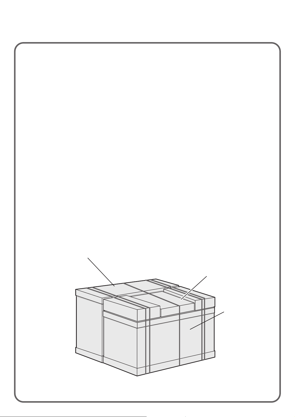
This system is supplied in 3 packages. Make sure all the parts listed below (cabinets, Installation parts,
and accessories) are included in those packages.
Top Cabinet : Refer to the steps 3 to 6 for installation.
Center Panel ----------------------------------------- 1
Package 1
Package 2
Package 3
Bottom Cabinet : Refer to the steps 2, 6 and 7 for installation.
Installation Part
Owner's Manual ---------------------------------------1
Installation Manual (this brochure) --------------- *
AC Power Cord ---------------------------------------*
Wireless Remote Control Unit -------------------- 1
Wireless/Wired Remote Control Unit -----------1
Remote Control Cable ----------------------------- 1
Batteries for Remote Controls -------------------- 4
VGA Cable ------------------------------------------- 1
MAC/VGA Adapter ---------------------------------- 1
Mouse Cables (Serial, PS/2, ADB)--------------- *
The accessories marked (*) may not supplied or may be
differ in quantity in some models. Refer to the Owner's
Manual for details.
Accessories
Qty.
Glass Doors ------------------------------------------- 2
Compartment Shelves ----------------------------- 4
Shelves' Pins ----------------------------------------- 16
Installation Parts
Qty.
Package 1
Package 2
Package 3
u Actual packages may be differ from this figure in some models.
Page 3
2
ASSEMBLE BOTTOM CABINET
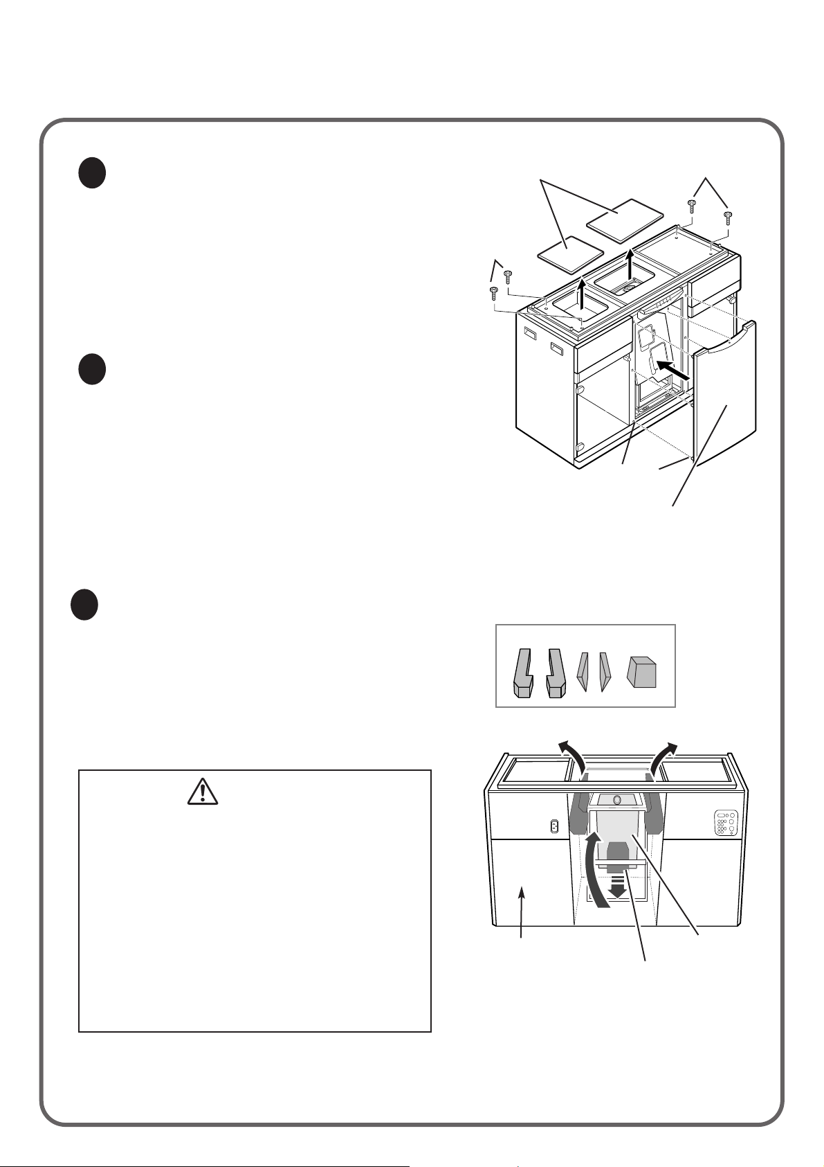
Remove the 4 Joint Bolts on the Bottom Cabinet.
Keep these bolts for later use. They are necessary
for joint the Top and Bottom Cabinets.
Remove the 2 Cover Plates on the top of the
Bottom Cabinet. Keep the Cover Plates for later
use. Replace those plates, when the appliance
needs to be transported.
Install the Center Panel to the Bottom Cabinet. Be
sure to meet the Center Panel and the Bottom
Cabinet at the upper part first, and insert the 6 legs
of Center Panel to the holes of the Bottom Cabinet.
Be sure to set the Center Panel securely.
Remove Joint Bolts and Cover Plates
Install Center Panel
1
2
Cover Plates
(2 pcs)
Joint Bolts (4 pcs)
Center Panel
Meet the Center Panel and the Bottom
Cabinet at the upper part first and
push in the Panel securely.
LegHole
There are the 5 Protection Pads inside of the
Bottom Cabinet for protection against shock or
vibration. Remove the 4 Pads supporting at the
upper side of the Bottom Cabinet first. And then,
remove the pad(A) supporting at the lower side of
the projector. When removing the pad(A), pull
downward first and remove the pad.
Remove Protection Pads
3
CAUTION
WHEN REMOVING THE PROTECTION
PADS, BE CAREFUL NOT TO BROKE THE
WIRING INSIDE OF THE BOTTOM
CABINET.
BE SURE TO REMOVE ALL THE
PROTECTION PADS INSIDE OF THE
CABINET. AND BE CAREFUL NOT TO
LEAVE ANY PAD OR FRAGMENT IN THE
CABINET. IT MAY RESULT IN FIRE
HAZARDS.
Joint Bolts
(4 pcs)
Protection Pads (5 pcs)
The back side of
the Bottom Cabinet.
Pad(A)
Pull the pad(A) to
downward first and
remove the pad.
Projector
Page 4

,,,
,,,
3
J0INT T OP AND BOTT OM CABINETS
Lift the Top Cabinet and put it on the Bottom
Cabinet. When setting the Top Cabinet, be sure
the frame of the Bottom Cabinet is fitted into the
frame of the Top Cabinet completely.
Remove the 14 Screws and the Back Cover. Keep
the screws and Back Cover. All the installations are
finished, all those parts should be replaced.
Remove the Cover Plate on the lower part of the
Top Cabinet. Keep the Cover Plate for later use.
Replace this plate when the appliance need to be
transported.
Joint Top and Bottom Cabinets
Remove Back Cover
Remove Cover Plate
1
2
3
Joint the Top and the Bottom Cabinets with the 4
Joint Bolts securely.
Fix the Cabinets
4
CAUTION
BE SURE TO FIX THE CABINETS WITH
JOINT BOLTS. IF THE TOP AND THE
BOTTOM CABINETS ARE NOT FIXED
PROPERLY, THE TOP CABINET MAY
BE DROPPED OR FALL DOWN.
Screws (14 pcs)
Bottom
Cabinet
Top
Cabinet
Be sure the frame of
the Bottom Cabinet
is fitted into the
frame of the Top
Cabinet completely.
Bottom
Cabinet
Top
Cabinet
Joint Bolts
(4 pcs)
Joint Bolts
(4 pcs)
Cover Plate
Frame
CAUTION
THE TOP CABINET OF THIS PROJECTOR
HAS ITS GRAVITY AT THE SCREEN SIDE.
WHEN LIFTING THE TOP CABINET, BE
CAREFUL NOT TO DROP.
Page 5

4
SETUP PROJECTION MIRROR
Remove the 4 Protection Pads inside of the Top
Cabinet and remove the 2 Fixing Bands (right and
left) of the Projection Mirror.
Remove the 8 Screws(A) of the Mirror Arms. Lift
the Projection Mirror and raise the Mirror Arms
backward.
Loosen the Screws(B) on the end of the Mirror
Arms. Put the Mirror Holder between the Adjusting
Nut and the Washer at each side of the Mirror. And
then fix the Mirror Holders on the Mirror Arms with
the Screws(B) temporary.
Fix the Mirror Arms on the Cabinet with the
Screws(A). Fix the Projection Mirror to the end of
the Mirror Arms with the Screws(B) securely.
Preparation
Set Mirror Arms
Fix Projection Mirror
1
2
3
CAUTION
NEVER TOUCH THE PROJECTION
MIRROR DIRECTLY. IT MAY EFFECT THE
PROJECTION IMAGE QUALITY. MOVE
THE MIRROR BY HOLDING THE MIRROR
HANDLE.
BE SURE TO REMOVE ALL THE
PROTECTION PADS FROM THE CABINET.
Projection Mirror
Fixing Bands
Projection Mirror
Fixing
Bands
(2 pcs)
Screws(A)
(4 pcs X 2)
Mirror Arm
Mirror Handle
Screws(A)
(4 pcs X 2)
Mirror Arm
Screw(B)
Protection Pads (4pcs)
Adjusting Nut Screw(B)
Washer
Mirror Arm
Mirror Holder
Page 6
5
ADJUST PROJECTION MIRROR
When the figure of the projection image does not match the Projection Screen, adjust the Projection
Mirror. If the figure fits the Projection Screen precisely, skip the steps 2, 3 and 4 and replace the Back
Cover.
Connect the projector to the AC outlet, and turn the
projector on. Connect the video output equipment
to the projector. Project the image of cross-hatch or
circles to check whether the picutre is displayed
fully on the Projection Screen and is not distorted.
(Refer to the Owner's Manual for operation.)
If the figure is distorted, adjust the Projection Mirror
following the steps 2 to 4 below.
If the picture is displayed properly, adjustment
of the Mirror is not required. Skip the steps
below and replace the back cover.
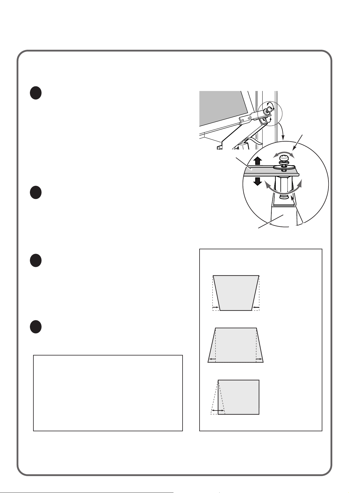
Adjust the Projection Mirror by turning the Adjusting
Nuts. Move the Projection Mirror up or down by
turning the Adjusting Nuts on the both sides of the
Projection Mirror. Adjust Screw(B) if it required.
Refer to the figure on the right for the image
movement with the Adjusting Nut.
Fix the Projection Mirror where the picture is
displayed properly. Fix the Screw(B) securely.
When fixing the Screw(B) the figure may be
distorted again. When it should happen, readjust
the Mirror following the steps 2 to 4.
Check Projection Image
Adjust Projection Mirror
Fix Projection Mirror
1
2
3
CAUTION
DO NOT STARE DIRECTLY INTO THE
LENS. EYE DAMAGE COULD RESULT.
WHEN ADJUSTING THE MIRROR, NEVER
TOUCH THE PARTS EXCEPT THE
MIRROR. IT MAY RESULT IN
ELECTRICAL SHOCK.
Turn off the projector and disconnect it from the AC
outlet.
Turn the projector off
4
Adjusting Nut
Screw(B)
Mirror Holder
Mirror Arm
Lower the
Mirror Holder.
Lift the Mirror
Holder.
Turn Adjusting Nuts to adjust
the screen image.
When turning the
Adjusting Nuts on both
sides to the right, the
lower part of the image
becomes narrow.
When turning the
Adjusting Nuts on both
sides to the left, the
lower part of the image
is stretched.
When turning the
Adjusting Nuts on one
side to the left or the
right, one side of the
lower part of the figure
is shortened or
stretched.
Page 7

6
ASSEMBLE STORAGE SPACES
Replace the Back Cover to the Top Cabinet. Turn
the Back Cover over, and fix the cover in the
reverse to the initial position.
Replace Back Cover
1
Back Cover
Screws (14 pcs)
IInsert the Shelves' Pins into appropreate position
of the walls of Storage Spaces. Install the
Compartment Shelves in Storage Spaces.
1. Remove the Hinge Covers by removing the 2
screws of each Hinge.
2. Hold the Glass Doors between the Glass Hinges
and the Hinge Covers. Install the Glass Doors so
that the side with the Holder Magnet is matched
to the magnet inside of the Storage Spaces. Do
not install the Glass Doors in the reverse.
Tighten the screws and fix the Glass Doors.
1. When adjusting the position of the Glass Doors,
loose the Screws(A) and move the Glass Doors
with the Hinges to the arrow direction until the
surface of the door matches to the surface of the
Cabinet Front.
2. When adjusting the tilt of the Glass Doors, adjust
the Screws(B) (lower and upper) and move the
Glass Doors.
Install Glass Doors
Adjustments of Doors
Install Compartment Shelves
2
3
4
Holder Magnet
Screws
(2pcs x 4)
Glass Door
Screw(A)
Screw(B)
Shelves' Pins
(4 pcs X 4)
Compartment
Shelves (4 pcs)
Holder Cover
Page 8

Turn Lock Bolts to the direction indicated on the
figure to lock the cabinet on the floor. Make sure
that all the Casters are slightly raised from the floor.
The tilt of Cabinet can be also adjusted with these
Lock Bolts.
Lock the Cabinet
1
CAUTION
BE SURE TO LOCK THE CABINET WITH
LOCK BOLTS PROPERLY. IF THE
CABINET IS NOT LOCKED, CABINET IS
UNSTABLE AND MAY FALL DOWN.
Cabinet Dimensions ( W x H x D ) : 1532 mm (60.3") x 1968mm (77.5" ) x 747mm (29.4" )
Net Weight : 145kg (319.7lbs )
7
LOCK CABINET
Letting the
cabinet down to
move it.
Lifting the
cabinet up to
settle it.
Lock Bolt
 Loading...