

Page 1

SERVICE MANUAL LCD Television
FILE NO.
Original Version
Chassis Series: UE5-B
N7DE
Model No. LCD-42K40TD
Give complete “SERVICE REF. NO.” for
parts order or servicing. It is shown on the
rating plate at the cabinet back of the unit.
This T.V. receiver will not work properly in
foreign countries where the television
transmission system and power source differ from the design specifications. Refer to
the specification table.
Product Code: 1-130-184-04
Contents
Safety Notice . . . . . . . . . . . . . . . . . . . . . . . . . . . 2
Specifications . . . . . . . . . . . . . . . . . . . . . . . . . . . 3
Chassis Block Diagrams . . . . . . . . . . . . . . . . . . 4-5
IC Block Diagrams . . . . . . . . . . . . . . . . . . . . . . . 6-8
On-screen Service Menu system . . . . . . . . . . . . 9-10
Service Adjustments . . . . . . . . . . . . . . . . . . . . . 11-13
Mechanical Disassembly . . . . . . . . . . . . . . . . . . 14-15
Chassis Electrical Parts List . . . . . . . . . . . . . . . 16-31
Cabinet Parts List . . . . . . . . . . . . . . . . . . . . . . . 32
PCB Assemble . . . . . . . . . . . . . . . . . . . . . . . . . . 33-34
Printed Wiring Board . . . . . . . . . . . . . . . . . . . . . 35-37
Schematic Diagram . . . . . . . . . . . . . . . . . . . . . . 38-43
REFERENCE NO. SM3010465
Service Ref. No. LCD-42K40TD-00
Page 2

2
Safety Notice
Safety Precautions
The following precautions must be observed.
1:Comply with all caution and safety-related notes provided on the cabinet back, cabinet bottom, inside the
cabinet or on the chassis.
2:When replacing a chassis in the cabinet, always be certain that all the protective devices are installed
properly, such as, control knobs, adjustment covers or shields, barriers, etc..
DO NOT OPERATE THIS TELEVISION WITHOUT THE PROTECTIVE SHIELD IN POSITION AND
PROPERLY SECURED
3:Before replacing the cabinet cover, thoroughly inspect the inside of the cabinet to see that no stray parts or
tools have been left inside.
Before returning any televison to the customer, the service personnel must be sure that it is completely safe
to operate without danger of electrical shock.
Product Safety Notice
Product safety should be considered when a component replacement is made in any area of a receiver.
Components indicated by mark in the parts list and the schematic diagram designate components in
It is particularly recommended that only parts designated on the parts list in this manual be used for
component replacement designated by mark .
No deviations from resistance wattage or voltage ratings may be made for replacement items designated
by mark .
Page 3

3
Model LCD-42K40TD
Maximum Visible Range
106cm
Picture Resolution
1920(H) x 1080(V)
Viewable Angle(L。/3) L/R:+/-89D, U/D:+/-89D
Brightness 500cd/m²
Mobile Trailer Time 5ms
Voltage AC110-242V 50/60Hz
Power Consumption 188W
Power Management VESA DPMS
Digital TV System DVB-T(2K/8K COFDM), Band Wide: 7MHZ
Video decoder:MPEG2 MP@HL
Audio decoder:MPEG1,MPEG2(Layer I/II),and DOLBY Digital(AC3)
Analog TV System Colour System:PAL,SECAM,NTSC/NTSC4.43(only AV)
Sound System:D/K,I,B/G,
Stereo System:NICAM,A2/IGR(German Stereo)
Channel Coverage - VHF: 0-12
- UHF: 27-69,
- MATV: UHF 20-27, UHF 70-75, S2-S44
Speaker Size Mains: 6cm x 12cm x 2pcs
Sound speciality Maximum Output Power is 10W+10W
Input terminals PC input terminal : RGB X 1 HDMI terminal: x3
Audio: Mini stereo jack x 1 (Audio input of PC)
Video: Composite video terminals x1 ()
S-VIDEO input: x 1 (DIN 4-pin, Y/C separate signal input)
DVD input: Component video input Y, CB/PB, CR/PR input x 1
Audio input: (R/L) x 4 (400mVrms)
Output terminals
Video Monitor Output:
Audio Monitor Output: R/L x 2 (
S/P DIF (Coaxial) Output x 1
Headphone Jack : Mini stereo jack x1
Dimensions
(Width x Height x Depth) 1009.5mm X 674.8mm X 271.6mm (Including Stand)
Net Weight
(Including Stand ) 18 KG
Operating Environment
Operating Temperature 0ºC~40ºC(32ºF~104ºF
)
Storage Temperature -10ºC~50ºC(14ºF~122ºF
)
Page 4

4
Chassis Block Diagrams
for HDCP
5V VA
5V STB
SPI FLASH
(option for air
update)
TUNER
TDTC-G501D
DVB-T
DEMODULATOR
CE6353
IF-PLL
TDA9886
VGA
HDMI_2
HDMI_3
1/3
SWITCH
PS321
HDMI
PORTS
CVBS0P
SIF
TS
DDR
UART
DDR SDRAM
256Mb x2
UART
I/F
SPI
DUAL
LVDS
LG PANEL
LC420WUN-SCB1
MUX
LINE
AUDIO
OUT
OP AMP
4558R
POWER
AMPLIFIER
TDA3124D2
IR
KEY BOARD
IR
USB
HEADER
EEPROM
24C32
DDCR
R/G/B 1
Y/Pb/Pr
R/G/B 0
24C02CT
AV1
HDMI_1
AV OUT
H.PHONE
EEPROM
24C512
SPDIF
SPDIFO
CVBS1P
CVBSO
LINE OUT1
10W
10W
HEAD PHONE
OUTPUT
CVBS/L/R
HP-L
R/G/B
JACK
LINE IN2
L
/
R
L/R
LINE IN1
L/R
Y/Pb/Pr
L/R
LINE IN3
L/R
CVBS
MSD1
09CL- H
DVB LCD/PDP DTV
PROCESSOR
MCU
VIDEO DEC
MPEG2 MP@HL DEC
MPEGI&II,AC3 DEC
NICAM/A2
SCALER
HDMI
LVDS
Q24C02CT/ SN-P
QNJM4558M---P
SPI FLASH
32Mb
QRCLAMP0524PP
1LB4J
11B0580M
TS
IF-
IF+
IIC1
IF_AGC
IF_TV
TV-VID
SIF P/M
I2C
RF-AGC
RST
20.48M
12MHz
I2C
UAR
FOR SOFT DEBUG
L
R
RESET
Q
PS321TQFP80M
USB
ESD
ESD
ESD
4MH
IIC1
IIC2
IIC3
HPD3
HPD1
HPD2
DDCDA
I2C-DDC
HOTPLUG
MUTE1
AU AMP
TPA6110
MUTE2
QTPA6110A2--P
KEY
IIC2
SPDIF
HP-R
HP-L
HP-R
RS232_I
UART1
RXD/TXD
QTDA9886TSV4P
S_VIDEO
MAX232
C
Y
CVBS4P
CVBS6P
UAR
for external
u
p
date
BUFFER
Page 5

5
CPU
Block Diagrams
MSD109CL-H
Page 6

6
256Mb TSOP-II Package Pinout
V
DD
1
66Pin TSOP
II
(400mil x 875mil)
DQ
0
2
V
DDQ
3
NC
4
DQ
1
5
V
SSQ
6
NC
7
DQ
2
8
V
DDQ
9
NC
10
DQ
3
11
V
SSQ
12
BA
0
20
CS
19
RAS
18
CAS
17
WE
16
NC
15
V
DDQ
14
NC
13
V
DD
27
A
3
26
A
2
25
A
1
24
A
0
23
AP/A
10
22
BA
1
21
V
SS
54
DQ
7
53
V
SSQ
52
NC
51
DQ
6
50
V
DDQ
49
NC
48
DQ
5
47
V
SSQ
46
NC
45
DQ
4
44
V
DDQ
43
A
11
35
36
CKE
37
CK
38
DM
39
V
REF
40
V
SSQ
41
NC
42
V
SS
55
A
4
56
A
5
57
A
6
58
A
7
59
A
8
60
A
9
34
(0.65mm Pin Pitch)
33
32
31
30
29
28
61
62
63
64
65
66
NC
NC
NC
NC
NC
V
DD
NC
DQS
NC
V
SS
CK
NC
A
12
V
SS
NC
V
SSQ
NC
DQ
3
V
DDQ
NC
NC
V
SSQ
NC
DQ
2
V
DDQ
A
11
CKE
CK
DM
V
REF
V
SSQ
NC
V
SS
A
4
A
5
A
6
A
7
A
8
A
9
NC
DQS
NC
V
SS
CK
NC
A
12
V
DD
NC
V
DDQ
NC
DQ
0
V
SSQ
NC
NC
V
DDQ
NC
DQ
1
V
SSQ
BA
0
CS
RAS
CAS
WE
NC
V
DDQ
NC
V
DD
A
3
A
2
A
1
A
0
AP/A
10
BA
1
NC
NC
NC
NC
NC
V
DD
Bank Address
BA0~BA1
Auto Precharge
A10
64Mb x 4
32Mb x 8
V
DD
DQ
0
V
DDQ
DQ
1
DQ
2
V
SSQ
DQ
3
DQ
4
V
DDQ
DQ
5
DQ
6
V
SSQ
BA
0
CS
RAS
CAS
WE
LDM
V
DDQ
DQ
7
V
DD
A
3
A
2
A
1
A
0
AP/A
10
BA
1
NC
LDQS
NC
NC
NC
V
DD
V
SS
DQ
15
V
SSQ
DQ
14
DQ
13
V
DDQ
DQ
12
DQ
11
V
SSQ
DQ
10
DQ
9
V
DDQ
A
11
CKE
CK
UDM
V
REF
V
SSQ
DQ
8
V
SS
A
4
A
5
A
6
A
7
A
8
A
9
NC
UDQS
NC
V
SS
CK
NC
A
12
16Mb x 16
IC Block Diagrams
K4H561638H
Page 7

7
IC
Block Diagrams
CE6353(INTEL)
Page 8

8
IC Block Diagrams
TPA3124D2PWPR
TDA9886
1
2
3
4
5
6
7
8
9
10
11
12
PVCCL
SD
PVCCL
MUTE
LIN
RIN
BYPASS
AGND
AGND
PVCCR
VCLAMP
PVCCR
24
23
22
21
20
19
18
17
16
15
14
13
PGNDL
PGNDL
LOUT
BSL
AVCC
AVCC
GAIN0
GAIN1
BSR
ROUT
PGNDR
PGNDR
PWP (TSSOP) PACKAGE
(TOP VIEW)
Page 9

9
On-screen Service Menu System
General
This set has an On-screen Menu system included in the CPU that allows remote operation for most of the
service adjustments.
r How to select the service item and adjust data:
On-screen Service Menu System
Quick operation is needed to enter Service Mode.
r How to enter the Service Menu
1. Press and hold the MENU button on Side Controls.
2. Keep pressing the MENU button and press “1” button on the remote control, and the Service Mode will be
displayed.
or button to navigate through the
options or adjust an option. Press OK button to confirm a selection or
enter a sub-menu.
r To exit service mode
Press MENU button to exit service mode.
OK
Open or close the On-Screen Menu.
MENU button
Side Controls
[ Service Mode Menu ]
Service Mode
ADC ADJUST
PICTURE MODE
W/B ADJUST
WHITE PATTERN : OFF
RFAGC ADJUST : 16
SSC ADHYST
BACKLIGHT ADJUST
UE5B_V2.26_LG42_100301
ADC ADJUST
Page 10

10
■ Service Adjustment Data Table
On-screen Service Menu System
ADC ADJUST SOURCE RGB
R-GAIN 97
G-GAIN 103
B-GAIN 101
R-OFFSET 133
G-OFFSET 123
B-OFFSET 131
AUTO ADC <FAIL/SUCCESS>
SOURCE YPbPr(SD)
R-GAIN 65
G-GAIN 61
B-GAIN 66
R-OFFSET 128
G-OFFSET 128
B-OFFSET 128
AUTO ADC <FAIL/SUCCESS>
SOURCE YPbPr(HD)
R-GAIN 63
G-GAIN 61
B-GAIN 66
R-OFFSET 128
G-OFFSET 128
B-OFFSET 128
AUTO ADC <FAIL/SUCCESS>
W/B ADJUST BASE R-GAIN 64
SOURCE ALL BASE G-GAIN 64
TEMPERTURE ALL BASE B-GAIN 64
Page 11
11
Service Adjustments
CAUTION !
Do not attempt to adjust service adjustments not listed below otherwise it may cause loss of performance
and for correct operation.
r Setting the Initial data
This adjustment is controlled by the CPU (IC5500) through the IIC Bus Data Line in the chassis, and those
adjustment data are memorized the memory IC (IC5750). Therefore, Main board or the memory IC (IC5750)
is replaced, these data will be disappeared. Readjust should be made. Initial data is provided in the CPU
ROM, when the memory IC (IC5750) is replaced with new one. CPU ROM data is loaded into the memory.
Initial data is provided to operating the monitor basically. For operating the monitor quality performance,
further adjustment is required following chassis electrical adjustment.
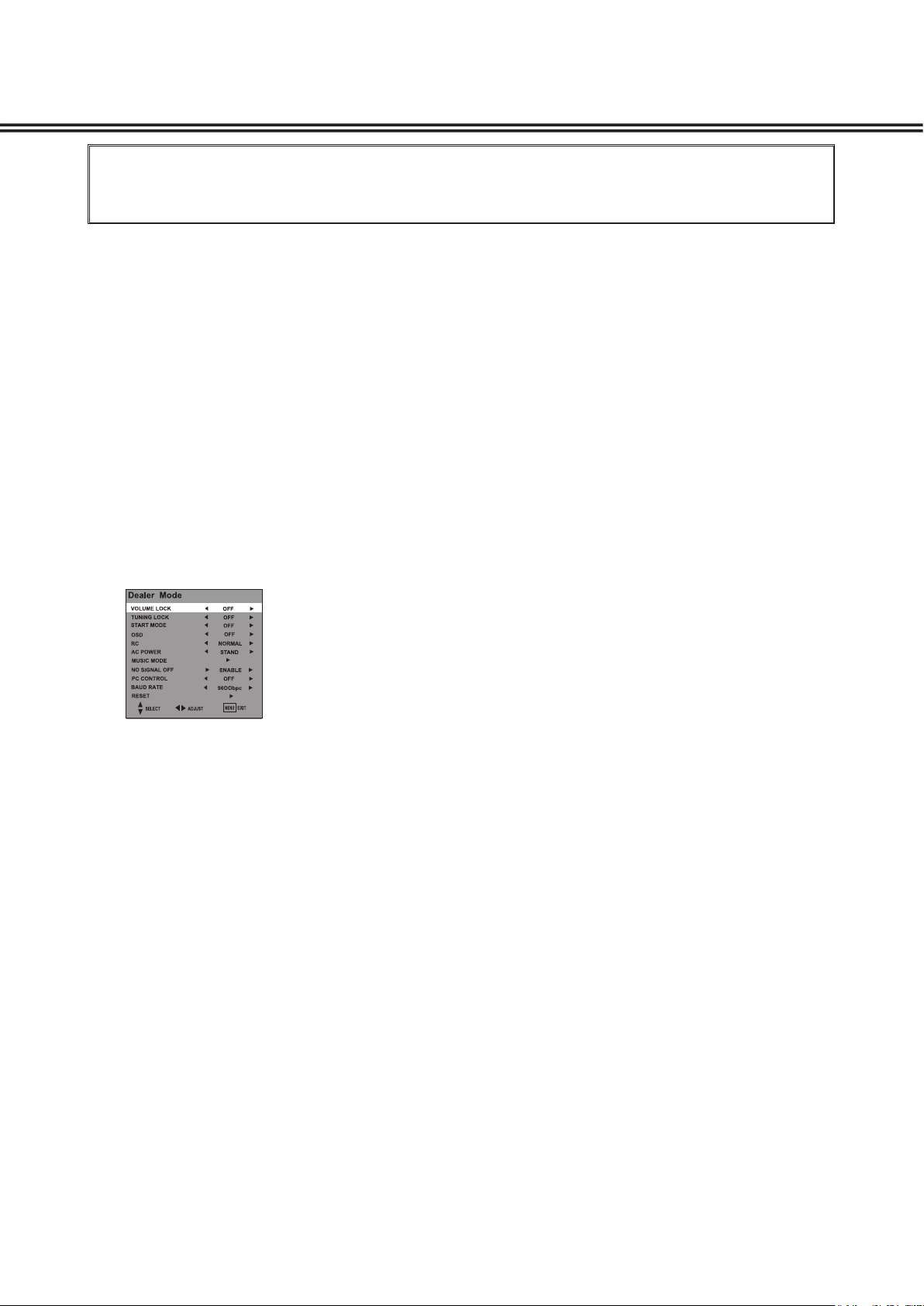
1. Enter the Dealer Mode, and select RESET.
r How to enter the Dealer Mode.
Press the MENU button on Side Controls, the screen menu will be displayed.
Press the INFO button on the Remote Control, you can enter the Dealer Mode as following.
or OK button to select RESET and confirm to
returns most setting
values to the factory default
settings.
(Note: After executed reset function, ADC ADJUST and W/B ADJUST should be readjusted. Please
enter Service Mode to adjust data.)
2. Enter the Service Mode, and select ADC ADJUST / W/B ADJUST to adjust the data according
"Service Adjustment Data Table" on page 10.
r How to enter the Service Mode. Please refer to page 9.
Page 12

12
Service Adjustments
r ADC ADJUST
1. Enter the Service Mode.
2. Select "ADC ADJUST" by pressing
button, then press OK button to enter ADC ADJUST menu.
3. Press button to select "SOURCE" item, press or button to select RGB, YPbPr(SD) or
YPbPr(HD).
(1). Receive signal from PC input. And set ANSI pattern contrast in PC mode.Receive signal from PC input. And set ANSI pattern contrast in PC mode.
(2). Enter the ADC ADJUST menu. PressEnter the ADC ADJUST menu. PressPress button to select "SOURCE" item
(3). Press or button to select RGB.
(4). Press button to select AUTO ADC item, then press OK button.
(1).
(2). Enter the ADC ADJUST menu. PressEnter the ADC ADJUST menu. PressPress button to select "SOURCE" item.
(3). Press or button to select YPbPr (SD).
(4). Press button to select AUTO ADC item, then press OK button.
(1).
(2). Enter the ADC ADJUST menu. PressEnter the ADC ADJUST menu. PressPress button to select "SOURCE" item.
(3). Press or button to select YPbPr (HD).
(4). Press button to select AUTO ADC item, then press OK button.
4. Exit the Service Mode.
Wait for about several seconds until AUTO ADC adjust completed. Then press MENU button to exit.
Note: If you want to adjust any item, please consult qualified service personnel.
RGB
YPbPr (SD)
YPbPr (HD)
ADC ADJUST
SOURCE : RGB
R-GAIN : 117
G-GAIN : 121
B-GAIN : 123
R-OFFSET : 131
G-OFFSET : 145
B-OFFSET : 123
AUTO ADC FAIL
SOURCE : RGB
Page 13

13
r
W/B ADJUST
Pattern
Condition
Picture Mode: STANDARD
Color Temperature: NORMAL
Aging Time: More than 10 minutes
Adjustment
1. Enter the Service Mode.
2. Select "W/B ADJUST" by pressing button, then press OK button to enter W/B ADJUST menu.
3. Exit the Service Mode.
After adjustment, confirm white balance again by normal picture.
Note: • Maybe BASE data for each TV set is different. And the items are for factory setting and
Service Centre.
• SOURCE items are for all input source gain. Usually the items can not be adjusted.
• USER items are just for user setting. Usually the items can not be adjusted.
• If you want to adjust any item, please consult qualified service personnel.
Service Adjustments
W/B ADJUST
BASE R-GAIN : 78
BASE G-GAIN : 78
BASE B-GAIN : 78
SOURCE : DTV
SOURCE R-GAIN : 25
SOURCE G-GAIN : 25
SOURCE B-GAIN : 25
TEMPERATURE : Normal
USER R-GAIN : 25
USER G-GAIN : 25
USER B-GAIN : 25
R-OFFSET : 128
G-OFFSET : 128
B-OFFSET : 128
COPY ALL
BASE R-GAIN : 78
Page 14

14
Mechanical Disassembly
(一) Lid Back Removal
Remove screws A and B, Take the Lid Back off.
(A: 2pcs, B: 3pcs)
A
LID
BACK
Picture 1.
A
B
B
B
POWER BOARD
MAIN
BOARD
Picture 2.
Page 15

15
Mechanical Disassembly
(三) Cabinet Back Removal
Picture 3.
MAIN BOARD
E
POWER BOARD
A
E
POWER BOARD HOLDER
F
G
G
Picture 4.
C C
C
C
C
C
C
D
D
D
D
D
C
C
C
C
C
C
C
C
C
E
STAND BASE
Note: When remove Power Board and MAIN BOARD, please keep EARTH BRKT PWB.
And make sure of installing EARTH BRKT PWB if assemble the LCD TV set again.
EARTH BRKT
POWER PWB
EARTH BRKT
MAIN PWB
(二) Chassis Board and Stand Base Removal
1. Remove Screw E, take Power Board Holder, then take Power Board off.
2. Remove Screw A and E, take Main Board off.
3. Remove Screw F and G, take Stand Base off.
(A: 3pcs, E: 12pcs, F: 2pcs, G: 4pcs)
Remove Screw C and D, take the Cabinet Back off.
(C: 16pcs, D: 5pcs)
Page 16

16
N7DE
OUT OF CIRCUIT BOARD
LCD PANEL
EL901 6451024480 LCD(LC420WUN-SCB1)
MISCELLANEOUS
SP901 6520014473 SPEAKER,8
6520018327 SPEAKER,8
SP902 6520014473 SPEAKER,8
6520018327 SPEAKER,8
WCN1-660 6520026285 NON STANDARD WIRE ASSY
6520025233 NONSTANDARD WIRE ASSY
WSP9L 6520028623 NON STANDARD WIRE
6520023987 NONSTANDARD WIRE ASSY
WSP9R 6520028661 NON STANDARD WIRE ASSY
6520028401 NONSTANDARD WIRE ASSY
W2002-20 6103458076 STANDARD WIRE ASSY-JPN
6103453613 STANDARD WIRE
W662-001 6103458106 STANDARD WIRE ASSY-JPN
6103450728 STANDARD WIRE
W680-150 6103399980 STANDARD WIRE ASSY-JPN
6103391977 STANDARD WIRE
W7300 6520026513 CORD 51PIN (LVDS)
W8001-19 6520028647 NONSTANDARD WIRE ASSY
6520028425 NONSTANDARD WIRE ASSY
W8002-19 6103397085 STANDARD WIRE ASSY
6103508283 STANDARD WIRE ASSY-N5JV
6103352749 STANDARD WIRE
W901 6450956072 CORD,POWER-2.23MK-VAR-2
6103501529 ASSY,PWB,MAIN,N7DE
1AA0B10S286EA
TRANSISTOR
Q001 4060214407 TR MMBTSC3928R
4050144519 TR 2SC2412K T146 R
4050144618 TR 2SC2412K T146 S
4050158724 TR 2SC2812-L6-TB
4050158922 TR 2SC2812-L7-TB
4051631612 TR 2SC2812N-L6-TB0
4051739813 TR 2SC3928A1R
4051739912 TR 2SC3928A1S
Q002 4060214407 TR MMBTSC3928R
4050144519 TR 2SC2412K T146 R
4050144618 TR 2SC2412K T146 S
4050158724 TR 2SC2812-L6-TB
4050158922 TR 2SC2812-L7-TB
4051631612 TR 2SC2812N-L6-TB0
4051739813 TR 2SC3928A1R
4051739912 TR 2SC3928A1S
Q003 4060214407 TR MMBTSC3928R
4050144519 TR 2SC2412K T146 R
4050144618 TR 2SC2412K T146 S
4050158724 TR 2SC2812-L6-TB
4050158922 TR 2SC2812-L7-TB
!
!
Chassis Electrical Parts List
Ref. No. Part No. Description Ref. No. Part No. Description
Product safety should be considered when a component replacement is made in any area of a receiver.
Components indicated by a mark in this parts list and the circuit diagram show components whose value have
special significance to product safety. It is particularly recommended that only parts specified on the following parts
list be used for components replacement pointed out by the mark.
!
Note: Parts order must contain Chassis No., Part No., and descriptions. The main PCB unit will be supplied without tuner and
flyback transformer. They should be ordered separately.
NOTES:
Read description in the Capacitor and Resistor as follows:
CAPACITOR
CERAMIC 100P K 50V
Rated Voltage
Tolerance Symbols:
Less than 10pF
A : Not specified B : ±0.1pF C : ±0.25pF
D : ±0.5pF F : ±1PF G : ±2pF
R : ±0.25-0pF S : ±0-0.25pF E : +0-1pF
More than 10pF
A : Not specified B : ±0.1% C : ±0.25%
D : ±0.5% F : ±1% G : ±2%
H : ±3% J : ±5% K : ±10%
L : ±15% M : ±20% N : ±30%
P : +100-0% Q : +30-10% T : +50-10%
U : +75-10% V : +20-10% W : +100-10%
X : +40-20% Y : +150-10% Z : +80-20%
Rated value: P=pico farad, U=micro farad
Material:
CERAMIC........... Ceramic
MT-PAPER......... Metallized Paper
POLYESTER...... Polyester
MT-POLYEST.....Metallized Polyester
POLYPRO.......... Polypropylene
MT-POLYPRO.... Metallized Polypropylene
COMPO FILM..... Composite film
MT-COMPO........ Metallized Composite
STYRENE........... Styrene
TA-SOLID........... Tantalum Solid
AL-SOLID........... Aluminium Solid
ELECT................ Electrolytic
NP-ELECT.......... Non-polarised Electrolytic
OS-SOLID.......... Aluminium Solid with Organic Semiconductive Electrolytic
DL-ELECT.......... Double Layered Electrolytic
RESISTOR
CARBON 4.7K J A 1/4W
Performance Symbols:
A: General B: Non flammable Z: Low noise
Other: Temperature coefficient
Tolerance Symbols:
A: ±0.05% B: ±0.1% C: ±0.25% D: ±0.5%
F: ±1% G: ±2% J: ±5% K: ±10%
M: ±20% P: +5-15%
Rated value, ohms:
K: 1,000, M: 1,000,000
Material:
CARBON........... Carbon
MT-FILM............ Metal Film
OXIDE-MT......... Oxide Metal Film
SOLID................ Composition
MT-GLAZE......... Metal Glaze
WIRE WOUND... Wire Wound
CERAMIC RES.. Ceramic
FUSIBLE RES.... Fusible
Rated Wattage
Page 17

4051631612 TR 2SC2812N-L6-TB0
4051739813 TR 2SC3928A1R
4051739912 TR 2SC3928A1S
Q004 4060214407 TR MMBTSC3928R
4050144519 TR 2SC2412K T146 R
4050144618 TR 2SC2412K T146 S
4050158724 TR 2SC2812-L6-TB
4050158922 TR 2SC2812-L7-TB
4051631612 TR 2SC2812N-L6-TB0
4051739813 TR 2SC3928A1R
4051739912 TR 2SC3928A1S
Q006 4060214407 TR MMBTSC3928R
4050144519 TR 2SC2412K T146 R
4050144618 TR 2SC2412K T146 S
4050158724 TR 2SC2812-L6-TB
4050158922 TR 2SC2812-L7-TB
4051631612 TR 2SC2812N-L6-TB0
4051739813 TR 2SC3928A1R
4051739912 TR 2SC3928A1S
Q007 4060214407 TR MMBTSC3928R
4050144519 TR 2SC2412K T146 R
4050144618 TR 2SC2412K T146 S
4050158724 TR 2SC2812-L6-TB
4050158922 TR 2SC2812-L7-TB
4051631612 TR 2SC2812N-L6-TB0
4051739813 TR 2SC3928A1R
4051739912 TR 2SC3928A1S
Q101 4060214407 TR MMBTSC3928R
4050144519 TR 2SC2412K T146 R
4050144618 TR 2SC2412K T146 S
4050158724 TR 2SC2812-L6-TB
4050158922 TR 2SC2812-L7-TB
4051631612 TR 2SC2812N-L6-TB0
4051739813 TR 2SC3928A1R
4051739912 TR 2SC3928A1S
Q1062 4060214407 TR MMBTSC3928R
4050144519 TR 2SC2412K T146 R
4050144618 TR 2SC2412K T146 S
4050158724 TR 2SC2812-L6-TB
4050158922 TR 2SC2812-L7-TB
4051631612 TR 2SC2812N-L6-TB0
4051739813 TR 2SC3928A1R
4051739912 TR 2SC3928A1S
Q1063 4060214407 TR MMBTSC3928R
4050144519 TR 2SC2412K T146 R
4050144618 TR 2SC2412K T146 S
4050158724 TR 2SC2812-L6-TB
4050158922 TR 2SC2812-L7-TB
4051631612 TR 2SC2812N-L6-TB0
4051739813 TR 2SC3928A1R
4051739912 TR 2SC3928A1S
Q1064 4060214407 TR MMBTSC3928R
4050144519 TR 2SC2412K T146 R
4050144618 TR 2SC2412K T146 S
4050158724 TR 2SC2812-L6-TB
4050158922 TR 2SC2812-L7-TB
4051631612 TR 2SC2812N-L6-TB0
4051739813 TR 2SC3928A1R
4051739912 TR 2SC3928A1S
Q1065 4060214407 TR MMBTSC3928R
4050144519 TR 2SC2412K T146 R
4050144618 TR 2SC2412K T146 S
4050158724 TR 2SC2812-L6-TB
4050158922 TR 2SC2812-L7-TB
4051631612 TR 2SC2812N-L6-TB0
4051739813 TR 2SC3928A1R
4051739912 TR 2SC3928A1S
Q5900 4052203115 TR ISA1235AC1E
4052203016 TR ISA1235AC1F
4060214308 TR MMBTSA1235F
4051345925 TR 2SA1037AK-T146-R
4051472215 TR 2SA1037AK-S-T146
4051739615 TR 2SA1235A1E
4051739714 TR 2SA1235A1F
Q6501 4060214407 TR MMBTSC3928R
4050144519 TR 2SC2412K T146 R
4050144618 TR 2SC2412K T146 S
4050158724 TR 2SC2812-L6-TB
4050158922 TR 2SC2812-L7-TB
4051631612 TR 2SC2812N-L6-TB0
4051739813 TR 2SC3928A1R
4051739912 TR 2SC3928A1S
Q6502 4060214407 TR MMBTSC3928R
4050144519 TR 2SC2412K T146 R
4050144618 TR 2SC2412K T146 S
4050158724 TR 2SC2812-L6-TB
4050158922 TR 2SC2812-L7-TB
4051631612 TR 2SC2812N-L6-TB0
4051739813 TR 2SC3928A1R
4051739912 TR 2SC3928A1S
Q6503 4060214407 TR MMBTSC3928R
4050144519 TR 2SC2412K T146 R
4050144618 TR 2SC2412K T146 S
4050158724 TR 2SC2812-L6-TB
4050158922 TR 2SC2812-L7-TB
4051631612 TR 2SC2812N-L6-TB0
4051739813 TR 2SC3928A1R
4051739912 TR 2SC3928A1S
Q6801 4060214407 TR MMBTSC3928R
4050144519 TR 2SC2412K T146 R
4050144618 TR 2SC2412K T146 S
4050158724 TR 2SC2812-L6-TB
4050158922 TR 2SC2812-L7-TB
4051631612 TR 2SC2812N-L6-TB0
4051739813 TR 2SC3928A1R
4051739912 TR 2SC3928A1S
Q6803 4060214407 TR MMBTSC3928R
4050144519 TR 2SC2412K T146 R
4050144618 TR 2SC2412K T146 S
4050158724 TR 2SC2812-L6-TB
4050158922 TR 2SC2812-L7-TB
4051631612 TR 2SC2812N-L6-TB0
4051739813 TR 2SC3928A1R
4051739912 TR 2SC3928A1S
Q6805 4060214407 TR MMBTSC3928R
4050144519 TR 2SC2412K T146 R
4050144618 TR 2SC2412K T146 S
4050158724 TR 2SC2812-L6-TB
4050158922 TR 2SC2812-L7-TB
4051631612 TR 2SC2812N-L6-TB0
4051739813 TR 2SC3928A1R
4051739912 TR 2SC3928A1S
Q6806 4060214407 TR MMBTSC3928R
4050144519 TR 2SC2412K T146 R
4050144618 TR 2SC2412K T146 S
4050158724 TR 2SC2812-L6-TB
4050158922 TR 2SC2812-L7-TB
4051631612 TR 2SC2812N-L6-TB0
4051739813 TR 2SC3928A1R
4051739912 TR 2SC3928A1S
Q7207 4052203115 TR ISA1235AC1E
4052203016 TR ISA1235AC1F
4060214308 TR MMBTSA1235F
4051345925 TR 2SA1037AK-T146-R
17
N7DE
Ref. No. Part No. Description Ref. No. Part No. Description
Page 18

18
N7DE
4051472215 TR 2SA1037AK-S-T146
4051739615 TR 2SA1235A1E
4051739714 TR 2SA1235A1F
Q7208 4060214407 TR MMBTSC3928R
4050144519 TR 2SC2412K T146 R
4050144618 TR 2SC2412K T146 S
4050158724 TR 2SC2812-L6-TB
4050158922 TR 2SC2812-L7-TB
4051631612 TR 2SC2812N-L6-TB0
4051739813 TR 2SC3928A1R
4051739912 TR 2SC3928A1S
Q8000 4060214407 TR MMBTSC3928R
4050144519 TR 2SC2412K T146 R
4050144618 TR 2SC2412K T146 S
4050158724 TR 2SC2812-L6-TB
4050158922 TR 2SC2812-L7-TB
4051631612 TR 2SC2812N-L6-TB0
4051739813 TR 2SC3928A1R
4051739912 TR 2SC3928A1S
Q8001 4060214407 TR MMBTSC3928R
4050144519 TR 2SC2412K T146 R
4050144618 TR 2SC2412K T146 S
4050158724 TR 2SC2812-L6-TB
4050158922 TR 2SC2812-L7-TB
4051631612 TR 2SC2812N-L6-TB0
4051739813 TR 2SC3928A1R
4051739912 TR 2SC3928A1S
INTEGRATED CIRCUIT
IC001 4096910413 IC TPA3123D2PWPR
4106847408 IC TPA3124D2PWPR
IC003 4096910314 IC TPA6110A2DGNR
IC1004 4096990514 IC FMS6141S5X
IC101 4095498219 IC TDA9886TS/V4
IC102 4106852303 IC WJCE6353SL9G5
IC1501 4094620324 IC 24LC21AT/SN
IC3100 4093870918 IC BA4558F-E2
IC5500 4106847507 IC MSD109CL-H-LF
IC5600 4106852402 IC K4H561638J-LCCC
IC5601 4106852402 IC K4H561638J-LCCC
IC5750 4107101905 IC W25X32VSSIG-N7DE
4107159807 IC AT25DF321A-SH-B-N7DE
IC5900 4106716308 IC XC6108N28AMR
IC6500 4096933818 IC PS321TQFP80G
IC6501 4096925714 IC RCLAMP0524P
IC6502 4096925714 IC RCLAMP0524P
IC6503 4096925714 IC RCLAMP0524P
IC6504 4096925714 IC RCLAMP0524P
IC6505 4096925714 IC RCLAMP0524P
IC6506 4096925714 IC RCLAMP0524P
IC6700 4096444017 IC AMS1117-1.8
4096836416 IC LM1117S-1.8
IC6701 4095599015 IC AMS1117-3.3
4096836515 IC LM1117S-3.3
IC6800 4095598919 IC AMS1117-2.5
4097014219 IC LM1117S-2.5
IC6801 4095599015 IC AMS1117-3.3
4096836515 IC LM1117S-3.3
IC6802 4095599015 IC AMS1117-3.3
4096836515 IC LM1117S-3.3
IC6803 4096941219 IC ST1S10PHR
IC6804 4052027711 TR TPC8109
4060221603 TR HAT1131R-EL-E
IC6901 4095599015 IC AMS1117-3.3
4096836515 IC LM1117S-3.3
IC8001 4106848405 IC AT24C512BN-SH-T
IC8002 4106256200 IC 24LC32AT-I/SNG—N3VP
IC8003 4096990415 IC FSA1156P6X
CAPACITOR
C001 4041084203 ELECT 470U M 35V
C002 4041044900 CERAMIC 0.1U K 50V
4040912606 CERAMIC 0.1U K 50V
4033670417 CERAMIC 0.1U K 50V
C003 4041167500 CERAMIC 1U K 16V
C004 4041167500 CERAMIC 1U K 16V
C005 4041167500 CERAMIC 1U K 16V
C006 4041167500 CERAMIC 1U K 16V
C007 4041044900 CERAMIC 0.1U K 50V
4040912606 CERAMIC 0.1U K 50V
4033670417 CERAMIC 0.1U K 50V
C008 4041084203 ELECT 470U M 35V
C009 4034502212 CERAMIC 0.22U K 25V
C010 4041081004 ELECT 100U M 35V
C011 4041044900 CERAMIC 0.1U K 50V
4040912606 CERAMIC 0.1U K 50V
4033670417 CERAMIC 0.1U K 50V
C012 4034502212 CERAMIC 0.22U K 25V
C013 4032569316 CERAMIC 0.47U Z 50V
C014 4032569316 CERAMIC 0.47U Z 50V
C015 4041064205 ELECT 1000U M 35V
C016 4041064205 ELECT 1000U M 35V
C017 4041167500 CERAMIC 1U K 16V
C018 4041044900 CERAMIC 0.1U K 50V
4040912606 CERAMIC 0.1U K 50V
4033670417 CERAMIC 0.1U K 50V
C029 4041032907 CERAMIC 0.01U K 50V
4040901204 CERAMIC 0.01U K 50V
4032152211 CERAMIC 0.01U K 50V
C030 4041036608 CERAMIC 0.22U K 16V
4032812412 CERAMIC 0.22U K 16V
C031 4041212903 CERAMIC 2.2U K 10V
4033827811 CERAMIC 2.2U K 10V
C032 4041131402 ELECT 47U M 10V
4040988304 ELECT 47U M 10V
C033 4041125401 ELECT 100U M 10V
4040987901 ELECT 100U M 10V
C034 4041125401 ELECT 100U M 10V
4040987901 ELECT 100U M 10V
C035 4041212903 CERAMIC 2.2U K 10V
4033827811 CERAMIC 2.2U K 10V
C037 4041044900 CERAMIC 0.1U K 50V
4040912606 CERAMIC 0.1U K 50V
4033670417 CERAMIC 0.1U K 50V
C055 4041079704 ELECT 100U M 50V
4040989608 ELECT 100U M 50V
C056 4041044900 CERAMIC 0.1U K 50V
4040912606 CERAMIC 0.1U K 50V
4033670417 CERAMIC 0.1U K 50V
C057 4041079704 ELECT 100U M 50V
4040989608 ELECT 100U M 50V
C058 4041044900 CERAMIC 0.1U K 50V
4040912606 CERAMIC 0.1U K 50V
4033670417 CERAMIC 0.1U K 50V
C100 4041047901 CERAMIC 22P J 50V
4040947608 CERAMIC 22P J 50V
4031459915 CERAMIC 22P J 50V
C1002 4041129201 ELECT 220U M 10V
4040988106 ELECT 220U M 10V
C1005 4041128600 ELECT 10U M 16V
4040969600 ELECT 10U M 16V
C1008 4041128600 ELECT 10U M 16V
4040969600 ELECT 10U M 16V
C101 4041047901 CERAMIC 22P J 50V
Ref. No. Part No. Description Ref. No. Part No. Description
Page 19

4040947608 CERAMIC 22P J 50V
4031459915 CERAMIC 22P J 50V
C102 4040944003 CERAMIC 0.1U Z 50V
C1021 4041038206 CERAMIC 10P J 50V
4040946304 CERAMIC 10P J 50V
C1024 4041038206 CERAMIC 10P J 50V
4040946304 CERAMIC 10P J 50V
C103 4041116102 ELECT 47U M 6.3V
4041102501 ELECT 47U M 6.3V
4040923602 ELECT 47U M 6.3V
C1035 4041123506 ELECT 4.7U M 50V
4040973409 ELECT 4.7U M 50V
C104 4040944003 CERAMIC 0.1U Z 50V
C105 4041128600 ELECT 10U M 16V
4040969600 ELECT 10U M 16V
C106 4040944003 CERAMIC 0.1U Z 50V
C1060 4041212903 CERAMIC 2.2U K 10V
4033827811 CERAMIC 2.2U K 10V
C1061 4041212903 CERAMIC 2.2U K 10V
4033827811 CERAMIC 2.2U K 10V
C1062 4041130801 ELECT 100U M 16V
4040971801 ELECT 100U M 16V
4041084104 ELECT 100U M 16V
C1063 4040944003 CERAMIC 0.1U Z 50V
C1064 4041212903 CERAMIC 2.2U K 10V
4033827811 CERAMIC 2.2U K 10V
C1066 4040944003 CERAMIC 0.1U Z 50V
C1067 4041212903 CERAMIC 2.2U K 10V
4033827811 CERAMIC 2.2U K 10V
C1068 4040944003 CERAMIC 0.1U Z 50V
C107 4041047901 CERAMIC 22P J 50V
4040947608 CERAMIC 22P J 50V
4031459915 CERAMIC 22P J 50V
C108 4041033904 CERAMIC 0.47U K 10V
4040950301 CERAMIC 0.47U K 10V
4033485823 CERAMIC 0.47U K 10V
C109 4041034109 CERAMIC 0.22U K 10V
4040950202 CERAMIC 0.22U K 10V
4033256314 CERAMIC 0.22U K 10V
C110 4041045204 CERAMIC 1500P K 50V
4040901303 CERAMIC 1500P K 50V
4031552111 CERAMIC 1500P K 50V
C112 4041032907 CERAMIC 0.01U K 50V
4040901204 CERAMIC 0.01U K 50V
4032152211 CERAMIC 0.01U K 50V
C113 4041032907 CERAMIC 0.01U K 50V
4040901204 CERAMIC 0.01U K 50V
4032152211 CERAMIC 0.01U K 50V
C114 4041032907 CERAMIC 0.01U K 50V
4040901204 CERAMIC 0.01U K 50V
4032152211 CERAMIC 0.01U K 50V
C115 4041037803 CERAMIC 390P J 50V
4040948506 CERAMIC 390P J 50V
4032150910 CERAMIC 390P J 50V
C116 4041034802 CERAMIC 0.01U K 16V
4041032907 CERAMIC 0.01U K 50V
4040950400 CERAMIC 0.01U K 16V
4040901204 CERAMIC 0.01U K 50V
C117 4041036707 CERAMIC 0.47U K 16V
4041109807 CERAMIC 0.47U K 16V
4033363517 CERAMIC 0.47U K 16V
C118 4041032402 CERAMIC 1000P K 50V
4040901105 CERAMIC 1000P K 50V
4031133815 CERAMIC 1000P K 50V
C123 4041034505 CERAMIC 0.1U K 16V
4040950509 CERAMIC 0.1U K 16V
4032989619 CERAMIC 0.1U K 16V
C124 4041038206 CERAMIC 10P J 50V
4040946304 CERAMIC 10P J 50V
4031669215 CERAMIC 10P J 50V
C125 4041038206 CERAMIC 10P J 50V
4040946304 CERAMIC 10P J 50V
4031669215 CERAMIC 10P J 50V
C126 4041034505 CERAMIC 0.1U K 16V
4040950509 CERAMIC 0.1U K 16V
4032989619 CERAMIC 0.1U K 16V
C127 4041034505 CERAMIC 0.1U K 16V
4040950509 CERAMIC 0.1U K 16V
4032989619 CERAMIC 0.1U K 16V
C130 4041125401 ELECT 100U M 10V
4040987901 ELECT 100U M 10V
C131 4041034505 CERAMIC 0.1U K 16V
4040950509 CERAMIC 0.1U K 16V
4032989619 CERAMIC 0.1U K 16V
C132 4040944003 CERAMIC 0.1U Z 50V
C133 4040954705 CERAMIC 0.022U Z 50V
C134 4041044207 CERAMIC 56P J 50V
4040948902 CERAMIC 56P J 50V
C135 4040944003 CERAMIC 0.1U Z 50V
C136 4040954200 CERAMIC 0.01U Z 50V
C1500 4041034505 CERAMIC 0.1U K 16V
4040950509 CERAMIC 0.1U K 16V
4032989619 CERAMIC 0.1U K 16V
C1501 4041040209 CERAMIC 100P J 50V
4040946403 CERAMIC 100P J 50V
C1502 4041040209 CERAMIC 100P J 50V
4040946403 CERAMIC 100P J 50V
C1505 4041047901 CERAMIC 22P J 50V
4040947608 CERAMIC 22P J 50V
4031459915 CERAMIC 22P J 50V
C1506 4041047901 CERAMIC 22P J 50V
4040947608 CERAMIC 22P J 50V
4031459915 CERAMIC 22P J 50V
C3100 4040947707 CERAMIC 220P J 50V
C3101 4041032402 CERAMIC 1000P K 50V
4040901105 CERAMIC 1000P K 50V
C3102 4033835212 CERAMIC 4.7U K 6.3V
C3103 4041032402 CERAMIC 1000P K 50V
4040901105 CERAMIC 1000P K 50V
C3104 4040947707 CERAMIC 220P J 50V
C3105 4033835212 CERAMIC 4.7U K 6.3V
C3106 4041130801 ELECT 100U M 16V
4040971801 ELECT 100U M 16V
C3107 4040944003 CERAMIC 0.1U Z 50V
C3108 4041130801 ELECT 100U M 16V
4040971801 ELECT 100U M 16V
C3112 4041045709 CERAMIC 2200U K 50V
4040913306 CERAMIC 2200P K 50V
4031134119 CERAMIC 2200P K 50V
C3113 4041045709 CERAMIC 2200U K 50V
4040913306 CERAMIC 2200P K 50V
4031134119 CERAMIC 2200P K 50V
C3114 4040913108 CERAMIC 0.018U K 50V
4040954606 CERAMIC 0.018U Z 50V
C3117 4040913108 CERAMIC 0.018U K 50V
4040954606 CERAMIC 0.018U Z 50V
C3119 4040944003 CERAMIC 0.1U Z 50V
C400 4041127900 ELECT 470U M 10V
4040988403 ELECT 470U M 10V
C402 4041034505 CERAMIC 0.1U K 16V
4040950509 CERAMIC 0.1U K 16V
4032989619 CERAMIC 0.1U K 16V
C403 4041129300 ELECT 470U M 16V
4040988700 ELECT 470U M 16V
19
N7DE
Ref. No. Part No. Description Ref. No. Part No. Description
Page 20

20
N7DE
C405 4041034505 CERAMIC 0.1U K 16V
4040950509 CERAMIC 0.1U K 16V
4032989619 CERAMIC 0.1U K 16V
C5500 4041038206 CERAMIC 10P J 50V
4040946304 CERAMIC 10P J 50V
4031669215 CERAMIC 10P J 50V
C5501 4041038206 CERAMIC 10P J 50V
4040946304 CERAMIC 10P J 50V
4031669215 CERAMIC 10P J 50V
C5502 4040944003 CERAMIC 0.1U Z 50V
C5503 4040944003 CERAMIC 0.1U Z 50V
C5504 4040944003 CERAMIC 0.1U Z 50V
C5505 4041035809 CERAMIC 0.047U K 16V
4040952909 CERAMIC 0.047U K 16V
4032753012 CERAMIC 0.047U K 16V
C5506 4041047604 CERAMIC 8200U K 50V
4040915300 CERAMIC 8200P K 50V
4032152112 CERAMIC 8200P K 50V
C5507 4041035809 CERAMIC 0.047U K 16V
4040952909 CERAMIC 0.047U K 16V
4032753012 CERAMIC 0.047U K 16V
C5508 4041035809 CERAMIC 0.047U K 16V
4040952909 CERAMIC 0.047U K 16V
4032753012 CERAMIC 0.047U K 16V
C5509 4041035809 CERAMIC 0.047U K 16V
4040952909 CERAMIC 0.047U K 16V
4032753012 CERAMIC 0.047U K 16V
C5510 4041035809 CERAMIC 0.047U K 16V
4040952909 CERAMIC 0.047U K 16V
4032753012 CERAMIC 0.047U K 16V
C5511 4041035809 CERAMIC 0.047U K 16V
4040952909 CERAMIC 0.047U K 16V
4032753012 CERAMIC 0.047U K 16V
C5512 4041035809 CERAMIC 0.047U K 16V
4040952909 CERAMIC 0.047U K 16V
4032753012 CERAMIC 0.047U K 16V
C5513 4041047604 CERAMIC 8200U K 50V
4040915300 CERAMIC 8200P K 50V
4032152112 CERAMIC 8200P K 50V
C5514 4041035809 CERAMIC 0.047U K 16V
4040952909 CERAMIC 0.047U K 16V
4032753012 CERAMIC 0.047U K 16V
C5515 4041035809 CERAMIC 0.047U K 16V
4040952909 CERAMIC 0.047U K 16V
4032753012 CERAMIC 0.047U K 16V
C5519 4041035809 CERAMIC 0.047U K 16V
4040952909 CERAMIC 0.047U K 16V
4032753012 CERAMIC 0.047U K 16V
C5520 4041035809 CERAMIC 0.047U K 16V
4040952909 CERAMIC 0.047U K 16V
4032753012 CERAMIC 0.047U K 16V
C5521 4041035809 CERAMIC 0.047U K 16V
4040952909 CERAMIC 0.047U K 16V
4032753012 CERAMIC 0.047U K 16V
C5522 4041035809 CERAMIC 0.047U K 16V
4040952909 CERAMIC 0.047U K 16V
4032753012 CERAMIC 0.047U K 16V
C5523 4041035809 CERAMIC 0.047U K 16V
4040952909 CERAMIC 0.047U K 16V
4032753012 CERAMIC 0.047U K 16V
C5524 4040944003 CERAMIC 0.1U Z 50V
C5525 4040944003 CERAMIC 0.1U Z 50V
C5528 4041212903 CERAMIC 2.2U K 10V
4033827811 CERAMIC 2.2U K 10V
C5529 4041212903 CERAMIC 2.2U K 10V
4033827811 CERAMIC 2.2U K 10V
C5530 4041212903 CERAMIC 2.2U K 10V
4033827811 CERAMIC 2.2U K 10V
C5531 4041212903 CERAMIC 2.2U K 10V
4033827811 CERAMIC 2.2U K 10V
C5532 4041212903 CERAMIC 2.2U K 10V
4033827811 CERAMIC 2.2U K 10V
C5533 4041212903 CERAMIC 2.2U K 10V
4033827811 CERAMIC 2.2U K 10V
C5534 4040944003 CERAMIC 0.1U Z 50V
C5535 4041067909 CERAMIC 2.2U K 6.3V
C5536 4040944003 CERAMIC 0.1U Z 50V
C5537 4041067800 CERAMIC 1U K 10V
4040949701 CERAMIC 1U Z 10V
4033645811 CERAMIC 1U K 10V
C5538 4041067909 CERAMIC 2.2U K 6.3V
C5540 4041045501 CERAMIC 0.018U K 50V
4040913108 CERAMIC 0.018U K 50V
4032725811 CERAMIC 0.018U K 50V
C5541 4041045501 CERAMIC 0.018U K 50V
4040913108 CERAMIC 0.018U K 50V
4032725811 CERAMIC 0.018U K 50V
C5544 4040944003 CERAMIC 0.1U Z 50V
C5545 4041035809 CERAMIC 0.047U K 16V
4040952909 CERAMIC 0.047U K 16V
4032753012 CERAMIC 0.047U K 16V
C5546 4041035809 CERAMIC 0.047U K 16V
4040952909 CERAMIC 0.047U K 16V
4032753012 CERAMIC 0.047U K 16V
C5600 4041067909 CERAMIC 2.2U K 6.3V
C5601 4040944003 CERAMIC 0.1U Z 50V
C5602 4040944003 CERAMIC 0.1U Z 50V
C5603 4041116300 ELECT 470U M 6.3V
4040987802 ELECT 470U M 6.3V
C5605 4040944003 CERAMIC 0.1U Z 50V
C5606 4041067909 CERAMIC 2.2U K 6.3V
C5607 4040944003 CERAMIC 0.1U Z 50V
C5608 4041067909 CERAMIC 2.2U K 6.3V
C5609 4041067909 CERAMIC 2.2U K 6.3V
C5610 4040944003 CERAMIC 0.1U Z 50V
C5611 4040944003 CERAMIC 0.1U Z 50V
C5612 4040944003 CERAMIC 0.1U Z 50V
C5613 4040944003 CERAMIC 0.1U Z 50V
C5614 4040944003 CERAMIC 0.1U Z 50V
C5615 4040944003 CERAMIC 0.1U Z 50V
C5616 4040944003 CERAMIC 0.1U Z 50V
C5617 4040944003 CERAMIC 0.1U Z 50V
C5618 4040944003 CERAMIC 0.1U Z 50V
C5619 4040944003 CERAMIC 0.1U Z 50V
C5620 4040944003 CERAMIC 0.1U Z 50V
C5621 4040944003 CERAMIC 0.1U Z 50V
C5622 4040944003 CERAMIC 0.1U Z 50V
C5623 4040944003 CERAMIC 0.1U Z 50V
C5624 4040944003 CERAMIC 0.1U Z 50V
C5625 4040944003 CERAMIC 0.1U Z 50V
C5650 4040954200 CERAMIC 0.01U Z 50V
C5651 4041032402 CERAMIC 1000P K 50V
4040901105 CERAMIC 1000P K 50V
4031133815 CERAMIC 1000P K 50V
C5750 4041116102 ELECT 47U M 6.3V
4041102501 ELECT 47U M 6.3V
4040923602 ELECT 47U M 6.3V
C5751 4040944003 CERAMIC 0.1U Z 50V
C5752 4040944003 CERAMIC 0.1U Z 50V
C5755 4040944003 CERAMIC 0.1U Z 50V
C5900 4041079407 ELECT 10U M 50V
4040970200 ELECT 10U M 50V
C5901 4033579611 CERAMIC 0.1U Z 50V
C5903 4034502212 CERAMIC 0.22U K 25V
Ref. No. Part No. Description Ref. No. Part No. Description
Page 21

C5905 4041040308 CERAMIC 1000P J 50V
4040946502 CERAMIC 1000P J 50V
4032653213 CERAMIC 1000P J 50V
C5906 4041067909 CERAMIC 2.2U K 6.3V
C6502 4041167500 CERAMIC 1U K 16V
C6504 4041167500 CERAMIC 1U K 16V
C6506 4041167500 CERAMIC 1U K 16V
C6508 4041212903 CERAMIC 2.2U K 10V
4033827811 CERAMIC 2.2U K 10V
C6702 4041124909 ELECT 220U M 6.3V
4040987703 ELECT 220U M 6.3V
C6703 4040944003 CERAMIC 0.1U Z 50V
C6704 4041129201 ELECT 220U M 10V
4040988106 ELECT 220U M 10V
4040870500 ELECT 220U M 10V
C6705 4040944003 CERAMIC 0.1U Z 50V
C6706 4041116300 ELECT 470U M 6.3V
4040987802 ELECT 470U M 6.3V
C6707 4040944003 CERAMIC 0.1U Z 50V
C6708 4041128600 ELECT 10U M 16V
4040969600 ELECT 10U M 16V
C6709 4040944003 CERAMIC 0.1U Z 50V
C6710 4040944003 CERAMIC 0.1U Z 50V
C6711 4040944003 CERAMIC 0.1U Z 50V
C6712 4040944003 CERAMIC 0.1U Z 50V
C6713 4040944003 CERAMIC 0.1U Z 50V
C6714 4040944003 CERAMIC 0.1U Z 50V
C6715 4041128600 ELECT 10U M 16V
4040969600 ELECT 10U M 16V
C6716 4040944003 CERAMIC 0.1U Z 50V
C6717 4041128600 ELECT 10U M 16V
4040969600 ELECT 10U M 16V
C6718 4040944003 CERAMIC 0.1U Z 50V
C6719 4040944003 CERAMIC 0.1U Z 50V
C6720 4041128600 ELECT 10U M 16V
4040969600 ELECT 10U M 16V
C6721 4040944003 CERAMIC 0.1U Z 50V
C6722 4040944003 CERAMIC 0.1U Z 50V
C6723 4040944003 CERAMIC 0.1U Z 50V
C6724 4040944003 CERAMIC 0.1U Z 50V
C6725 4040944003 CERAMIC 0.1U Z 50V
C6726 4040944003 CERAMIC 0.1U Z 50V
C6727 4040944003 CERAMIC 0.1U Z 50V
C6728 4040944003 CERAMIC 0.1U Z 50V
C6729 4041129201 ELECT 220U M 10V
4040988106 ELECT 220U M 10V
C6730 4041212903 CERAMIC 2.2U K 10V
4033827811 CERAMIC 2.2U K 10V
C6731 4040944003 CERAMIC 0.1U Z 50V
C6732 4041129201 ELECT 220U M 10V
4040988106 ELECT 220U M 10V
C6734 4040949701 CERAMIC 1U Z 10V
C6735 4041131402 ELECT 47U M 10V
4040988304 ELECT 47U M 10V
C6738 4040949701 CERAMIC 1U Z 10V
C6739 4041131402 ELECT 47U M 10V
4040988304 ELECT 47U M 10V
C6800 4041129201 ELECT 220U M 10V
4040988106 ELECT 220U M 10V
C6801 4041034505 CERAMIC 0.1U K 16V
4040950509 CERAMIC 0.1U K 16V
4032989619 CERAMIC 0.1U K 16V
C6802 4041034505 CERAMIC 0.1U K 16V
4040950509 CERAMIC 0.1U K 16V
4032989619 CERAMIC 0.1U K 16V
C6803 4041116201 ELECT 1000U M 6.3V
4040987604 ELECT 1000U M 6.3V
C6804 4041116300 ELECT 470U M 6.3V
4040987802 ELECT 470U M 6.3V
C6805 4041034505 CERAMIC 0.1U K 16V
4040950509 CERAMIC 0.1U K 16V
4032989619 CERAMIC 0.1U K 16V
C6806 4041034505 CERAMIC 0.1U K 16V
4040950509 CERAMIC 0.1U K 16V
4032989619 CERAMIC 0.1U K 16V
C6807 4041034505 CERAMIC 0.1U K 16V
4040950509 CERAMIC 0.1U K 16V
4032989619 CERAMIC 0.1U K 16V
C6808 4041034505 CERAMIC 0.1U K 16V
4040950509 CERAMIC 0.1U K 16V
4032989619 CERAMIC 0.1U K 16V
C6809 4041034505 CERAMIC 0.1U K 16V
4040950509 CERAMIC 0.1U K 16V
4032989619 CERAMIC 0.1U K 16V
C6810 4041034505 CERAMIC 0.1U K 16V
4040950509 CERAMIC 0.1U K 16V
4032989619 CERAMIC 0.1U K 16V
C6811 4041034505 CERAMIC 0.1U K 16V
4040950509 CERAMIC 0.1U K 16V
4032989619 CERAMIC 0.1U K 16V
C6812 4041034505 CERAMIC 0.1U K 16V
4040950509 CERAMIC 0.1U K 16V
4032989619 CERAMIC 0.1U K 16V
C6813 4041034505 CERAMIC 0.1U K 16V
4040950509 CERAMIC 0.1U K 16V
4032989619 CERAMIC 0.1U K 16V
C6814 4041129201 ELECT 220U M 10V
4040988106 ELECT 220U M 10V
4040870500 ELECT 220U M 10V
C6815 4040944003 CERAMIC 0.1U Z 50V
C6816 4041116300 ELECT 470U M 6.3V
4040987802 ELECT 470U M 6.3V
C6817 4040944003 CERAMIC 0.1U Z 50V
C6818 4040944003 CERAMIC 0.1U Z 50V
C6819 4040944003 CERAMIC 0.1U Z 50V
C6820 4041067909 CERAMIC 2.2U K 6.3V
C6821 4041034505 CERAMIC 0.1U K 16V
4040950509 CERAMIC 0.1U K 16V
4032989619 CERAMIC 0.1U K 16V
C6822 4041034505 CERAMIC 0.1U K 16V
4040950509 CERAMIC 0.1U K 16V
4032989619 CERAMIC 0.1U K 16V
C6823 4041034505 CERAMIC 0.1U K 16V
4040950509 CERAMIC 0.1U K 16V
4032989619 CERAMIC 0.1U K 16V
C6824 4041034505 CERAMIC 0.1U K 16V
4040950509 CERAMIC 0.1U K 16V
4032989619 CERAMIC 0.1U K 16V
C6825 4041034505 CERAMIC 0.1U K 16V
4040950509 CERAMIC 0.1U K 16V
4032989619 CERAMIC 0.1U K 16V
C6826 4041034505 CERAMIC 0.1U K 16V
4040950509 CERAMIC 0.1U K 16V
4032989619 CERAMIC 0.1U K 16V
C6827 4041034505 CERAMIC 0.1U K 16V
4040950509 CERAMIC 0.1U K 16V
4032989619 CERAMIC 0.1U K 16V
C6828 4041034505 CERAMIC 0.1U K 16V
4040950509 CERAMIC 0.1U K 16V
4032989619 CERAMIC 0.1U K 16V
C6829 4041067909 CERAMIC 2.2U K 6.3V
C6830 4041067909 CERAMIC 2.2U K 6.3V
C6831 4041034505 CERAMIC 0.1U K 16V
4040950509 CERAMIC 0.1U K 16V
21
N7DE
Ref. No. Part No. Description Ref. No. Part No. Description
Page 22

22
N7DE
4032989619 CERAMIC 0.1U K 16V
C6832 4041034505 CERAMIC 0.1U K 16V
4040950509 CERAMIC 0.1U K 16V
4032989619 CERAMIC 0.1U K 16V
C6833 4041067909 CERAMIC 2.2U K 6.3V
C6834 4041034505 CERAMIC 0.1U K 16V
4040950509 CERAMIC 0.1U K 16V
4032989619 CERAMIC 0.1U K 16V
C6835 4041067909 CERAMIC 2.2U K 6.3V
C6836 4041034505 CERAMIC 0.1U K 16V
4040950509 CERAMIC 0.1U K 16V
4032989619 CERAMIC 0.1U K 16V
C6837 4041034505 CERAMIC 0.1U K 16V
4040950509 CERAMIC 0.1U K 16V
4032989619 CERAMIC 0.1U K 16V
C6838 4041067909 CERAMIC 2.2U K 6.3V
C6839 4041034505 CERAMIC 0.1U K 16V
4040950509 CERAMIC 0.1U K 16V
4032989619 CERAMIC 0.1U K 16V
C6840 4041034505 CERAMIC 0.1U K 16V
4040950509 CERAMIC 0.1U K 16V
4032989619 CERAMIC 0.1U K 16V
C6841 4041067909 CERAMIC 2.2U K 6.3V
C6842 4041034505 CERAMIC 0.1U K 16V
4040950509 CERAMIC 0.1U K 16V
4032989619 CERAMIC 0.1U K 16V
C6843 4041125401 ELECT 100U M 10V
4040987901 ELECT 100U M 10V
C6844 4041034505 CERAMIC 0.1U K 16V
4040950509 CERAMIC 0.1U K 16V
4032989619 CERAMIC 0.1U K 16V
C6845 4033945812 CERAMIC 4.7U K 16V
4034415512 CERAMIC 4.7U K 16V
4034075518 CERAMIC 4.7U M 16V
C6846 4041034703 CERAMIC 2.2U K 6.3V
4041067909 CERAMIC 2.2U K 6.3V
4033727517 CERAMIC 2.2U K 6.3V
C6847 4041067909 CERAMIC 2.2U K 6.3V
C6848 4041034505 CERAMIC 0.1U K 16V
4040950509 CERAMIC 0.1U K 16V
4032989619 CERAMIC 0.1U K 16V
C6849 4041116409 ELECT 100U M 6.3V
4040987505 ELECT 100U M 6.3V
C6850 4041125401 ELECT 100U M 10V
4040987901 ELECT 100U M 10V
C6851 4041116201 ELECT 1000U M 6.3V
4040987604 ELECT 1000U M 6.3V
C6852 4041116201 ELECT 1000U M 6.3V
4040987604 ELECT 1000U M 6.3V
C6853 4041067909 CERAMIC 2.2U K 6.3V
C6854 4041034505 CERAMIC 0.1U K 16V
4040950509 CERAMIC 0.1U K 16V
4032989619 CERAMIC 0.1U K 16V
C6855 4041067909 CERAMIC 2.2U K 6.3V
C6856 4041034505 CERAMIC 0.1U K 16V
4040950509 CERAMIC 0.1U K 16V
4032989619 CERAMIC 0.1U K 16V
C6857 4041034505 CERAMIC 0.1U K 16V
4040950509 CERAMIC 0.1U K 16V
4032989619 CERAMIC 0.1U K 16V
C6858 4041034505 CERAMIC 0.1U K 16V
4040950509 CERAMIC 0.1U K 16V
4032989619 CERAMIC 0.1U K 16V
C6859 4041034505 CERAMIC 0.1U K 16V
4040950509 CERAMIC 0.1U K 16V
4032989619 CERAMIC 0.1U K 16V
C6860 4041034505 CERAMIC 0.1U K 16V
4040950509 CERAMIC 0.1U K 16V
4032989619 CERAMIC 0.1U K 16V
C6861 4041034505 CERAMIC 0.1U K 16V
4040950509 CERAMIC 0.1U K 16V
4032989619 CERAMIC 0.1U K 16V
C6862 4041034505 CERAMIC 0.1U K 16V
4040950509 CERAMIC 0.1U K 16V
4032989619 CERAMIC 0.1U K 16V
C6863 4041129201 ELECT 220U M 10V
4040988106 ELECT 220U M 10V
4040870500 ELECT 220U M 10V
C6864 4040944003 CERAMIC 0.1U Z 50V
C6865 4041116409 ELECT 100U M 6.3V
4040987505 ELECT 100U M 6.3V
C6866 4041034505 CERAMIC 0.1U K 16V
4040950509 CERAMIC 0.1U K 16V
4032989619 CERAMIC 0.1U K 16V
C6867 4041034505 CERAMIC 0.1U K 16V
4040950509 CERAMIC 0.1U K 16V
4032989619 CERAMIC 0.1U K 16V
C6868 4041034505 CERAMIC 0.1U K 16V
4040950509 CERAMIC 0.1U K 16V
4032989619 CERAMIC 0.1U K 16V
C6869 4041034505 CERAMIC 0.1U K 16V
4040950509 CERAMIC 0.1U K 16V
4032989619 CERAMIC 0.1U K 16V
C6870 4041034505 CERAMIC 0.1U K 16V
4040950509 CERAMIC 0.1U K 16V
4032989619 CERAMIC 0.1U K 16V
C6871 4041034505 CERAMIC 0.1U K 16V
4040950509 CERAMIC 0.1U K 16V
4032989619 CERAMIC 0.1U K 16V
C6872 4041034505 CERAMIC 0.1U K 16V
4040950509 CERAMIC 0.1U K 16V
4032989619 CERAMIC 0.1U K 16V
C6873 4041034505 CERAMIC 0.1U K 16V
4040950509 CERAMIC 0.1U K 16V
4032989619 CERAMIC 0.1U K 16V
C6874 4041034505 CERAMIC 0.1U K 16V
4040950509 CERAMIC 0.1U K 16V
4032989619 CERAMIC 0.1U K 16V
C6875 4041034505 CERAMIC 0.1U K 16V
4040950509 CERAMIC 0.1U K 16V
4032989619 CERAMIC 0.1U K 16V
C6876 4041127900 ELECT 470U M 10V
4040988403 ELECT 470U M 10V
C6877 4041034505 CERAMIC 0.1U K 16V
4040950509 CERAMIC 0.1U K 16V
4032989619 CERAMIC 0.1U K 16V
C7351 4041045709 CERAMIC 2200U K 50V
4040913306 CERAMIC 2200P K 50V
4031134119 CERAMIC 2200P K 50V
C7502 4041129300 ELECT 470U M 16V
4040988700 ELECT 470U M 16V
C7503 4040944003 CERAMIC 0.1U Z 50V
C8007 4041040209 CERAMIC 100P J 50V
4040946403 CERAMIC 100P J 50V
4031573611 CERAMIC 100P J 50V
C8008 4040944003 CERAMIC 0.1U Z 50V
C8051 4041040209 CERAMIC 100P J 50V
4040946403 CERAMIC 100P J 50V
4031573611 CERAMIC 100P J 50V
C8052 4041040209 CERAMIC 100P J 50V
4040946403 CERAMIC 100P J 50V
4031573611 CERAMIC 100P J 50V
C8053 4041040209 CERAMIC 100P J 50V
4040946403 CERAMIC 100P J 50V
Ref. No. Part No. Description Ref. No. Part No. Description
Page 23

4031573611 CERAMIC 100P J 50V
C8070 4040944003 CERAMIC 0.1U Z 50V
C8071 4040944003 CERAMIC 0.1U Z 50V
RESISTOR
RB5500 6450588846 R-NETWORK 33X4 0.063W
6520019812 R-NETWORK 33X4 0.063W
6520020030 R-NETWORK 33X4 0.063W
RB5501 6450207822 R-NETWORK 10KX4 0.063W
RP100 6450588846 R-NETWORK 33X4 0.063W
6520019812 R-NETWORK 33X4 0.063W
6520020030 R-NETWORK 33X4 0.063W
RP101 6450588846 R-NETWORK 33X4 0.063W
6520019812 R-NETWORK 33X4 0.063W
6520020030 R-NETWORK 33X4 0.063W
RP102 6450370670 R-NETWORK 47X4 0.063W
RP5600 6520028364 R-NETWORK 56X4 0.063W
RP5601 6520028364 R-NETWORK 56X4 0.063W
RP5602 6520028364 R-NETWORK 56X4 0.063W
RP5603 6520028364 R-NETWORK 56X4 0.063W
RP5604 6520028364 R-NETWORK 56X4 0.063W
RP5605 6450370663 R-NETWORK 22X4 0.063W
RP5606 6450370663 R-NETWORK 22X4 0.063W
RP5607 6450370663 R-NETWORK 22X4 0.063W
RP5608 6450370663 R-NETWORK 22X4 0.063W
RP5609 6520028364 R-NETWORK 56X4 0.063W
RP5610 6520028364 R-NETWORK 56X4 0.063W
RP5611 6520028364 R-NETWORK 56X4 0.063W
RP5612 6450370663 R-NETWORK 22X4 0.063W
RP5613 6450370663 R-NETWORK 22X4 0.063W
RP5614 6450370663 R-NETWORK 22X4 0.063W
RP5615 6450370663 R-NETWORK 22X4 0.063W
RP5616 6450370663 R-NETWORK 22X4 0.063W
RP5617 6450370663 R-NETWORK 22X4 0.063W
R002 4011506011 MT-GLAZE 0.000 ZA 1/10W
R004 4011506011 MT-GLAZE 0.000 ZA 1/10W
R006 4011506011 MT-GLAZE 0.000 ZA 1/10W
R009 4012566311 MT-GLAZE 47K JA 1/10W
R010 4011506011 MT-GLAZE 0.000 ZA 1/10W
R011 4011505915 MT-GLAZE 10K JA 1/10W
R012 4011505915 MT-GLAZE 10K JA 1/10W
R013 4011505915 MT-GLAZE 10K JA 1/10W
R014 4011506011 MT-GLAZE 0.000 ZA 1/10W
R015 4011622414 MT-GLAZE 1.2K JA 1/10W
R016 4011622414 MT-GLAZE 1.2K JA 1/10W
R017 4011623718 MT-GLAZE 4.7K JA 1/10W
R018 4011623718 MT-GLAZE 4.7K JA 1/10W
R019 4011506011 MT-GLAZE 0.000 ZA 1/10W
R020 4011505915 MT-GLAZE 10K JA 1/10W
R021 4011505915 MT-GLAZE 10K JA 1/10W
R025 4011505915 MT-GLAZE 10K JA 1/10W
R027 4011506011 MT-GLAZE 0.000 ZA 1/10W
R028 4011505915 MT-GLAZE 10K JA 1/10W
R029 4011624111 MT-GLAZE 5.6K JA 1/10W
R034 4011505915 MT-GLAZE 10K JA 1/10W
R035 4011624111 MT-GLAZE 5.6K JA 1/10W
R037 4011505915 MT-GLAZE 10K JA 1/10W
R038 4011505915 MT-GLAZE 10K JA 1/10W
R047 4011505915 MT-GLAZE 10K JA 1/10W
R048 4011505915 MT-GLAZE 10K JA 1/10W
R1000 4012562719 MT-GLAZE 75 JA 1/10W
R1001 4012565611 MT-GLAZE 47 JA 1/10W
R1002 4011505816 MT-GLAZE 100K JA 1/10W
R1003 4011505915 MT-GLAZE 10K JA 1/10W
R1004 4012560418 MT-GLAZE 12K JA 1/10W
R1005 4011505816 MT-GLAZE 100K JA 1/10W
R1006 4011505915 MT-GLAZE 10K JA 1/10W
R1007 4012560418 MT-GLAZE 12K JA 1/10W
R1008 4011505816 MT-GLAZE 100K JA 1/10W
R101 4012556510 MT-GLAZE 100 JA 1/10W
R102 4012556510 MT-GLAZE 100 JA 1/10W
R1026 4012562719 MT-GLAZE 75 JA 1/10W
R1027 4012565611 MT-GLAZE 47 JA 1/10W
R1028 4011623619 MT-GLAZE 470 JA 1/10W
R1029 4012562719 MT-GLAZE 75 JA 1/10W
R1030 4012565611 MT-GLAZE 47 JA 1/10W
R1031 4011505915 MT-GLAZE 10K JA 1/10W
R1032 4012560418 MT-GLAZE 12K JA 1/10W
R1034 4012562719 MT-GLAZE 75 JA 1/10W
R1035 4012565611 MT-GLAZE 47 JA 1/10W
R1036 4011505915 MT-GLAZE 10K JA 1/10W
R1037 4012560418 MT-GLAZE 12K JA 1/10W
R1038 4011506219 MT-GLAZE 1K JA 1/10W
R1039 4012562719 MT-GLAZE 75 JA 1/10W
R104 4011506011 MT-GLAZE 0.000 ZA 1/10W
R1043 4011506011 MT-GLAZE 0.000 ZA 1/10W
R1045 4012565611 MT-GLAZE 47 JA 1/10W
R1046 4012565611 MT-GLAZE 47 JA 1/10W
R1047 4012562719 MT-GLAZE 75 JA 1/10W
R1048 4011622919 MT-GLAZE 220 JA 1/10W
R105 4012556510 MT-GLAZE 100 JA 1/10W
R1051 4011506219 MT-GLAZE 1K JA 1/10W
R1052 4012559016 MT-GLAZE 82 JA 1/10W
R1053 4012559016 MT-GLAZE 82 JA 1/10W
R1054 4011506011 MT-GLAZE 0.000 ZA 1/10W
R106 4012556510 MT-GLAZE 100 JA 1/10W
R1067 4011623718 MT-GLAZE 4.7K JA 1/10W
R1068 4011623619 MT-GLAZE 470 JA 1/10W
R1069 4012566311 MT-GLAZE 47K JA 1/10W
R1070 4011505915 MT-GLAZE 10K JA 1/10W
R1071 4012560111 MT-GLAZE 8.2K JA 1/10W
R1072 4012565611 MT-GLAZE 47 JA 1/10W
R1073 4011623718 MT-GLAZE 4.7K JA 1/10W
R1074 4011623619 MT-GLAZE 470 JA 1/10W
R1075 4012566311 MT-GLAZE 47K JA 1/10W
R1076 4011505915 MT-GLAZE 10K JA 1/10W
R1077 4012560111 MT-GLAZE 8.2K JA 1/10W
R1078 4012565611 MT-GLAZE 47 JA 1/10W
R1079 4012562719 MT-GLAZE 75 JA 1/10W
R1080 4012565611 MT-GLAZE 47 JA 1/10W
R1081 4011505915 MT-GLAZE 10K JA 1/10W
R1082 4011506219 MT-GLAZE 1K JA 1/10W
R1083 4011505915 MT-GLAZE 10K JA 1/10W
R1084 4011506219 MT-GLAZE 1K JA 1/10W
R111 4012562719 MT-GLAZE 75 JA 1/10W
R113 4011523216 MT-GLAZE 330 JA 1/10W
R114 4011623015 MT-GLAZE 22K JA 1/10W
R115 4011623015 MT-GLAZE 22K JA 1/10W
R116 4011623015 MT-GLAZE 22K JA 1/10W
R117 4011505816 MT-GLAZE 100K JA 1/10W
R118 4011506011 MT-GLAZE 0.000 ZA 1/10W
R119 4012556510 MT-GLAZE 100 JA 1/10W
R121 4011624111 MT-GLAZE 5.6K JA 1/10W
R122 4012556510 MT-GLAZE 100 JA 1/10W
R123 4012556510 MT-GLAZE 100 JA 1/10W
R125 4011622919 MT-GLAZE 220 JA 1/10W
R126 4012565611 MT-GLAZE 47 JA 1/10W
R127 4012565611 MT-GLAZE 47 JA 1/10W
R128 4012562719 MT-GLAZE 75 JA 1/10W
R129 4012562719 MT-GLAZE 75 JA 1/10W
R130 4012565611 MT-GLAZE 47 JA 1/10W
R131 4012565611 MT-GLAZE 47 JA 1/10W
R132 4011506011 MT-GLAZE 0.000 ZA 1/10W
R133 4011623718 MT-GLAZE 4.7K JA 1/10W
23
N7DE
Ref. No. Part No. Description Ref. No. Part No. Description
Page 24

24
N7DE
R134 4012560715 MT-GLAZE 33 JA 1/10W
R135 4012556510 MT-GLAZE 100 JA 1/10W
R136 4012556510 MT-GLAZE 100 JA 1/10W
R137 4012560111 MT-GLAZE 8.2K JA 1/10W
R138 4011505915 MT-GLAZE 10K JA 1/10W
R139 4012641810 MT-GLAZE 1K FA 1/10W
R140 4012567516 MT-GLAZE 390 JA 1/10W
R141 4011506011 MT-GLAZE 0.000 ZA 1/10W
R142 4011623718 MT-GLAZE 4.7K JA 1/10W
R144 4012559115 MT-GLAZE 2.2M JA 1/10W
R145 4011506011 MT-GLAZE 0.000 ZA 1/10W
R146 4011506011 MT-GLAZE 0.000 ZA 1/10W
R147 4012556510 MT-GLAZE 100 JA 1/10W
R148 4012556510 MT-GLAZE 100 JA 1/10W
R149 4012565918 MT-GLAZE 2.7K JA 1/10W
R150 4012565918 MT-GLAZE 2.7K JA 1/10W
R1500 4011623718 MT-GLAZE 4.7K JA 1/10W
R1502 4011506011 MT-GLAZE 0.000 ZA 1/10W
R1503 4011623718 MT-GLAZE 4.7K JA 1/10W
R1506 4012560715 MT-GLAZE 33 JA 1/10W
R1507 4012560715 MT-GLAZE 33 JA 1/10W
R1508 4011623718 MT-GLAZE 4.7K JA 1/10W
R1509 4011623718 MT-GLAZE 4.7K JA 1/10W
R151 4012556510 MT-GLAZE 100 JA 1/10W
R1510 4012562719 MT-GLAZE 75 JA 1/10W
R1511 4012562719 MT-GLAZE 75 JA 1/10W
R1512 4012562719 MT-GLAZE 75 JA 1/10W
R1513 4012565611 MT-GLAZE 47 JA 1/10W
R1514 4012565611 MT-GLAZE 47 JA 1/10W
R1515 4012565611 MT-GLAZE 47 JA 1/10W
R1516 4012556510 MT-GLAZE 100 JA 1/10W
R1517 4012556510 MT-GLAZE 100 JA 1/10W
R1518 4011623619 MT-GLAZE 470 JA 1/10W
R1519 4012560418 MT-GLAZE 12K JA 1/10W
R152 4011506219 MT-GLAZE 1K JA 1/10W
R1520 4012560418 MT-GLAZE 12K JA 1/10W
R1521 4011505915 MT-GLAZE 10K JA 1/10W
R1522 4011505915 MT-GLAZE 10K JA 1/10W
R1524 4011505915 MT-GLAZE 10K JA 1/10W
R1526 4011506011 MT-GLAZE 0.000 ZA 1/10W
R153 4011623718 MT-GLAZE 4.7K JA 1/10W
R154 4012560715 MT-GLAZE 33 JA 1/10W
R155 4012560715 MT-GLAZE 33 JA 1/10W
R157 4011505915 MT-GLAZE 10K JA 1/10W
R158 4011506219 MT-GLAZE 1K JA 1/10W
R159 4012556510 MT-GLAZE 100 JA 1/10W
R160 4011506011 MT-GLAZE 0.000 ZA 1/10W
R3100 4012560418 MT-GLAZE 12K JA 1/10W
R3101 4011624012 MT-GLAZE 560 JA 1/10W
R3102 4012566311 MT-GLAZE 47K JA 1/10W
R3103 4011506110 MT-GLAZE 2.2K JA 1/10W
R3104 4011506110 MT-GLAZE 2.2K JA 1/10W
R3105 4012560418 MT-GLAZE 12K JA 1/10W
R3106 4011624012 MT-GLAZE 560 JA 1/10W
R3107 4012566311 MT-GLAZE 47K JA 1/10W
R3108 4012561712 MT-GLAZE 33K JA 1/10W
R3109 4012561712 MT-GLAZE 33K JA 1/10W
R3110 4012567615 MT-GLAZE 3.9K JA 1/10W
R3114 4011506011 MT-GLAZE 0.000 ZA 1/10W
R3115 4011506011 MT-GLAZE 0.000 ZA 1/10W
R3116 4012556510 MT-GLAZE 100 JA 1/10W
R3117 4012561514 MT-GLAZE 13K JA 1/10W
R3118 4012556510 MT-GLAZE 100 JA 1/10W
R3119 4012561514 MT-GLAZE 13K JA 1/10W
R5500 4012650218 MT-GLAZE 390 FA 1/10W
R5501 4012565611 MT-GLAZE 47 JA 1/10W
R5502 4012565611 MT-GLAZE 47 JA 1/10W
R5503 4012565611 MT-GLAZE 47 JA 1/10W
R5504 4011506219 MT-GLAZE 1K JA 1/10W
R5505 4012556510 MT-GLAZE 100 JA 1/10W
R5506 4012556510 MT-GLAZE 100 JA 1/10W
R5507 4011623718 MT-GLAZE 4.7K JA 1/10W
R5508 4011623718 MT-GLAZE 4.7K JA 1/10W
R5509 4011506219 MT-GLAZE 1K JA 1/10W
R5510 4012560715 MT-GLAZE 33 JA 1/10W
R5511 4012560715 MT-GLAZE 33 JA 1/10W
R5517 4011505915 MT-GLAZE 10K JA 1/10W
R5519 4011623718 MT-GLAZE 4.7K JA 1/10W
R5520 4012560715 MT-GLAZE 33 JA 1/10W
R5521 4011523711 MT-GLAZE 909 FA 1/10W
R5524 4012559115 MT-GLAZE 2.2M JA 1/10W
R5525 4011506011 MT-GLAZE 0.000 ZA 1/10W
R5526 4012556510 MT-GLAZE 100 JA 1/10W
R5527 4012556510 MT-GLAZE 100 JA 1/10W
R5528 4012561514 MT-GLAZE 13K JA 1/10W
R5529 4012561514 MT-GLAZE 13K JA 1/10W
R5530 4011506011 MT-GLAZE 0.000 ZA 1/10W
R5531 4011506011 MT-GLAZE 0.000 ZA 1/10W
R5534 4012565611 MT-GLAZE 47 JA 1/10W
R5538 4011505915 MT-GLAZE 10K JA 1/10W
R5539 4011505915 MT-GLAZE 10K JA 1/10W
R5600 4012641810 MT-GLAZE 1K FA 1/10W
R5601 4012641810 MT-GLAZE 1K FA 1/10W
R5602 4012558712 MT-GLAZE 22 JA 1/10W
R5603 4012558712 MT-GLAZE 22 JA 1/10W
R5604 4012558712 MT-GLAZE 22 JA 1/10W
R5605 4012558712 MT-GLAZE 22 JA 1/10W
R5607 4012558712 MT-GLAZE 22 JA 1/10W
R5608 4012641810 MT-GLAZE 1K FA 1/10W
R5609 4012641810 MT-GLAZE 1K FA 1/10W
R5610 4012558712 MT-GLAZE 22 JA 1/10W
R5611 4012558712 MT-GLAZE 22 JA 1/10W
R5612 4012558712 MT-GLAZE 22 JA 1/10W
R5613 4012558712 MT-GLAZE 22 JA 1/10W
R5614 4012558712 MT-GLAZE 22 JA 1/10W
R5615 4012564119 MT-GLAZE 56 JA 1/10W
R5616 4012560715 MT-GLAZE 33 JA 1/10W
R5617 4012556619 MT-GLAZE 300 JA 1/10W
R5619 4012556619 MT-GLAZE 300 JA 1/10W
R5621 4012564119 MT-GLAZE 56 JA 1/10W
R5650 4012641810 MT-GLAZE 1K FA 1/10W
R5651 4012641810 MT-GLAZE 1K FA 1/10W
R5752 4012561712 MT-GLAZE 33K JA 1/10W
R5753 4012561712 MT-GLAZE 33K JA 1/10W
R5901 4011506011 MT-GLAZE 0.000 ZA 1/10W
R5902 4011505816 MT-GLAZE 100K JA 1/10W
R5903 4011505816 MT-GLAZE 100K JA 1/10W
R5904 4011505915 MT-GLAZE 10K JA 1/10W
R5905 4012566311 MT-GLAZE 47K JA 1/10W
R5906 4012556510 MT-GLAZE 100 JA 1/10W
R6505 4012556510 MT-GLAZE 100 JA 1/10W
R6507 4012556510 MT-GLAZE 100 JA 1/10W
R6509 4011506011 MT-GLAZE 0.000 ZA 1/10W
R6510 4011506011 MT-GLAZE 0.000 ZA 1/10W
R6511 4011506011 MT-GLAZE 0.000 ZA 1/10W
R6513 4011505915 MT-GLAZE 10K JA 1/10W
R6514 4011505915 MT-GLAZE 10K JA 1/10W
R6516 4012556510 MT-GLAZE 100 JA 1/10W
R6517 4012556510 MT-GLAZE 100 JA 1/10W
R6520 4011505915 MT-GLAZE 10K JA 1/10W
R6524 4011505915 MT-GLAZE 10K JA 1/10W
R6525 4012556510 MT-GLAZE 100 JA 1/10W
R6526 4012556510 MT-GLAZE 100 JA 1/10W
R6527 4011505915 MT-GLAZE 10K JA 1/10W
Ref. No. Part No. Description Ref. No. Part No. Description
Page 25

R6528 4013112814 MT-GLAZE 499 FA 1/10W
R6529 4012566014 MT-GLAZE 27K JA 1/10W
R6532 4012566014 MT-GLAZE 27K JA 1/10W
R6536 4012556510 MT-GLAZE 100 JA 1/10W
R6537 4012556510 MT-GLAZE 100 JA 1/10W
R6538 4012566014 MT-GLAZE 27K JA 1/10W
R6539 4012566311 MT-GLAZE 47K JA 1/10W
R6540 4012566311 MT-GLAZE 47K JA 1/10W
R6541 4012566311 MT-GLAZE 47K JA 1/10W
R6546 4012566311 MT-GLAZE 47K JA 1/10W
R6547 4012566311 MT-GLAZE 47K JA 1/10W
R6548 4012566311 MT-GLAZE 47K JA 1/10W
R6549 4012566311 MT-GLAZE 47K JA 1/10W
R6550 4012566311 MT-GLAZE 47K JA 1/10W
R6551 4012566311 MT-GLAZE 47K JA 1/10W
R6553 4012566311 MT-GLAZE 47K JA 1/10W
R6554 4011505915 MT-GLAZE 10K JA 1/10W
R6555 4011505915 MT-GLAZE 10K JA 1/10W
R6558 4011505915 MT-GLAZE 10K JA 1/10W
R6560 4011505915 MT-GLAZE 10K JA 1/10W
R6561 4011505915 MT-GLAZE 10K JA 1/10W
R6563 4011505915 MT-GLAZE 10K JA 1/10W
R6564 4011505915 MT-GLAZE 10K JA 1/10W
R6566 4011505915 MT-GLAZE 10K JA 1/10W
R6567 4011506219 MT-GLAZE 1K JA 1/10W
R6568 4011506219 MT-GLAZE 1K JA 1/10W
R6569 4011505915 MT-GLAZE 10K JA 1/10W
R6570 4011506219 MT-GLAZE 1K JA 1/10W
R6803 4011505915 MT-GLAZE 10K JA 1/10W
R6804 4011505915 MT-GLAZE 10K JA 1/10W
R6820 4011506011 MT-GLAZE 0.000 ZA 1/10W
R6821 4012641919 MT-GLAZE 10K FA 1/10W
R6822 4012641919 MT-GLAZE 10K FA 1/10W
R6823 4012654414 MT-GLAZE 6.8K FA 1/10W
R6824 4011505915 MT-GLAZE 10K JA 1/10W
R6825 4011505915 MT-GLAZE 10K JA 1/10W
R6826 4011505915 MT-GLAZE 10K JA 1/10W
R6827 4011623718 MT-GLAZE 4.7K JA 1/10W
R6828 4011505915 MT-GLAZE 10K JA 1/10W
R7380 4012565918 MT-GLAZE 2.7K JA 1/10W
R7381 4011506110 MT-GLAZE 2.2K JA 1/10W
R7382 4011623718 MT-GLAZE 4.7K JA 1/10W
R7383 4012566311 MT-GLAZE 47K JA 1/10W
R7384 4012566311 MT-GLAZE 47K JA 1/10W
R7385 4011505915 MT-GLAZE 10K JA 1/10W
R7504 4011506011 MT-GLAZE 0.000 ZA 1/10W
R7508 4011505915 MT-GLAZE 10K JA 1/10W
R7510 4011623718 MT-GLAZE 4.7K JA 1/10W
R7512 4011623718 MT-GLAZE 4.7K JA 1/10W
R7514 4011505915 MT-GLAZE 10K JA 1/10W
R7519 4011505915 MT-GLAZE 10K JA 1/10W
R7520 4011505915 MT-GLAZE 10K JA 1/10W
R7521 4011506011 MT-GLAZE 0.000 ZA 1/10W
R7524 4011506011 MT-GLAZE 0.000 ZA 1/10W
R7525 4011505915 MT-GLAZE 10K JA 1/10W
R8009 4011623718 MT-GLAZE 4.7K JA 1/10W
R8010 4011623718 MT-GLAZE 4.7K JA 1/10W
R8011 4012556510 MT-GLAZE 100 JA 1/10W
R8012 4012556510 MT-GLAZE 100 JA 1/10W
R8019 4012556510 MT-GLAZE 100 JA 1/10W
R8020 4011505915 MT-GLAZE 10K JA 1/10W
R8021 4011623718 MT-GLAZE 4.7K JA 1/10W
R8022 4011505915 MT-GLAZE 10K JA 1/10W
R8023 4011506219 MT-GLAZE 1K JA 1/10W
R8024 4011506110 MT-GLAZE 2.2K JA 1/10W
R8050 4012555810 MT-GLAZE 2K JA 1/10W
R8051 4012555810 MT-GLAZE 2K JA 1/10W
R8052 4011505915 MT-GLAZE 10K JA 1/10W
R8053 4011623015 MT-GLAZE 22K JA 1/10W
R8054 4011506219 MT-GLAZE 1K JA 1/10W
R8055 4011506219 MT-GLAZE 1K JA 1/10W
R8072 4011505915 MT-GLAZE 10K JA 1/10W
R8073 4012556510 MT-GLAZE 100 JA 1/10W
R8074 4012556510 MT-GLAZE 100 JA 1/10W
R8077 4012556510 MT-GLAZE 100 JA 1/10W
R8078 4011623718 MT-GLAZE 4.7K JA 1/10W
R8079 4011623718 MT-GLAZE 4.7K JA 1/10W
R8080 4012556510 MT-GLAZE 100 JA 1/10W
R8081 4012556510 MT-GLAZE 100 JA 1/10W
R8082 4011505915 MT-GLAZE 10K JA 1/10W
COIL
L001 6450861680 INDUCTOR,47U M
6520024670 INDUCTOR,47UH
L002 6450861680 INDUCTOR,47U M
6520024670 INDUCTOR,47UH
L004 6450806827 INDUCTOR,3.3U M
L005 6450363894 INDUCTOR,220 OHM
6520016989 INDUCTOR,220 OHM
6520032071 INDUCTOR,220 OHM
L006 6450363894 INDUCTOR,220 OHM
6520016989 INDUCTOR,220 OHM
6520032071 INDUCTOR,220 OHM
L101 6450363894 INDUCTOR,220 OHM
6520016989 INDUCTOR,220 OHM
6520032071 INDUCTOR,220 OHM
L105 4011506011 MT-GLAZE 0.000 ZA 1/10W
L1060 6450363894 INDUCTOR,220 OHM
6520016989 INDUCTOR,220 OHM
6520032071 INDUCTOR,220 OHM
L1062 6450363894 INDUCTOR,220 OHM
6520016989 INDUCTOR, 220 OHM
6520032071 INDUCTOR,220 OHM
L110 6450363894 INDUCTOR,220 OHM
6520016989 INDUCTOR, 220 OHM
6520032071 INDUCTOR,220 OHM
L111 6450412080 INDUCTOR,0.33U K
L1500 4011506011 MT-GLAZE 0.000 ZA 1/10W
L1501 4011506011 MT-GLAZE 0.000 ZA 1/10W
L3002 6450806827 INDUCTOR,3.3U M
L5600 6450363894 INDUCTOR,220 OHM
6520016989 INDUCTOR,220 OHM
6520032071 INDUCTOR,220 OHM
L5750 6450363894 INDUCTOR,220 OHM
6520016989 INDUCTOR,220 OHM
6520032071 INDUCTOR,220 OHM
L6700 6450363894 INDUCTOR,220 OHM
6520016989 INDUCTOR,220 OHM
6520032071 INDUCTOR,220 OHM
L6701 6450363894 INDUCTOR,220 OHM
6520016989 INDUCTOR,220 OHM
6520032071 INDUCTOR,220 OHM
L6702 6450363894 INDUCTOR,220 OHM
6520016989 INDUCTOR,220 OHM
6520032071 INDUCTOR,220 OHM
L6703 6450363894 INDUCTOR,220 OHM
6520016989 INDUCTOR,220 OHM
6520032071 INDUCTOR,220 OHM
L6704 6450363894 INDUCTOR,220 OHM
6520016989 INDUCTOR,220 OHM
6520032071 INDUCTOR,220 OHM
L6705 6450363894 INDUCTOR,220 OHM
6520016989 INDUCTOR,220 OHM
6520032071 INDUCTOR,220 OHM
25
N7DE
Ref. No. Part No. Description Ref. No. Part No. Description
Page 26

26
N7DE
L6708 6450363894 INDUCTOR,220 OHM
6520016989 INDUCTOR,220 OHM
6520032071 INDUCTOR,220 OHM
L6709 6450363894 INDUCTOR,220 OHM
6520016989 INDUCTOR,220 OHM
6520032071 INDUCTOR,220 OHM
L6800 6450363894 INDUCTOR,220 OHM
6520016989 INDUCTOR,220 OHM
6520032071 INDUCTOR,220 OHM
L6801 6450363894 INDUCTOR,220 OHM
6520016989 INDUCTOR,220 OHM
6520032071 INDUCTOR,220 OHM
L6802 6450363894 INDUCTOR,220 OHM
6520016989 INDUCTOR,220 OHM
6520032071 INDUCTOR,220 OHM
L6803 6450363894 INDUCTOR,220 OHM
6520016989 INDUCTOR,220 OHM
6520032071 INDUCTOR,220 OHM
L6804 6450363894 INDUCTOR,220 OHM
6520016989 INDUCTOR,220 OHM
6520032071 INDUCTOR,220 OHM
L6805 6450363894 INDUCTOR,220 OHM
6520016989 INDUCTOR,220 OHM
6520032071 INDUCTOR,220 OHM
L6806 6450363894 INDUCTOR,220 OHM
6520016989 INDUCTOR,220 OHM
6520032071 INDUCTOR,220 OHM
L6807 6450363894 INDUCTOR,220 OHM
6520016989 INDUCTOR,220 OHM
6520032071 INDUCTOR,220 OHM
L6808 6450363894 INDUCTOR,220 OHM
6520016989 INDUCTOR,220 OHM
6520032071 INDUCTOR,220 OHM
L6809 6450363894 INDUCTOR,220 OHM
6520016989 INDUCTOR,220 OHM
6520032071 INDUCTOR,220 OHM
L6811 6450363894 INDUCTOR,220 OHM
6520016989 INDUCTOR,220 OHM
6520032071 INDUCTOR,220 OHM
L6812 6450363894 INDUCTOR,220 OHM
6520016989 INDUCTOR,220 OHM
6520032071 INDUCTOR,220 OHM
L6813 6450363894 INDUCTOR,220 OHM
6520016989 INDUCTOR,220 OHM
6520032071 INDUCTOR,220 OHM
L6814 6450363894 INDUCTOR,220 OHM
6520016989 INDUCTOR,220 OHM
6520032071 INDUCTOR,220 OHM
L6815 6450363894 INDUCTOR,220 OHM
6520016989 INDUCTOR,220 OHM
6520032071 INDUCTOR,220 OHM
L6816 6450980336 INDUCTOR,3.6 UN
6520031753 INDUCTOR,3.6 UH
L6817 6450363894 INDUCTOR,220 OHM
6520016989 INDUCTOR,220 OHM
6520032071 INDUCTOR,220 OHM
L6818 6450363894 INDUCTOR,220 OHM
6520016989 INDUCTOR,220 OHM
6520032071 INDUCTOR,220 OHM
L6822 6450363894 INDUCTOR,220 OHM
6520016989 INDUCTOR,220 OHM
6520032071 INDUCTOR,220 OHM
L7501 6450363894 INDUCTOR,220 OHM
6520016989 INDUCTOR,220 OHM
6520032071 INDUCTOR,220 OHM
L8007 6450865367 IMPEDANCE,220 OHM P
DIODE
D001 4072187716 ZENER DIODE UDZS20B-TE-17
4080641900 ZENER DIODE MM3Z 20B
D002 4080627201 DIODE 1SS35
4071630411 DIODE 1SS352-(TPH3)
4071490817 DIODE 1SS355-TE-17
D003 4080627201 DIODE 1SS35
4071630411 DIODE 1SS352-(TPH3)
4071490817 DIODE 1SS355-TE-17
D004 4080627201 DIODE 1SS35
4071630411 DIODE 1SS352-(TPH3)
4071490817 DIODE 1SS355-TE-17
D1500 4080627201 DIODE 1SS35
4071630411 DIODE 1SS352-(TPH3)
4071490817 DIODE 1SS355-TE-17
D1501 4080627201 DIODE 1SS35
4071630411 DIODE 1SS352-(TPH3)
4071490817 DIODE 1SS355-TE-17
D1502 4072089713 ZD UDZS-TE-175.6B
4080629700 ZENER DIODE MM3Z5V6B
D1503 4072089713 ZD UDZS-TE-175.6B
4080629700 ZENER DIODE MM3Z5V6B
D5901 4080627003 DIODE 1SS356WS
4071661118 DIODE 1SS356-TW11
D6701 4080627201 DIODE 1SS35
4071630411 DIODE 1SS352-(TPH3)
4071490817 DIODE 1SS355-TE-17
D6801 4080627201 DIODE 1SS35
4071630411 DIODE 1SS352-(TPH3)
4071490817 DIODE 1SS355-TE-17
D6802 4080627201 DIODE 1SS35
4071630411 DIODE 1SS352-(TPH3)
4071490817 DIODE 1SS355-TE-17
D6803 4080627201 DIODE 1SS35
4071630411 DIODE 1SS352-(TPH3)
4071490817 DIODE 1SS355-TE-17
MISCELLANEOUS
A101 6450998423 TUNER,U/V
K1000 6520025103 JACK,RCA-6
K1002 6100098053 JACK,PHONE D3.6
6520015067 JACK,PHONE D3.6
6520015937 JACK,PHONE D3.6
K1003 6520028340 JACK,RCA-5(6-1)
K1004 6520021570 TERMINAL, BOARD
K1501 6450077456 JACK,PHONE D3.5
6520022003 JACK,PHONE D3.6
SC6500 6450763502 SURGE-ABSORBER
SC6501 6450763502 SURGE-ABSORBER
SC6502 6450763502 SURGE-ABSORBER
SC6503 6450763502 SURGE-ABSORBER
SC6504 6450763502 SURGE-ABSORBER
SC6505 6450763502 SURGE-ABSORBER
SC6506 6450763502 SURGE-ABSORBER
SC6507 6450763502 SURGE-ABSORBER
SC6508 6450763502 SURGE-ABSORBER
XL100 4220070409 SAW F K9650M
XL101 4220070508 SAW F K3953M
X100 6520028326 OSC,CRYSTAL 20.480MHZ
X101 6450631542 OSC,CRYSTAL 4MHZ
X5500 6450694134 OSC,CRYSTAL 12.0MHZ
6520025417 OSC,CRYSTAL12.000MHZ
Ref. No. Part No. Description Ref. No. Part No. Description
Page 27

6103501550
ASSY,PWB, LIGHT CENSOR,
N6W
1AA0B10S286AB
TRANSISTOR
Q1901 4052203115 TR ISA1235AC1E
4052203016 TR ISA1235AC1F
4060214308 TR MMBTSA1235F
4051345925 TR 2SA1037AK-T146-R
4051472215 TR 2SA1037AK-S-T146
4051739615 TR 2SA1235A1E
4051739714 TR 2SA1235A1F
Q1902 4060214407 TR MMBTSC3928R
4050144519 TR 2SC2412K T146 R
4050144618 TR 2SC2412K T146 S
4050158724 TR 2SC2812-L6-TB
4050158922 TR 2SC2812-L7-TB
4051631612 TR 2SC2812N-L6-TB0
4051739813 TR 2SC3928A1R
4051739912 TR 2SC3928A1S
INTEGRATED CIRCUIT
IC1901 4096866314 IC CM3202A30P
CAPACITOR
C1901 4032070317 CERAMIC 1U Z 16V
4032789615 CERAMIC 1U Z 16V
C1920 4033687316 CERAMIC 10U K 6.3V
C1921 4033687316 CERAMIC 10U K 6.3V
C1922 4031133815 CERAMIC 1000P K 50V
C1923 4040944003 CERAMIC 0.1U Z 50V
RESISTOR
R1902 4011505816 MT-GLAZE 100K JA 1/10W
R1903 4011505915 MT-GLAZE 10K JA 1/10W
R1904 4011506318 MT-GLAZE 200K JA 1/10W
R1905 4012563716 MT-GLAZE 750 JA 1/10W
R1906 4012563815 MT-GLAZE 1.5K JA 1/10W
R1907 4011506011 MT-GLAZE 0.000 ZA 1/10W
R1908 4012566113 MT-GLAZE 4.7M JA 1/10W
R1909 4012556015 MT-GLAZE 1M JA 1/10W
R1910 4011506011 MT-GLAZE 0.000 ZA 1/10W
R1920 4011622919 MT-GLAZE 220 JA 1/10W
R1921 4011622919 MT-GLAZE 220 JA 1/10W
R1922 4012556510 MT-GLAZE 100 JA 1/10W
R1925 4011506011 MT-GLAZE 0.000 ZA 1/10W
DIODE
D1903 4071589204 LED SPR-39MVWF
4080654108 LED BL-BEG2T1Q-AB
D1920 4080528508 LED BT-102YXN-31
4080691400 LED BL-B2441Q-YJ1
MISCELLANEOUS
U1901 6450917189 UNIT,REMOCON RECEIVER
6103501628
ASSY,PWB,POWER,N7DE
1AA0B10S285EA
TRANSISTOR
Q1603 4051814609 TR 2SK3264
Q1606 4050180606 TR 2SC3332-S
Q601 4052207004 TR STF21NM50N
Q602 4052218802 TR STF13NK50Z
Q604 4052218802 TR STF13NK50Z
Q6800 4060214407 TR MMBTSC3928R
4050144519 TR 2SC2412K T146 R
4050144618 TR 2SC2412K T146 S
4050158724 TR 2SC2812-L6-TB
4050158922 TR 2SC2812-L7-TB
4051631612 TR 2SC2812N-L6-TB0
4051739813 TR 2SC3928A1R
4051739912 TR 2SC3928A1S
Q681 4060220903 TR CJD400-E
4050235009 TR 2SD400-E-MP
Q682 4060221009 TR 3CG984-F
4050066702 TR 2SA984-F
Q683 4060214407 TR MMBTSC3928R
4050144519 TR 2SC2412K T146 R
4050144618 TR 2SC2412K T146 S
4050158724 TR 2SC2812-L6-TB
4050158922 TR 2SC2812-L7-TB
4051631612 TR 2SC2812N-L6-TB0
4051739813 TR 2SC3928A1R
4051739912 TR 2SC3928A1S
Q684 4052203115 TR ISA1235AC1E
4052203016 TR ISA1235AC1F
4060214308 TR MMBTSA1235F
4051345925 TR 2SA1037AK-T146-R
4051472215 TR 2SA1037AK-S-T146
4050020318 TR 2SA1037K T146 R
4050020417 TR 2SA1037K T146 S
4050026726 TR 2SA1179-M6-TB
4050026924 TR 2SA1179-M7-TB
4051631513 TR 2SA1179N-M6-TB
4051739615 TR 2SA1235A1E
4051739714 TR 2SA1235A1F
Q685 4060214407 TR MMBTSC3928R
4050144519 TR 2SC2412K T146 R
4050144618 TR 2SC2412K T146 S
4050158724 TR 2SC2812-L6-TB
4050158922 TR 2SC2812-L7-TB
4051631612 TR 2SC2812N-L6-TB0
4051739813 TR 2SC3928A1R
4051739912 TR 2SC3928A1S
Q690 4052203115 TR ISA1235AC1E
4052203016 TR ISA1235AC1F
4060214308 TR MMBTSA1235F
4051345925 TR 2SA1037AK-T146-R
4051472215 TR 2SA1037AK-S-T146
4051739615 TR 2SA1235A1E
4051739714 TR 2SA1235A1F
Q691 4060214407 TR MMBTSC3928R
4050144519 TR 2SC2412K T146 R
4050144618 TR 2SC2412K T146 S
4050158724 TR 2SC2812-L6-TB
4050158922 TR 2SC2812-L7-TB
4051631612 TR 2SC2812N-L6-TB0
4051739813 TR 2SC3928A1R
4051739912 TR 2SC3928A1S
Q692 4052203115 TR ISA1235AC1E
4052203016 TR ISA1235AC1F
4060214308 TR MMBTSA1235F
4051345925 TR 2SA1037AK-T146-R
4051472215 TR 2SA1037AK-S-T146
4051739615 TR 2SA1235A1E
4051739714 TR 2SA1235A1F
27
N7DE
Ref. No. Part No. Description Ref. No. Part No. Description
Page 28

28
N7DE
INTEGRATED CIRCUIT
IC1601 4096910512 IC FAN7602M
IC602 4096965710 IC L6562ADTR
IC604 4096915210 IC TL431ATA
4091802307 IC UPC1093J
IC610 4096915210 IC TL431ATA
4091802307 IC UPC1093J
IC633 4096867618 IC L6599DTR
IC680 4096910106 IC KIA378R12PI
CAPACITOR
C1601 4041098002 ELECT 47U M 35V
4034208708 ELECT 47U M 35V
4034208708 ELECT 47U M 35V
C1602 4041044900 CERAMIC 0.1U K 50V
4040912606 CERAMIC 0.1U K 50V
C1603 4041150809 CERAMIC 0.22U K 50V
4040913405 CERAMIC 0.22U K 50V
C1604 4041084500 ELECT 47U M 25V
C1605 4041032402 CERAMIC 1000P K 50V
4040901105 CERAMIC 1000P K 50V
C1606 4041044900 CERAMIC 0.1U K 50V
4040912606 CERAMIC 0.1U K 50V
C1607 4041111701 ELECT 47U M 50V
C1608 4041044900 CERAMIC 0.1U K 50V
4040912606 CERAMIC 0.1U K 50V
C1609 4041032907 CERAMIC 0.01U K 50V
4040901204 CERAMIC 0.01U K 50V
C1610 4041229000 CERAMIC 1000P K 1K
4041078400 CERAMIC 1000P K 1K
4040846307 CERAMIC 1000P K 1K
4032221303 CERAMIC 1000P K 1K
4032719602 CERAMIC 1000P K 1K
4032621806 CERAMIC 1000P K 1K
C1630 4032601620 MT-POLYEST 1U J 400V
4032601600 MT-POLYEST 1U J 400V
4034334516 MT-POLYEST 1U K 400V
C1664 4041044900 CERAMIC 0.1U K 50V
4040912606 CERAMIC 0.1U K 50V
C1675 4041044900 CERAMIC 0.1U K 50V
4040912606 CERAMIC 0.1U K 50V
C1689 4041044900 CERAMIC 0.1U K 50V
4040912606 CERAMIC 0.1U K 50V
C1693 4041044900 CERAMIC 0.1U K 50V
4040912606 CERAMIC 0.1U K 50V
C601A 4040888802 MT-POLYEST 0.22U M 275V
4040941804 MT-POLYEST 0.22U K 275V
C602 4040733904 CERAMIC 1000P K 250V
4040978503 CERAMIC 1000P K 400V
4041113903 CERAMIC 1000P M 400V
C6024 4032812412 CERAMIC 0.22U K 16V
4033645910 CERAMIC 0.22U K 16V
C603 4040733904 CERAMIC 1000P K 250V
4040978503 CERAMIC 1000P K 400V
4041113903 CERAMIC 1000P M 400V
C606 4040733706 CERAMIC 100P K 250V
4041220908 CERAMIC 100P K 400V
4041218707 CERAMIC 100P K 400V
C607 4032756221 MT-POLYEST 2.2U J 400V
4033720013 MT-POLYEST 2.2U K 400V
4041221400 MT-POLYPRO 2.2U K 450V
C608 4041220700 MT-POLYEST 1U J 400V
4032601620 MT-POLYEST 1U J 400V
4032601600 MT-POLYEST 1U J 400V
4034334516 MT-POLYEST 1U K 400V
C611 4041044900 CERAMIC 0.1U K 50V
4040912606 CERAMIC 0.1U K 50V
C612 4041102600 ELECT 10U M 16V
C614 4041040209 CERAMIC 100P J 50V
4040946403 CERAMIC 100P J 50V
C615 4041034802 CERAMIC 0.01U K 16V
4041032907 CERAMIC 0.01U K 50V
4040950400 CERAMIC 0.01U K 16V
4040901204 CERAMIC 0.01U K 50V
4032832717 CERAMIC 0.01U K 16V
4032152211 CERAMIC 0.01U K 50V
C617 4041150809 CERAMIC 0.22U K 50V
4040913405 CERAMIC 0.22U K 50V
C618 4033238815 CERAMIC 2.2U Z 16V
4032557917 CERAMIC 2.2U Z 16V
C619A 4040888802 MT-POLYEST 0.22U M 275V
4040941804 MT-POLYEST 0.22U K 275V
C620 4034271811 MT-POLYEST 0.1U K 450V
C622 4041045600 CERAMIC 220P K 50V
4040913207 CERAMIC 220P K 50V
4031576216 CERAMIC 220P K 50V
C625 4034271811 MT-POLYEST 0.1U K 450V
C626 4034271811 MT-POLYEST 0.1U K 450V
C630 4041046508 CERAMIC 470P K 50V
4040914303 CERAMIC 470P K 50V
C631 4041045204 CERAMIC 1500P K 50V
4040901303 CERAMIC 1500P K 50V
C632 4041150809 CERAMIC 0.22U K 50V
4040913405 CERAMIC 0.22U K 50V
C633 4041032402 CERAMIC 1000P K 50V
4040901105 CERAMIC 1000P K 50V
C634 4041150809 CERAMIC 0.22U K 50V
4040913405 CERAMIC 0.22U K 50V
C635 4041126804 CERAMIC 470P K 2K
4041112500 CERAMIC 470P K 2K
4040862109 CERAMIC 470P K 2K
4032454404 CERAMIC 470P K 2K
C636 4041149902 MT-POLYPRO 0.047U H 800V
4041109401 MT-POLYPRO 0.047U J 800V
C637 4041044900 CERAMIC 0.1U K 50V
4040912606 CERAMIC 0.1U K 50V
C638 4041084500 ELECT 47U M 25V
C639 4041003105 POLYESTER 0.1U J 100V
4032564826 MT-COMPO 0.1U J 100V
4032564836 MT-COMPO 0.1U J 100V
4032564806 MT-COMPO 0.1U J 100V
C640 4041150809 CERAMIC 0.22U K 50V
4040913405 CERAMIC 0.22U K 50V
C647 4041166404 ELECT 220U M 450V
C652 4040734406 CERAMIC 220P K 250V
4041220809 CERAMIC 220P K 400V
4041218806 CERAMIC 220P K 400V
C653 4040734406 CERAMIC 220P K 250V
4041220809 CERAMIC 220P K 400V
4041218806 CERAMIC 220P K 400V
C654 4040733706 CERAMIC 100P K 250V
4041220908 CERAMIC 100P K 400V
4041218707 CERAMIC 100P K 400V
C655 4041126804 CERAMIC 470P K 2K
4041112500 CERAMIC 470P K 2K
4040862109 CERAMIC 470P K 2K
4032454404 CERAMIC 470P K 2K
C662 4041064700 ELECT 2200U M 35V
C663 4041064205 ELECT 1000U M 35V
4034315505 ELECT 1000U M 35V
C664 4041044900 CERAMIC 0.1U K 50V
4040912606 CERAMIC 0.1U K 50V
C665 4041064205 ELECT 1000U M 35V
4034315505 ELECT 1000U M 35V
!!!!!!!
!
Ref. No. Part No. Description Ref. No. Part No. Description
Page 29

C666 4041120604 CERAMIC 470P K 1K
4041156504 CERAMIC 470P K 1K
4041156603 CERAMIC 470P K 1K
4032475023 CERAMIC 470P K 1K
4032691829 CERAMIC 470P K 1K
C667 4041120604 CERAMIC 470P K 1K
4041156504 CERAMIC 470P K 1K
4041156603 CERAMIC 470P K 1K
4032475023 CERAMIC 470P K 1K
4032691829 CERAMIC 470P K 1K
C675 4041044900 CERAMIC 0.1U K 50V
4040912606 CERAMIC 0.1U K 50V
C676 4041064205 ELECT 1000U M 35V
C677 4041064700 ELECT 2200U M 35V
C678 4041120604 CERAMIC 470P K 1K
4041156504 CERAMIC 470P K 1K
4041156603 CERAMIC 470P K 1K
4032475023 CERAMIC 470P K 1K
4032691829 CERAMIC 470P K 1K
C679 4041120604 CERAMIC 470P K 1K
4041156504 CERAMIC 470P K 1K
4041156603 CERAMIC 470P K 1K
4032475023 CERAMIC 470P K 1K
4032691829 CERAMIC 470P K 1K
C680 4041063901 ELECT 1000U M 25V
4034309702 ELECT 1000U M 25V
4034309702 ELECT 1000U M 25V
C6800 4040912606 CERAMIC 0.1U K 50V
4033701517 CERAMIC 0.1U K 50V
C6803 4040912606 CERAMIC 0.1U K 50V
4033701517 CERAMIC 0.1U K 50V
C681 4041063901 ELECT 1000U M 25V
4034309702 ELECT 1000U M 25V
4034309702 ELECT 1000U M 25V
C682 4041098408 ELECT 100U M 25V
4034275324 ELECT 100U M 25V
C683 4041063703 ELECT 2200U M 25V
4034311804 ELECT 2200U M 25V
C684 4041032907 CERAMIC 0.01U K 50V
4040901204 CERAMIC 0.01U K 50V
C685 4041044900 CERAMIC 0.1U K 50V
4040912606 CERAMIC 0.1U K 50V
C686 4041044900 CERAMIC 0.1U K 50V
4040912606 CERAMIC 0.1U K 50V
C687 4041032907 CERAMIC 0.01U K 50V
4040901204 CERAMIC 0.01U K 50V
C688 4041229000 CERAMIC 1000P K 1K
4041078400 CERAMIC 1000P K 1K
4040846307 CERAMIC 1000P K 1K
4032221303 CERAMIC 1000P K 1K
4032719602 CERAMIC 1000P K 1K
C689 4041044900 CERAMIC 0.1U K 50V
4040912606 CERAMIC 0.1U K 50V
4033670417 CERAMIC 0.1U K 50V
C690 4041063802 ELECT 1000U M 16V
C691 4041063703 ELECT 2200U M 25V
C692 4041063901 ELECT 1000U M 25V
4034309702 ELECT 1000U M 25V
4034309702 ELECT 1000U M 25V
C693 4041044900 CERAMIC 0.1U K 50V
4040912606 CERAMIC 0.1U K 50V
C694 4040912606 CERAMIC 0.1U K 50V
4033701517 CERAMIC 0.1U K 50V
C695 4041229000 CERAMIC 1000P K 1K
4041078400 CERAMIC 1000P K 1K
4040846307 CERAMIC 1000P K 1K
4032221303 CERAMIC 1000P K 1K
4032719602 CERAMIC 1000P K 1K
C696 4040912606 CERAMIC 0.1U K 50V
4033701517 CERAMIC 0.1U K 50V
RESISTOR
R1601 4012552710 MT-GLAZE 3.9M JA 1/4W
R1603 4011882818 MT-GLAZE 56K JA 1/4W
R1604 4011879214 MT-GLAZE 10 JA 1/4W
R1605 4011882610 MT-GLAZE 56 JA 1/4W
R1606 4011505915 MT-GLAZE 10K JA 1/10W
R1607 4011506219 MT-GLAZE 1K JA 1/10W
R1608 4021196308 OXIDE-MT 0.47 JA 1W
4020949509 OXIDE-MT 0.47 JA 1W
4021205000 OXIDE-MT 0.47 JA 1W
4010575216 OXIDE-MT 0.47 JA 1W
R1609 4012189213 MT-GLAZE 100 JA 1/3W
R1610 4012538110 MT-GLAZE 22 JA 1/4W
R1611 4012563518 MT-GLAZE 150K JA 1/10W
R1612 4012565314 MT-GLAZE 56K JA 1/10W
R1613 4012559214 MT-GLAZE 6.2K JA 1/10W
R1614 4011624111 MT-GLAZE 5.6K JA 1/10W
R1616 4011880517 MT-GLAZE 2.2K JA 1/4W
R1617 4011882818 MT-GLAZE 56K JA 1/4W
R1618 4021034501 OXIDE-MT 68K JA 2W
4020932709 OXIDE-MT 68K JA 2W
4010694511 OXIDE-MT 68K JA 2W
R1619 4011842010 MT-GLAZE 2.2 JA 1/2W
R1621 4012552710 MT-GLAZE 3.9M JA 1/4W
R1622 4012552710 MT-GLAZE 3.9M JA 1/4W
R1623 4012563617 MT-GLAZE 15K JA 1/10W
R1633 4012552710 MT-GLAZE 3.9M JA 1/4W
R1685 4012566014 MT-GLAZE 27K JA 1/10W
R1686 4011624111 MT-GLAZE 5.6K JA 1/10W
R6002 4012565611 MT-GLAZE 47 JA 1/10W
R6003 4012641919 MT-GLAZE 10K FA 1/10W
R6005 4012641810 MT-GLAZE 1K FA 1/10W
R6006 4012582618 MT-GLAZE 150 FA 1/10W
R6008 4011882313 MT-GLAZE 4.7K JA 1/4W
R6009 4011506110 MT-GLAZE 2.2K JA 1/10W
R601A 4020975706 CARBON 5.6M KA 1/2W
R602A 4020975706 CARBON 5.6M KA 1/2W
R603 4080563707 THERMISTOR NTPAD5R1LDNB0
R609 4012563617 MT-GLAZE 15K JA 1/10W
R611 4011842010 MT-GLAZE 2.2 JA 1/2W
R615 4012650317 MT-GLAZE 3.9K FA 1/10W
R616 4012653110 MT-GLAZE 5.6K FA 1/10W
R618 4012543015 MT-GLAZE 33K JA 1/4W
R620 4021172609 OXIDE-MT 0.15 JA 2W
4021099005 OXIDE-MT 0.15JA 2W
4012383215 OXIDE-MT 0.15 JA 2W
R621 4011879214 MT-GLAZE 10 JA 1/4W
R622 4021172609 OXIDE-MT 0.15 JA 2W
4021099005 OXIDE-MT 0.15JA 2W
R622 4012383215 OXIDE-MT 0.15 JA 2W
R623 4011506219 MT-GLAZE 1K JA 1/10W
R624 4011879214 MT-GLAZE 10 JA 1/4W
R626 4012545712 MT-GLAZE 750K JA 1/4W
R627 4012545712 MT-GLAZE 750K JA 1/4W
R629 4011879511 MT-GLAZE 1M JA 1/4W
R630 4021096400 OXIDE-MT 12K JA 1W
4021048409 OXIDE-MT 12K JA 1W
4010589817 OXIDE-MT 12K JA 1W
R631 4011879511 MT-GLAZE 1M JA 1/4W
R632 4011505915 MT-GLAZE 10K JA 1/10W
R634 4011505915 MT-GLAZE 10K JA 1/10W
R636 4011505915 MT-GLAZE 10K JA 1/10W
!
!
29
N7DE
Ref. No. Part No. Description Ref. No. Part No. Description
Page 30

30
N7DE
R637 4012646518 MT-GLAZE 2.2K FA 1/10W
R642 4011505915 MT-GLAZE 10K JA 1/10W
R643 4012563617 MT-GLAZE 15K JA 1/10W
R644 4012561415 MT-GLAZE 330K JA 1/10W
R645 4012555810 MT-GLAZE 2K JA 1/10W
R647 4011505915 MT-GLAZE 10K JA 1/10W
R648 4012566311 MT-GLAZE 47K JA 1/10W
R649 4011879214 MT-GLAZE 10 JA 1/4W
R650 4011879214 MT-GLAZE 10 JA 1/4W
R651 4012566311 MT-GLAZE 47K JA 1/10W
R652 4011879214 MT-GLAZE 10 JA 1/4W
R653 4011549216 MT-GLAZE 270 JA 1/4W
R654 4021034600 OXIDE-MT 0.68 JA 2W
4020934505 OXIDE-MT 0.68 JA 2W
4011015810 OXIDE-MT 0.68 JA 2W
R655 4011879214 MT-GLAZE 10 JA 1/4W
R656 4012560012 MT-GLAZE 120 JA 1/10W
R658 4021173200 SOLID 10MKA 1/2W
R659 4021173200 SOLID 10MKA 1/2W
R660 4021102309 OXIDE-MT 1.5K JA 2W
R661 4021096103 OXIDE-MT 0.47 JA 2W
4020931405 OXIDE-MT 0.47 JA 2W
4011808412 OXIDE-MT 0.47 JA 2W
R664 4011836712 MT-GLAZE 3.3K JA 1/2W
R666 4011836712 MT-GLAZE 3.3K JA 1/2W
R667 4011506219 MT-GLAZE 1K JA 1/10W
R680 4011505915 MT-GLAZE 10K JA 1/10W
R6801 4011506110 MT-GLAZE 2.2K JA 1/10W
R6802 4012655718 MT-GLAZE 8.2K FA 1/10W
R6803 4012643715 MT-GLAZE 1.5K FA 1/10W
R6804 4012641919 MT-GLAZE 10K FA 1/10W
R6805 4011623619 MT-GLAZE 470 JA 1/10W
R6806 4012566014 MT-GLAZE 27K JA 1/10W
R6807 4012567318 MT-GLAZE 6.8K JA 1/10W
R6809 4011623015 MT-GLAZE 22K JA 1/10W
R681 4021102200 OXIDE-MT 0.22 JA 2W
4021033405 OXIDE-MT 0.22 JA 2W
4011007716 OXIDE-MT 0.22 JA 2W
R6810 4011505915 MT-GLAZE 10K JA 1/10W
R6811 4011506219 MT-GLAZE 1K JA 1/10W
R6812 4011506219 MT-GLAZE 1K JA 1/10W
R6813 4011506219 MT-GLAZE 1K JA 1/10W
R6814 4011506219 MT-GLAZE 1K JA 1/10W
R682 4012566014 MT-GLAZE 27K JA 1/10W
R683 4011506110 MT-GLAZE 2.2K JA 1/10W
R684 4021196407 OXIDE-MT 10 JA 1W
4020926302 OXIDE-MT 10 JA 1W
4010581118 OXIDE-MT 10 JA 1W
R685 4012566014 MT-GLAZE 27K JA 1/10W
R686 4011603314 MT-GLAZE 1.5K JA 1/4W
R687 4011505915 MT-GLAZE 10K JA 1/10W
R688 4011624111 MT-GLAZE 5.6K JA 1/10W
R689 4012560111 MT-GLAZE 8.2K JA 1/10W
R690 4011603314 MT-GLAZE 1.5K JA 1/4W
R691 4011623619 MT-GLAZE 470 JA 1/10W
R693 4011623718 MT-GLAZE 4.7K JA 1/10W
R694 4011623015 MT-GLAZE 22K JA 1/10W
R695 4011506219 MT-GLAZE 1K JA 1/10W
R696 4011506219 MT-GLAZE 1K JA 1/10W
R697 4011506110 MT-GLAZE 2.2K JA 1/10W
R698 4011505915 MT-GLAZE 10K JA 1/10W
R699 4011465110 MT-GLAZE 1K JA 1/4W
VARIABLE RESISTOR
VA601 4072254309 VARISTOR ENE621D-14A
4072620609 VARISTOR MYG3-14K385
4072551408 VARISTOR S14K385E2
TRANSFORMER
T6011 6520025219 TRANS,POWER,PULSE
6520027794 TRANS,POWER,PULSE
T602 6450979811 TRANS,POWER,PULSE
6520025172 TRANS,POWER,PULSE
COIL
L601 6520024755 LINE FILTER
L602 6520024472 LINE FILTER
L605 6520027374 INDUCTOR ,280UH
6520027800 INDUCTOR ,280UH
L606 6520027411 INDUCTOR ,82UH
L662 6520001749 CORE,PIPE
6520029569 CORE,PIPE
L663 6520024144 INDUCTOR,0.8UH
L670 6520001749 CORE,PIPE
6520029569 CORE,PIPE
L671 6520001749 CORE,PIPE
6520029569 CORE,PIPE
DIODE
D1601 4072687216 ZENER DIODE BZT52H-C33
D1602 4080660901 DIODE LBAS16HT1G
D1604 4080584207 DIODE EU1
D1605 4072687117 ZENER DIODE BZT52H-C16
D1606 4080584207 DIODE EU1
D1607 4080456603 DIODE EG01C
4080583804 DIODE EG01C
D601 4072658008 DIODE UHF10JT
D602 4080614706 DIODE RL255
D603 4080643508 DIODE D15SB60
D604 4072187518 ZENER DIODE UDZS16B-TE-17
4080647506 ZENER DIODE MM3Z 16B
D610 4080660901 DIODE LBAS16HT1G
D611 4080660901 DIODE LBAS16HT1G
D612 4080660901 DIODE LBAS16HT1G
D630 4080660901 DIODE LBAS16HT1G
D631 4080660901 DIODE LBAS16HT1G
D638 4072687117 ZENER DIODE BZT52H-C16
D650 4072626700 PHOTO COUPLE BPC-817MC
4072348701 PHOTO COUPLE PC123X5YFZ
4072303908 PHOTO COUPLE PC123Y52
4072664801 PHOTO COUPLE PC17L1
D651 4072626700 PHOTO COUPLE BPC-817MC
4072348701 PHOTO COUPLE PC123X5YFZ
4072303908 PHOTO COUPLE PC123Y52
4072664801 PHOTO COUPLE PC17L1
D652 4072626700 PHOTO COUPLE BPC-817MC
4072348701 PHOTO COUPLE PC123X5YFZ
4072303908 PHOTO COUPLE PC123Y52
4072664801 PHOTO COUPLE PC17L1
D660 4072538102 DIODE RB215T-90
D662 4072538102 DIODE RB215T-90
D663 4072625208 DIODE RB085T-90
D673 4080583903 DIODE RN1Z
4080679200 DIODE HER203
D675 4080583903 DIODE RN1Z
4080679200 DIODE HER203
D680 4072625208 DIODE RB085T-90
D6801 4080660901 DIODE LBAS16HT1G
D6802 4080660901 DIODE LBAS16HT1G
D6803 4080660901 DIODE LBAS16HT1G
D6804 4080660901 DIODE LBAS16HT1G
D6805 4072219615 ZENER DIODE UDZS27B-TE-17
4080641306 ZENER DIODE MM3Z 27B
!
!
!
!
!
!
!!!
!
Ref. No. Part No. Description Ref. No. Part No. Description
Page 31

D6806 4072219615 ZENER DIODE UDZS27B-TE-17
4080641306 ZENER DIODE MM3Z 27B
D6807 4072089713 ZD UDZS-TE-175.6B
4080629700 ZENER DIODE MM3Z5V6B
D6808 4072312217 ZENER DIODE UDZS13B-TE-17
4080646707 ZENER DIODE MM3Z13B
D6809 4080660901 DIODE LBAS16HT1G
D682 4072217116 ZENER DIODE UDZS-TE-1712B
4080631802 ZENER DIODE MM3Z12B
D690 4072537501 DIODE RB085T-60
D691 4080660901 DIODE LBAS16HT1G
MISCELLANEOUS
F601 4240067403 FUSE 250V 5A
6103448619 A
SSY,PWB,RS232,N6WM
1AA0B10S2850B
INTEGRATED CIRCUIT
IC2001 4091481601 IC MAX232CPE
4096992904 IC MAX232ECN
CAPACITOR
C2016 4041044900 CERAMIC 0.1U K 50V
4040912606 CERAMIC 0.1U K 50V
4033670417 CERAMIC 0.1U K 50V
C2017 4041044900 CERAMIC 0.1U K 50V
4040912606 CERAMIC 0.1U K 50V
4033670417 CERAMIC 0.1U K 50V
C2018 4041044900 CERAMIC 0.1U K 50V
4040912606 CERAMIC 0.1U K 50V
4033670417 CERAMIC 0.1U K 50V
C2019 4041044900 CERAMIC 0.1U K 50V
4040912606 CERAMIC 0.1U K 50V
4033670417 CERAMIC 0.1U K 50V
C2020 4032989619 CERAMIC 0.1U K 16V
RESISTOR
R2076 4012556510 MT-GLAZE 100 JA 1/10W
R2077 4012556510 MT-GLAZE 100 JA 1/10W
R2078 4012556510 MT-GLAZE 100 JA 1/10W
R2079 4012556510 MT-GLAZE 100 JA 1/10W
R2080 4012556510 MT-GLAZE 100 JA 1/10W
R2081 4012556510 MT-GLAZE 100 JA 1/10W
R2082 4012556510 MT-GLAZE 100 JA 1/10W
R2083 4012556510 MT-GLAZE 100 JA 1/10W
R2087 4011506011 MT-GLAZE 0.000 ZA 1/10W
R2088 4011506011 MT-GLAZE 0.000 ZA 1/10W
MISCELLANEOUS
SC2000 6450763502 SURGE-ABSORBER
SC2001 6450763502 SURGE-ABSORBER
SC2002 6450763502 SURGE-ABSORBER
SC2003 6450763502 SURGE-ABSORBER
6103448565 ASSY,PWB,KEY,N6WM
1AA0B10S2850C
RESISTOR
R1900 4011623619 MT-GLAZE 470 JA 1/10W
R1901 4012566915 MT-GLAZE 680 JA 1/10W
R1902 4011622414 MT-GLAZE 1.2K JA 1/10W
R1903 4011623619 MT-GLAZE 470 JA 1/10W
R1904 4012566915 MT-GLAZE 680 JA 1/10W
R1905 4011622414 MT-GLAZE 1.2K JA 1/10W
DIODE
ZD1900 4072065618 ZENER DIODE UDZS-TE-1710B
4080632403 ZENER DIODE MM3Z 10B
ZD1901 4072065618 ZENER DIODE UDZS-TE-1710B
4080632403 ZENER DIODE MM3Z 10B
ZD1902 4072065618 ZENER DIODE UDZS-TE-1710B
4080632403 ZENER DIODE MM3Z 10B
ZD1903 4072065618 ZENER DIODE UDZS-TE-1710B
4080632403 ZENER DIODE MM3Z 10B
ZD1904 4072065618 ZENER DIODE UDZS-TE-1710B
4080632403 ZENER DIODE MM3Z 10B
ZD1905 4072065618 ZENER DIODE UDZS-TE-1710B
4080632403 ZENER DIODE MM3Z 10B
ZD1906 4072065618 ZENER DIODE UDZS-TE-1710B
4080632403 ZENER DIODE MM3Z 10B
MISCELLANEOUS
SC1900 6450763502 SURGE-ABSORBER
SC1901 6450763502 SURGE-ABSORBER
SC1902 6450763502 SURGE-ABSORBER
SW1900 6520014008 SWITCH,PUSH 1P-1TX1
6520029712 SWITCH,PUSH 1P-1TX1
SW1901 6520014008 SWITCH,PUSH 1P-1TX1
6520029712 SWITCH,PUSH 1P-1TX1
SW1902 6520014008 SWITCH,PUSH 1P-1TX1
6520029712 SWITCH,PUSH 1P-1TX1
SW1903 6520014008 SWITCH,PUSH 1P-1TX1
6520029712 SWITCH,PUSH 1P-1TX1
SW1904 6520014008 SWITCH,PUSH 1P-1TX1
6520029712 SWITCH,PUSH 1P-1TX1
SW1905 6520014008 SWITCH,PUSH 1P-1TX1
6520029712 SWITCH,PUSH 1P-1TX1
SW1906 6520014008 SWITCH,PUSH 1P-1TX1
6520029712 SWITCH,PUSH 1P-1TX1
!
31
N7DE
Ref. No. Part No. Description Ref. No. Part No. Description
Page 32

32
N7DE
Cabinet Parts List
1 610 345 5518 ASSY,CABINET BACK-N7DJ
1-a 610 345 5525 CABINET BACK-N7DJ
2 610 342 4972 BUTTON UNIT-N6VV
3 610 345 9295 CABINET FRONT-N7DM
4 610 350 5824 CABINET FRONT BTM-N7DE
5 610 342 4996 DEC IND RC-N6VV
6 610 345 3736 DEC CONTROL SHEET-N6WM
7 610 351 8961 SANYO BADGE-N8WJ
8 610 342 5016 STAND BASE-N6VV
9 610 344 7698 ASSY,PWB,RC-PWBUNIT JXPYG
10 610 339 8365 RC-BATTERY LID-JXPYC
-- 610 354 1877 INSTRUCTION MANUAL-N6WEA
Key No. Part No. Description Key No. Part No. Description
1
2
4
5
7
8
9
3
6
10
OK
Page 33

33
PCB ASSEMBLE
Page 34

34
PCB ASSEMBLE
Page 35

35
Light Cencor Board (Parts Side)
Printed Wiring Board
Light Cencor Board (Solder Side)
Main Board (Part Side)
Main Board (Solder Side)
MAIN COMP BOARD
*** ???
R1921
R1920
D1920
D1903
R1903
R1904
R1902
Q1902
1AA4B10S0550B
SC1921
C1920
Q1901
C1922
R1922
R1908
SC1920
C1921
R1906
R1905
SC001
K1901
R1909
IC1901
U1901
R1907
R1910
C1923
R1925
C1901
R1923
R1924
7
Q1903
1
Page 36

36
Printed Wiring Board
Power Board (Part Side)
POWER COMP BOARD
Key Board (Parts Side)
RS232 Board (Parts Side)
H2001
*** ???
1AA4B10S054AB
C2029
C2032
8
J2004
J2001
J2003
9
1
IC2001
16
K2003K2005
J2000
A30C5
K2001
1
4
J2002
Page 37

37
Power Board (Solder Side)
Printed Wiring Board
POWER COMP BOARD
Key Board (Solder Side)
RS232 Board (Solder Side)
A30C5
H2001
J2071M
SC2002
R2076
C2018 C2019
J2075FJ2075M
C2017
16
IC2001
8
R2077
J2004
R2088
J2003
R2083
R2081
9
R2080
IC2002
R2082
R2085 R2086
SC2001
SC2000
K2003
C2016
R2089
R2079
R2078
J2002
1
R2090
J2000
4
1
K2001
C2020
*** ???
1AA4B10S054AB
K2005
SC2003
J2071F
L6819
C2022
R2087
J2001
C2029
C2030
C2031
L6820
IC2003
C2023
C2032
IC6805
Page 38

38
Schematic Diagram
1/10GJ4.7KC
R8009
UART_TX1
1/10GJ100C
R8012
UART_RX1
1/10GJ4.7KC
R8010
1/10GJ100C
R8011
5VSTB
CL8002_5
CL8002_3
CL8002_6
CL8002_1
LED2
AH
Q8000
CJ100CGQ
C8052
CL8002_4
1/10GJ100C
R8019
BACKLIGHT_DET
J10AU075N
K8002
1
2
3
4
5
6
7
KEY1
X
D8051
5VSTB
LED1
CL8002_2
K8001B
CJ100CGQ
C8007
K8001A
AH
Q8001
IR
CL8002_7
CJ100CGQ
C8051
KEY0
X
D8050
AH
Q1063
12VA
AH
Q1062
L26B2770G
L1060
1/10GJ47C
R1072
1/10GJ10KC
R1076
1/10GJ8.2KC
R1071
MONITOR_R
1/10GJ4.7KC
R1073
1/10GJ4.7KC
R1067
1/10GJ47KC
R1075
1/10GJ47C
R1078
1/10GJ8.2KC
R1077
MONITOR_L
1/10GJ47KC
R1069
MONITOR_V
1/10GJ10KC
R1070
OPC_OUT
X
R7508
X
R7509
12VP
1/10GZ0C
R7513
X
R7511
VBR_OUT1
1/10GJ4.7KC
R7512
1/10GJ4.7KC
R7510
X
R7506
B4J10B0130G
K7500
20
2122
2324
25
1
1
26
2
2
27
3
28
4
29
56789
30
3132
3334
3536
3738
3940
4344
45
10
46
11
47
12
48
13
49
49
14
1516
1718
19
50
50
RXOC+
RXEC+
RXE2+
RXE1-
RXOC-
RXE0+
RXO1+
RXE1+
RXE3+
RXO3+
RXO0+
RXO3-
RXO2+
RXE2-
RXO1-
RXE3-
RXEC-
RXE0-
RXO0-
RXO2-
RXO4+
RXO4-
RXE4-
RXE4+
GND
GND
GND
GND
GND
GND
GND
GND
GND
GND
GND
UART_RX
UART_TX
GNDGND
5VD
MONITOR_ROUT
MONITOR_LOUT
KK2.2LBYAG
C1060
KZ0.1LBYDG
C1068
02
IC1004
1234
5
CVBSOUT
1/10GF75C
R1054
5VD
CJ100CGQ
C8053
X
D8052
J10AU045N
K8001
1
1
2
3
4
4
POWER_KEY
+3.3VD
GND
GND
1/10GJ2.2KC
R8024
1/10GJ3.3KC
R8025
1/10GJ22KC
R8053
1/10GJ1KC
R8054
1/10GJ1KC
R8055
1/10GJ1KC
R8023
1/10GJ1KC
R8021
1/10GJ2KC
R8051
1/10GJ2KC
R8050
1/10GJ10KC
R8052
GND2
1/10GJ39KC
R3100
1/10GJ47KC
R3107
1/10GJ10KC
R3104
GND2
GND2
1/10GZ0C
R3115
1/10GJ33KC
R3109
PH-R
1/10GJ10KC
R3103
GND2
GND2
1/10GJ39KC
R3105
12VA
CJ100LBZBG
C3100
LOUT
KK2200GQ
C3113
ROUT
KK1000LBYAG
C3103
1/10GZ0C
R3114
GND2
GND2
CJ100LBZBG
C3104
KK1000
LBYAG
C3101
GND2
L2GM3R3MG
L3002
KK2200GQ
C3112
1/10GJ33KC
R3108
PH-L
1/10GJ
47KC
R3102
1/10GJ560C
R3106
1/10GJ560C
R3101
1/10GJ100C
R3118
KZ0.018LBYDG
C3117
1/10GJ13KC
R3119
GND
AUOUTR0
GND
1/10GJ100C
R3116
1/10GJ13KC
R3117
AUOUTL0
KZ0.018LBYDG
C3114
GND
GND
GND2 GND2 GND2
OPC_EN
SC07
1
2
3
4
5
6 7
8
9
10
11
12
1314
SC08
1
2
3
4
5
6 7
8
9
10
11
12
1314
1/10GZ0C
R7625
1/10GZ0C
R7632
1/10GZ0C
R7626
SC06
1
2
3
4
5
6 7
8
9
10
11
12
1314
SC05
1
2
3
4
5
6 7
8
9
10
11
12
1314
1/10GZ0C
R7620
1/10GZ0C
R7630
1/10GZ0C
R7619
1/10GZ0C
R7633
SC03
1
2
3
4
5
6 7
8
9
10
11
12
1314
SC04
1
2
3
4
5
6 7
8
9
10
11
12
1314
1/10GZ0C
R7627
1/10GZ0C
R7628
1/10GZ0C
R7629
1/10GZ0C
R7623
1/10GZ0C
R7631
1/10GZ0C
R7624
1/10GZ0C
R7622
SC02
1
2
3
4
5
6 7
8
9
10
11
12
1314
1/10GZ0C
R7621
SC01
1
2
3
4
5
6 7
8
9
10
11
12
1314
1/10GZ0C
R7634
GND
GND
KK2.2LBYAG
C1061
KK2.2LBYAG
C1067
KK2.2LBYAG
C1064
KZ0.1LBYDG
C7503
KZ0.1LBYDG
C1063
KZ0.1LBYDG
C1066
KZ0.1LBYDG
C3107
16EM100LBVD
C3108
16EM100LBVD
C3106
KK2.2LBYAG
C3102
KK2.2LBYAG
C3105
16EM470LBVD
C7502
KZ0.1LBYDG
C3119
GND2
AH
Q1064
AH
Q1065
GND
GND
GND
GND
1/10GJ470C
R1074
1/10GJ470C
R1068
1/10GJ1KC
R1082
1/10GJ1KC
R1084
1/10GJ10KC
R1081
1/10GJ10KC
R1083
1/10GZ0C
R7639
1/10GZ0C
R7638
GND
GND
1/10GZ0C
R7641
1/10GZ0C
R7642
1/10GZ0C
R7636
1/10GZ0C
R7637
1/10GZ0C
R7640
SC10
1
2
3
4
5
6 7
8
9
10
11
12
1314
SC012
1
2
3
4
5
6 7
8
9
10
11
12
1314
SC11
1
2
3
4
5
6 7
8
9
10
11
12
1314
SC09
1
2
3
4
5
6 7
8
9
10
11
12
1314
1/10GZ0C
R7635
+
+ -
-
BA4558F-E2
IC3100
123
4 5
678
X
R7507
AVDD_DE
1/10GJ1KC
R152
GND
VCORE
1/10GJ4.7KC
R150
GND
PLLVDD
KZ0.1LBYDG
C6723
SDA
T_SDA
VDD_DE
VCC1.8_DE
GND
X
R143
R1A43304G
RP100
1/10GZ0C
R146
KZ0.1LBYDG
C6725
TS_VAL
1/10GJ33C
R154
GND
L26B2770G
L6704
1/10GJ100C
R148
VDD_DE
KZ0.1LBYDG
C6714
R1A44724G
RP102
GND
GND
TS_D[0-7]
KZ0.1LBYDG
C6722
IF_OUT
VCC3.3_DE
VDD_DE
VCORE
1/10GJ8.2KC
R137
1/10GJ10KC
R138
VDD_DE
L26B2770G
L6703
KZ0.1LBYDG
C6703
VCC1.8_DE
X
R133
GND
KZ0.1LBYDG
C6711
L2F7R33KG
L111
L26B2770G
L6701
IC102
40
GND
41
AGC242AGC1
43
GPIO[0]
44
GND
45
VDDP
46
GND
47
TS_SYNC
48
TS_VALID
49
TS_DATA[0]
50
TS_DATA[1]
51
TS_DATA[2]
52
TS_DATA[3]
1
GND
53
TS_DATA[4]
2
VDDP
54
VDDP
3
GND
55
GND
4
I2CS_SCL
56
TS_DATA[5]
5
I2CS_SDA
57
TS_DATA[6]
6
IRQ_N
58
TS_DATA[7]
7
VDDC
59
VDDC
8
GND
9
EXTRSTN
10
SLEEP
60
GND
11
STATUS
61
TS_CLK
12
SADD[4]
62
TS_ERROR_N
13
VDDP
63
GPIO[1]
14
GND
64
VDDC
15
SADD[3]
16
SADD[2]
17
SADD[1]
18
SADD[0]
19
VDDC
20
GND
21
VDDC
22
GND
23
XIN
24
XOUT
25
GND
26
PLLTEST
27
OSCMODE
28
AVDD_18
29
GND
30
VIP
31
VIM
32
GND
33
AVDD_33
34
RFLEV
35
I2CM_SCL/GPIO[2]36I2CM_SDA/GPIO[3]
37
VDDC
38
GND
39
VDDC
65
KZ0.1LBYDG
C6716
02
X100
TS_START
R1A43304G
RP101
L26B2770G
L6700
1/10GJ100C
R135
GND
VCORE
IF_AGC
VDD_DE
KZ0.1LBYDG
C6705
GND
6.3EM220LBVD
C6702
10EM220LBWA
C6704
1/10GJ4.7KC
R149
1/10GJ2.2MC
R144
1/10GZ0C
R141
KZ0.1LBYDG
C6710
1/10GJ33C
R155
VDD_DE
1/10GJ100C
R147
GND
1/10GF1KC
R139
GND
SYS_RESET
L26B2770G
L6702
VCC1.8_DE
1/10GJ100C
R136
X
R142
GND
LM1117S-3.3P
IC6701
1
ADJUST/GROUND
2
OUTPUT
3
INPUT
4
GND
1/10GJ33C
R134
1/10GZ0C
R132
VCORE
VDD_DE
VCORE
T_SCL
1/10GZ0C
R145
VCC3.3_DE
KZ0.1LBYDG
C6718
PLLVDD
GND
KZ0.1LBYDG
C6709
KZ0.1LBYDG
C6719
1/10GJ100C
R151
5VD
#IF_OUT
VDD_DE
KZ0.1LBYDG
C6721
SCL
KZ0.1LBYDG
C6712
X
R153
VCC3.3_DE
KZ0.1LBYDG
C6713
VCC1.8_DE
TS_CLK
AVDD_DE
KZ0.1LBYDG
C6724
AMS1117-1.8P
IC6700
1
2
3
4
GND
CJ1000CGQ
C5905
EM10LBVD
C5900
1/10GJ100C
R5906
25KK0.22LZB
C5902
1SS356
D5901
GND
1/10GJ10MC
R8082
GND
GND
6.3KM10PH
C5906
KZ0.1LZF
C5901
+3.3VD
GND
1/10GJ47KC
R5905
1/10GJ10KC
R5903
02
IC5900
1
VOUT
2
VSS
3
IN
4
VSEN
5
Cd
1SS356
D5900
GND
X
R5901
SYSTEM_RST
AK
Q5900
GND
6.3KM10PH
C5904
1/10GJ10KC
R5904
X
C5903
S10B3530G
SW5900
12
34
RXE1-
LED1
1/10GJ33C
R5511
+3.3VD
GND
AV1_V
1/10GJ100C
R5531
GND
1/10GJ47C
R5502
DQS1
VGA_G
KZ0.1LBYDG
C5504
KEY1
SIFP
VDDC
RXOC+
BACKLIGHT_DET
ATV_VIN+
SYS_RESET
AV2_V
GND
HDMI_RX1-
+3.3VD
HOTPLUG
SYSTEM_RST
TP7
GND
LED2
ADJ_PWM
RXE1+
1/10GZ0C
R5525
SIFM
SPI_CSN_2
AVDD_DDR
VGA_R
ATV_VIN-
16KK0.047GQ
C5510
HDMI_RX2+
1/10GF390C
R5500
R1A43304G
RB5500
SV1_C
1/10GJ100C
R5526
FLASH1_WP
RXOC-
AVDD_DDR
ON_PBACK
GND
KK0.018GQ
C5542
J10AU045N
K2002
1
1
2
3
4
4
16KK0.047GQ
C5521
KZ0.1LBYDG
C5503
GND
RXE2-
TP5
VDDC
HDMI_RX0+
16KK0.047GQ
C5512
SV1_Y
MCLK-
PC_R
SDA
MONITOR_LOUT
MDDR_VREF
AVDD_AU
VDDP
OPC_EN
RXO1+
MUTE_AMP
AUOUTL0
DQM1
KZ0.1LBYDG
C5502
HDMI_DDC_SDA
MDATA[16-31]
1/10GJ100C
R5527
SCL
RXE2+
AVDD_MPLL
AVDD_OTG
MUTE2
6.3KM10PH
C5538
MCLK+
PC_L
MONITOR_ROUT
AUOUTR0
KK8200GQ
C5506
HDMI_RXC-
RXE0+
GND
1/10GJ100C
R5505
RXO1-
EPM_WP
AVDD_DDR
KZ1000LBYDG
C5651
+3.3VD
KK0.018GQ
C5540
AVDD_DVI
<TOP_VIEW>
02
IC5500
67
AUVRM68AUVRP69AUVAG
150
GPIO58/SDATA[2]
151
GPIO59/SDATA[3]
152
GPIO60/SDWPDZ
153
GPIO61/SDCMD
154
GPIO62/SDCLK
155
VDDP
70
AVDD_AU
156
LVA4P
71
AUOUTL2
157
LVA4M
72
AUOUTR2
158
LVA3P
73
AUOUTL1
159
LVA4M
74
AUOUTR1
75
AUOUTL0
76
AUOUTR0
77
VDDP
78
GND
79
VDDC
160
LVACKP
161
LVACKM
162
LVA2P
163
LVA2M
164
LVA1P
165
LVA1M
80
TS0DATA[0]
166
LVA0P
81
TS0DATA[1]
167
LVA0M
82
TS0DATA[2]
168
VDDP
83
TS0DATA[3]
169
LVB4P
84
TS0DATA[4]
85
TS0DATA[5]
86
TS0DATA[6]
87
TS0DATA[7]
88
TS0VALID
89
TS0SYNC
170
LVB4M
171
LVB3P
172
LVB3M
173
LVBCKP
174
LVBCKM
175
LVB2P
90
TS0CLK
176
LVB2M
91
GND
177
LVB1P
92
VDDC
178
LVB1M
93
PCMDATA[7]/CI_DATA[7]
179
LVB0P
94
PCMDATA[6]/CI_DATA[6]
95
PCMDATA[5]/CI_DATA[5]
96
PCMDATA[4]/CI_DATA[4]
97
PCMDATA[3]/CI_DATA[3]
98
PCMDATA[2]/CI_DATA[2]
99
PCMDATA[1]/CI_DATA[1]
1
GPIO0/UART_RX1/CEC
180
LVB0M
2
GPIO1/UART_TX1
181
AVDD_LPLL
3
GPIO2
182GND
4
GPIO16
183GND
5
RXCKN
184
VDDC
6
RXCKP
185
CI_RST
7
RX0N
186
GPIO54/SDCDZ
8
RX0P
187
CI_CD
9
AVDD_33
188
GPIO53/MSINS
189
TS1DATA
190
TS1VALID
191
TS1SYNC
192
TS1CLK
193
IRIN
194INT
195
DQS[3]
196
AVDD_DDR
197
MDATA[31]
198
MDATA[30]
199GND
200
MDATA[29]
201
MDATA[28]
202
MDATA[27]
203
MDATA[26]
204
DQM[3]
205
MDATA[25]
206
MDATA[24]
207
AVDD_DDR
208
MDATA[23]
209
MDATA[22]
210
MDATA[21]
211
MDATA[20]
212
AVDD_DDR
213
MDATA[19]
214
MDATA[18]
215GND
216
DQM[2]
217
MDATA[17]
218
MDATA[16]
219
AVDD_DDR
220
DQS[2]
221
IS2_IN_WS/GPIO44
222
I2S_IN_BCK/GPIO45
223
I2S_IN_SD
224
SPDIFI
225
I2S_OUT_MCK
226
I2S_OUT_WS
227
VDDP
228
GND
229
VDDC
230
I2S_OUT_BCK
231
I2S_OUT_SD
10
RX1N
232
SPDIFO
11
RX1P
233
I2S_OUT_MUTE/CEC
12
GND13RX2N14RX2P
15
GPIO125
16
REXT
17
DDCD_DA18DDCD_CK
19
HSYNC1
100
PCMDATA[0]/CI_DATA[0]
101
PCMADR[14]/CI_A[14]
102
PCMADR[13]/CI_A[13]
103
PCMADR[12]/CI_A[12]
104
PCMADR[11]/CI_A[11]
20
VSYNC1
105
PCMADR[10]/CI_A[10]
21
VCLAMP
106
PCMADR[9]/CI_A[9]
22
REFP
107
PCMADR[8]/CI_A[8]
23
REFM
108
VDDP
24
BIN1P
109
PCMADR[7]/CI_A[7]
25
SOGIN126GIN1P27RIN1P28BINM29BIN0P
110
PCMADR[6]/CI_A[6]
111
PCMADR[5]/CI_A[5]
112
PCMADR[4]/CI_A[4]
113
PCMADR[3]/CI_A[3]
251
MADR[10]
114
PCMADR[2]/CI_A[2]
252
MADR[11]
115
PCMADR[1]/CI_A[1]
30
GINM
253
MADR[12]
116
PCMADR[0]/CI_A[0]
31
GIN0P
254
BADR[1]
117
GPIO3
32
SOGIN0
255
BADR[0]
118
GPIO4
33
RINM
256
WEZ
119
DDCA_DA
34
RIN0P
35
AVDD_33
36
GND37HSYNC038VSYNC039CVBS7
120
DDCA_CK
121
SAR0
122
SAR1
123
SAR2
124
SAR3
125
PWM0
40
CVBS5
126
PWM1
41
CVBS6
127
PWM2
42
CVBS4
128
PWM3
43
CVBS3
129
DDCR_DA
44
CVBS245CVBS146VCOM147CVBS048VCOM0
49
AVDD_33
130
DDCR_CK
131
HWRESET
132
SCK
133
SDI
134
SDO
135
SCZ
50
CVBSOUT
136
VDDP
51
GND
137
GND
52
AVDD_SIF
138
GPIO15/SDOCDT
53
SIF1P
139
GPIO55/SDPWRCTL
54
SIF1M55VDDC56GND57AUL058AUR059AUL1
140
PCMIOR/CI_RD
141
PCMIOW/CI_WR
142
PCMOEN
143
PCMWEN
144
PCMREG/CI_CLK
145
PCMCEN/CI_CS
60
AUR1
146
PCMIRQ/CI_INT
61
AUL2
147
PCMWAIT/CI_WACK
62
AUR2
148
GPIO56/SDATA[0]
63
AUL3
149
GPIO57/SDATA[1]
64
AUR365AUCOM
66
GND
242
MADR[2]
248
MADR[7]
235
MVREF
241
MADR[1]
247
AVDD_DDR
243
MADR[3]
234
GPIO14/UART_TX1
240
MADR[0]
239
AVDD_MEMPLL
244
MADR[4]
238
MCLKE
245
MADR[5]
250
MADR[9]
237
MCLK
249
MADR[8]
246
MADR[6]
236
MCLKZ
257
RASZ
258
CASZ
259
DQS[1]
260
AVDD_DDR
261
MDATA[15]
262
MDATA[14]
263
GND
264
MDATA[13]
265
MDATA[12]
266
MDATA[11]
267
MDATA[10]
268
VDDC
269
DQM[1]
270
MDATA[9]
271
MDATA[8]
272
AVDD_DDR
273
MDATA[7]
274
MDATA[6]
275
MDATA[5]
276
MDATA[4]
277
AVDD_DDR
278
MDATA[3]
279
MDATA[2]
280
GND
281
DQM[0]
282
MDATA[1]
283
MDATA[0]
284
AVDD_DDR
285
DQS[0]
286
VDDC
287
AVDDL_DVI
288
USB_REXT
289
AVDD_USB
290
USB_DM
291
USB_DP
292
GND
293
XOUT
294
XIN
295
AVDD_MPLL
296
GND
297
GND
16KK0.047GQ
C5522
RXE3-
GND
VDDP
KZ0.1LBYDG
C5536
HDMI_RX1+
KK8200GQ
C5513
CKE
AV2_PR
16KK0.047GQ
C5505
AVDD_DDR
RXE0-
AVDD_DVI
RXO3+
VDDP
16KK0.047GQ
C5515
VDDC
IR
HDMI_RX0-
ON_PANEL_PWM1
RXE3+
AVDD_MEMPLL
AV2_Y
AVDD_DDR
1/10GF1KC
R5651
KZ0.1LBYDG
C5534
KK2.2LBYAG
C5533
VDDC
TS_VAL
1/10GJ100C
R5506
HDMI_RXC+
16KK0.047GQ
C5511
RXO2+
S_SW
DQS3
KK0.018GQ
C5541
BA1
RXE4-
MDDR_VREF
DQM0
16KK0.047GQ
C5523
TS_D[0-7]
KZ0.1LBYDG
C5544
TS_START
AV2_PB
HDMI_DDC_SCL
16KK0.047GQ
C5514
5VSTB
P_FAIL1
16KK0.047GQ
C5507
RXO0+
1/10GJ47C
R5534
GND
DQM3
KK2.2LBYAG
C5530
1/10GJ13KC
R5532
TS_CLK
HDMI_RX2-
AVDD_DDR
RXE4+
DQS0
AVSOY
DVD_SW
KK2.2LBYAG
C5532
1/10GJ4.7KC
R5507
GND
VDDC
SOG
RXO2-
BA0
1/10GJ47C
R5501
AVDD_DDR
SPI_SCK
KZ0.1LBYDG
C5525
1/10GJ13KC
R5529
RXEC+
1/10GJ2.2MC
R5524
VDDC
GND
DVD_R
GND
16KK0.047GQ
C5546
FLASH2_WP
AVDD_ADC
SPI_SDI
AVDD_DDR
SPDIFO
VGA_B
KZ0.1LBYDG
C5524
WEZ
1/10GJ33C
R5510
16KK0.047GQ
C5508
RXO3-
GND
KK2.2LBYAG
C5529
AVDDL_DVI
AVDD_ADC
1/10GJ13KC
R5533
PWR_ON/OFF
RXEC-
DVD_L
16KK0.047GQ
C5519
SPI_SDO
DQM2
KK2.2LBYAG
C5531
1/10GJ4.7KC
R5508
HDMI_CEC
CVBSOUT
VGA_HS
RASZ
MDATA[0-15]
UART_TX1
RXO4-
1/10GJ47C
R5503
+3.3VD
SPI_CSN_1
1/10GJ13KC
R5528
RXO0-
TP6
AV1_R
GND
1/10GJ100C
R5530
GND
AVDD_SIF
AVDD_DDR
16KK0.047GQ
C5545
UART_RX1
MADR[0-12]
VDDP
GND
L3BE221PG
L8007
VGA_VS
CASZ
AVDD_LPLL
16KK0.047GQ
C5509
AV1_L
KK2.2LBYAG
C5528
KZ0.01LBYDG
C5650
V10B6830G
X5500
VDDC
KK0.018GQ
C5543
KEY0
RXO4+
DQS2
TP4
POWER_KEY
16KK0.047GQ
C5520
AVDD_DDR
1/10GF1KC
R5650
DDRDQS1
DDRBA0
DDRDQM1
KZ0.1LBYDG
C5619
KZ0.1LBYDG
C5620
CLKN1
KZ0.1LBYDG
C5623
KZ0.1LBYDG
C5621
CLK1
M0_CKE
DDRDQS0
KZ0.1LBYDG
C5624
GND
DDRDQM0
DDRWE
KZ0.1LBYDG
C5618
KZ0.1LBYDG
C5622
DDRCAS
GND
DDRRAS
02
IC5600
1
VDD2DQ0
3
VDDQ
4
DQ15DQ2
6
VSSQ
7
DQ38DQ4
9
VDDQ
10
DQ511DQ6
12
VSSQ
13
DQ7
14NC15
VDDQ16LDQS
17NC18
VDD
19NC20
LDM
21
%%oWE
22
%%oCAS23%%oRAS
24
%%oCS
25NC26
BA027BA1
40A941
A1142A12
43NC44
CKE
45CK46
%%oCK
47
UDM48VSS
49
VREF
50NC51
UDQS52VSSQ
53NC54
DQ8
55
VDDQ
56
DQ9
57
DQ1058VSSQ59DQ1160DQ1261VDDQ62DQ1363DQ1464VSSQ65DQ15
66
VSS
28
AP/A10
29A030A131A232A333
VDD
34
VSS
35A436A537A638
A7
39A8
DDRBA1
KZ0.1LBYDG
C5625
DQS2
DDRDQM1
DDRBA0
CASZ
DDRBA1
DDRWE
RASZ
DDRCAS
DDRDQM0
DDRDQS0
WEZ
DQM3
BA1
DDRDQS1
DQS3
DQM2
DDRRAS
BA0
1/10GJ33C
R5616
KZ0.1LBYDG
C5605
M1-BA0
GND
GND
GND
VCC2.5V
UDQS0
UDMO
L26B2770G
L5600
WEZ
M1-BA1
DQM0
LDQS0
DQS1
LDQS0
WEZM0
GND
GND
UDMO
CASZM0
RASZ
DQM1
KZ0.1LBYDG
C5607
BA1
LDQM0
GND
MADR[0-12]
M1-BA1
WEZM0
M1-CKE
RASZM0
UDQS0
CASZ
RASZM0
KZ0.1LBYDG
C5602
02
IC5601
1
VDD2DQ0
3
VDDQ
4
DQ15DQ2
6
VSSQ
7
DQ38DQ4
9
VDDQ
10
DQ511DQ6
12
VSSQ
13
DQ7
14NC15
VDDQ16LDQS
17NC18
VDD
19NC20
LDM
21
%%oWE
22
%%oCAS23%%oRAS
24
%%oCS
25NC26
BA027BA1
40A941
A1142A12
43NC44
CKE
45CK46
%%oCK
47
UDM48VSS
49
VREF
50NC51
UDQS52VSSQ
53NC54
DQ8
55
VDDQ
56
DQ9
57
DQ1058VSSQ59DQ1160DQ1261VDDQ62DQ1363DQ1464VSSQ65DQ15
66
VSS
28
AP/A10
29A030A131A232A333
VDD
34
VSS
35A436A537A638
A7
39A8
DQS0
M1-BA0
BA0
CASZM0
LDQM0
DMQC0
DMQC0
MVREF-1
DMQC0
MVREF-2
MVREF-1
KZ0.1LBYDG
C5610
GND
KZ0.1LBYDG
C5613
KZ0.1LBYDG
C5614
KZ0.1LBYDG
C5617
KZ0.1LBYDG
C5615
KZ0.1LBYDG
C5612
KZ0.1LBYDG
C5616
KZ0.1LBYDG
C5611
DMQC0
MVREF-2
DMQC0
KZ0.1LBYDG
C5601
1/10GF1KC
R5608
1/10GF1KC
R5609
1/10GF1KC
R5601
1/10GF1KC
R5600
DATA[0-15]
M0_MADR[0-12]
1/10GJ22C
R5602
1/10GJ22C
R5603
1/10GJ22C
R5604
1/10GJ22C
R5605
1/10GJ22C
R5612
1/10GJ22C
R5614
1/10GJ22C
R5610
1/10GJ22C
R5611
1/10GJ22C
R5613
1/10GJ56C
R5615
1/10GJ300C
R5619
CKE
GND
MCLK+
MCLK-
CK0
CLKN0
CLKN0
CK0
M1-CKE
MCLK-
GND
GND
MCLK+
1/10GJ300C
R5617
CLK1
CLKN1
M0_CKE
1/10GJ56C
R5621
CKE
DATA[16-31]
MDATA[16-31]
M1MADR[0-12]
MADR[0-12]
MDATA[0-15]
DATA[0-15]
M0_MADR[0-12]
DATA[16-31]
M1MADR[0-12]
GND
GND
GND
GND
1/10GJ22C
R5607
GND
1/10GJ100C
R8080
1/10GJ100C
R8077
SPI_CSN_2
1/10GJ10KC
R5754
X
R5750
SCL
1/10GJ33KC
R5752
KZ0.1LBYDG
C5751
KZ0.1LBYDG
C8070
GND
1/10GJ100C
R8074
SPI_SCK
SPI_SDO
GND
+3.3VD
SPI_SDI
KZ0.1LBYDG
C5756
WP
1/10GJ10KC
R5755
EPM_WP
SPI_CSN_1
SDA
GND
SPI_SCK
1/10GJ33KC
R5753
1/10GZ0.0
L5750
6.3EM47LBWA
C5750
GND
1/10GJ4.7KC
R8078
1/10GJ10KC
R8072
KZ0.1LBYDG
C5752
J10AU055N
K8003
1
2
3
4
5
SPI_SDI
IC8001
1
A0
2A13A24
VSS
5
SDA6SCL
7WP8
VCC
+3.3VD
KZ0.1LBYDG
C5755
+3.3VD
1/10GJ100C
R8081
1/10GJ4.7KC
R8079
KZ0.1LBYDG
C8071
QW25X32VSSIGM
IC5750
1
/CS
2DO3
/WP4GND
5
DIO6CLK
7
/HOLD
8
VCC
X
R5751
FLASH1_WP
GND
X
IC5751
1
/CS
2DO3
/WP4GND
5
DIO6CLK
7
/HOLD
8
VCC
GND
SPI_SDO
GND
IC8002
1
A0
2A13A24
VSS
5
SDA6SCL
7WP8
VCC
SCL
FLASH2_WP
GND
SDA
1/10GJ100C
R8073
1/10GJ47C
R126
5V_B2
X
R108
5VA
02
IC8003
1A2
GND
3
B
4S5
NC
6
VCC
GND
SIFM
IF_TV
GND
X
C111
SIFP
X
D100
RF_AGC
GND
SDA
5V_IFVCC
10KK0.22GQ
C109
IF_TV
GND
X
R107
X
C120
L26B2770G
L6705
5VA
T_SDA
GND
L26B2770G
L6709
1/10GJ100C
R122
02
XL101
TDA9886TSV4P
IC101
1
VIF1
2
VIF2
3
OP1
4
FMPLL
5
DEEM
6
AFD
7
DGND
8
AUD
9
TOP
10
SDA
11
SCL
12
SIOMAD
13
n.c.
14
TAGC
15
REF
16
VAGC(1)
17
CVBS
18
AGND
19
VPLL
20
Vp
21
AFC
22
OP2
23
SIF1
24
SIF2
#IF_OUT
10EM220LBVD
C6732
KK0.01LBYAG
C114
X
R103
ATV_VIN+
X
R112
GND
KZ0.01LBYDG
C136
1/10GJ330C
R113
IF_AGC
CJ390CGQ
C115
1/10GJ220C
R106
GND
KZ0.1LBYDG
C102
X
R110
GND
1/10GJ100C
R102
T_RF_AGC
5V_B1
5V_B1
1/10GJ220C
R105
KZ0.1LBYDG
C106
1/10GJ100C
R101
1/10GZ0C
L105
16KK0.01LBYAG
C116
1/10GJ75C
R128
GND
GND
1/10GJ100C
R123
L26B2770G
L101
02
XL100
RF_AGC_SEL
5V_IF
TV_VIDEO
1/10GJ220C
R125
1/10GZ0C
D101
X
Q100
1/10GJ100C
R119
1/10GJ1KC
R158
SCL
10EM220LBVD
C6729
KK1500GQ
C110
5V_OUT
10KK0.47GQ
C108
GND
GND
X
R124
KZ1000LBYDG
C118
X
R109
GND
KZ0.1LBYDG
C132
1/10GJ100KC
R117
1/10GJ22KC
R115
GND
T_SCL
10EM47LBVD
C6739
L26B2770G
L110
1/10GJ47C
R127
1/10GJ47C
R130
5VA
GND
KZ0.1LBYDG
C104
TV_VIDEO
IF_OUT
KK0.01LBYAG
C113
5V_IFVCC
1/10GZ0C
R118
5V_IF
GND
02
A101
10
DIF 2
12
AIF
1
ANT_PWR
2
B1(+5V)
3
RF AGC
5
SDA
6
B2(+5V)
4
SCL
8
A.S
9
IF AGC
13
GND14GND
11
DIF 1
15
GND16GND
X
R100
L26B2770G
L6708
AH
Q101
1/10GZ0C
R160
1/10GZ0C
R104
X
R120
KZ0.1LBYDG
C6731
KK0.01LBYAG
C112
X
D102
ATV_VIN-
GND
6.3EM47LBWA
C103
GND
1/10GJ10KC
R157
X
C119
16KK0.47GQ
C117
1/10GJ22KC
R116
KZ0.1LBYDG
C6728
1/10GJ47C
R131
5V_B2
RF_AGC_SEL
1/10GJ22KC
R114
CJ22CGQ
C107
10EM47LBVD
C6735
RF_AGC
5V_IF
1/10GJ75C
R129
T_RF_AGC
1/10GJ5.6KC
R121
X
R156
16KK0.1LBYAG
C123
R1A42204G
RP5615
R1A42204G
RP5614
R1A42204G
RP5613
R1A42204G
RP5612
R1A42204G
RP5605
R1A42204G
RP5607
R1A42204G
RP5608
R1A42204G
RP5606
R1A42204G
RP5616
CJ10CGQ
C5501
CJ10CGQ
C5500
CJ10CGQ
C125
CJ10CGQ
C124
02
RP5609
02
RP5604
02
RP5600
02
RP5610
02
RP5602
02
RP5611
6.3KM10PH
C5606
6.3KM10PH
C5600
L26B2770G
L7501
1/10GJ33C
R5520
1/10GJ4.7KC
R5519
1/10GJ10KC
R5517
CJ22LBZBG
C128
CJ22LBZBG
C129
16KK0.1LBYAG
C127
16KK0.1LBYAG
C126
CJ56LBZBG
C134
VDD_DE
VDD_DE
KZ0.1LBYDG
C135
GND
6.3KM10PH
C6730
10KZ1LBYDG
C6734
10KZ1LBYDG
C6738
16EM100LBVD
C1062
+12VA
+12VA
V10B6260N
X101
6.3KM10PH
C5535
KK1LBYAG
C5537
1/10GJ10KC
R8022
1/10GJ10KC
R8020
X
C5754
R1A42204G
RP5617
02
RP5603
6.3KM10PH
C5608
6.3KM10PH
C5609
02
RP5601
02
R5521
TS1_VAL
TS1_START
TS1_CLK
TS11_D0
KZ0.022LBYDG
C133
1/10GJ100C
R159
1/10GJ1KC
R5509
1/10GJ1KC
R5504
J10AU045N
K8000
1
1
2
3
4
4
CJ22CGQ
C100
CJ22CGQ
C101
GNDGND
L26B2770G
L1062
KZ0.1LBYDG
C6727
16EM10LBVDJ
C6715
16EM10LBVDJ
C6720
16EM10LBVDJ
C6708
16EM10LBVDJ
C6717
6.3EM470LBVD
C6706
+5VTU
+5VTU
5VA
16EM10LBVDJ
C105
5VA
5VA
5V_IF
KZ0.1LBYDG
C8008
6.3EM470LBVD
C5603
LED3
LED3
1/10GJ10KC
R5539
1/10GJ10KC
R5538
GND
GND
R1A41034G
RB5501
KZ0.1LBYDG
C6707
KZ0.1LBYDG
C6726
BIT_SELECT
LVDS_SELECT
OPC_EN
TS_D[0]
TS_D[6]
TS_D[7]
TS_D[2]
TS_D[1]
TS_D[5]
TS_D[4]
TS_D[3]
DATA[12]
M0_MADR[4]
DATA[31]
M1MADR[4]
DATA[18]
MADR[0]
TS_D[5]
DATA[11]
M0_MADR[3]
DATA[30]
MDATA[31]
M1MADR[3]
MDATA[15]
DATA[17]
TS_D[4]
DATA[10]
M0_MADR[2]
DATA[29]
MDATA[30]
MDATA[31]
M1MADR[2]
MDATA[14]
M0_MADR[11]
DATA[16]
DATA[9]
TS_D[3]
M0_MADR[1]
DATA[28]
MDATA[29]
MDATA[30]
M1MADR[1]
MDATA[13]
M0_MADR[10]
DATA[8]
TS_D[2]
M0_MADR[0]
DATA[27]
MDATA[28]
MDATA[29]
M1MADR[0]
MDATA[12]
M0_MADR[9]
DATA[7]
TS_D[1]
DATA[26]
MDATA[27]
MDATA[28]
MDATA[11]
M0_MADR[8]
DATA[6]
TS_D[0]
DATA[25]
MDATA[26]
MDATA[27]
MDATA[10]
DATA[5]
M0_MADR[7]
MADR[0]
DATA[24]
MDATA[25]
MDATA[26]
MDATA[9]
DATA[4]
MADR[1]
DATA[23]
MDATA[24]
MDATA[25]
MDATA[8]
DATA[3]
M1MADR[12]
DATA[22]
M0_MADR[12]
MDATA[23]
MDATA[24]
MDATA[7]
DATA[2]
M1MADR[11]
DATA[21]
MDATA[22]
MDATA[23]
MDATA[6]
MDATA[15]
DATA[1]
DATA[20]
MDATA[21]
M1MADR[10]
MDATA[22]
MDATA[5]
MDATA[14]
DATA[0]
DATA[19]
MDATA[20]
MDATA[21]
M1MADR[9]
MADR[2]
MDATA[4]
MDATA[13]
DATA[15]
DATA[18]
MDATA[19]
MDATA[20]
M1MADR[8]
MADR[3]
MDATA[3]
MDATA[12]
DATA[14]
MADR[12]
DATA[17]
MDATA[18]
MDATA[19]
M1MADR[7]
MADR[4]
MDATA[2]
MDATA[11]
DATA[13]
MADR[11]
DATA[16]
MDATA[17]
MDATA[18]
MADR[5]
MDATA[1]
M1MADR[6]
MDATA[10]
DATA[12]
MADR[10]
MDATA[16]
MDATA[17]
DATA[31]
MADR[6]
MDATA[0]
M1MADR[5]
MDATA[9]
MADR[9]
DATA[11]
MDATA[16]
DATA[30]
MADR[7]
M1MADR[4]
MDATA[8]
MADR[8]
MADR[12]
DATA[10]
DATA[29]
MADR[8]
M1MADR[3]
MDATA[7]
MADR[7]
M0_MADR[6]
MADR[11]
DATA[9]
DATA[28]
MADR[9]
MDATA[6]
M1MADR[2]
M0_MADR[5]
MADR[6]
MADR[10]
DATA[8]
MADR[10]
DATA[27]
MDATA[5]
M1MADR[1]
M0_MADR[4]
MADR[5]
MADR[9]
DATA[7]
DATA[26]
M0_MADR[12]
MDATA[4]
M1MADR[12]
M1MADR[0]
MADR[4]
M0_MADR[3]
MADR[11]
MADR[8]
DATA[6]
M0_MADR[11]
DATA[25]
MDATA[3]
M1MADR[11]
MADR[3]
MADR[7]
M0_MADR[2]
DATA[5]
M0_MADR[10]
MDATA[2]
DATA[24]
M1MADR[10]
MADR[2]
MADR[6]
M0_MADR[1]
DATA[4]
M0_MADR[9]
MADR[12]
MDATA[1]
DATA[23]
M1MADR[9]
MADR[1]
MADR[5]
M0_MADR[0]
M0_MADR[8]
DATA[3]
MDATA[0]
DATA[22]
M1MADR[8]
MADR[0]
MADR[4]
DATA[15]
M0_MADR[7]
DATA[2]
M1MADR[7]
DATA[21]
MADR[3]
DATA[14]
M0_MADR[6]
DATA[1]
M1MADR[6]
DATA[20]
MADR[2]
TS_D[7]
DATA[13]
M0_MADR[5]
DATA[0]
M1MADR[5]
DATA[19]
MADR[1]
TS_D[6]
BACKLIGHT
IR
5VSTB
GND
LED1
LED2
LED3
DEBUG PORT
AV MONITOR OUTPUT
AUDIO OP AMP
TUNER CIRCUIT
DVB-T DEMODULATOR (MSTAR'S MSB1200)
GND
KEY_POWER
KEY1
KEY0
CE6353
20.48MHz
CPU RESET(ACTIVE HIGH)
RS_TX
Close to IC
LVDS I/F
TS INPUT I/F
FROM MSB1200(IC102)
SPI FLASH I/F
RS_RX
256Mbits DDR
256Mbits DDR
256Mb X 2 DDR FOR HD
CLOSE TO CPU
CLOSE TO CPU
I2C ADDRESS AT A4
SPI FLASH
AT24C04
AT24C512
EERPOM
32Mb SPI FLASH
PLS PLACE CLOSED TO IC5500(MSD109)
I2C ADDRESS AT A0
OPTION FOR AIR UPDATE
K3953M
K9650M
SAW FILTER
CLOSED TO TUNER
SAW FILTER
FMS6141
TDTC-G501D
XC6108
FAS1156
MSD109CL-H-LF
MAIN BOARD 2/1
Page 39

39
Schematic Diagram
1/10GJ10KC
R6520
HDMI1_RX1-
HDMI3_RX1+
HDMI_RX0-
HDMI_RXC-
HDMI3_RXC-
1/10GJ27KC
R6532
HDMI2_RX0-
HDMI_RX0+
1/10GJ47KC
R6540
HDMI_RX1+
HDMI_RXC+
RX5V2_DDC_SDA
HDMI3_RX2-
HDMI3_RX2+
HDMI3_RX0+
2SK536P
Q6500
X
R6535
PS301-VCC
1/10GJ10KC
R6518
HDMI1_RX0+
HDMI2_RX0+
1/10GZ0C
R6510
1/10GJ100C
R6537
HDMI_RX2-
1/10GZ0C
R6509
PS301-VCC
HDMI2_RX2-
CEC1
1/10GJ27KC
R6519
HDMI2_RX1+
PS301-VCC
RX5V1_DDC_SDA
X
R6545
02
R6528
HDMI3_RX0-
HDMI3_RXC+
HDMI1_RX1+
HDMI1_RX0-
HDMI_RX2+
RX5V1_DDC_SCL
HDMI2_RXC-
1/10GJ47KC
R6539
HDMI1_RXC-
RX5V3_DDC_SCL
HDMI1_RX2-
1/10GJ27KC
R6529
HDMI_DDC_SCL
PS301-VCC
RX5V3_DDC_SDA
1/10GJ100C
R6536
HDMI1_RX2+
HDMI3_RX1-
HDMI_CEC
1SS352G
D6503
HDMI1_RXC+
HDMI2_RX2+
HDMI_DDC_SDA
HDMI2_RX1-
RX5V2_DDC_SCL
CEC2
1/10GZ0C
R6552
1/10GJ10KC
R6527
CEC3
1/10GZ0C
R6511
1/10GJ10KC
R6569
PS301-VCC
HDMI2_RXC+
1/10GJ27KC
R6538
HDMI_RX1-
Z30B0220G
SC6503
1
2
HDMI1_RX1-
HDMI2_HPD
J11B6930M
K6503
1
19
202122
23
HDMI1_RXC-
HDMI3_RX0-
Z30B0220G
SC6502
1
2
Z30B0220G
SC6508
1
2
1/10GJ100C
R6505
HDMI2_RX1+
Z30B0220G
SC6506
1
2
HDMI3_RX2+
HDMI3_RXC+
1/10GJ47KC
R6551
HDMI3_RX2-
HDMI2_RX0+
CEC1
HDMI1_RX2+
HDMI2_RXC-
1/10GJ10KC
R6524
1/10GJ47KC
R6547
1/10GJ100C
R6517
RX5V2_DDC_SDA
Z30B0220G
SC6504
1
2
1/10GJ10KC
R6514
1/10GJ47KC
R6549
HDMI2_RX2+
HDMI2_RX0-
HDMI3_5VIN
HDMI1_RX1+
HDMI2_RX1-
HDMI2_5VIN
Z30B0220G
SC6500
1
2
RX5V3_DDC_SDA
HDMI3_RX0+
1/10GJ100C
R6516
1/10GJ100C
R6507
HDMI2_RX2-
J11B6930M
K6501
1
19
202122
23
HDMI1_5VIN
HDMI1_RX0-
1/10GJ100C
R6526
Z30B0220G
SC6501
1
2
1/10GJ100C
R6525
Z30B0220G
SC6507
1
2
HDMI1_RX0+
HDMI3_RX1+
HDMI2_RXC+
RX5V2_DDC_SCL
RX5V1_DDC_SDA
1/10GJ47KC
R6548
CEC2
1/10GJ47KC
R6546
RX5V3_DDC_SCL
CEC3
1/10GJ10KC
R6513
1/10GJ47KC
R6550
HDMI3_RXC-
HDMI1_RXC+
RX5V1_DDC_SCL
Z30B0220G
SC6505
1
2
HDMI3_RX1-
HDMI1_RX2-
PC5V
5VD
1/10GJ470C
R1518
VGA_G
VGA_HS
1/10GJ4.7KC
R1503
1/10GJ47C
R1514
CL1500
VGA_R
X
C1607
CL1501
X
C1605
X
SC1504
1
2
1/10GJ4.7KC
R1500
24LC21A/SNP
IC1501
1
A0
2
A1
3
A2
4
VSS
5
SDA
6
SCL
7
TEST
8
VDD
1/10GZ0C
R1502
J11B2731N
K1502
1
2
3
4
5
6
7
8
9
10
11
12
13
14
15
16
17
1/10GJ4.7KC
R1508
X
C1503
X
R1501
16KK0.1GQ
C1500
VGA_VS
X
SC1502
1
2
1/10GJ47C
R1513
X
SC1500
1
2
UDZS5.6BG
D1502
1/10GJ4.7KC
R1509
CJ100LBZBG
C1501
X
C1606
UDZS5.6BG
D1503
CL1503
CJ100LBZBG
C1502
SOG
1SS352G
D1501
1/10GJ47C
R1515
X
SC1503
1
2
1/10GJ100C
R1517
X
C1604
CL1504
X
SC1505
1
2
CL1502
1/10GJ75C
R1510
1SS352G
D1500
X
SC1506
1
2
1/10GJ75C
R1512
1/10GJ75C
R1511
VGA_B
1/10GJ100C
R1516
X
SC1501
1
2
PH-LOUT
PH-ROUT
X
C1031
X
C1030
K1002_2
K1002_3
J12B07600
K1002
1
2
3
456
7
8
9
K1002_1
1/10GZ0C
R010
AH
Q001
25KK0.22LZB
C009
KSP9L_2
B4L26B0260N
L001
1/3GZ0
R007
1/10GZ0C
R004
ROUT
J10AU035N
KSP9L
1
3
KK0.1GQ
C011
1/10GJ100C
R011
KSP9R_1
25KK0.22LZB
C012
KZ0.47FB
C013
B4L26B0260N
L002
35EM1000LBVD
C016
KSP9L_1
35EM470LBVD
C008
KZ0.47FB
C014
J10AU025N
KSP9R
1
1
2
2
1/3GZ0
R008
35EM1000LBVD
C015
KSP9R_2
1/10GZ0C
R006
LOUT
24VA
X
SC1507
1
2
PC_L
CL10
1/10GJ12KC
R1519
X
C1512
PC_R
X
C1511
CL12
1/10GJ12KC
R1520
1/10GJ10KC
R1522
X
SC1508
1
2
1/10GZ0C
L1500
1/10GJ10KC
R1521
1/10GZ0C
L1501
J12B06800
K1501
CL11
K1000_9
K1000_2
K1000_10
K1000_5
K1000_6
K1000_1
1/10GJ10KC
R1031
K1003_8
K1003_3
X
C1026
DVD_L
K1003_9
X
SC1013
1
2
AV2_V
1/10GJ12KC
R1032
K1003_6
1/10GZ0C
R1030
1/10GZ0C
R1035
1/10GJ470C
R1028
1/10GJ75C
R1026
CJ10LBZBG
C1021
AVSOY
1/10GJ75C
R1029
K1003_2
K1003_5
AV2_PR
X
SC1011
1
2
X
SC1012
1
2
X
C1019
DVD_SW
1/10GJ10KC
R1036
X
C1023
CJ10LBZBG
C1024
X
SC1014
1
2
K1003_7
1/10GJ75C
R1034
K1003_1
1/10GJ12KC
R1037
1/10GJ47C
R1027
AV2_Y
X
SC1009
1
2
X
SC1010
1
2
K1003_10
DVD_R
AV2_PB
K1003_4
1/10GJ10KC
R034
PH-LOUT
5VD
TPA6110A2P
IC003
1
BYPASS
2
GND
3
SHUTDOWN
4
IN2
5
VO26VDD7VO1
8
IN1-
KK0.1GQ
C037
PH-R
AH
Q006
HP_MUTE
PH-ROUT
1/10GZ0C
R027
PH-L
L2GM3R3MG
L004
KK0.01GQ
C029
1/10GJ10KC
R025
1/10GJ5.6KC
R035
16KK0.22GQ
C030
L26B2770G
L6817
10EM220LBWA
C6863
5VD
KZ0.1LBYDG
C6864
LM1117S-3.3P
IC6901
1
ADJUST/GROUND
2
OUTPUT
3
INPUT
4
16KK0.1GQ
C6866
16KK0.1GQ
C6867
16KK0.1GQ
C6868
16KK0.1GQ
C6869
16KK0.1GQ
C6870
16KK0.1GQ
C6871
16KK0.1GQ
C6872
16KK0.1GQ
C6874
16KK0.1GQ
C6873
16KK0.1GQ
C6875
PS301-VCC
1/10GZ0C
R1043
1/10GJ75C
R1039
1/10GJ82C
R1053
K1004_4
K1004_6
1/10GJ82C
R1052
X
R1042
X
R1041
X
Q1010
1/10GZ0C
R1046
K1004_3
B4J31B01101
K1004
1
2
3
4
5
6
78
9
K1004_G
1/10GZ0C
R1045
K1004_G3
K1004_7
1/10GJ220C
R1048
X
R1040
X
R1016
EM4.7LBVD
C1035
24VA
AH
Q002
1/10GJ1.2KC
R015
AH
Q003
UDZS20BG
D001
1/10GJ1.2KC
R016
1/10GZ0C
R014
MUTE_AMP
1/10GJ47KC
R6553
1/10GJ10KC
R6554
1/10GJ10KC
R047
1/10GJ100C
R013
HP_MUTE
1/10GJ10KC
R012
AH
Q004
1/10GJ10KC
R017
1/10GJ10KC
R020
1/10GJ100C
R021
AH
Q005
1/10GJ100C
R018
1/10GZ0C
R019
JACK_MUTE
JACK_MUTE
5VD
SPDIFO
SDA
SCL
J11B6930M
K6502
1
19
202122
23
SV1_C
SV1_Y
S_SW
HOTPLUG
10EM220LBWA
C6878
5VD
L26B2770G
L6821
16KK0.1GQ
C6879
16KK0.1GQ
C6880
16KK0.1GQ
C6881
16KK0.1GQ
C6882
HDMI_5V
HDMI_5V
HDMI_5V
HDMI_5V
HDMI_5V
X
R6555
1/10GZ0C
R6556
PS301-VCC
X
R6557
1/10GJ33C
R1507
1/10GJ33C
R1506
UART_TX
UART_RX
1/10GJ75C
R1079
1/10GJ75C
R1047
1/10GJ5.6KC
R029
1/10GJ10KC
R028
1/10GJ10KC
R037
X
R6567
PS301-VCC
X
Q6501
X
R6558
HDMI1_HPD
HDMI1_HPD
X
R6568
X
R6570
X
R6564
X
Q6503
PS301-VCC
HDMI3_HPD
HDMI3_HPD
R6561
X
X
Q6502
HDMI2_HPD
PS301-VCC
1/10GJ47C
R1080
X
R003
X
R005
10EM47LBVD
C032
10EM100LBVD
C033
10EM100LBVD
C034
PS301-VCC
6.3EM100LBVD
C6865
1/10GZ0C
R002
1/10GJ10KC
R048
02
IC001
1
PVCCL
2
%%oSD
3
PVCCL
4
MUTE
5
LIN6RIN
7
BYPASS
8
AGND9AGND
10
PVCCR
11
VCLAMP
12
PVCCR
13
PGNDR14PGNDR
15
ROUT
16
BSR
17
GAIN118GAIN0
19
AVCC20AVCC
21
BSL
22
LOUT
23
PGNDL24PGNDL
RCLAMP0524PP
IC6506
1
2
3
4
5
6
10
9
7
RCLAMP0524PP
IC6504
1
2
3
4
5
6
10
9
7
RCLAMP0524PP
IC6505
1
2
3
4
5
6
10
9
7
RCLAMP0524PP
IC6502
1
2
3
4
5
6
10
9
7
RCLAMP0524PP
IC6501
1
2
3
4
5
6
10
9
7
RCLAMP0524PP
IC6503
1
2
3
4
5
6
10
9
7
EDID_BRG_EN
I2C_CTL_EN
X
SC1021
X
SC1020
X
SC1022
35EM470LBVDJ
C001
KK1LBYAG
C006
KK1LBYAG
C017
KK1LBYAG
C004
KK1LBYAG
C031
KK1LBYAG
C003
KK1LBYAG
C035
KK1LBYAG
C005
KK1LBYAG
C007
KK1LBYAG
C002
35EM100LBWA
C010
PS321TQFP80M
IC6500
1
PC0/I2C_RST
2
SDA1
3
SCL1
4
GND
5
B11
6
A11
7
VCC
8
B12
9
A12
10
GND
11
B13
12
A13
13
VCC
14
B14
15
A14
16
GND
17
VCC
18
REXT
19
NC
20
PC1/POWDN
21
S1/SDA_CTL
22
S2/SCL_CTL
23
S3/I2C_ADDR
GND
24
GND
25Y426Z427
VCC
28Y329Z330
GND
31Y232Z233
VCC
34Y135Z136
GND
37
I2C_CTL_EN
38
SCL_SINK39SDA_SINK40HPD_SINK
41
POW_SINK
42
OE#/STANDBY
43
POW_SINK
44
HPD3
45
SDA3
46
SCL3
47
GND
48
B31
49
A31
50
VCC
51
B32
52
A32
53
GND
54
B33
55
A33
56
VCC
57
B34
58
A34
59
GND
60
CEXT
61
POW262HPD263SDA264SCL2
65
EDID_BRG_EN
66
GND67B2168A2169VCC70B2271A2272GND73B2374A2375VCC76B2477A2478GND
79
POW180HPD1
1/10GJ1KC
R1038
1/10GJ1KC
R1051
KK1LBYAG
C6502
KK1LBYAG
C6504
KK1LBYAG
C6506
KK2.2LBYAG
C6508
MUTE2
AH
Q007
1/10GJ10KC
R038
5VD
5VD
5VD
5VD
X
R6560
X
R6563
X
R6566
1/10GJ1KC
R6565
1/10GJ1KC
R6562
1/10GJ1KC
R6559
AVDD_MEMPLL
AVDD_LPLL
+3.3VD
16KK0.1GQ
C6821
VDDP
L26B2770G
L6811
AVDD_ADC
L26B2770G
L6809
AVDD_OTG
VDDP
16KK0.1GQ
C6823
L26B2770G
L6805
AVDD_LPLL
16KK0.1GQ
C6822
16KK0.1GQ
C6837
AVDD_AU
16KK0.1GQ
C6824
L26B2770G
L6808
AVDD_SIF
16KK0.1GQ
C6825
KZ0.1LBYDG
C6817
L26B2770G
L6812
AVDD_ADC
L26B2770G
L6803
16KK0.1GQ
C6826
L26B2770G
L6804
AVDD_OTG
AVDD_AU
16KK0.1GQ
C6831
AVDD_MPLL
16KK0.1GQ
C6832
L26B2770G
L6807
KZ0.1LBYDG
C6815
16KK0.1GQ
C6834
AVDD_DVI
AVDD_MPLL
16KK0.1GQ
C6840
5VSTB
16KK0.1GQ
C6836
AMS1117-3.3P
IC6801
1
Ground/Adjust
2
Vout
3
Vin
4
+3.3VD
AMS1117-3.3P
IC6802
1
Ground/Adjust
2
Vout
3
Vin
4
16KK0.1GQ
C6842
AVDD_DVI
16KK0.1GQ
C6827
AVDD_SIF
X
L6810
L26B2770G
L6802
5VSTB
AVDD_MEMPLL
16KK0.1GQ
C6828
L26B2770G
L6801
VDDP
L26B2770G
L6806
16KK0.1GQ
C6839
AVDD_MPLL
16KK0.1GQ
C6806
AVDD_DDR
5VD
16KK0.1GQ
C6808
16KK0.1GQ
C6810
16KK0.1GQ
C6812
X
L6823
L26B2770G
L6800
VCC2.5V
AMS1117-2.5P
IC6800
1
2
3
4
16KK0.1GQ
C6801
16KK0.1GQ
C6807
16KK0.1GQ
C6809
16KK0.1GQ
C6805
16KK0.1GQ
C6811
16KK0.1GQ
C6813
VCC2.5V
L26B2770G
L6822
5VSTB
16KK0.1GQ
C6802
L26B2770G
L6814
VCC1.2V
10EM100LBVD
C6843
L2WS3R6NG
L6816
VDDC
16KK0.1GQ
C6856
6.3EM1000LBVD
C6852
16KK0.1GQ
C6844
16KK0.1GQ
C6857
VDDC
L26B2770G
L6815
16KK0.1GQ
C6860
VCC1.2V
16KK0.1GQ
C6861
1/10GJ22KC
R6821
16KK0.1GQ
C6862
5VSTB
16KK0.1GQ
C6859
1/10GJ10KC
R6822
L26B2770G
L6813
AVDDL_DVI
1/10GZ0C
R6820
16KK0.1GQ
C6858
16KK0.1GQ
C6854
QST1S10PHR--P
IC6803
1A02A13A24
VSS
5
SDA6SCL
7
TEST
8
VDD
AH
Q6801
CL1503_1
16KK0.1GQ
C405
12VP
AH
Q6805
1/10GJ10KC
R6824
5VA
1/10GJ10KC
R6828
X
C401
24VA
KK0.1GQ
C058
AH
Q6806
16KK0.1GQ
C131
1/10GJ10KC
R6803
ON_PANEL_PWM1
5VD
5VSTB
1/10GJ10KC
R6804
1SS352G
D004
P_FAIL
CL101_1
EM100LBVD
C057
5VSTB
CL1503_2
PWR_ON/OFF
16KK0.1GQ
C402
ON_PANEL
CL1503_12
16KK0.1GQ
C6877
1/10GJ10KC
R6826
CL001_2
6.3EM100LBVD
C130
P_FAIL
CL1503_3
5VD
TPC8109P
IC6804
1S234
G
567
8
D
1/10GJ4.7KC
R6827
CL1503_4
CL001_1
POWER_ON
J10AU145N
K1503
1
1
2
3
4
5
6
7
8
9
10
11
12
13
13
14
14
KK0.1GQ
C056
5VSTB
1/10GJ10KC
R6825
12VA
CL1503_9
EM100LBVD
C055
1SS352G
D002
J10AU055N
K001
1
1
2
3
4
4
5
L26B2770G
L005
CL1503_7
16KK0.1GQ
C406
1SS352G
D003
J10EA023N
K101
1
1
2
2
P_FAIL
POWER_ON
10EM470LBVD
C6876
CL101_2
OPC_OUT
BLON
CL38
5VD
AH
Q6802
1/10GJ2KC
R7518
1/10GJ10KC
R7514
X
R7524
1/10GJ1KC
R7516
CL37
1/10GZ0C
R1526
CL39
1/10GJ10KC
R1524
VBR_OUT1
1/10GJ10KC
R7517
KK2.2LBYAG
C8072
X
R1525
1/10GJ10KC
R7515
J10AU045N
K1521
1
1
2
3
4
4
X
R1523
ADJ_PWM
1/10GJ10KC
R7522
1/10GJ47KC
R7384
AH
Q6803
BLON
1/10GJ10KC
R7385
ON_PBACK
P_FAIL
AH
Q7208
AK
Q7207
1/10GJ10KC
R7519
5VD
1/10GJ10KC
R7525
1/10GJ47KC
R7383
+3.3VD
1/10GJ2.7KC
R7380
X
R7521
1/10GJ2.2KC
R7381
1/10GJ4.7KC
R7382
KK2200LBYAG
C7351
1/10GJ10KC
R7520
AH
Q6804
1/10GJ10KC
R7523
P_FAIL1
6.3KM10PH
C6820
6.3KM10PH
C6829
6.3KM10PH
C6835
6.3KM10PH
C6833
6.3KM10PH
C6841
6.3KM10PH
C6830
6.3KM10PH
C6838
6.3KM10PH
C6855
5VD
6.3KM10PH
C6853
B4J12B08400
K1000
1
2
3
4
5
6
7
8
9
10
11
12
13
14
1/10GJ6.8KC
R6823
5VSTB
6.3KM10PH
C6847
6.3KK4.7GQ
C6845
6.3EM100LBVD
C6850
6.3EM100LBVD
C6849
16KK0.1GQ
C6819
16KK0.1GQ
C6818
6.3EM470LBVD
C6816
6.3EM470LBVD
C6814
6.3KM10PH
C6846
6.3EM1000LBVD
C6803
16EM470LBVD
C403
10EM470LBVD
C400
L26B2770G
L6818
6.3EM1000LBVD
C6851
16KK0.1GQ
C6848
X
C1006
K1000_3
X
SC1000
1
2
AV1_R
K1000_11
X
SC1002
1
2
1/10GJ75C
R1000
X
C1003
AV1_L
X
C1000
1/10GJ47C
R1001
1/10GJ10KC
R1003
K1000_7
AV1_V
1/10GJ10KC
R1006
X
SC1004
1
2
1/10GJ12KC
R1007
1/10GJ12KC
R1004
10EM220LBVD
C1002
MONITOR_L
X
SC1003
1
2
X
C1007
MONITOR_V
16EM10LBVDJ
C1008
X
C1004
16EM10LBVDJ
C1005
K1000_12
1/10GJ100KC
R1005
1/10GJ100KC
R1008
K1000_8
MONITOR_R
X
C1001
X
SC1005
1
2
K1000_4
1/10GJ100KC
R1002
X
SC1001
1
2
6.3EM470LBVD
C6804
10EM220LBVD
C6800
X
K1003
1
2
3
12
11
10
9
8
7
6
5
4
+3.3VD
SHA011SHA021SHA031SHA041SHA051SHA061SHA071SHA08
1
SHB01
1 2
SHB02
1 2
SHB03
1 2
SHB04
1 2
SHB05
1 2
L
GND
GND
R
<TOP AV-ROUT>
<TOP AV-VOUT>
<BOTOM AV1-L>
<BOTOM AV1-R>
<TOP AV-LOUT>
HDMI SWITCH, 3 INPUT 1 OUTPUT
C
Y
SW
+3.3V FOR I/O AND ADC
+2.5V FOR CPU DDR
+1.2V FOR CPU CORE
+24V FOR AU AMP
+5.0V FOR TUNER
POWER SUPPLY FROM POWER BOARD
BLON
I_PWM
E_PWM
PWM_SEL
AUDIO AMPLIFIER CIRCUIT(10W X 2)
HDMI INPUT 1/2/3
PC VIDEO & AUDIO INPUT
TPA3124D2PWPR
QST1S10PHR--P
MAIN BOARD 2/2
Page 40

40
Schematic Diagram
POWER BOARD
P-GND
32V
B4Z21B0090N
L662
1/10GZ0C
JP620
X
C6801
1/10GF10KC
R6003
1/10GJ2.2KC
R672
KK0.1LBYAG
C686
DDXLBB041
D1604
T601H8
GND1
X
R613
X
C6009
UDZS13BG
D6808
T602H7
X
D674
1/2GJ3.3K
R666
P-GND
T6011H10
B4Z21B0090N
L670
1/4GJ10B
R621
1/10GF2.2KC
R637
12V
CJ100LBZBG
C614
35EM2200LBWA
C662
P-GND
C604H2
02
R653
1/10GJ1KC
R6811
L602H4
T601H14
B4L26B0980N
L663
K662_2
P-GND
R603H2
X
K671
1
1
2
2
X
R1615
KK0.1LBYAG
C1608
1/2GJ2.2
R1619
K660_6
X
JP604
1/10GZ0C
JP608
KK0.22LBYAG
C1603
5VSTB
AH
Q685
X
R1654
1/10GJ2.2KC
R6801
C601H1
X
R678
1/10GJ1KC
R6812
X
K681
1
1
2
3
4
4
AH
Q6800
T6011H9
1/10GJ120C
R656
X
C649
P-GND
D603H4
1/10GJ1KC
R667
5VA
12VP
J10AU105N
K660
1
1
2
3
4
5
6
7
8
9
10
10
L601H2
1/10GJ6.2KC
R1613
K671_2
C647H2
T602H10
1/4GJ10B
R652
450GK0.1DV
C626
P-GND
250KK1000XH
C603
D603H1
T602H4
1/10GJ27KC
R6806
1/10GZ0C
JP621
KK0.1LZB
C696
1/10GJ4.7KC
R693
X
D661
3
1
2
P-GND
K681_1
K670_2
T602H12
X
L604H4
16EM10LBVD
C612
X
R679
T601H12
AH
Q683
X
C1655
24VA
P-GND
EM47LBVD
C1607
L603H3
450GK0.1DV
C620
KK0.1LBYAG
C1693
L601H3
K680_6
X
JP602
1/10GJ27KC
R1685
ON/OFF
K680_1
GND1
D6807
UDZS5.6BG
X
C648
CL602
UDZS27BG
D6805
5VSTB
12V
UDZS27BG
D6806
P-GND
X
R674
1/10GJ330KC
R644
C604H1
X
C605
L603H1
24VA
GND1
1/4GJ10B
R649
K680_4
L605H5
X
R666A
P-GND
5VA
R603H1
D603H2
P-GND
ON/OFF
SCB4
1
2
3
4
5
6 7
8
9
10
11
12
1314
P-GND
1/10GJ47KC
R648
X
L611
KK0.1LBYAG
C1664
FFXLBB003VC
F601
L604H1
X
C674
X
T601
2
6
7
8
10
9
1
141213
3
5VA
1/10GF1.5KC
R6803
T601H13
KK0.1LBYAG
C675
X
R6800
T6011H15
KK0.22LBYAG
C632
C605H2
X
R670A
X
JP603
P-GND
1/10GZ0C
JP612
L602H1
1/10GZ0C
JP610
KK0.01LBYAG
C1609
1/10GZ0C
JP607
L604H3
C605H1
32V
KK0.1LBYAG
C698
UDZS16BG
D604
SCB8
1
2
3
4
5
6 7
8
9
10
11
12
1314
P-GND
KK0.22LBYAG
C640
P-GND
GND1
T601H3
24VP
KK0.1LZB
C6803
1/4GJ10B
R650
C619H1
1/10GJ22KC
R6809
X
R677
X
Q670
KK0.1LBYAG
C685
100FJ0.1LBYA
C639
2SC3332S
Q1606
T6011H18
1/10GJ10KC
R647
KK0.1LZB
C6800
K671_1
P-GND
C607H2
1/10GJ2KC
R645
1/10GF150C
R6006
X
K661
1
1
2
3
4
5
6
7
8
9
10
10
X
C6022
24VP
C647H1
K661_1
250KK100XH
C606
GND1
L603H4
1/10GJ10KC
R636
T6011H1
1/10GJ2.2KC
R6009
X
C6025
1/10GJ10KC
R6810
PE-ON
X
C1660
X
R692
P-GND
J10AU145N
K680
1
123456789
10111213131414
T601H10
P-GND
400GJ1P
C608
1
2
1/2GJ3.3K
R664
KK0.1LBYAG
C637
K680_9
1/10GJ1KC
R6813
DDXLBB041
D1606
1/10GF3.9KC
R615
L603H2
P-GND
P-GND
1/10GJ1KC
R6814
P-GND
P-GND
P-GND
X
D672
P-GND
2000KK470NH
C635
1/10GF10KC
R6804
KK0.1LBYAG
C673
T601H7
1/10GJ56KC
R1612
X
R612
250KK1000XH
C602
KK0.01LBYAG
C684
KK0.1LBYAG
C664
KK0.1LBYAG
C611
X
JP601
C601H2
16KZ2.2FA
C618
L604H2
1/10GF1KC
R6005
T601H1
KK0.22LBYAG
C634
P-GND
24VA
L602H3
1000KK1000CRD
C695
P-GND
C619H2
2SD400E-MP
Q681
UPC1093J
IC604
1
2
3
K660_1
1/10GZ0C
JP609
P-GND
1/10GJ47KC
R651
1/10GJ47C
R6002
L601H1
PE-ON
X
R676
B4J10B0100N
K601
1
2
K661_6
X
C616
450GK0.1DV
C625
K670_1
1/10GJ470C
R6805
K680_2
P-GND
1/10GJ1KC
R695
X
C660
X
R657
CL601
1/10GJ2.2KC
R697
T601H9
KK0.1LBYAG
C1602
X
R675
DDXLBB038
D670
1/3GJ100
R1609
P-GND
1/10GJ27KC
R682
5VSTB
L605H1
P-GND
2SJ0.22
R681
KK1000LBYAG
C633
24VP
L605H6
P-GND
J
JP605
2SJ68K
R1618
1/10GJ27KC
R671
X
C697
L601H4
C608H1
1/10GJ15KC
R643
SCB6
1
2
3
4
5
6 7
8
9
10
11
12
1314
K680_3
L602H2
P-GND
1/10GZ0C
JP611
25EM47LBVD
C1604
KK1000LBYAG
C1605
X
Q672
X
L610
12V
T602H6
5VSTB
D603H3
1/10GJ1KC
R696
24VP
C608H2
25EM47LBVD
C638
SCB7
1
2
3
4
5
6 7
8
9
10
11
12
1314
X
K670
1
1
2
2
X
R684A
KK0.1LBYAG
C671
1/10GJ10KC
R642
P-GND
J10AU055N
K662
1
1
2
3
4
4
5
1000KK1000CRD
C688
X
D671
KK0.1LBYAG
C1675
P-GND
KK0.1LZB
C694
P-GND
KK1500LBYAG
C631
SCB1
1
2
3
4
5
6 7
8
9
10
11
12
1314
P-GND
DDXLBB031
D673
SCB5
1
2
3
4
5
6 7
8
9
10
11
12
1314
KK0.1LBYAG
C1606
GND1
C607H1
T602H1
K662_1
35EM2200LBWA
C677
P-GND
1/10GJ22KC
R694
12VP
2SJ0.47
R661
KK470LBYAG
C630
1/4GJ10B
R655
1/10GJ470C
R691
B4Z21B0090N
L671
KK0.1LBYAG
C693
K681_2
KK0.22LBYAG
C617
1000KK1000CTB
C1610
X
F601A
X
F601B
1/10GJ1KC
R1607
1/10GJ10KC
R1606
1/10GJ5.6KC
R1614
16KK0.22LZB
C6024
16KK0.22GQ
ENE621D14A
VA601
1
2
DHXAVB019
R603
IC1601
1
LUVP
2
LATCH/PLIMIT
3
CS/FB
4
GND
5
OUT
6
VCC
7
NC
8
VSTR
1/10GJ1KC
R623
X
R630A
2SJ0.68
R654
J
JP634
X
JP636
J
JP606
J
JP633JJP631
J
JP632
J
JP635
X
JP637
2000KK470NH
C655
1/10GF5.6KC
R616
1/10GJ2.2KC
R683
1/10GJ150KC
R1611
1/10GJ15KC
R1623
GJ56KB
R1603
GJ56KB
R1617
GJ750KB
R626
GJ3.9MB
R1601
GJ3.9MB
R1621
GJ3.9MB
R1622
GJ3.9MB
R1633
DDXLBB035
D1607
KK0.01LBYAG
C687
RB215T-90
D660
3
1
2
RB215T-90
D662
3
1
2
PC123Y52
D651
1
23
4
PC123Y52
D652
1
23
4
PC123Y52
D650
1
2
3
4
GJ1KB
R699
B4F35B0270N
L601
1 2
34
X
L604
12
3 4
KIA378R12PI
IC680
1
2
3
4
KIA78R05PI
IC670
1
2
3
4
L6599DTRP
IC633
1
CSS
2
DELAY
3
CF
4
RFMIN
5
STBY
6
ISEN
7
LINE
8
DIS
9
PFC_STOP
10
GND
11
LVG
12
VCC
13
N.C.
14
OUT
15
HVG
16
VBOOT
UPC1093J
IC610
1
2
3
2SK3264-F82
Q1603
2
D
DZXLBYD33CG
D1601
DDXLBB074G
D1602
DDXLBB074G
D610
DDXLBB074G
D611
DDXLBB074G
D612
DDXLBB074G
D630
DDXLBB074G
D631
DZXLBYD16CG
D1605
02
D638
D603
1
2
3
4
RB085T-90
D680
2
DDXLBB074G
D6801
DDXLBB074G
D6802
DDXLBB074G
D6803
DDXLBB074G
D6804
DDXLBB074G
D6809
DDXLBB074G
D691
800MH0.047VC
C636
450EM220VC
C647
250KK220XH
C652
250KK220XH
C653
250KK100XH
C654
GJ2.2KB
R1616
GJ4.7KB
R6008
1/4GJ10B
R624
1/2CK10MBLZA
R659
GJ1.5KB
R686
1/10GF8.2KC
R6802
B4L51B1360N
T6011
123
678
9
101112131415161718
4
B4L51B1340N
T602
7
10
9
1
12
8
3
6
11
2
4
RB085T-90
D663
UDZS12BG
D682
KK220LBYAG
C622
1000KK470CRD
C678
1000KK470CRD
C679
1000KK470CRD
C667
1000KK470CRD
C666
GJ1MB
R629
GJ1MB
R631
1/10GJ6.8KC
R6807
1/10GJ10KC
R632
1/10GJ10KC
R634
J
JP615JJP616
X
JP670
J
JP671
1/10GJ10KC
R698
1/10GJ5.6KC
R688
1/10GJ27KC
R685
2SA984F
Q682
1/10GJ8.2KC
R689
DDXLBB031
D675
AH
Q691
AK
Q690
AK
Q692
AK
Q684
X
L606
L6562ADTRP
IC602
1
INV
2
COMP
3
MULT
4
CS
5
ZCD
6
GND
7
GD
8
VCC
B4L26B1200N
L605
12
1
5
67
8
10
11
9
1/2GJ1M
R602
1/2GJ1M
R601
1/2GJ1M
R606
1/2GJ1M
R605
GJ22B
R1610
X
C619A
X
C601A
X
C604A
X
C605A
L606H1
L606H2
1/10GJ10KC
R687
1/10GJ10KC
R680
L605H9
2SJ1.5K
R660
1/10GJ5.6KC
R1686
C607H3
C608H3
1/2GJ2.2
R611
X
C1631
X
C1632
35EM474Z
C1601
KK0.1LBYAG
C1689
400GK2.2DV
C607
16KK0.01GQ
C615
16EM1000LBVE
C670
16EM470LBVE
C672
35EM1000LBVE
C676
25EM100LBVE
C682
KK0.1GQ
C689
16EM1000LBVE
C690
25EM2200LBVE
C691
16EM470LBVE
C699
UHF10JT
D601
DDXLBB048
D602
RB085T-60
D690
2
B4F35B0250N
L602
1 2
34
STF13NK50Z
Q601
1
S
2
D
STF13NK50Z
Q602
2
D
STF13NK50Z
Q604
2
D
1/4GJ10B
R1604
1/4GJ56B
R1605
1/10GJ15KC
R609
GJ33KB
R618
2SJ0.22
R620
2SJ0.22
R622
GJ750KB
R627
1/2CK10MBLZA
R658
B4F35B0250N
L603
1 2
34
1SJ12K
R630
1SJ0.47
R670
1SJ10
R684
GJ1.5KB
R690
1SJ0.47
R1608
35EM1000LBVE
C663
35EM1000LBVE
C665
25EM2200LBVE
C683
25EM1000LBVE
C680
25EM1000LBVE
C681
25EM1000LBVE
C692
400GK1FB
C1630
X
L660
X
L661
275MM0.22LBXA
C619
275MM0.22LBXA
C601
275MM0.22LBXA
C604
L605H12
L605H8
1LG4B10Y0360A
D603A
1AA2HEA0364--
ASSY,PWB,POWER,N7DE
1AA0B10S285E0
PCB.PWB,POWER,N7DE
D665A
1AA2HEA0366--
Q602A
1AA2HEA0365--
DC400V
D665A
1AA2HEA0366--
7.5MM
SCREW
DDXLBB064
QFAN7602M---P
L603 (N7DM)
1LB4F35B0260N
Page 41

41
Schematic Diagram
KEY BOARD
CL1907
Z30B0220G
SC1901
1
2
1/10GJ470C
R1903
UDZS10BG
ZD1906
B4S10B01500
SW1904
12
34
5
UDZS10BG
ZD1900
B4S10B01500
SW1901
12
34
5
Z30B0220G
SC1900
1
2
SC002
1
2
3
4
5
6 7
8
9
10
11
12
13 14
B4S10B01500
SW1906
12
34
5
B4S10B01500
SW1902
12
34
5
CL1904
1/10GJ680C
R1904
K1900_4
UDZS10BG
ZD1902
UDZS10BG
ZD1903
CL1905
UDZS10BG
ZD1904
B4J10XB040N
K1901
1
1
2
3
4
4
CL1901
B4S10B01500
SW1903
12
34
5
UDZS10BG
ZD1901
1/10GJ680C
R1901
CL1906
K1900_1
1/10GJ470C
R1900
UDZS10BG
ZD1905
B4S10B01500
SW1900
12
34
5
SC003
1
2
3
4
5
6 7
8
9
10
11
12
13 14
Z30B0220G
SC1902
1
2
SC001
1
2
3
4
5
6 7
8
9
10
11
12
13 14
B4S10B01500
SW1905
12
34
5
CL1902
1/10GJ1.2KC
R1905
1/10GJ1.2KC
R1902
GND2
GND2
GND2
GND2
GND
UP
DOWN
UP
SCREW
TV/AV
CH
KEY0
DOWN
ON/OFF
POWER SW
VOL
MENU
KEY1
KEY_POWER
Page 42

42
Schematic Diagram
RS232C
Z30B0220G
SC2002
1
2
3V3_COM
X
K2005
123
45
6
789
1011
X
R2085
1/10GJ100C
R2078
X
IC6805
1
Ground/Adjust
2
Vout
3
Vin
4
5VSTB
X
R2086
X
C2022
K2008_G
X
L6819
X
R2090
16KK0.1GQ
C2020
1/10GZ0C
J2071F
X
C2023
GND
K2010_2
GND
J10B1801N
K2003
123
45
6
789
1011
GND
GND
K2008_5
X
R2089
GND
1/10GJ100C
R2079
Z30B0220G
SC2003
1
2
K2008_3
X
L6820
5VSTB
GND
GND
K2010_1
X
J2071M
K2010_5
K2010_G
GND
GND
X
C2030
GND
X
C2031
GND
1/10GJ100C
R2076
K2008_2
X
C2029
K2010_3
X
C2032
Z30B0220G
SC2000
1
2
GND
1/10GJ100C
R2077
GND
GND
3V3_COM
GND
K2008_1
1/10GZ0C
J2075F
X
J2075M
Z30B0220G
SC2001
1
2
MAX232CPE
IC2001
1
C1+
2V+3
C1-
4
C2+
5
C2-
6V-7
T2out
8
R2in
9
R2out
10
T2in11T1in
12
R1out
13
R1in
14
T1out
15
GND16VCC
X
IC2002
1
2
3
4
5
X
IC2003
1
2
3
4
5
2HLF0052
H2001
1
2
GND
1/10GJ100C
R2080
1/10GJ100C
R2081
1/10GJ100C
R2082
1/10GJ100C
R2083
1/10GZ0C
R2088
1/10GZ0C
R2087
KK0.1LBYAG
C2016
KK0.1LBYAG
C2017
KK0.1LBYAG
C2018
KK0.1LBYAG
C2019
B4J10XB040N
K2001
1
1
2
3
4
4
RX_IN
RS232C OUTPUT
RS232C INPUT
RS-232 INPUT AND OUTPUT
TX_OUT
TX_IN
RS_TX
RX_OUT
RS_RX
Page 43

43
Schematic Diagram
SENSOR BOARD
SC1920
X
1
2
1/10GJ220C
R1921
K1901_5
6.3KK10MB
C1921
K1901_3
6.3KK10MB
C1920
B4J10XB070N
K1901
1
2
3
4
5
6
7
K1901_1
1/10GJ100C
R1922
K1901_2
U20C11701
U1901
5
1
4
2
3
KK1000GQ
C1922
U1901_GND
X
SC1921
1
2
K1901_4
1/10GJ220C
R1920
AH
Q1902
1/10GJ1.5KC
R1906
1/10GJ750C
R1905
1/10GJ200KC
R1904
16KZ1FA
C1901
1/10GJ10KC
R1903
1/10GZ0C
R1907
KZ0.1LBYDG
C1923
1/10GJ4.7MC
R1908
QCM3202A30PP
IC1901
1
SET
2SD3
VDD
4
GND
5
VOUT
6
NC
1/10GZ0C
R1910
1/10GJ1MC
R1909
SC004
1
2
3
4
5
6 7
8
9
10
11
12
13 14
SC001
1
2
3
4
5
6 7
8
9
10
11
12
13 14
AK
Q1901
1/10GJ100KC
R1902
X
Q1903
X
R1923
X
R1924
1/10GZ0C
R1925
DLXLBB011
D1920
DLXLBB028
D1903
1
2
3
GND2
BACKLIGHT
LED3
IR
LED2
LED1
TIME&USB
5VSTB
GND
Page 44

Mar. 2010
SANYO Electronics CO., Ltd.
 Loading...