

Page 1
FILE NO.
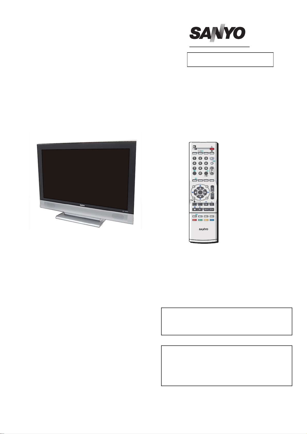
SERVICE MANUAL LCD Television
Model No. LCD-32CA8Z
LCD-37CA8Z
LCD-42CA8Z
(Indonesia,Malaysia,Vietnam,Thailand)
Service Ref.No.LCD-32CA8Z-00
LCD-37CA8Z-00
LCD-42CA8Z-00
3&
79$9 :,'(
-/--
PIP POP
ENTER BACK
OK
BASS
STILL
MENU
TXT/TV
DVD
TIMER
CHANGE
MAIN/SUB
PICTURE
PREV
NEXT
S.SYS SURROUND
SOUND
Contents
Safety Notice................................................2
Specifi cations...............................................3
Chassis Block Diagrams..............................4
CPU Block Diagrams ..................................5
On-screen Service Menu System................6
Service Adjustments.................................7-8
Mechanical Disassembly........................8-14
Chassis Electrical Parts List.................15-35
Printed Wiring Board.............................36-40
Product Code: 32CA8Z:1-130-109-16
37CA8Z:1-130-110-16
42CA8Z:1-130-111-16
Original Version
Chassis Series:UH2-B
Give complete "SERVICE REF. NO." for parts
order or servicing.It is shown on the rating lable
at the cabinet back of the unit.
This T.V. receiver will not work properly in
foreign countries where the television
transmission system and power source
differ from the design specifi cations. Refer
to the specifi cation table.
REFERENCE NO. SM3010271N5JV/N5KV/N5LV
Page 2

Safety Notice
i
Safety Precautions
The following precautions must be observed.
1:Comply with all caution and safety-related notes provided on the cabinet back, cabinet bottom, inside the
cabinet or on the chassis.
2:When replacing a chassis in the cabinet, always be certain that all the protective devices are installed
properly, such as, control knobs, adjustment covers or shields, barriers, etc..
DO NOT OPERATE THIS TELEVISION WITHOUT THE PROTECTIVE SHIELD IN POSITION AND
PROPERLY SECURED
3:Before replacing the cabinet cover, thoroughly inspect the inside of the cabinet to see that no stray parts or
tools have been left inside.
Before returning any televison to the customer, the service personnel must be sure that it is completely safe
to
operate without danger of electrical shock.
Product Safety Notice
Product safety should be considered when a component replacement is made in any area of a
receiver.
Components indicated by mark
which
safety can be of special signifi cance. It is particularly recommended that only parts designated on the parts
list
In this manual be used for component replacement designated by mark
resistance
Wattage or voltage ratings may be made for replacement items designated by mark
in the parts list and the schematic diagram designate components in
. No deviations from
.
2
Page 3

Specifi cations
Maximum Visible Range 32CA8Z:80cm ; 37CA8Z:94cm ; 42CA8Z:107cm (Screen Diagonal Size
Picture Resolution: WXGA 1366(H) x 768(V)
Viewable Angle(Lە /3) L/R ± 89D, U/D ± 89D
Brightness ≥500cd/m²
Contrast LCD-32/37CA8Z: 1200:1 ; LCD-42CA8Z : 1500:1
Definition RF Analog Signals: Horizontal≥350; Vertical≥400
Degree of Color Coverage ≥32%
Mobile Trailer Time ≤20ms
Voltage and Power Consumption
AC100-242V 50/60Hz
32CA8Z:140W; 37CA8Z:158W; 42CA8Z:241W
Power Management VESA DPMS
Colour System PAL/NTSC/NTSC4.43/SECAM
Sound System D/K,I,M,B/G
Channel Coverage VHF
UHF:E2 ~ E12, R1 ~ R12, K1 ~ K9, J1 ~ J12, A2 ~ A13
CATV:S1 ~ S14, X, Y, Z, Z+1, Z+2
Aerial input impedance 75Ω
Speaker Size 6cm x 12cm x 2pcs
Sound speciality Left and Right audio input : Maximum Input Power is 9W
Total Harmonic Distortion(THD)≤10%
Input terminals PC terminal:RGB X 1
HDMI terminal:x1
Video
S-VIDEO input: DIN 4-pin Jack x1
DVD input: Component Y, CB/PB, CR/PR input x 1
Audio input: (R/L)x 4
21 ~ 69, A14 ~ A69, J13 ~ J62
:
:
Audio
Mini stereo jack x 1 (Audio input of PC)
:
Composite video terminals
AV2 Video input is combined with component Y input.
*
x2(1Vp-p,75Ω
)
)
Output terminals
Audio Monitor Output: L/R Stereo Output (RCA jack) x 1 set
Headphone Jack : Mini stereo jack x1
Dimensions(Width x Height x Depth
LCD-32CA8Z: 819mm X 624mm X 271mm
LCD-37CA8Z: 935mm X 695mm X 271mm
LCD-42CA8Z: 1049mm X 758mm X 271mm
Net Weight(Including Stand
LCD-32CA8Z: <14.5KG LCD-37CA8Z: <19.6KG LCD-42CA8Z: <25.4KG
Operating Entironment
Operating Temperature 0ºC~40ºC(32ºF~104ºF
Operating Humidity 20~80%
Storage Temperature -10ºC~50ºC(14ºF~122ºF
Storage Humidity 20~80%
Video Monitor Output: RCA jack x 1
)
)
Including Stand
(
Including Stand
(
Including Stand
(
)
)
)
)
)
3
Page 4
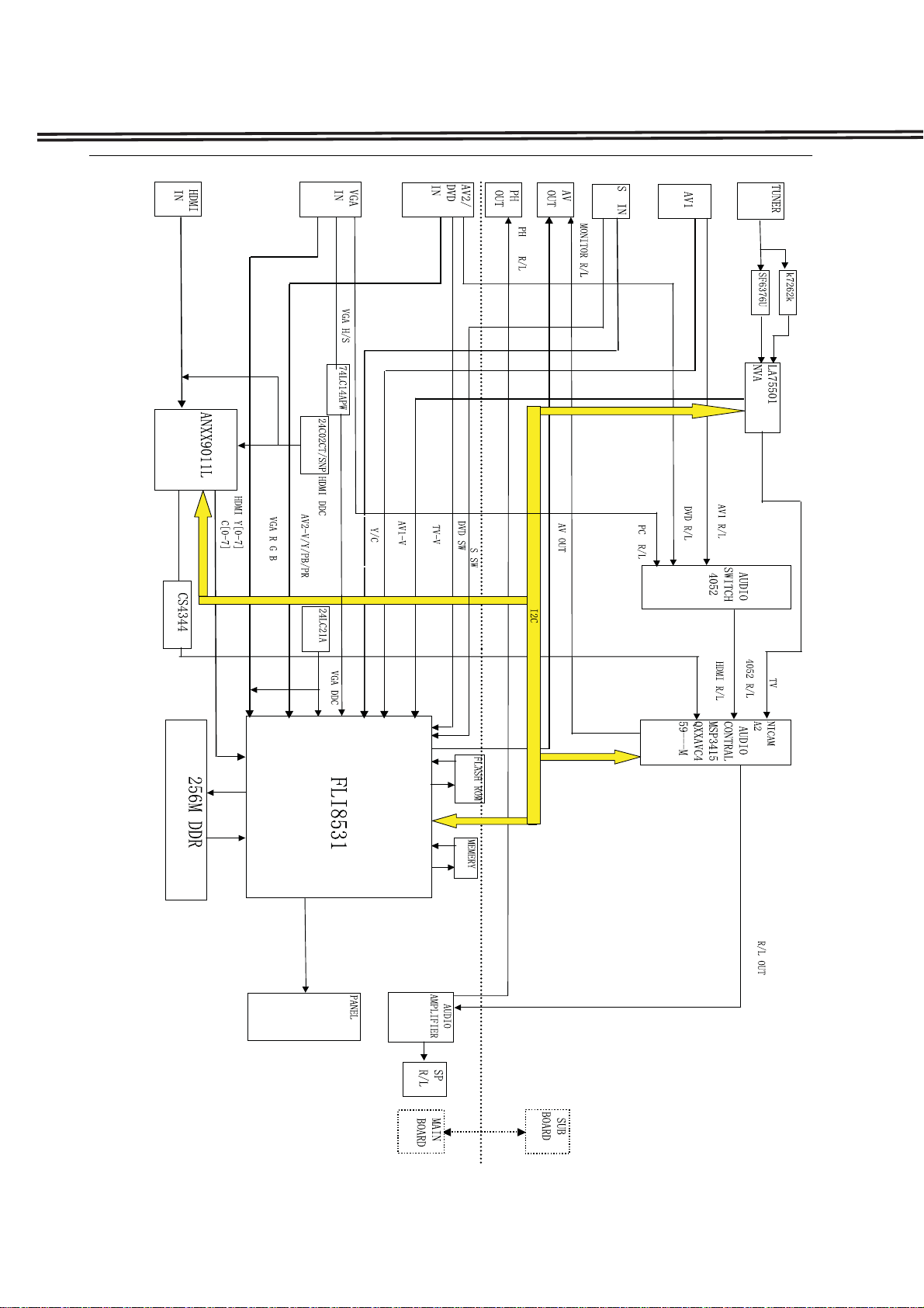
Chassis Block Diagrams
4
Page 5
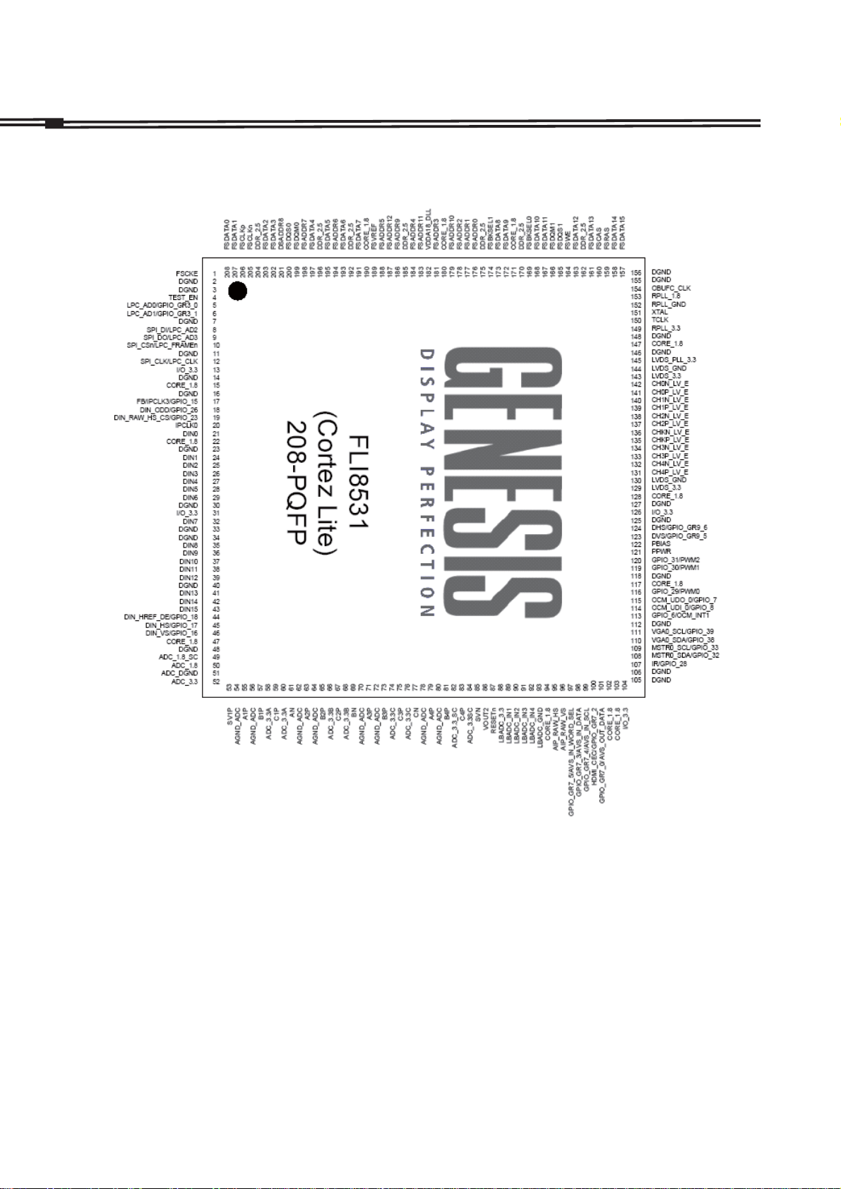
CPU
Block Diagrams
IC7200 QFLI8531-AB-M (FLI8531-ABM)
5
Page 6
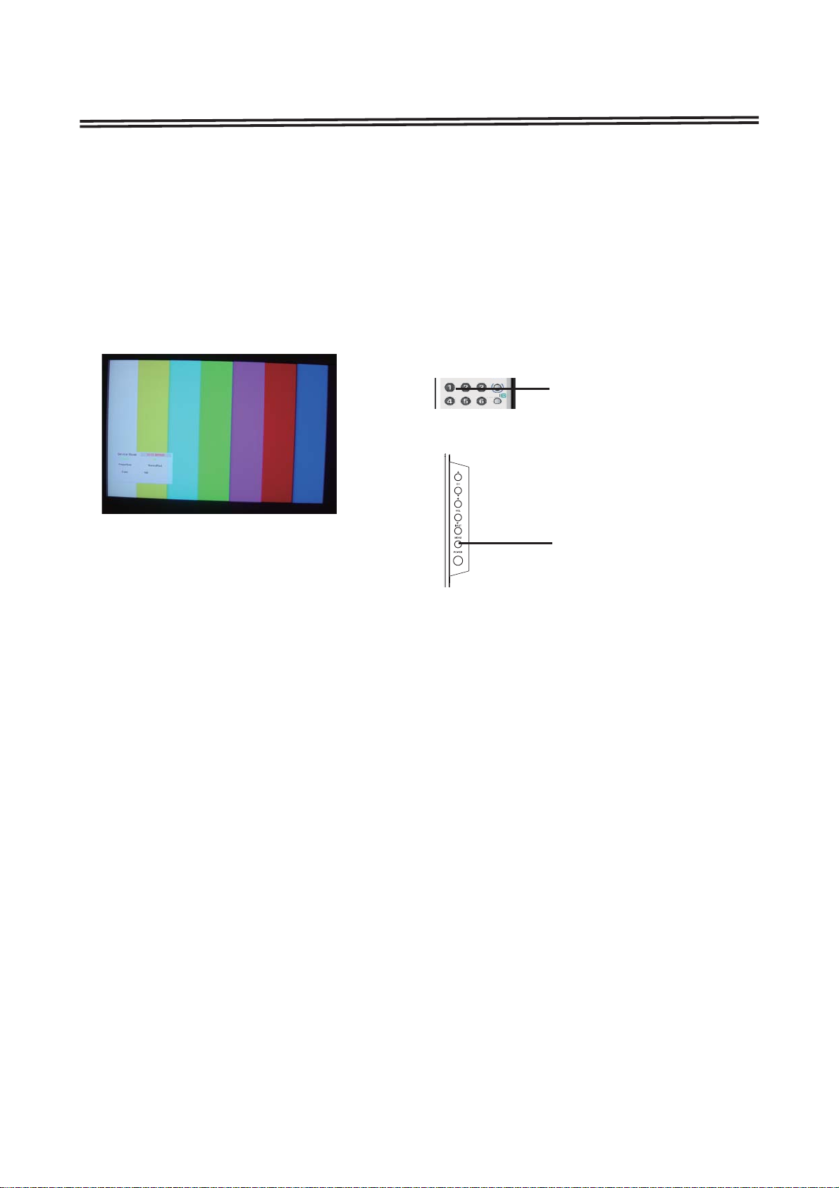
On-screen Service Menu System
General
This set has an On-screen Menu system included in the CPU that allows remote operation for most of the
service adjustments.
On-screen Service Menu System
1) How to enter the Service Menu
1. Press MENU button on SIDE controls, MENU will display.
2. Press and hold MUNE button on SIDE controls and press “1” button on remote controls. SERVICE
MENU will display.
Remote controls
TIMER
DVD
"1"button
SIDE controls
MUNE button
2) How to select the service section and service item and change data value:
To select service section: Press the Cursor ▲or ▼ button on the remote control hand set, and press the OK
button to enter the SUB menu.
To change data value: Select service item by pressing the Cursor ▲or ▼ button , and change data value by
pressing the Cursor ◄or ► button.
3) Exit from the service menu
Press the MENU button repeatedly or turn off the TV set by pressing the POWER ON/OFF button.
6
Page 7

Service Adjustments
Important Notice:
Do not attempt to adjust service adjustments not listed below otherwise it may cause loss of performance
and for correct operation.
White Balance Adjustment
How to adjust White Balance Adjustment
1. Input a white pattern(80%) to the composite input terminal.
2. Set the television to following conditions:
Picture mode: standard
Colour temperature: normal
Pre-heading time: more than 10 minutes
3. Enter the service mode, and select item 291with ▲ or ▼ key.
Select RGB with ▲ or ▼ key.
Press ◄► to adjust the value of RGB until the white balance R, G,B is all 85h.
3. After adjustment, confi rm white balance again by normal picture.
ADC Adjustment
Note:
Because White Balance Adjustment will be changed when adjusting ADC. After adjusting ADC, please reset
White Balance Adjustment.
How to adjust ADC
1.Recive 100% COLOUR BAR from AV1.
2. Enter to SERVICE MODE.
3. Remove the cursor from [Source] to [Properties]. And then select "ADC Calibration", press OK button.
4. Wait for about 15 seconds until the adjustment is fi nished. Then press MENU button to exit.
7
Page 8
Service Adjustments
VCO Adjustment
How to adjust VCO
1. Receive PAL color bar pattern.(ANT input level:58dbuv 75ohms terminated)
2. Connect a digital volt meter to VCO level terminal(TP-VCO) and the ground.
3. Adjust T202, until the volt is 3.6±0.2v DC.
AGC Adjustment
How to adjust AGC
1. Receive PAL color bar pattern.(ANT input level:58dbuv 75ohms terminated)
2. Connect a digital volt meter to tuner-AGC terminal(TP-A) and the ground.
3. Adjust the variable resistance VR202, until the volt is 3.2±0.2v DC.
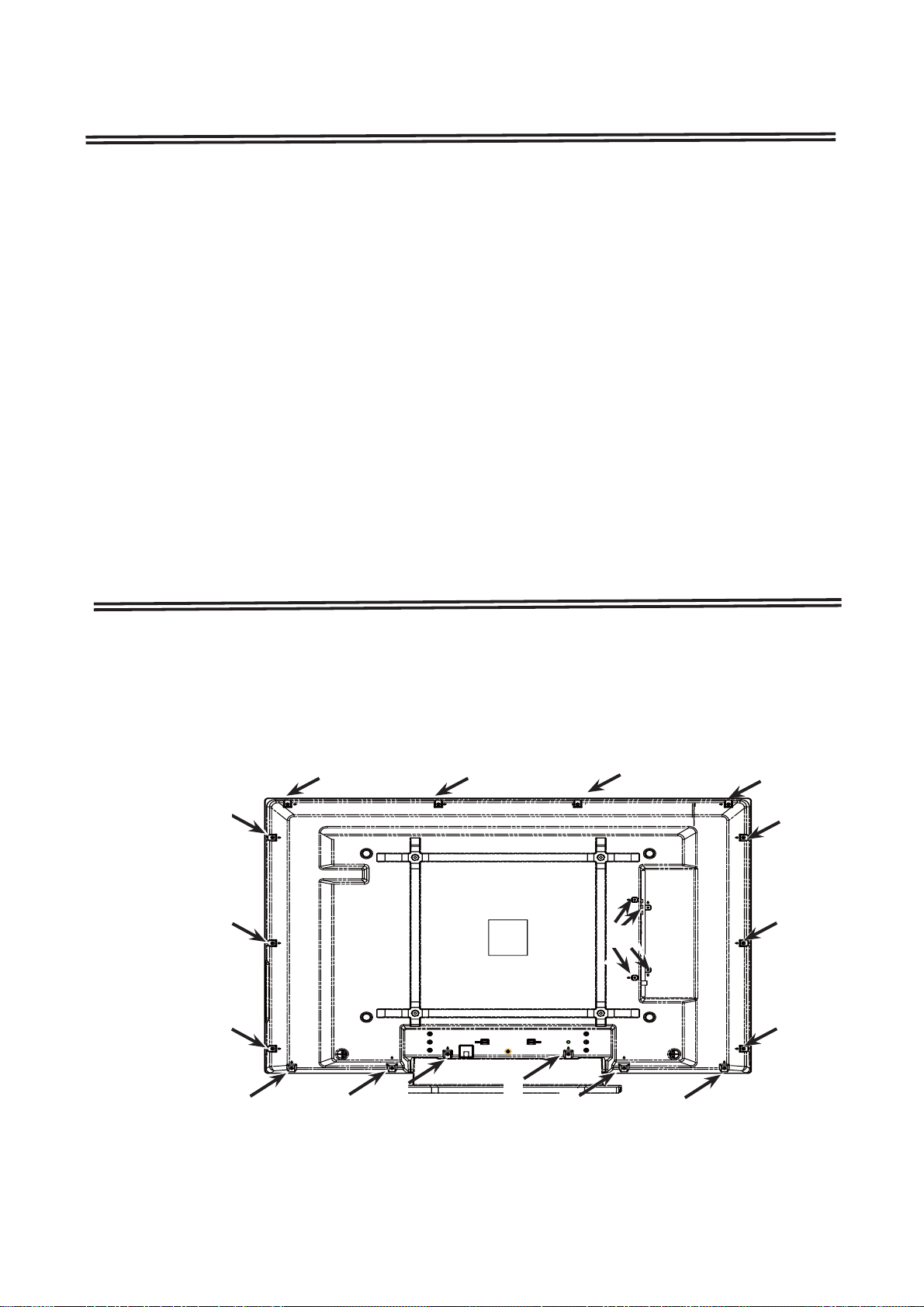
Mechanical Disassembly(LCD-42CA8Z)
(一)Cabinet Back Removal
1.Remove screws A,B.
2.Take the Cabinet Back off.
(A:16pcs,B:4pcs)
AA
A
A
A
A
B
A
A
A
A
A
8
A A
A
A
A
图1
Page 9

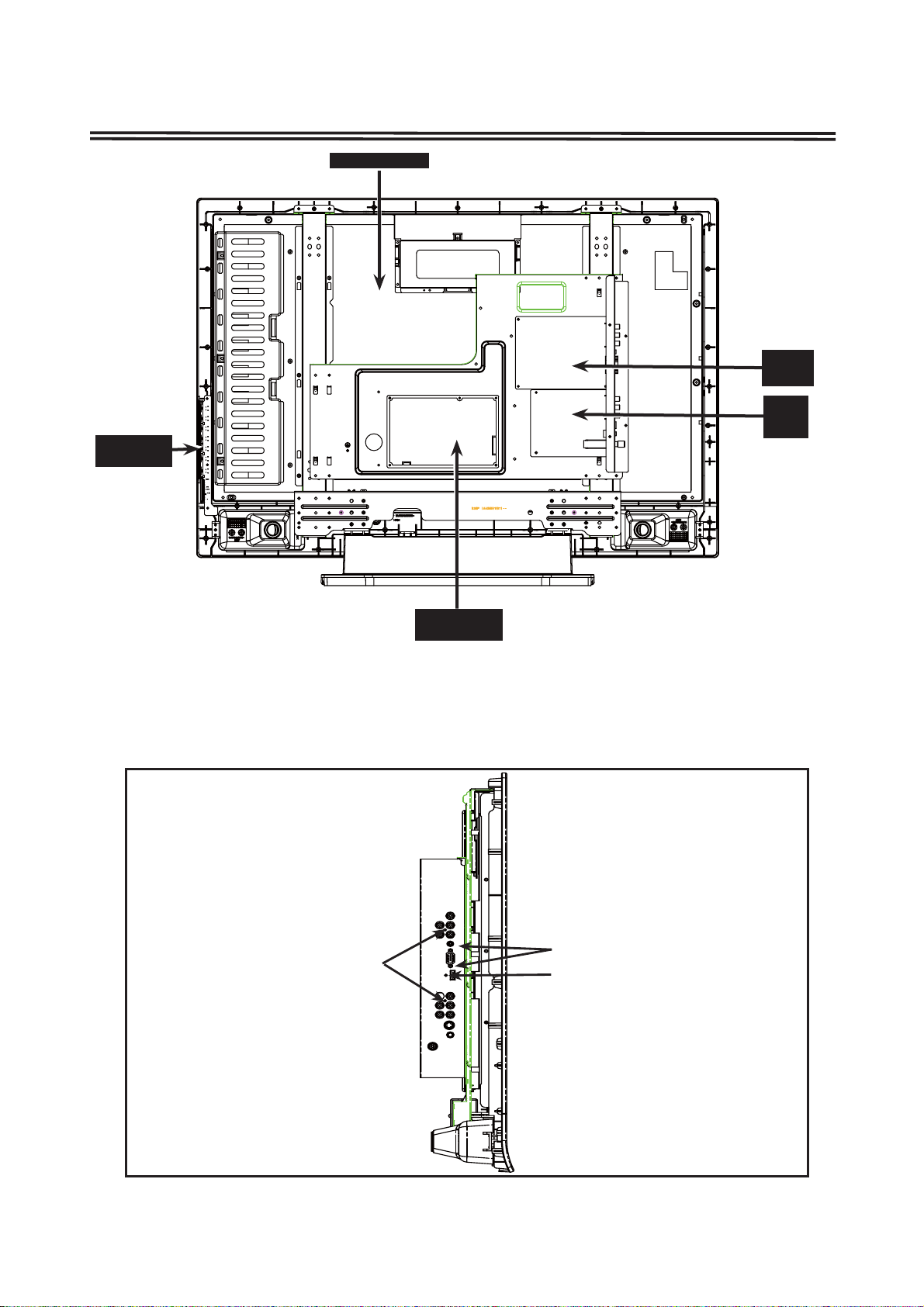
Mechanical Disassembly(LCD-42CA8Z)
LCD SCREEM
KEY&LED
BOARDS
Power board
main
board
SUB
board
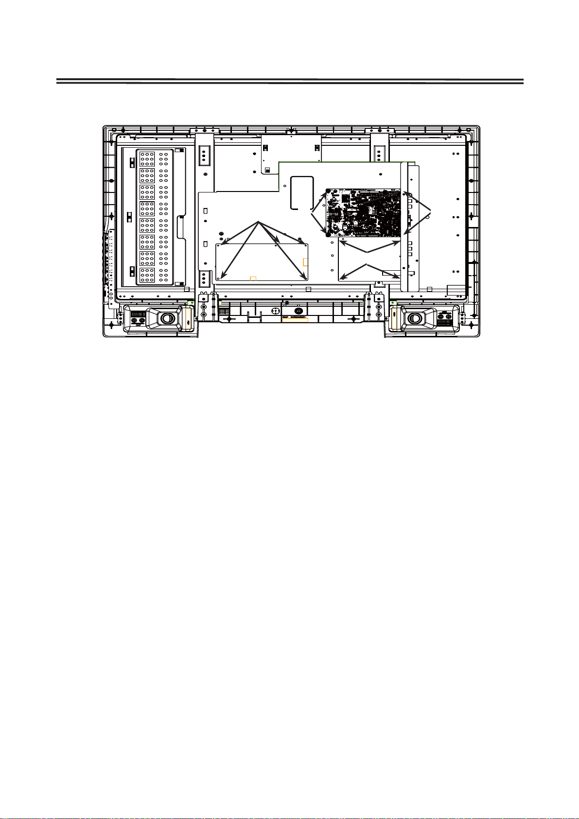
(二)Chassis and Terminal Board Removal
1. Remove screws C , D and F, take the terminal board off.
2. Remove Screw E,take P Board off.
C: 1pcs, D: 2pcs, E:15pcs, F:2pcs)
(
F
D
C
9
Page 10
Mechanical Disassembly(LCD-42CA8Z)
E
E
E
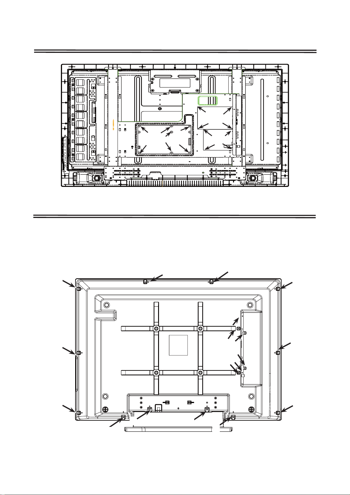
Mechanical Disassembly(LCD-37CA8Z)
(一)Cabinet Back Removal
1.Remove screws A,B.
2.Take the Cabinet Back off.
(A:12pcs,B:6pcs)
A
A
A
A
10
A
A
A
A
A
B
A
A
A
Page 11
Mechanical Disassembly(LCD-37CA8Z)
LCD SCREEM
KEY & LED
BOARDS
main
board
SUB
board
Power board
(二)Chassis and Terminal Board Removal
1. Remove screws C , D and F, take the terminal board off.
2. Remove Screw E,take P Board off.
C: 1pcs, D: 2pcs, E:15pcs, F:2pcs)
(
F
D
C
11
Page 12

Mechanical Disassembly(LCD-37CA8Z)
E
E
E
Mechanical Disassembly(LCD-32CA8Z)
(一)Cabinet Back Removal
1. Remove screws A,B.
2.Take the Cabinet Back off.
(A:9pcs,B:4pcs)
A
A
A
B
A
A
A
12
A
A
A
Page 13

Mechanical Disassembly(LCD-32CA8Z)
LCD Screen
Main board
Button&
Boards
LED
Power board
(二)Chassis and Terminal Board Removal
1. Remove screws C , D and F, take the terminal board off.
2. Remove Screw E,take P Board off.
C: 1pcs, D: 2pcs, E:15pcs, F:2pcs)
(
SUB board
F
D
C
13
Page 14
Mechanical Disassembly(LCD-32CA8Z)
E
E
E
E
14
Page 15
!
!
Chassis Electrical Parts List
!
Product safety should be considered when a component replacement is made in any area of a receiver.
Components indicated by a mark in this parts list and the circuit diagram show components whose value have
special significance to product safety. It is particularly recommended that only parts specified on the following parts
list be used for components replacement pointed out by the mark.
Note: Parts order must contain Service Ref. No., Part No., and descriptions. The main PCB unit will be supplied without tuner and
flyback transformer. They should be ordered separately.
Ref. No. Part No. Description Ref. No. Part No. Description
N5JV
NOTES:
Read description in the Capacitor and Resistor as follows:
CAPACITOR
CERAMIC 100P K 50V
Rated Voltage
Tolerance Symbols:
Less than 10pF
A : Not specified B : ±0.1pF C : ±0.25pF
D : ±0.5pF F : ±1PF G : ±2pF
R : ±0.25-0pF S : ±0-0.25pF E : +0-1pF
More than 10pF
A : Not specified B : ±0.1% C : ±0.25%
D : ±0.5% F : ±1% G : ±2%
H : ±3% J : ±5% K : ±10%
L : ±15% M : ±20% N : ±30%
P : +100-0% Q : +30-10% T : +50-10%
U : +75-10% V : +20-10% W : +100-10%
X : +40-20% Y : +150-10% Z : +80-20%
Rated value: P=pico farad, U=micro farad
Material:
CERAMIC........... Ceramic
MT-PAPER......... Metallized Paper
POLYESTER...... Polyester
MT-POLYEST.....Metallized Polyester
POLYPRO.......... Polypropylene
MT-POLYPRO.... Metallized Polypropylene
COMPO FILM..... Composite film
MT-COMPO........ Metallized Composite
STYRENE........... Styrene
TA-SOLID........... Tantalum Solid
AL-SOLID........... Aluminium Solid
ELECT................ Electrolytic
NP-ELECT.......... Non-polarised Electrolytic
OS-SOLID.......... Aluminium Solid with Organic Semiconductive Electrolytic
DL-ELECT.......... Double Layered Electrolytic
RESISTOR
CARBON 4.7K J A 1/4W
Rated Wattage
Performance Symbols:
A: General B: Non flammable Z: Low noise
Other: Temperature coefficient
Tolerance Symbols:
A: ±0.05% B: ±0.1% C: ±0.25% D: ±0.5%
F: ±1% G: ±2% J: ±5% K: ±10%
M: ±20% P: +5-15%
Rated value, ohms:
K: 1,000, M: 1,000,000
Material:
CARBON........... Carbon
MT-FILM............ Metal Film
OXIDE-MT......... Oxide Metal Film
SOLID................ Composition
MT-GLAZE......... Metal Glaze
WIRE WOUND... Wire Wound
CERAMIC RES.. Ceramic
FUSIBLE RES.... Fusible
OUT OF CIRCUIT BOARD
LCD PANEL
EL901 6450953774 LCD(T315XW02 VC01)
MISCELLANEOUS
WPOW-404 6520022935 CORD,ID-CONNECTOR
W7205 6520023086 CORD 30PIN (LVDS)
W901 6450940347 CORD,POWER-2.41MK-VAR-2
W901A 6520015470 CORE,PIPE
WCNA 6520015470 CORE,PIPE
W101-10A 6520019041 CORE,CLAMP
SP901 6520014473 SPEAKER,8
6520018327 SPEAKER,8
SP902 6520014473 SPEAKER,8
6520018327 SPEAKER,8
U100 6520024298 UNIT,POWER
6103351605 ASSY,SUB-COMP N5JV
1AA0B10S25800
TRANSISTOR
Q103 4060214407 TR MMBTSC3928R
4050144519 TR 2SC2412K T146 R
4050144618 TR 2SC2412K T146 S
4050158724 TR 2SC2812-L6-TB
4050158922 TR 2SC2812-L7-TB
4051631612 TR 2SC2812N-L6-TB0
4051739813 TR 2SC3928A1R
4051739912 TR 2SC3928A1S
Q200 4060214407 TR MMBTSC3928R
4050144519 TR 2SC2412K T146 R
4050144618 TR 2SC2412K T146 S
4050158724 TR 2SC2812-L6-TB
4050158922 TR 2SC2812-L7-TB
4051631612 TR 2SC2812N-L6-TB0
4051739813 TR 2SC3928A1R
4051739912 TR 2SC3928A1S
Q201 4050159721 TR 2SC2814-F4-TB
Q202 4050159721 TR 2SC2814-F4-TB
Q209 4060214308 TR MMBTSA1235F
4051345925 TR 2SA1037AK-T146-R
4051472215 TR 2SA1037AK-S-T146
4050020318 TR 2SA1037K T146 R
4050020417 TR 2SA1037K T146 S
4050026726 TR 2SA1179-M6-TB
4050026924 TR 2SA1179-M7-TB
4051631513 TR 2SA1179N-M6-TB
4051739615 TR 2SA1235A1E
4051739714 TR 2SA1235A1F
Q210 4060214407 TR MMBTSC3928R
4050144519 TR 2SC2412K T146 R
4050144618 TR 2SC2412K T146 S
4050158724 TR 2SC2812-L6-TB
4050158922 TR 2SC2812-L7-TB
4051631612 TR 2SC2812N-L6-TB0
-15-
Page 16

Ref. No. Part No. Description Ref. No. Part No. Description
N5JV
4051739813 TR 2SC3928A1R
4051739912 TR 2SC3928A1S
Q300 4060214407 TR MMBTSC3928R
4050144519 TR 2SC2412K T146 R
4050144618 TR 2SC2412K T146 S
4050158724 TR 2SC2812-L6-TB
4050158922 TR 2SC2812-L7-TB
4051631612 TR 2SC2812N-L6-TB0
4051739813 TR 2SC3928A1R
4051739912 TR 2SC3928A1S
Q301 4060214407 TR MMBTSC3928R
4050144519 TR 2SC2412K T146 R
4050144618 TR 2SC2412K T146 S
4050158724 TR 2SC2812-L6-TB
4050158922 TR 2SC2812-L7-TB
4051631612 TR 2SC2812N-L6-TB0
4051739813 TR 2SC3928A1R
4051739912 TR 2SC3928A1S
Q307 4060214407 TR MMBTSC3928R
4050144519 TR 2SC2412K T146 R
4050144618 TR 2SC2412K T146 S
4050158724 TR 2SC2812-L6-TB
4050158922 TR 2SC2812-L7-TB
4051631612 TR 2SC2812N-L6-TB0
4051739813 TR 2SC3928A1R
4051739912 TR 2SC3928A1S
Q308 4060214407 TR MMBTSC3928R
4050144519 TR 2SC2412K T146 R
4050144618 TR 2SC2412K T146 S
4050158724 TR 2SC2812-L6-TB
4050158922 TR 2SC2812-L7-TB
4051631612 TR 2SC2812N-L6-TB0
4051739813 TR 2SC3928A1R
4051739912 TR 2SC3928A1S
Q400 4052110017 TR 2SC5730-Q
4052109912 TR 2SC5730-R
4052027711 TR TPC8109
Q601 4060214407 TR MMBTSC3928R
4050144519 TR 2SC2412K T146 R
4050144618 TR 2SC2412K T146 S
4050158724 TR 2SC2812-L6-TB
4050158922 TR 2SC2812-L7-TB
4051631612 TR 2SC2812N-L6-TB0
4051739813 TR 2SC3928A1R
4051739912 TR 2SC3928A1S
INTEGRATED CIRCUIT
IC201 4096883618 IC LA75503V-TLM-E
IC401 4094976312 IC BA09FP-E2
IC402 4090512722 IC TC4052BF(EL)
IC404 4094166515 IC BA05FP-E2
IC405 4105200105 IC MSP3415G-QA-B8-V3
CAPACITOR
C101 4041126200 ELECT 47U M 25V
4040989202 ELECT 47U M 25V
C104 4041129904 ELECT 220U M 16V
4040972006 ELECT 220U M 16V
C105 4040901204 CERAMIC 0.01U K 50V
C108 4041128402 ELECT 22U M 50V
4040973201 ELECT 22U M 50V
C109 4040954903 CERAMIC 0.033U Z 50V
C110 4040954200 CERAMIC 0.01U Z 50V
C111 4040954200 CERAMIC 0.01U Z 50V
C112 4040954200 CERAMIC 0.01U Z 50V
C114 4041130801 ELECT 100U M 16V
4040971801 ELECT 100U M 16V
C115 4041034505 CERAMIC 0.1U K 16V
4040950509 CERAMIC 0.1U K 16V
4032989619 CERAMIC 0.1U K 16V
C118 4041130801 ELECT 100U M 16V
4040971801 ELECT 100U M 16V
C119 4041034505 CERAMIC 0.1U K 16V
4040950509 CERAMIC 0.1U K 16V
4032989619 CERAMIC 0.1U K 16V
C201 4040901204 CERAMIC 0.01U K 50V
C202 4041032402 CERAMIC 1000P K 50V
4040901105 CERAMIC 1000P K 50V
C203 4040901204 CERAMIC 0.01U K 50V
C204 4041130801 ELECT 100U M 16V
4040971801 ELECT 100U M 16V
C205 4040944003 CERAMIC 0.1U Z 50V
C206 4040944003 CERAMIC 0.1U Z 50V
C208 4040954200 CERAMIC 0.01U Z 50V
C210 4040954200 CERAMIC 0.01U Z 50V
C211 4041143108 ELECT 0.47U M 50V
4040972808 ELECT 0.47U M 50V
C212 4040954200 CERAMIC 0.01U Z 50V
C213 4041036400 CERAMIC 0.022U K 16V
4040952503 CERAMIC 0.022U K 16V
4031669512 CERAMIC 0.022U K 16V
C215 4040954200 CERAMIC 0.01U Z 50V
C217 4041036400 CERAMIC 0.022U K 16V
4040952503 CERAMIC 0.022U K 16V
4031669512 CERAMIC 0.022U K 16V
C220 4041079605 ELECT 1U M 50V
4040970101 ELECT 1U M 50V
C222 4041128600 ELECT 10U M 16V
4040969600 ELECT 10U M 16V
C224 4041079605 ELECT 1U M 50V
4040970101 ELECT 1U M 50V
C225 4040901204 CERAMIC 0.01U K 50V
C227 4041128600 ELECT 10U M 16V
4040969600 ELECT 10U M 16V
C230 4041034505 CERAMIC 0.1U K 16V
4040950509 CERAMIC 0.1U K 16V
4032989619 CERAMIC 0.1U K 16V
C232 4041143108 ELECT 0.47U M 50V
4040972808 ELECT 0.47U M 50V
C239 4041128600 ELECT 10U M 16V
4040969600 ELECT 10U M 16V
C240 4032070317 CERAMIC 1U Z 16V
4032789615 CERAMIC 1U Z 16V
C245 4040954200 CERAMIC 0.01U Z 50V
C300 4041142309 ELECT 10U M 25V
4040988809 ELECT 10U M 25V
4040854401 ELECT 10U M 25V
C302 4041142309 ELECT 10U M 25V
4040988809 ELECT 10U M 25V
4040854401 ELECT 10U M 25V
C303 4041142309 ELECT 10U M 25V
4040988809 ELECT 10U M 25V
4040854401 ELECT 10U M 25V
C304 4041142309 ELECT 10U M 25V
4040988809 ELECT 10U M 25V
4040854401 ELECT 10U M 25V
C305 4041142309 ELECT 10U M 25V
4040988809 ELECT 10U M 25V
4040854401 ELECT 10U M 25V
C307 4041142309 ELECT 10U M 25V
4040988809 ELECT 10U M 25V
4040854401 ELECT 10U M 25V
C308 4041044900 CERAMIC 0.1U K 50V
-16-
Page 17

Ref. No. Part No. Description Ref. No. Part No. Description
N5JV
4040912606 CERAMIC 0.1U K 50V
4033670417 CERAMIC 0.1U K 50V
C309 4041129300 ELECT 470U M 16V
4040988700 ELECT 470U M 16V
C310 4041130801 ELECT 100U M 16V
4040971801 ELECT 100U M 16V
C311 4041130801 ELECT 100U M 16V
4040971801 ELECT 100U M 16V
C350 4040949800 CERAMIC 0.1U Z 25V
4031640214 CERAMIC 0.1U Z 25V
C351 4041130801 ELECT 100U M 16V
4040971801 ELECT 100U M 16V
C352 4040949800 CERAMIC 0.1U Z 25V
4031640214 CERAMIC 0.1U Z 25V
C353 4041142606 ELECT 4.7U M 25V
4041055005 ELECT 4.7U M 25V
4040916604 ELECT 4.7U M 25V
C354 4041142606 ELECT 4.7U M 25V
4041055005 ELECT 4.7U M 25V
4040916604 ELECT 4.7U M 25V
C355 4041130801 ELECT 100U M 16V
4040971801 ELECT 100U M 16V
C356 4040973003 ELECT 2.2U M 50V
C357 4040954200 CERAMIC 0.01U Z 50V
C358 4041142606 ELECT 4.7U M 25V
4041055005 ELECT 4.7U M 25V
4040916604 ELECT 4.7U M 25V
C359 4041142606 ELECT 4.7U M 25V
4041055005 ELECT 4.7U M 25V
4040916604 ELECT 4.7U M 25V
C360 4041142606 ELECT 4.7U M 25V
4041055005 ELECT 4.7U M 25V
4040916604 ELECT 4.7U M 25V
C361 4041142606 ELECT 4.7U M 25V
4041055005 ELECT 4.7U M 25V
4040916604 ELECT 4.7U M 25V
C362 4041142606 ELECT 4.7U M 25V
4041055005 ELECT 4.7U M 25V
4040916604 ELECT 4.7U M 25V
C363 4040949800 CERAMIC 0.1U Z 25V
4031640214 CERAMIC 0.1U Z 25V
C364 4041130801 ELECT 100U M 16V
4040971801 ELECT 100U M 16V
C365 4040949800 CERAMIC 0.1U Z 25V
4031640214 CERAMIC 0.1U Z 25V
C366 4041130801 ELECT 100U M 16V
4040971801 ELECT 100U M 16V
C367 4040945307 CERAMIC 6P D 50V
4031571617 CERAMIC 6P D 50V
C368 4040945307 CERAMIC 6P D 50V
4031571617 CERAMIC 6P D 50V
C370 4040946403 CERAMIC 100P J 50V
C371 4040948902 CERAMIC 56P J 50V
4031573116 CERAMIC 56P J 50V
C374 4040954200 CERAMIC 0.01U Z 50V
C375 4041044900 CERAMIC 0.1U K 50V
4040912606 CERAMIC 0.1U K 50V
4033670417 CERAMIC 0.1U K 50V
C376 4041130801 ELECT 100U M 16V
4040971801 ELECT 100U M 16V
C377 4040948902 CERAMIC 56P J 50V
4031573116 CERAMIC 56P J 50V
C400 4041130801 ELECT 100U M 16V
4040971801 ELECT 100U M 16V
C402 4041034505 CERAMIC 0.1U K 16V
4040950509 CERAMIC 0.1U K 16V
4032989619 CERAMIC 0.1U K 16V
C403 4041130801 ELECT 100U M 16V
4040971801 ELECT 100U M 16V
C405 4041034505 CERAMIC 0.1U K 16V
4040950509 CERAMIC 0.1U K 16V
4032989619 CERAMIC 0.1U K 16V
C406 4041130801 ELECT 100U M 16V
4040971801 ELECT 100U M 16V
C408 4041034505 CERAMIC 0.1U K 16V
4040950509 CERAMIC 0.1U K 16V
4032989619 CERAMIC 0.1U K 16V
C409 4041131501 ELECT 1000U M 16V
4040969709 ELECT 1000U M 16V
C410 4041034505 CERAMIC 0.1U K 16V
4040950509 CERAMIC 0.1U K 16V
4032989619 CERAMIC 0.1U K 16V
C411 4041130801 ELECT 100U M 16V
4040971801 ELECT 100U M 16V
C412 4041034505 CERAMIC 0.1U K 16V
4040950509 CERAMIC 0.1U K 16V
4032989619 CERAMIC 0.1U K 16V
C413 4041034505 CERAMIC 0.1U K 16V
4040950509 CERAMIC 0.1U K 16V
4032989619 CERAMIC 0.1U K 16V
C414 4041128600 ELECT 10U M 16V
4040969600 ELECT 10U M 16V
C415 4041046607 CERAMIC 4700P K 50V
4040914402 CERAMIC 4700P K 50V
4031552319 CERAMIC 4700P K 50V
C416 4041046607 CERAMIC 4700P K 50V
4040914402 CERAMIC 4700P K 50V
4031552319 CERAMIC 4700P K 50V
C417 4041043507 CERAMIC 270P J 50V
4040947905 CERAMIC 270P J 50V
4031726116 CERAMIC 270P J 50V
C418 4041046607 CERAMIC 4700P K 50V
4040914402 CERAMIC 4700P K 50V
4031552319 CERAMIC 4700P K 50V
C419 4041034505 CERAMIC 0.1U K 16V
4040950509 CERAMIC 0.1U K 16V
4032989619 CERAMIC 0.1U K 16V
C420 4040954903 CERAMIC 0.033U Z 50V
4032246811 CERAMIC 0.033U Z 50V
C422 4040954903 CERAMIC 0.033U Z 50V
4032246811 CERAMIC 0.033U Z 50V
C423 4040912606 CERAMIC 0.1U K 50V
C424 4041128402 ELECT 22U M 50V
4040973201 ELECT 22U M 50V
C602 4041129300 ELECT 470U M 16V
4040988700 ELECT 470U M 16V
C603 4041034505 CERAMIC 0.1U K 16V
4040950509 CERAMIC 0.1U K 16V
4032989619 CERAMIC 0.1U K 16V
C606 4032991612 CERAMIC 1U K 16V
C607 4032991612 CERAMIC 1U K 16V
C608 4040913900 CERAMIC 3300P K 50V
4031552210 CERAMIC 3300P K 50V
C609 4040913900 CERAMIC 3300P K 50V
4031552210 CERAMIC 3300P K 50V
RESISTOR
R018 4011506011 MT-GLAZE 0.000 ZA 1/10W
R019 4011506011 MT-GLAZE 0.000 ZA 1/10W
R100 4012559719 MT-GLAZE 82K JA 1/10W
R101 4012566915 MT-GLAZE 680 JA 1/10W
R102 4012566915 MT-GLAZE 680 JA 1/10W
R103 4011506011 MT-GLAZE 0.000 ZA 1/10W
R104 4011624111 MT-GLAZE 5.6K JA 1/10W
-17-
Page 18

Ref. No. Part No. Description Ref. No. Part No. Description
N5JV
R105 4011506219 MT-GLAZE 1K JA 1/10W
R106 4011523216 MT-GLAZE 330 JA 1/10W
R107 4012563617 MT-GLAZE 15K JA 1/10W
R108 4012567318 MT-GLAZE 6.8K JA 1/10W
R109 4011505915 MT-GLAZE 10K JA 1/10W
R110 4011506110 MT-GLAZE 2.2K JA 1/10W
R111 4012566311 MT-GLAZE 47K JA 1/10W
R120 4012564119 MT-GLAZE 56 JA 1/10W
R200 4012556411 MT-GLAZE 3K JA 1/10W
R205 4011505915 MT-GLAZE 10K JA 1/10W
R210 4011505915 MT-GLAZE 10K JA 1/10W
R213 4012564119 MT-GLAZE 56 JA 1/10W
R214 4012567516 MT-GLAZE 390 JA 1/10W
R215 4011623015 MT-GLAZE 22K JA 1/10W
R218 4011506011 MT-GLAZE 0.000 ZA 1/10W
R219 4011506011 MT-GLAZE 0.000 ZA 1/10W
R220 4011623718 MT-GLAZE 4.7K JA 1/10W
R222 4011505915 MT-GLAZE 10K JA 1/10W
R223 4011505915 MT-GLAZE 10K JA 1/10W
R224 4011506219 MT-GLAZE 1K JA 1/10W
R226 4012559511 MT-GLAZE 220K JA 1/10W
R227 4012564119 MT-GLAZE 56 JA 1/10W
R230 4011523216 MT-GLAZE 330 JA 1/10W
R233 4011506011 MT-GLAZE 0.000 ZA 1/10W
R236 4011623114 MT-GLAZE 3.3K JA 1/10W
R240 4011624012 MT-GLAZE 560 JA 1/10W
R242 4011506011 MT-GLAZE 0.000 ZA 1/10W
R243 4011506011 MT-GLAZE 0.000 ZA 1/10W
R246 4011506219 MT-GLAZE 1K JA 1/10W
R248 4012564119 MT-GLAZE 56 JA 1/10W
R281 4011506011 MT-GLAZE 0.000 ZA 1/10W
R301 4011506219 MT-GLAZE 1K JA 1/10W
R302 4011505816 MT-GLAZE 100K JA 1/10W
R304 4011623411 MT-GLAZE 39K JA 1/10W
R305 4011505816 MT-GLAZE 100K JA 1/10W
R306 4011623411 MT-GLAZE 39K JA 1/10W
R307 4011506219 MT-GLAZE 1K JA 1/10W
R308 4011623411 MT-GLAZE 39K JA 1/10W
R309 4012566311 MT-GLAZE 47K JA 1/10W
R310 4012556510 MT-GLAZE 100 JA 1/10W
R311 4012566311 MT-GLAZE 47K JA 1/10W
R312 4012556510 MT-GLAZE 100 JA 1/10W
R313 4011505816 MT-GLAZE 100K JA 1/10W
R314 4011623411 MT-GLAZE 39K JA 1/10W
R315 4011505816 MT-GLAZE 100K JA 1/10W
R316 4011623411 MT-GLAZE 39K JA 1/10W
R317 4011505816 MT-GLAZE 100K JA 1/10W
R318 4011506219 MT-GLAZE 1K JA 1/10W
R319 4011506219 MT-GLAZE 1K JA 1/10W
R320 4011505816 MT-GLAZE 100K JA 1/10W
R321 4011623411 MT-GLAZE 39K JA 1/10W
R329 4011624111 MT-GLAZE 5.6K JA 1/10W
R350 4012556510 MT-GLAZE 100 JA 1/10W
R351 4011506011 MT-GLAZE 0.000 ZA 1/10W
R352 4011506011 MT-GLAZE 0.000 ZA 1/10W
R353 4011505816 MT-GLAZE 100K JA 1/10W
R354 4011505816 MT-GLAZE 100K JA 1/10W
R355 4011506011 MT-GLAZE 0.000 ZA 1/10W
R356 4011505816 MT-GLAZE 100K JA 1/10W
R357 4011506011 MT-GLAZE 0.000 ZA 1/10W
R358 4011506011 MT-GLAZE 0.000 ZA 1/10W
R359 4011624111 MT-GLAZE 5.6K JA 1/10W
R360 4011505816 MT-GLAZE 100K JA 1/10W
R361 4011506011 MT-GLAZE 0.000 ZA 1/10W
R362 4012556510 MT-GLAZE 100 JA 1/10W
4020902306 MT-GLAZE 100 JA 1/16W
R363 4012556510 MT-GLAZE 100 JA 1/10W
4020902306 MT-GLAZE 100 JA 1/16W
R364 4012589914 MT-GLAZE 10 JA 1/3W
R365 4011506219 MT-GLAZE 1K JA 1/10W
R380 4011506110 MT-GLAZE 2.2K JA 1/10W
R381 4011506110 MT-GLAZE 2.2K JA 1/10W
R401 4021097803 OXIDE-MT 15 JA 1W
4020927002 OXIDE-MT 15 JA 1W
4020859204 OXIDE-MT 15 JA 1W
4010591602 OXIDE-MT 15 JA 1W
R402 4012558712 MT-GLAZE 22 JA 1/10W
R403 4012565611 MT-GLAZE 47 JA 1/10W
R404 4011623015 MT-GLAZE 22K JA 1/10W
R405 4012561712 MT-GLAZE 33K JA 1/10W
R406 4011624111 MT-GLAZE 5.6K JA 1/10W
R407 4011624111 MT-GLAZE 5.6K JA 1/10W
R408 4012566311 MT-GLAZE 47K JA 1/10W
R409 4012566311 MT-GLAZE 47K JA 1/10W
R410 4021097407 OXIDE-MT 2.2 JA 1W
4020849601 OXIDE-MT 2.2 JA 1W
R500 4011505816 MT-GLAZE 100K JA 1/10W
R501 4011506011 MT-GLAZE 0.000 ZA 1/10W
R502 4011505816 MT-GLAZE 100K JA 1/10W
R504 4011505816 MT-GLAZE 100K JA 1/10W
R505 4011506011 MT-GLAZE 0.000 ZA 1/10W
R506 4011505816 MT-GLAZE 100K JA 1/10W
R507 4011506011 MT-GLAZE 0.000 ZA 1/10W
R508 4011505816 MT-GLAZE 100K JA 1/10W
R509 4011506011 MT-GLAZE 0.000 ZA 1/10W
R510 4011505816 MT-GLAZE 100K JA 1/10W
R511 4011506011 MT-GLAZE 0.000 ZA 1/10W
R514 4011506011 MT-GLAZE 0.000 ZA 1/10W
R516 4011623817 MT-GLAZE 470K JA 1/10W
R519 4011623817 MT-GLAZE 470K JA 1/10W
R600 4012764717 MT-GLAZE 0.000 ZA 1/3W
R602 4011505915 MT-GLAZE 10K JA 1/10W
R604 4011623718 MT-GLAZE 4.7K JA 1/10W
R605 4012567318 MT-GLAZE 6.8K JA 1/10W
VARIABLE RESISTOR
VR202 6450065521 VR,SEMI,22K N
COIL
L100 6450806827 INDUCTOR,3.3U M
L101 6450806827 INDUCTOR,3.3U M
L300 6450806827 INDUCTOR,3.3U M
L301 6450806827 INDUCTOR,3.3U M
L302 6450806827 INDUCTOR,3.3U M
L303 6450591723 INDUCTOR,100U J
L304 6450806827 INDUCTOR,3.3U M
L402 6520023246 INDUCTOR,1MH
L403 6450689024 INDUCTOR,47U K
L404 6450757419 INDUCTOR,390U J
TRANSFORMER
T202 6450338410 TRANS,OSC,38MHZ
DIODA
D104 4080627003 DIODE 1SS356WS
4071661118 DIODE 1SS356-TW11
D300 4080627201 DIODE 1SS35
4071490817 DIODE 1SS355-TE-17
D350 4072105413 DIODE RB551V-30-TE-17
D400 4080627201 DIODE 1SS35
4071490817 DIODE 1SS355-TE-17
D401 4080627201 DIODE 1SS35
4071490817 DIODE 1SS355-TE-17
D402 4080627201 DIODE 1SS35
-18-
Page 19

Ref. No. Part No. Description Ref. No. Part No. Description
N5JV
4071490817 DIODE 1SS355-TE-17
D403 4080627201 DIODE 1SS35
4071490817 DIODE 1SS355-TE-17
D404 4080627201 DIODE 1SS35
4071490817 DIODE 1SS355-TE-17
D405 4080627201 DIODE 1SS35
4071490817 DIODE 1SS355-TE-17
D406 4080627201 DIODE 1SS35
4071490817 DIODE 1SS355-TE-17
D407 4080627201 DIODE 1SS35
4071490817 DIODE 1SS355-TE-17
D600 4080627201 DIODE 1SS35
4071490817 DIODE 1SS355-TE-17
MISCELLANEOUS
A101 6450904059 TUNER, U/V
K500 6520019171 JACK,RCA-6
K501 6520011960 SOCKET,DIN 4P
K502 6100098053 JACK,PHONE D3.6
6520015937 JACK,PHONE D3.6
K600 6520022195 SOCKET,PWB 40P
X201 4220065306 SAW F K9352M
X202 4220065405 SAW F K7262K
X206 6520022348 OSC,CRYSTAL4.000MHZ
X300 6520023895 OSC,CRYSTAL18.432MHZ
ZD1 4072284910 ZENER DIODE UDZS33B-TE-17
ZD1 4080634100 ZENER DIODE MM3Z 33B
6103351537 ASSY,PWB,MAIN N5JV
1AA0B10S25700
TRANSISTOR
Q001 4060214407 TR MMBTSC3928R
4050144519 TR 2SC2412K T146 R
4050144618 TR 2SC2412K T146 S
4050158724 TR 2SC2812-L6-TB
4050158922 TR 2SC2812-L7-TB
4051631612 TR 2SC2812N-L6-TB0
4051739813 TR 2SC3928A1R
4051739912 TR 2SC3928A1S
Q681 4060214407 TR MMBTSC3928R
4050144519 TR 2SC2412K T146 R
4050144618 TR 2SC2412K T146 S
4050158724 TR 2SC2812-L6-TB
4050158922 TR 2SC2812-L7-TB
4051631612 TR 2SC2812N-L6-TB0
4051739813 TR 2SC3928A1R
4051739912 TR 2SC3928A1S
Q7200 4060214407 TR MMBTSC3928R
4050144519 TR 2SC2412K T146 R
4050144618 TR 2SC2412K T146 S
4050158724 TR 2SC2812-L6-TB
4050158922 TR 2SC2812-L7-TB
4051631612 TR 2SC2812N-L6-TB0
4051739813 TR 2SC3928A1R
4051739912 TR 2SC3928A1S
Q7201 4060214308 TR MMBTSA1235F
4051345925 TR 2SA1037AK-T146-R
4051472215 TR 2SA1037AK-S-T146
4050020318 TR 2SA1037K T146 R
4050020417 TR 2SA1037K T146 S
4050026726 TR 2SA1179-M6-TB
4050026924 TR 2SA1179-M7-TB
4051631513 TR 2SA1179N-M6-TB
4051739615 TR 2SA1235A1E
4051739714 TR 2SA1235A1F
Q7203 4060214407 TR MMBTSC3928R
4050144519 TR 2SC2412K T146 R
4050144618 TR 2SC2412K T146 S
4050158724 TR 2SC2812-L6-TB
4050158922 TR 2SC2812-L7-TB
4051631612 TR 2SC2812N-L6-TB0
4051739813 TR 2SC3928A1R
4051739912 TR 2SC3928A1S
Q7280 4052027711 TR TPC8109
Q7500 4060214407 TR MMBTSC3928R
4050144519 TR 2SC2412K T146 R
4050144618 TR 2SC2412K T146 S
4050158724 TR 2SC2812-L6-TB
4050158922 TR 2SC2812-L7-TB
4051631612 TR 2SC2812N-L6-TB0
4051739813 TR 2SC3928A1R
4051739912 TR 2SC3928A1S
Q8002 4060214407 TR MMBTSC3928R
4050144519 TR 2SC2412K T146 R
4050144618 TR 2SC2412K T146 S
4050158724 TR 2SC2812-L6-TB
4050158922 TR 2SC2812-L7-TB
4051631612 TR 2SC2812N-L6-TB0
4051739813 TR 2SC3928A1R
4051739912 TR 2SC3928A1S
Q8003 4050458725 TR 2SK536
Q8004 4050458725 TR 2SK536
Q8007 4060214407 TR MMBTSC3928R
4050144519 TR 2SC2412K T146 R
4050144618 TR 2SC2412K T146 S
4050158724 TR 2SC2812-L6-TB
4050158922 TR 2SC2812-L7-TB
4051631612 TR 2SC2812N-L6-TB0
4051739813 TR 2SC3928A1R
4051739912 TR 2SC3928A1S
Q8100 4060214407 TR MMBTSC3928R
4050144519 TR 2SC2412K T146 R
4050144618 TR 2SC2412K T146 S
4050158724 TR 2SC2812-L6-TB
4050158922 TR 2SC2812-L7-TB
4051631612 TR 2SC2812N-L6-TB0
4051739813 TR 2SC3928A1R
4051739912 TR 2SC3928A1S
Q8102 4060214308 TR MMBTSA1235F
4051345925 TR 2SA1037AK-T146-R
4051472215 TR 2SA1037AK-S-T146
4050020318 TR 2SA1037K T146 R
4050020417 TR 2SA1037K T146 S
4050026726 TR 2SA1179-M6-TB
4050026924 TR 2SA1179-M7-TB
4051631513 TR 2SA1179N-M6-TB
4051739615 TR 2SA1235A1E
4051739714 TR 2SA1235A1F
Q8103 4060214407 TR MMBTSC3928R
4050144519 TR 2SC2412K T146 R
4050144618 TR 2SC2412K T146 S
4050158724 TR 2SC2812-L6-TB
4050158922 TR 2SC2812-L7-TB
4051631612 TR 2SC2812N-L6-TB0
4051739813 TR 2SC3928A1R
4051739912 TR 2SC3928A1S
Q8104 4060214407 TR MMBTSC3928R
4050144519 TR 2SC2412K T146 R
4050144618 TR 2SC2412K T146 S
4050158724 TR 2SC2812-L6-TB
4050158922 TR 2SC2812-L7-TB
4051631612 TR 2SC2812N-L6-TB0
-19-
Page 20

Ref. No. Part No. Description Ref. No. Part No. Description
N5JV
4051739813 TR 2SC3928A1R
4051739912 TR 2SC3928A1S
INTEGRATED CIRCUIT
IC2202 4105860101 IC AMS1085CM-3.3
IC2203 4096552415 IC AMS1085CM
IC2301 4095598919 IC AMS1117-2.5
IC403 4096828114 IC YDA138
IC7200 4096864617 IC FLI8531-LF-BE
IC7203 4094620324 IC 24LC21AT/SN
IC7205 4105960108 IC 74LVC14APW/G,118
IC7300 4106401907 IC K4D551638H-LC40
IC7500 4096830612 IC ANX9011L
IC7501 4095599015 IC AMS1117-3.3
4096836515 IC LM1117S-3.3
IC7502 4096444017 IC AMS1117-1.8
4096836416 IC LM1117S-1.8
IC7503 4095587210 IC 24C02CT-I/SNG
IC7504 4096837819 IC CM2021-00TR
IC7505 4096251516 IC CS4344-CZZ
IC8001 4106458604 IC W25X16VSSIG-N5JV
IC8002 4095336016 IC 24LC32AT-I/SN
CAPACITOR
C001 4034423012 ELECT 100U M 25V
4034031019 ELECT 100U M 25V
C002 4033469912 CERAMIC 4.7U Z 16V
4033156812 CERAMIC 4.7U Z 16V
C004 4041034109 CERAMIC 0.22U K 10V
4040950202 CERAMIC 0.22U K 10V
4033256314 CERAMIC 0.22U K 10V
C006 4033469912 CERAMIC 4.7U Z 16V
4033156812 CERAMIC 4.7U Z 16V
C007 4033469912 CERAMIC 4.7U Z 16V
4033156812 CERAMIC 4.7U Z 16V
C010 4040954200 CERAMIC 0.01U Z 50V
C011 4041034109 CERAMIC 0.22U K 10V
4040950202 CERAMIC 0.22U K 10V
4033256314 CERAMIC 0.22U K 10V
C012 4033469912 CERAMIC 4.7U Z 16V
4033156812 CERAMIC 4.7U Z 16V
C014 4034423012 ELECT 100U M 25V
4034031019 ELECT 100U M 25V
C015 4033701517 CERAMIC 0.1U K 50V
C016 4040940104 ELECT 10U M 16V
4032383724 ELECT 10U M 16V
4033831313 ELECT 10U M 16V
C017 4033701517 CERAMIC 0.1U K 50V
4033053517 CERAMIC 0.1U Z 50V
C018 4034423715 ELECT 330U M 16V
4033781519 ELECT 330U M 16V
C019 4040954200 CERAMIC 0.01U Z 50V
C020 4040954200 CERAMIC 0.01U Z 50V
C021 4040913405 CERAMIC 0.22U K 50V
C022 4040954200 CERAMIC 0.01U Z 50V
C023 4040954200 CERAMIC 0.01U Z 50V
C024 4040913405 CERAMIC 0.22U K 50V
C026 4034423715 ELECT 330U M 16V
4033781519 ELECT 330U M 16V
C029 4033469912 CERAMIC 4.7U Z 16V
4033156812 CERAMIC 4.7U Z 16V
C030 4033469912 CERAMIC 4.7U Z 16V
4033156812 CERAMIC 4.7U Z 16V
C1034 4041038206 CERAMIC 10P J 50V
4040946304 CERAMIC 10P J 50V
C1038 4041038206 CERAMIC 10P J 50V
4040946304 CERAMIC 10P J 50V
C1512 4033456615 CERAMIC 1U M 10V
C1513 4033456615 CERAMIC 1U M 10V
C1514 4033456615 CERAMIC 1U M 10V
C1515 4011506011 MT-GLAZE 0.000 ZA 1/10W
C1516 4011506011 MT-GLAZE 0.000 ZA 1/10W
C1522 4041034505 CERAMIC 0.1U K 16V
4040950509 CERAMIC 0.1U K 16V
C1522 4032989619 CERAMIC 0.1U K 16V
C1530 4033712315 ELECT 470U M 16V
4033781618 ELECT 470U M 16V
C1535 4033860917 ELECT 100U M 16V
C1536 4041034505 CERAMIC 0.1U K 16V
4040950509 CERAMIC 0.1U K 16V
4032989619 CERAMIC 0.1U K 16V
C2209 4041034505 CERAMIC 0.1U K 16V
4040950509 CERAMIC 0.1U K 16V
4032989619 CERAMIC 0.1U K 16V
C2210 4033128512 ELECT 100U M 16V
4033860917 ELECT 100U M 16V
C2211 4033712315 ELECT 470U M 16V
4033781618 ELECT 470U M 16V
C2212 4041034505 CERAMIC 0.1U K 16V
4040950509 CERAMIC 0.1U K 16V
4032989619 CERAMIC 0.1U K 16V
C2213 4033860917 ELECT 100U M 16V
C2214 4041034505 CERAMIC 0.1U K 16V
4040950509 CERAMIC 0.1U K 16V
4032989619 CERAMIC 0.1U K 16V
C2215 4041034505 CERAMIC 0.1U K 16V
4040950509 CERAMIC 0.1U K 16V
4032989619 CERAMIC 0.1U K 16V
C2216 4041034505 CERAMIC 0.1U K 16V
4040950509 CERAMIC 0.1U K 16V
4032989619 CERAMIC 0.1U K 16V
C2217 4033712315 ELECT 470U M 16V
4033781618 ELECT 470U M 16V
C2220 4041034505 CERAMIC 0.1U K 16V
4040950509 CERAMIC 0.1U K 16V
4032989619 CERAMIC 0.1U K 16V
C2221 4033128512 ELECT 100U M 16V
4033860917 ELECT 100U M 16V
C2300 4041034505 CERAMIC 0.1U K 16V
4040950509 CERAMIC 0.1U K 16V
4032989619 CERAMIC 0.1U K 16V
C2301 4041034505 CERAMIC 0.1U K 16V
4040950509 CERAMIC 0.1U K 16V
4032989619 CERAMIC 0.1U K 16V
C2302 4033128413 ELECT 47U M 16V
4033841411 ELECT 47U M 16V
C2305 4033051018 ELECT 22U M 6.3V
4033940916 ELECT 22U M 6.3V
C7200 4041038206 CERAMIC 10P J 50V
4040946304 CERAMIC 10P J 50V
C7201 4041038206 CERAMIC 10P J 50V
4040946304 CERAMIC 10P J 50V
C7202 4033051018 ELECT 22U M 6.3V
4033940916 ELECT 22U M 6.3V
C7204 4041034505 CERAMIC 0.1U K 16V
4040950509 CERAMIC 0.1U K 16V
4032989619 CERAMIC 0.1U K 16V
C7205 4041034505 CERAMIC 0.1U K 16V
4040950509 CERAMIC 0.1U K 16V
4032989619 CERAMIC 0.1U K 16V
C7207 4033051018 ELECT 22U M 6.3V
4033940916 ELECT 22U M 6.3V
C7208 4033051018 ELECT 22U M 6.3V
4033940916 ELECT 22U M 6.3V
-20-
Page 21

Ref. No. Part No. Description Ref. No. Part No. Description
N5JV
C7209 4033051018 ELECT 22U M 6.3V
4033940916 ELECT 22U M 6.3V
C7210 4041034505 CERAMIC 0.1U K 16V
4040950509 CERAMIC 0.1U K 16V
4032989619 CERAMIC 0.1U K 16V
C7211 4041034505 CERAMIC 0.1U K 16V
4040950509 CERAMIC 0.1U K 16V
4032989619 CERAMIC 0.1U K 16V
C7212 4041034505 CERAMIC 0.1U K 16V
4040950509 CERAMIC 0.1U K 16V
4032989619 CERAMIC 0.1U K 16V
C7213 4041034505 CERAMIC 0.1U K 16V
4040950509 CERAMIC 0.1U K 16V
4032989619 CERAMIC 0.1U K 16V
C7214 4033051018 ELECT 22U M 6.3V
4033940916 ELECT 22U M 6.3V
C7215 4033051018 ELECT 22U M 6.3V
4033940916 ELECT 22U M 6.3V
C7216 4041034505 CERAMIC 0.1U K 16V
4040950509 CERAMIC 0.1U K 16V
4032989619 CERAMIC 0.1U K 16V
C7217 4041034505 CERAMIC 0.1U K 16V
4040950509 CERAMIC 0.1U K 16V
4032989619 CERAMIC 0.1U K 16V
C7218 4041034505 CERAMIC 0.1U K 16V
4040950509 CERAMIC 0.1U K 16V
4032989619 CERAMIC 0.1U K 16V
C7219 4041034505 CERAMIC 0.1U K 16V
4040950509 CERAMIC 0.1U K 16V
4032989619 CERAMIC 0.1U K 16V
C7220 4041034505 CERAMIC 0.1U K 16V
4040950509 CERAMIC 0.1U K 16V
4032989619 CERAMIC 0.1U K 16V
C7221 4041034505 CERAMIC 0.1U K 16V
4040950509 CERAMIC 0.1U K 16V
4032989619 CERAMIC 0.1U K 16V
C7222 4041034505 CERAMIC 0.1U K 16V
4040950509 CERAMIC 0.1U K 16V
4032989619 CERAMIC 0.1U K 16V
C7223 4041034505 CERAMIC 0.1U K 16V
4040950509 CERAMIC 0.1U K 16V
4032989619 CERAMIC 0.1U K 16V
C7224 4041034505 CERAMIC 0.1U K 16V
4040950509 CERAMIC 0.1U K 16V
4032989619 CERAMIC 0.1U K 16V
C7225 4041034505 CERAMIC 0.1U K 16V
4040950509 CERAMIC 0.1U K 16V
4032989619 CERAMIC 0.1U K 16V
C7227 4041034505 CERAMIC 0.1U K 16V
4040950509 CERAMIC 0.1U K 16V
4032989619 CERAMIC 0.1U K 16V
C7228 4033051018 ELECT 22U M 6.3V
4033940916 ELECT 22U M 6.3V
C7229 4041034505 CERAMIC 0.1U K 16V
4040950509 CERAMIC 0.1U K 16V
4032989619 CERAMIC 0.1U K 16V
C7230 4033051018 ELECT 22U M 6.3V
4033940916 ELECT 22U M 6.3V
C7231 4041034505 CERAMIC 0.1U K 16V
4040950509 CERAMIC 0.1U K 16V
4032989619 CERAMIC 0.1U K 16V
C7232 4041034505 CERAMIC 0.1U K 16V
4040950509 CERAMIC 0.1U K 16V
4032989619 CERAMIC 0.1U K 16V
C7233 4041034505 CERAMIC 0.1U K 16V
4040950509 CERAMIC 0.1U K 16V
4032989619 CERAMIC 0.1U K 16V
C7234 4041034505 CERAMIC 0.1U K 16V
4040950509 CERAMIC 0.1U K 16V
4032989619 CERAMIC 0.1U K 16V
C7235 4041034505 CERAMIC 0.1U K 16V
4040950509 CERAMIC 0.1U K 16V
4032989619 CERAMIC 0.1U K 16V
C7236 4041038206 CERAMIC 10P J 50V
4040946304 CERAMIC 10P J 50V
C7238 4033051018 ELECT 22U M 6.3V
4033940916 ELECT 22U M 6.3V
C7239 4041034505 CERAMIC 0.1U K 16V
4040950509 CERAMIC 0.1U K 16V
4032989619 CERAMIC 0.1U K 16V
C7240 4033051018 ELECT 22U M 6.3V
4033940916 ELECT 22U M 6.3V
C7241 4041034505 CERAMIC 0.1U K 16V
4040950509 CERAMIC 0.1U K 16V
4032989619 CERAMIC 0.1U K 16V
C7242 4033051018 ELECT 22U M 6.3V
4033940916 ELECT 22U M 6.3V
C7243 4041034505 CERAMIC 0.1U K 16V
4040950509 CERAMIC 0.1U K 16V
4032989619 CERAMIC 0.1U K 16V
C7244 4041034505 CERAMIC 0.1U K 16V
4040950509 CERAMIC 0.1U K 16V
4032989619 CERAMIC 0.1U K 16V
C7245 4041032907 CERAMIC 0.01U K 50V
4040901204 CERAMIC 0.01U K 50V
4032152211 CERAMIC 0.01U K 50V
C7246 4041038206 CERAMIC 10P J 50V
4040946304 CERAMIC 10P J 50V
C7248 4033051018 ELECT 22U M 6.3V
4033940916 ELECT 22U M 6.3V
C7249 4041034505 CERAMIC 0.1U K 16V
4040950509 CERAMIC 0.1U K 16V
4032989619 CERAMIC 0.1U K 16V
C7250 4033051018 ELECT 22U M 6.3V
4033940916 ELECT 22U M 6.3V
C7251 4033051018 ELECT 22U M 6.3V
4033940916 ELECT 22U M 6.3V
C7252 4041032907 CERAMIC 0.01U K 50V
4040901204 CERAMIC 0.01U K 50V
4032152211 CERAMIC 0.01U K 50V
C7253 4041032907 CERAMIC 0.01U K 50V
4040901204 CERAMIC 0.01U K 50V
4032152211 CERAMIC 0.01U K 50V
C7254 4041034505 CERAMIC 0.1U K 16V
4040950509 CERAMIC 0.1U K 16V
4032989619 CERAMIC 0.1U K 16V
C7255 4041034505 CERAMIC 0.1U K 16V
4040950509 CERAMIC 0.1U K 16V
4032989619 CERAMIC 0.1U K 16V
C7256 4041034505 CERAMIC 0.1U K 16V
4040950509 CERAMIC 0.1U K 16V
4032989619 CERAMIC 0.1U K 16V
C7257 4041034505 CERAMIC 0.1U K 16V
4040950509 CERAMIC 0.1U K 16V
4032989619 CERAMIC 0.1U K 16V
C7258 4041034505 CERAMIC 0.1U K 16V
4040950509 CERAMIC 0.1U K 16V
4032989619 CERAMIC 0.1U K 16V
C7259 4041034505 CERAMIC 0.1U K 16V
4040950509 CERAMIC 0.1U K 16V
4032989619 CERAMIC 0.1U K 16V
C7260 4041034505 CERAMIC 0.1U K 16V
4040950509 CERAMIC 0.1U K 16V
4032989619 CERAMIC 0.1U K 16V
-21-
Page 22

Ref. No. Part No. Description Ref. No. Part No. Description
N5JV
C7261 4033051018 ELECT 22U M 6.3V
4033940916 ELECT 22U M 6.3V
C7262 4041034505 CERAMIC 0.1U K 16V
4040950509 CERAMIC 0.1U K 16V
4032989619 CERAMIC 0.1U K 16V
C7263 4041034505 CERAMIC 0.1U K 16V
4040950509 CERAMIC 0.1U K 16V
4032989619 CERAMIC 0.1U K 16V
C7267 4041034505 CERAMIC 0.1U K 16V
4040950509 CERAMIC 0.1U K 16V
4032989619 CERAMIC 0.1U K 16V
C7269 4041034505 CERAMIC 0.1U K 16V
4040950509 CERAMIC 0.1U K 16V
4032989619 CERAMIC 0.1U K 16V
C7270 4041034505 CERAMIC 0.1U K 16V
4040950509 CERAMIC 0.1U K 16V
4032989619 CERAMIC 0.1U K 16V
C7271 4041034505 CERAMIC 0.1U K 16V
4040950509 CERAMIC 0.1U K 16V
4032989619 CERAMIC 0.1U K 16V
C7272 4041034505 CERAMIC 0.1U K 16V
4040950509 CERAMIC 0.1U K 16V
4032989619 CERAMIC 0.1U K 16V
C7273 4041036905 CERAMIC 0.1U K 25V
4040950806 CERAMIC 0.1U K 25V
4033423310 CERAMIC 0.1U K 25V
C7279 4040949800 CERAMIC 0.1U Z 25V
4031640214 CERAMIC 0.1U Z 25V
C7280 4040949800 CERAMIC 0.1U Z 25V
4031640214 CERAMIC 0.1U Z 25V
C7281 4040949800 CERAMIC 0.1U Z 25V
4031640214 CERAMIC 0.1U Z 25V
C7282 4041043606 CERAMIC 30P J 50V
4040948001 CERAMIC 30P J 50V
C7282 4031572614 CERAMIC 30P J 50V
C7285 4033456615 CERAMIC 1U M 10V
C7286 4033456615 CERAMIC 1U M 10V
C7287 4040940104 ELECT 10U M 16V
4033831313 ELECT 10U M 16V
C7290 4041040209 CERAMIC 100P J 50V
4040946403 CERAMIC 100P J 50V
C7291 4041040209 CERAMIC 100P J 50V
4040946403 CERAMIC 100P J 50V
C7296 4040949800 CERAMIC 0.1U Z 25V
4031640214 CERAMIC 0.1U Z 25V
C7297 4040949800 CERAMIC 0.1U Z 25V
4031640214 CERAMIC 0.1U Z 25V
C7298 4040949800 CERAMIC 0.1U Z 25V
4031640214 CERAMIC 0.1U Z 25V
C7299 4040949800 CERAMIC 0.1U Z 25V
4031640214 CERAMIC 0.1U Z 25V
C7300 4040949800 CERAMIC 0.1U Z 25V
4031640214 CERAMIC 0.1U Z 25V
C7301 4040949800 CERAMIC 0.1U Z 25V
4031640214 CERAMIC 0.1U Z 25V
C7302 4040949800 CERAMIC 0.1U Z 25V
4031640214 CERAMIC 0.1U Z 25V
C7303 4040949800 CERAMIC 0.1U Z 25V
4031640214 CERAMIC 0.1U Z 25V
C7311 4033051018 ELECT 22U M 6.3V
4033940916 ELECT 22U M 6.3V
C7312 4041034505 CERAMIC 0.1U K 16V
4040950509 CERAMIC 0.1U K 16V
4032989619 CERAMIC 0.1U K 16V
C7313 4041034505 CERAMIC 0.1U K 16V
4040950509 CERAMIC 0.1U K 16V
4032989619 CERAMIC 0.1U K 16V
C7314 4041034505 CERAMIC 0.1U K 16V
4040950509 CERAMIC 0.1U K 16V
4032989619 CERAMIC 0.1U K 16V
C7315 4041034505 CERAMIC 0.1U K 16V
4040950509 CERAMIC 0.1U K 16V
4032989619 CERAMIC 0.1U K 16V
C7316 4041034505 CERAMIC 0.1U K 16V
4040950509 CERAMIC 0.1U K 16V
4032989619 CERAMIC 0.1U K 16V
C7317 4041034505 CERAMIC 0.1U K 16V
4040950509 CERAMIC 0.1U K 16V
4032989619 CERAMIC 0.1U K 16V
C7318 4041034505 CERAMIC 0.1U K 16V
4040950509 CERAMIC 0.1U K 16V
4032989619 CERAMIC 0.1U K 16V
C7319 4041034505 CERAMIC 0.1U K 16V
4040950509 CERAMIC 0.1U K 16V
4032989619 CERAMIC 0.1U K 16V
C7320 4041034505 CERAMIC 0.1U K 16V
4040950509 CERAMIC 0.1U K 16V
4032989619 CERAMIC 0.1U K 16V
C7321 4041034505 CERAMIC 0.1U K 16V
4040950509 CERAMIC 0.1U K 16V
4032989619 CERAMIC 0.1U K 16V
C7322 4032738910 ELECT 22U M 16V
4033927719 ELECT 22U M 16V
C7323 4041034505 CERAMIC 0.1U K 16V
C7323 4040950509 CERAMIC 0.1U K 16V
4032989619 CERAMIC 0.1U K 16V
C7324 4041034505 CERAMIC 0.1U K 16V
4040950509 CERAMIC 0.1U K 16V
C7324 4032989619 CERAMIC 0.1U K 16V
C7500 4033128413 ELECT 47U M 16V
4033841411 ELECT 47U M 16V
C7501 4041034505 CERAMIC 0.1U K 16V
4040950509 CERAMIC 0.1U K 16V
4032989619 CERAMIC 0.1U K 16V
C7502 4041034505 CERAMIC 0.1U K 16V
4040950509 CERAMIC 0.1U K 16V
4032989619 CERAMIC 0.1U K 16V
C7503 4033128413 ELECT 47U M 16V
4033841411 ELECT 47U M 16V
C7505 4041034505 CERAMIC 0.1U K 16V
4040950509 CERAMIC 0.1U K 16V
4032989619 CERAMIC 0.1U K 16V
C7506 4041034505 CERAMIC 0.1U K 16V
4040950509 CERAMIC 0.1U K 16V
4032989619 CERAMIC 0.1U K 16V
C7507 4033128413 ELECT 47U M 16V
4033841411 ELECT 47U M 16V
C7508 4033051018 ELECT 22U M 6.3V
4033940916 ELECT 22U M 6.3V
C7509 4041034505 CERAMIC 0.1U K 16V
4040950509 CERAMIC 0.1U K 16V
4032989619 CERAMIC 0.1U K 16V
C7510 4041034505 CERAMIC 0.1U K 16V
4040950509 CERAMIC 0.1U K 16V
4032989619 CERAMIC 0.1U K 16V
C7511 4041034505 CERAMIC 0.1U K 16V
4040950509 CERAMIC 0.1U K 16V
4032989619 CERAMIC 0.1U K 16V
C7512 4041034505 CERAMIC 0.1U K 16V
4040950509 CERAMIC 0.1U K 16V
4032989619 CERAMIC 0.1U K 16V
C7513 4041032402 CERAMIC 1000P K 50V
4040901105 CERAMIC 1000P K 50V
C7514 4041032402 CERAMIC 1000P K 50V
-22-
Page 23

Ref. No. Part No. Description Ref. No. Part No. Description
N5JV
4040901105 CERAMIC 1000P K 50V
C7515 4041032402 CERAMIC 1000P K 50V
4040901105 CERAMIC 1000P K 50V
C7516 4041032402 CERAMIC 1000P K 50V
4040901105 CERAMIC 1000P K 50V
C7517 4041034505 CERAMIC 0.1U K 16V
4040950509 CERAMIC 0.1U K 16V
4032989619 CERAMIC 0.1U K 16V
C7518 4041034505 CERAMIC 0.1U K 16V
4040950509 CERAMIC 0.1U K 16V
4032989619 CERAMIC 0.1U K 16V
C7519 4041034505 CERAMIC 0.1U K 16V
4040950509 CERAMIC 0.1U K 16V
4032989619 CERAMIC 0.1U K 16V
C7520 4041034505 CERAMIC 0.1U K 16V
4040950509 CERAMIC 0.1U K 16V
4032989619 CERAMIC 0.1U K 16V
C7521 4041034505 CERAMIC 0.1U K 16V
4040950509 CERAMIC 0.1U K 16V
4032989619 CERAMIC 0.1U K 16V
C7522 4041034505 CERAMIC 0.1U K 16V
4040950509 CERAMIC 0.1U K 16V
4032989619 CERAMIC 0.1U K 16V
C7523 4041034505 CERAMIC 0.1U K 16V
4040950509 CERAMIC 0.1U K 16V
4032989619 CERAMIC 0.1U K 16V
C7524 4041034505 CERAMIC 0.1U K 16V
4040950509 CERAMIC 0.1U K 16V
4032989619 CERAMIC 0.1U K 16V
C7525 4041034505 CERAMIC 0.1U K 16V
4040950509 CERAMIC 0.1U K 16V
4032989619 CERAMIC 0.1U K 16V
C7526 4041034505 CERAMIC 0.1U K 16V
4040950509 CERAMIC 0.1U K 16V
4032989619 CERAMIC 0.1U K 16V
C7527 4041034505 CERAMIC 0.1U K 16V
4040950509 CERAMIC 0.1U K 16V
4032989619 CERAMIC 0.1U K 16V
C7528 4041034505 CERAMIC 0.1U K 16V
4040950509 CERAMIC 0.1U K 16V
4032989619 CERAMIC 0.1U K 16V
C7529 4041034505 CERAMIC 0.1U K 16V
4040950509 CERAMIC 0.1U K 16V
4032989619 CERAMIC 0.1U K 16V
C7530 4041034505 CERAMIC 0.1U K 16V
4040950509 CERAMIC 0.1U K 16V
4032989619 CERAMIC 0.1U K 16V
C7531 4041034505 CERAMIC 0.1U K 16V
4040950509 CERAMIC 0.1U K 16V
4032989619 CERAMIC 0.1U K 16V
C7532 4040940104 ELECT 10U M 16V
4033831313 ELECT 10U M 16V
C7533 4040950509 CERAMIC 0.1U K 16V
4032989619 CERAMIC 0.1U K 16V
C7534 4041047901 CERAMIC 22P J 50V
4040947608 CERAMIC 22P J 50V
C7535 4041047901 CERAMIC 22P J 50V
4040947608 CERAMIC 22P J 50V
C7536 4040940104 ELECT 10U M 16V
4033831313 ELECT 10U M 16V
C7537 4041034505 CERAMIC 0.1U K 16V
4040950509 CERAMIC 0.1U K 16V
4032989619 CERAMIC 0.1U K 16V
C7538 4040940104 ELECT 10U M 16V
4033831313 ELECT 10U M 16V
C7539 4040940104 ELECT 10U M 16V
4033831313 ELECT 10U M 16V
C7540 4041034505 CERAMIC 0.1U K 16V
4040950509 CERAMIC 0.1U K 16V
4032989619 CERAMIC 0.1U K 16V
C7541 4041032907 CERAMIC 0.01U K 50V
4040901204 CERAMIC 0.01U K 50V
4032152211 CERAMIC 0.01U K 50V
C7542 4040940104 ELECT 10U M 16V
4033831313 ELECT 10U M 16V
C7543 4040940104 ELECT 10U M 16V
4033831313 ELECT 10U M 16V
C7544 4041032907 CERAMIC 0.01U K 50V
4040901204 CERAMIC 0.01U K 50V
4032152211 CERAMIC 0.01U K 50V
C7545 4041034505 CERAMIC 0.1U K 16V
4040950509 CERAMIC 0.1U K 16V
C7545 4032989619 CERAMIC 0.1U K 16V
C8001 4041034505 CERAMIC 0.1U K 16V
4040950509 CERAMIC 0.1U K 16V
4032989619 CERAMIC 0.1U K 16V
C8002 4041034505 CERAMIC 0.1U K 16V
4040950509 CERAMIC 0.1U K 16V
4032989619 CERAMIC 0.1U K 16V
C8006 4041045709 CERAMIC 2200U K 50V
4040913306 CERAMIC 2200P K 50V
C8017 4040940104 ELECT 10U M 16V
4032383724 ELECT 10U M 16V
4033831313 ELECT 10U M 16V
C8055 4041038206 CERAMIC 10P J 50V
4040946304 CERAMIC 10P J 50V
C8200 4033712315 ELECT 470U M 16V
4033781618 ELECT 470U M 16V
C8201 4033712315 ELECT 470U M 16V
4033781618 ELECT 470U M 16V
C8202 4041034505 CERAMIC 0.1U K 16V
4040950509 CERAMIC 0.1U K 16V
4032989619 CERAMIC 0.1U K 16V
RESISTOR
RB7200 6450588846 R-NETWORK 33X4 0.063W
6520019812 R-NETWORK 33X4 0.063W
6520020030 R-NETWORK 33X4 0.063W
RB7201 6450588846 R-NETWORK 33X4 0.063W
6520019812 R-NETWORK 33X4 0.063W
6520020030 R-NETWORK 33X4 0.063W
RB7202 6450588846 R-NETWORK 33X4 0.063W
6520019812 R-NETWORK 33X4 0.063W
6520020030 R-NETWORK 33X4 0.063W
RB7203 6450588846 R-NETWORK 33X4 0.063W
6520019812 R-NETWORK 33X4 0.063W
6520020030 R-NETWORK 33X4 0.063W
RB7204 6450588846 R-NETWORK 33X4 0.063W
6520019812 R-NETWORK 33X4 0.063W
6520020030 R-NETWORK 33X4 0.063W
RB7205 6450588846 R-NETWORK 33X4 0.063W
6520019812 R-NETWORK 33X4 0.063W
6520020030 R-NETWORK 33X4 0.063W
RB7500 6450588846 R-NETWORK 33X4 0.063W
6520019812 R-NETWORK 33X4 0.063W
6520020030 R-NETWORK 33X4 0.063W
RB7501 6450588846 R-NETWORK 33X4 0.063W
6520019812 R-NETWORK 33X4 0.063W
6520020030 R-NETWORK 33X4 0.063W
RB7502 6450588846 R-NETWORK 33X4 0.063W
6520019812 R-NETWORK 33X4 0.063W
6520020030 R-NETWORK 33X4 0.063W
RB7503 6450588846 R-NETWORK 33X4 0.063W
6520019812 R-NETWORK 33X4 0.063W
-23-
Page 24

Ref. No. Part No. Description Ref. No. Part No. Description
N5JV
6520020030 R-NETWORK 33 X40.063W
R001 4011506219 MT-GLAZE 1K JA 1/10W
R002 4011505915 MT-GLAZE 10K JA 1/10W
R003 4011505816 MT-GLAZE 100K JA 1/10W
R004 4011506011 MT-GLAZE 0.000 ZA 1/10W
R006 4011506011 MT-GLAZE 0.000 ZA 1/10W
R007 4011505816 MT-GLAZE 100K JA 1/10W
R008 4011506219 MT-GLAZE 1K JA 1/10W
R013 4012764717 MT-GLAZE 0.000 ZA 1/3W
R014 4012764717 MT-GLAZE 0.000 ZA 1/3W
R015 4011506011 MT-GLAZE 0.000 ZA 1/10W
R017 4012764717 MT-GLAZE 0.000 ZA 1/3W
R031 4011506011 MT-GLAZE 0.000 ZA 1/10W
R032 4012556510 MT-GLAZE 100 JA 1/10W
R033 4012566311 MT-GLAZE 47K JA 1/10W
R034 4011506011 MT-GLAZE 0.000 ZA 1/10W
R1031 4011506011 MT-GLAZE 0.000 ZA 1/10W
R1033 4011506011 MT-GLAZE 0.000 ZA 1/10W
R1034 4011506011 MT-GLAZE 0.000 ZA 1/10W
R1035 4012642015 MT-GLAZE 100K FA 1/10W
R1036 4011506011 MT-GLAZE 0.000 ZA 1/10W
R1038 4011506011 MT-GLAZE 0.000 ZA 1/10W
R1039 4012562719 MT-GLAZE 75 JA 1/10W
R1040 4011506011 MT-GLAZE 0.000 ZA 1/10W
R1041 4011505816 MT-GLAZE 100K JA 1/10W
R1042 4012562719 MT-GLAZE 75 JA 1/10W
R1503 4011506011 MT-GLAZE 0.000 ZA 1/10W
R1504 4011505915 MT-GLAZE 10K JA 1/10W
R1506 4011506011 MT-GLAZE 0.000 ZA 1/10W
R1578 4012764717 MT-GLAZE 0.000 ZA 1/3W
R2201 4011506219 MT-GLAZE 1K JA 1/10W
R2202 4011623619 MT-GLAZE 470 JA 1/10W
R2203 4011901717 MT-GLAZE 0.000 ZA 1W
R7100 4012563617 MT-GLAZE 15K JA 1/10W
R7101 4011505915 MT-GLAZE 10K JA 1/10W
R7102 4012558712 MT-GLAZE 22 JA 1/10W
R7103 4011505915 MT-GLAZE 10K JA 1/10W
R7105 4012556510 MT-GLAZE 100 JA 1/10W
R7116 4013166411 MT-GLAZE 4.7K JA 1/3W
R7119 4012764717 MT-GLAZE 0.000 ZA 1/3W
R7138 4012764717 MT-GLAZE 0.000 ZA 1/3W
R7175 4011506011 MT-GLAZE 0.000 ZA 1/10W
R7176 4012558712 MT-GLAZE 22 JA 1/10W
R7177 4012558712 MT-GLAZE 22 JA 1/10W
R7178 4011506219 MT-GLAZE 1K JA 1/10W
R7179 4012558712 MT-GLAZE 22 JA 1/10W
R7180 4012558712 MT-GLAZE 22 JA 1/10W
R7181 4012558712 MT-GLAZE 22 JA 1/10W
R7182 4012556510 MT-GLAZE 100 JA 1/10W
R7183 4011506011 MT-GLAZE 0.000 ZA 1/10W
R7184 4011506011 MT-GLAZE 0.000 ZA 1/10W
R7185 4012558712 MT-GLAZE 22 JA 1/10W
R7186 4011505915 MT-GLAZE 10K JA 1/10W
R7187 4012567318 MT-GLAZE 6.8K JA 1/10W
R7188 4011506011 MT-GLAZE 0.000 ZA 1/10W
R7189 4011506011 MT-GLAZE 0.000 ZA 1/10W
R7192 4011506011 MT-GLAZE 0.000 ZA 1/10W
R7193 4012764717 MT-GLAZE 0.000 ZA 1/3W
R7194 4011505915 MT-GLAZE 10K JA 1/10W
R7196 4011506011 MT-GLAZE 0.000 ZA 1/10W
R7197 4011506011 MT-GLAZE 0.000 ZA 1/10W
R7198 4011623718 MT-GLAZE 4.7K JA 1/10W
R7199 4011623718 MT-GLAZE 4.7K JA 1/10W
R7200 4012560715 MT-GLAZE 33 JA 1/10W
R7201 4011505915 MT-GLAZE 10K JA 1/10W
R7202 4011505915 MT-GLAZE 10K JA 1/10W
R7208 4011505915 MT-GLAZE 10K JA 1/10W
R7209 4011505915 MT-GLAZE 10K JA 1/10W
R7211 4011505915 MT-GLAZE 10K JA 1/10W
R7212 4011505915 MT-GLAZE 10K JA 1/10W
R7213 4012556510 MT-GLAZE 100 JA 1/10W
R7214 4012556510 MT-GLAZE 100 JA 1/10W
R7215 4012556510 MT-GLAZE 100 JA 1/10W
R7216 4012556510 MT-GLAZE 100 JA 1/10W
R7217 4012560715 MT-GLAZE 33 JA 1/10W
R7218 4012560715 MT-GLAZE 33 JA 1/10W
R7219 4012560715 MT-GLAZE 33 JA 1/10W
R7220 4012560715 MT-GLAZE 33 JA 1/10W
R7221 4012560715 MT-GLAZE 33 JA 1/10W
R7222 4012560715 MT-GLAZE 33 JA 1/10W
R7223 4012560715 MT-GLAZE 33 JA 1/10W
R7224 4012560715 MT-GLAZE 33 JA 1/10W
R7225 4012560715 MT-GLAZE 33 JA 1/10W
R7226 4012560715 MT-GLAZE 33 JA 1/10W
R7227 4012560715 MT-GLAZE 33 JA 1/10W
R7228 4012560715 MT-GLAZE 33 JA 1/10W
R7229 4012560715 MT-GLAZE 33 JA 1/10W
R7230 4012560715 MT-GLAZE 33 JA 1/10W
R7231 4012565611 MT-GLAZE 47 JA 1/10W
R7232 4012565611 MT-GLAZE 47 JA 1/10W
R7233 4012564119 MT-GLAZE 56 JA 1/10W
R7234 4012564119 MT-GLAZE 56 JA 1/10W
R7235 4012564119 MT-GLAZE 56 JA 1/10W
R7236 4012564119 MT-GLAZE 56 JA 1/10W
R7237 4011623718 MT-GLAZE 4.7K JA 1/10W
R7238 4011623718 MT-GLAZE 4.7K JA 1/10W
R7240 4011506011 MT-GLAZE 0.000 ZA 1/10W
R7241 4011623718 MT-GLAZE 4.7K JA 1/10W
R7242 4011623718 MT-GLAZE 4.7K JA 1/10W
R7243 4012562719 MT-GLAZE 75 JA 1/10W
R7244 4012562719 MT-GLAZE 75 JA 1/10W
R7245 4012562719 MT-GLAZE 75 JA 1/10W
R7246 4012558712 MT-GLAZE 22 JA 1/10W
R7247 4012558712 MT-GLAZE 22 JA 1/10W
R7248 4012556510 MT-GLAZE 100 JA 1/10W
R7249 4012558712 MT-GLAZE 22 JA 1/10W
R7250 4012556510 MT-GLAZE 100 JA 1/10W
R7251 4012556510 MT-GLAZE 100 JA 1/10W
R7252 4012556510 MT-GLAZE 100 JA 1/10W
R7253 4012566014 MT-GLAZE 27K JA 1/10W
R7254 4012651611 MT-GLAZE 470 FA 1/10W
R7255 4012560418 MT-GLAZE 12K JA 1/10W
R7256 4011622919 MT-GLAZE 220 JA 1/10W
R7257 4012582519 MT-GLAZE 100 FA 1/10W
R7258 4012566915 MT-GLAZE 680 JA 1/10W
R7259 4012564119 MT-GLAZE 56 JA 1/10W
R7260 4011505915 MT-GLAZE 10K JA 1/10W
R7261 4012556510 MT-GLAZE 100 JA 1/10W
R7262 4011505816 MT-GLAZE 100K JA 1/10W
R7263 4011505816 MT-GLAZE 100K JA 1/10W
R7266 4011506011 MT-GLAZE 0.000 ZA 1/10W
R7270 4011506011 MT-GLAZE 0.000 ZA 1/10W
R7272 4011506011 MT-GLAZE 0.000 ZA 1/10W
R7280 4012558712 MT-GLAZE 22 JA 1/10W
R7281 4012558712 MT-GLAZE 22 JA 1/10W
R7282 4012558712 MT-GLAZE 22 JA 1/10W
R7283 4012558712 MT-GLAZE 22 JA 1/10W
R7284 4012558712 MT-GLAZE 22 JA 1/10W
R7285 4012558712 MT-GLAZE 22 JA 1/10W
R7286 4012558712 MT-GLAZE 22 JA 1/10W
R7287 4012558712 MT-GLAZE 22 JA 1/10W
R7290 4012567318 MT-GLAZE 6.8K JA 1/10W
R7291 4011623718 MT-GLAZE 4.7K JA 1/10W
R7292 4011505915 MT-GLAZE 10K JA 1/10W
-24-
Page 25

Ref. No. Part No. Description Ref. No. Part No. Description
N5JV
R7300 4012566014 MT-GLAZE 27K JA 1/10W
R7307 4011506011 MT-GLAZE 0.000 ZA 1/10W
R7308 4011506011 MT-GLAZE 0.000 ZA 1/10W
R7310 4012558712 MT-GLAZE 22 JA 1/10W
R7311 4012558712 MT-GLAZE 22 JA 1/10W
R7312 4012558712 MT-GLAZE 22 JA 1/10W
R7319 4012641919 MT-GLAZE 10K FA 1/10W
R7320 4012641919 MT-GLAZE 10K FA 1/10W
R7326 4012764717 MT-GLAZE 0.000 ZA 1/3W
R7327 4012557517 MT-GLAZE 110 JA 1/10W
R7328 4012562917 MT-GLAZE 150 JA 1/10W
R7329 4012764717 MT-GLAZE 0.000 ZA 1/3W
R7332 4012556510 MT-GLAZE 100 JA 1/10W
R7333 4012556510 MT-GLAZE 100 JA 1/10W
R7359 4011506011 MT-GLAZE 0.000 ZA 1/10W
R7360 4011506011 MT-GLAZE 0.000 ZA 1/10W
R7361 4011506011 MT-GLAZE 0.000 ZA 1/10W
R7362 4011506011 MT-GLAZE 0.000 ZA 1/10W
R7380 4012562719 MT-GLAZE 75 JA 1/10W
R7381 4012562719 MT-GLAZE 75 JA 1/10W
R7382 4012562719 MT-GLAZE 75 JA 1/10W
R7383 4012562719 MT-GLAZE 75 JA 1/10W
R7384 4012562719 MT-GLAZE 75 JA 1/10W
R7500 4011901717 MT-GLAZE 0.000 ZA 1W
R7502 4012556510 MT-GLAZE 100 JA 1/10W
R7505 4011623718 MT-GLAZE 4.7K JA 1/10W
R7506 4012566311 MT-GLAZE 47K JA 1/10W
R7507 4011506011 MT-GLAZE 0.000 ZA 1/10W
R7508 4011506011 MT-GLAZE 0.000 ZA 1/10W
R7510 4012560715 MT-GLAZE 33 JA 1/10W
R7511 4012560715 MT-GLAZE 33 JA 1/10W
R7512 4011506219 MT-GLAZE 1K JA 1/10W
R7513 4012556015 MT-GLAZE 1M JA 1/10W
R7515 4011623718 MT-GLAZE 4.7K JA 1/10W
R7516 4012556510 MT-GLAZE 100 JA 1/10W
R7517 4012556510 MT-GLAZE 100 JA 1/10W
R7518 4011505915 MT-GLAZE 10K JA 1/10W
R7519 4012560715 MT-GLAZE 33 JA 1/10W
R7520 4012560715 MT-GLAZE 33 JA 1/10W
R7521 4012560715 MT-GLAZE 33 JA 1/10W
R7522 4012556510 MT-GLAZE 100 JA 1/10W
R7523 4011505915 MT-GLAZE 10K JA 1/10W
R7524 4011523216 MT-GLAZE 330 JA 1/10W
R7525 4012556510 MT-GLAZE 100 JA 1/10W
R7526 4012560715 MT-GLAZE 33 JA 1/10W
R7527 4012556015 MT-GLAZE 1M JA 1/10W
R7528 4012556510 MT-GLAZE 100 JA 1/10W
R7529 4012556510 MT-GLAZE 100 JA 1/10W
R7530 4012556510 MT-GLAZE 100 JA 1/10W
R7531 4012556510 MT-GLAZE 100 JA 1/10W
R7532 4011505915 MT-GLAZE 10K JA 1/10W
R7533 4011623619 MT-GLAZE 470 JA 1/10W
R7534 4011623619 MT-GLAZE 470 JA 1/10W
R7535 4011505915 MT-GLAZE 10K JA 1/10W
R7541 4012566311 MT-GLAZE 47K JA 1/10W
R8001 4011505915 MT-GLAZE 10K JA 1/10W
R8002 4011506011 MT-GLAZE 0.000 ZA 1/10W
R8003 4011505915 MT-GLAZE 10K JA 1/10W
R8004 4011505915 MT-GLAZE 10K JA 1/10W
R8005 4011623718 MT-GLAZE 4.7K JA 1/10W
R8006 4011623718 MT-GLAZE 4.7K JA 1/10W
R8007 4012560715 MT-GLAZE 33 JA 1/10W
R8008 4011505915 MT-GLAZE 10K JA 1/10W
R8009 4011506011 MT-GLAZE 0.000 ZA 1/10W
R8010 4011506011 MT-GLAZE 0.000 ZA 1/10W
R8013 4011506011 MT-GLAZE 0.000 ZA 1/10W
R8014 4011506011 MT-GLAZE 0.000 ZA 1/10W
R8015 4012566311 MT-GLAZE 47K JA 1/10W
R8016 4012566311 MT-GLAZE 47K JA 1/10W
R8017 4011506011 MT-GLAZE 0.000 ZA 1/10W
R8018 4011506011 MT-GLAZE 0.000 ZA 1/10W
R8020 4011505915 MT-GLAZE 10K JA 1/10W
R8021 4012566311 MT-GLAZE 47K JA 1/10W
R8022 4012566311 MT-GLAZE 47K JA 1/10W
R8023 4011623718 MT-GLAZE 4.7K JA 1/10W
R8024 4011506110 MT-GLAZE 2.2K JA 1/10W
R8025 4012565918 MT-GLAZE 2.7K JA 1/10W
R8027 4011505915 MT-GLAZE 10K JA 1/10W
R8028 4011505915 MT-GLAZE 10K JA 1/10W
R8029 4012556510 MT-GLAZE 100 JA 1/10W
R8030 4011505915 MT-GLAZE 10K JA 1/10W
R8034 4011506011 MT-GLAZE 0.000 ZA 1/10W
R8038 4011506219 MT-GLAZE 1K JA 1/10W
R8077 4011506219 MT-GLAZE 1K JA 1/10W
R8079 4011623619 MT-GLAZE 470 JA 1/10W
R8090 4011506011 MT-GLAZE 0.000 ZA 1/10W
R8098 4012556015 MT-GLAZE 1M JA 1/10W
R8099 4011506011 MT-GLAZE 0.000 ZA 1/10W
R8288 4011505915 MT-GLAZE 10K JA 1/10W
COIL
L001 6520022546 INDUCTOR,22UH
L002 6520022546 INDUCTOR,22UH
L003 6520022546 INDUCTOR,22UH
L004 6520022546 INDUCTOR,22UH
L2204 6450363894 INDUCTOR,220 OHM
6520016989 INDUCTOR,220 OHM
L2205 6450363894 INDUCTOR,220 OHM
6520016989 INDUCTOR,220 OHM
L2206 6450363894 INDUCTOR,220 OHM
6520016989 INDUCTOR,220 OHM
L2207 6450363894 INDUCTOR,220 OHM
6520016989 INDUCTOR,220 OHM
L2208 6450363894 INDUCTOR,220 OHM
6520016989 INDUCTOR,220 OHM
L2209 6450363894 INDUCTOR,220 OHM
6520016989 INDUCTOR,220 OHM
L2210 6450363894 INDUCTOR,220 OHM
6520016989 INDUCTOR,220 OHM
L2211 6450363894 INDUCTOR,220 OHM
6520016989 INDUCTOR,220 OHM
L2212 6450363894 INDUCTOR,220 OHM
6520016989 INDUCTOR,220 OHM
L2213 6450363894 INDUCTOR,220 OHM
6520016989 INDUCTOR,220 OHM
L7205 4011506011 MT-GLAZE 0.000 ZA 1/10W
L7206 4011506011 MT-GLAZE 0.000 ZA 1/10W
L7500 6450363894 INDUCTOR,220 OHM
6520016989 INDUCTOR,220 OHM
L7501 6450363894 INDUCTOR,220 OHM
6520016989 INDUCTOR,220 OHM
L7502 6450363894 INDUCTOR,220 OHM
6520016989 INDUCTOR,220 OHM
L7503 6450363894 INDUCTOR,220 OHM
6520016989 INDUCTOR,220 OHM
L8001 4011506011 MT-GLAZE 0.000 ZA 1/10W
L8002 4011506011 MT-GLAZE 0.000 ZA 1/10W
L8003 4011506011 MT-GLAZE 0.000 ZA 1/10W
L8006 4011506011 MT-GLAZE 0.000 ZA 1/10W
L8007 4011506011 MT-GLAZE 0.000 ZA 1/10W
DIODE
D104 4080627003 DIODE 1SS356WS
4071661118 DIODE 1SS356-TW11
-25-
Page 26

Ref. No. Part No. Description Ref. No. Part No. Description
N5JV
D300 4080627201 DIODE 1SS35
4071490817 DIODE 1SS355-TE-17
D350 4072105413 DIODE RB551V-30-TE-17
D400 4080627201 DIODE 1SS35
4071490817 DIODE 1SS355-TE-17
D401 4080627201 DIODE 1SS35
4071490817 DIODE 1SS355-TE-17
D402 4080627201 DIODE 1SS35
4071490817 DIODE 1SS355-TE-17
D403 4080627201 DIODE 1SS35
4071490817 DIODE 1SS355-TE-17
D404 4080627201 DIODE 1SS35
4071490817 DIODE 1SS355-TE-17
D405 4080627201 DIODE 1SS35
4071490817 DIODE 1SS355-TE-17
D406 4080627201 DIODE 1SS35
4071490817 DIODE 1SS355-TE-17
D407 4080627201 DIODE 1SS35
4071490817 DIODE 1SS355-TE-17
D600 4080627201 DIODE 1SS35
4071490817 DIODE 1SS355-TE-17
MISCELLANEOUS
K1003 6520019188 JACK,RCA-5(6-1)
K7200 6450508011 SOCKET,D-SUB 15P
K7200 6520016873 SOCKET,D-SUB 15P
K7201 6450754944 SOCKET,IF(HDMI) 19P
K7204 6450077456 JACK,PHONE D3.5
6520022003 JACK,PHONE D3.6
X7200 6520022218 OSC,CRYSTAL19.6608MHZ
X7500 6450837586 OSC,CRYSTAL 27.0MHZ
X7500 6520022225 OSC,CRYSTAL27.000MHZ
6103351674 ASSY,KEY+RC N5JV
1AA0B10S2580B
TRANSISTOR
Q1901 4060214407 TR MMBTSC3928R
4050144519 TR 2SC2412K T146 R
4050144618 TR 2SC2412K T146 S
4050158724 TR 2SC2812-L6-TB
4050158922 TR 2SC2812-L7-TB
4051631612 TR 2SC2812N-L6-TB0
4051739813 TR 2SC3928A1R
4051739912 TR 2SC3928A1S
Q1902 4060214407 TR MMBTSC3928R
4050144519 TR 2SC2412K T146 R
4050144618 TR 2SC2412K T146 S
4050158724 TR 2SC2812-L6-TB
4050158922 TR 2SC2812-L7-TB
4051631612 TR 2SC2812N-L6-TB0
4051739813 TR 2SC3928A1R
4051739912 TR 2SC3928A1S
R1903 4011622919 MT-GLAZE 220 JA 1/10W
R1904 4011506011 MT-GLAZE 0.000 ZA 1/10W
R1906 4011506011 MT-GLAZE 0.000 ZA 1/10W
R1909 4011623015 MT-GLAZE 22K JA 1/10W
R1910 4011623015 MT-GLAZE 22K JA 1/10W
R1911 4012566212 MT-GLAZE 270 JA 1/10W
R1912 4012566212 MT-GLAZE 270 JA 1/10W
R1919 4011623718 MT-GLAZE 4.7K JA 1/10W
R1951 4012643814 MT-GLAZE 15K FA 1/10W
4012120018 MT-GLAZE 15K FA 1/16W
R1952 4012655114 MT-GLAZE 7.5K FA 1/10W
4012610717 MT-GLAZE 7.5K FA 1/16W
R1953 4012653110 MT-GLAZE 5.6K FA 1/10W
4012184614 MT-GLAZE 5.6K FA 1/16W
R1954 4012649311 MT-GLAZE 3.3K FA 1/10W
4012173915 MT-GLAZE 3.3K FA 1/16W
R1955 4012649311 MT-GLAZE 3.3K FA 1/10W
4012173915 MT-GLAZE 3.3K FA 1/16W
R1956 4012653110 MT-GLAZE 5.6K FA 1/10W
4012184614 MT-GLAZE 5.6K FA 1/16W
R1957 4012641919 MT-GLAZE 10K FA 1/10W
4012024019 MT-GLAZE 10K FA 1/16W
COIL
L1955 6450046650 INDUCTOR,600 OHM
DIODE
D1901 4080528508 LED BT-102YXN-31
D1901A 6520015586 LED SPACER-N3EA
D1902 4071589204 LED SPR-39MVWF
D1902A 6520015586 LED SPACER-N3EA
MISCELLANEOUS
SW1950 6520018761 SWITCH,PUSH 1P-1TX1
SW1951 6450069673 SWITCH,PUSH 1P-1T
6520018761 SWITCH,PUSH 1P-1TX1
SW1952 6450069673 SWITCH,PUSH 1P-1T
6520018761 SWITCH,PUSH 1P-1TX1
SW1953 6450069673 SWITCH,PUSH 1P-1T
6520018761 SWITCH,PUSH 1P-1TX1
SW1954 6450069673 SWITCH,PUSH 1P-1T
6520018761 SWITCH,PUSH 1P-1TX1
SW1955 6450069673 SWITCH,PUSH 1P-1T
6520018761 SWITCH,PUSH 1P-1TX1
SW1956 6450069673 SWITCH,PUSH 1P-1T
6520018761 SWITCH,PUSH 1P-1TX1
U1901 6450917189 UNIT,REMOCON RECEIVER
CAPACITOR
C1901 4041032402 CERAMIC 1000P K 50V
4040901105 CERAMIC 1000P K 50V
4031133815 CERAMIC 1000P K 50V
C1902 4033687316 CERAMIC 10U K 6.3V
C1903 4033687316 CERAMIC 10U K 6.3V
C1905 4040944003 CERAMIC 0.1U Z 50V
4031640214 CERAMIC 0.1U Z 25V
RESISTOR
R1901 4012556510 MT-GLAZE 100 JA 1/10W
R1902 4011622919 MT-GLAZE 220 JA 1/10W
-26-
Page 27

-27-
N5KV
OUT OF CIRCUIT BOARD
LCD PANEL
EL901 6450940392 LCD(T370XW02 V508)
MISCELLANEOUS
WPOW-404 6520022935 CORD,ID-CONNECTOR
W7205 6520023093 CORD 30PIN (LVDS)
W901 6450940347 CORD,POWER-2.41MK-VAR-2
WCNA 6520015470 CORE,PIPE
W101-10A 6520019041 CORE,CLAMP
W7205A 6520015470 CORE,PIPE
W901A 6520015470 CORE,PIPE
SP901 6520014473 SPEAKER,8
6520018327 SPEAKER,8
SP902 6520014473 SPEAKER,8
6520018327 SPEAKER,8
U100 6520024304 UNIT,POWER
6103351506 ASSY,SUB-COMP N5KV
1AA0B10S258A0
TRANSISTOR
Q103 4060214407 TR MMBTSC3928R
4050144519 TR 2SC2412K T146 R
4050144618 TR 2SC2412K T146 S
4050158724 TR 2SC2812-L6-TB
4050158922 TR 2SC2812-L7-TB
4051631612 TR 2SC2812N-L6-TB0
4051739813 TR 2SC3928A1R
4051739912 TR 2SC3928A1S
Q200 4060214407 TR MMBTSC3928R
4050144519 TR 2SC2412K T146 R
4050144618 TR 2SC2412K T146 S
4050158724 TR 2SC2812-L6-TB
4050158922 TR 2SC2812-L7-TB
4051631612 TR 2SC2812N-L6-TB0
4051739813 TR 2SC3928A1R
4051739912 TR 2SC3928A1S
Q201 4050159721 TR 2SC2814-F4-TB
Q202 4050159721 TR 2SC2814-F4-TB
Q209 4060214308 TR MMBTSA1235F
4051345925 TR 2SA1037AK-T146-R
4051472215 TR 2SA1037AK-S-T146
4050020318 TR 2SA1037K T146 R
4050020417 TR 2SA1037K T146 S
4050026726 TR 2SA1179-M6-TB
4050026924 TR 2SA1179-M7-TB
4051631513 TR 2SA1179N-M6-TB
4051739615 TR 2SA1235A1E
4051739714 TR 2SA1235A1F
Q210 4060214407 TR MMBTSC3928R
4050144519 TR 2SC2412K T146 R
4050144618 TR 2SC2412K T146 S
!
!
Chassis Electrical Parts List
Ref. No. Part No. Description Ref. No. Part No. Description
Product safety should be considered when a component replacement is made in any area of a receiver.
Components indicated by a mark in this parts list and the circuit diagram show components whose value have
special significance to product safety. It is particularly recommended that only parts specified on the following parts
list be used for components replacement pointed out by the mark.
!
Note: Parts order must contain Service Ref. No., Part No., and descriptions. The main PCB unit will be supplied without tuner and
flyback transformer. They should be ordered separately.
NOTES:
Read description in the Capacitor and Resistor as follows:
CAPACITOR
CERAMIC 100P K 50V
Rated Voltage
Tolerance Symbols:
Less than 10pF
A : Not specified B : ±0.1pF C : ±0.25pF
D : ±0.5pF F : ±1PF G : ±2pF
R : ±0.25-0pF S : ±0-0.25pF E : +0-1pF
More than 10pF
A : Not specified B : ±0.1% C : ±0.25%
D : ±0.5% F : ±1% G : ±2%
H : ±3% J : ±5% K : ±10%
L : ±15% M : ±20% N : ±30%
P : +100-0% Q : +30-10% T : +50-10%
U : +75-10% V : +20-10% W : +100-10%
X : +40-20% Y : +150-10% Z : +80-20%
Rated value: P=pico farad, U=micro farad
Material:
CERAMIC........... Ceramic
MT-PAPER......... Metallized Paper
POLYESTER...... Polyester
MT-POLYEST.....Metallized Polyester
POLYPRO.......... Polypropylene
MT-POLYPRO.... Metallized Polypropylene
COMPO FILM..... Composite film
MT-COMPO........ Metallized Composite
STYRENE........... Styrene
TA-SOLID........... Tantalum Solid
AL-SOLID........... Aluminium Solid
ELECT................ Electrolytic
NP-ELECT.......... Non-polarised Electrolytic
OS-SOLID.......... Aluminium Solid with Organic Semiconductive Electrolytic
DL-ELECT.......... Double Layered Electrolytic
RESISTOR
CARBON 4.7K J A 1/4W
Rated Wattage
Performance Symbols:
A: General B: Non flammable Z: Low noise
Other: Temperature coefficient
Tolerance Symbols:
A: ±0.05% B: ±0.1% C: ±0.25% D: ±0.5%
F: ±1% G: ±2% J: ±5% K: ±10%
M: ±20% P: +5-15%
Rated value, ohms:
K: 1,000, M: 1,000,000
Material:
CARBON........... Carbon
MT-FILM............ Metal Film
OXIDE-MT......... Oxide Metal Film
SOLID................ Composition
MT-GLAZE......... Metal Glaze
WIRE WOUND... Wire Wound
CERAMIC RES.. Ceramic
FUSIBLE RES.... Fusible
Page 28

-28-
N5KV
4050158724 TR 2SC2812-L6-TB
4050158922 TR 2SC2812-L7-TB
4051631612 TR 2SC2812N-L6-TB0
4051739813 TR 2SC3928A1R
4051739912 TR 2SC3928A1S
Q300 4060214407 TR MMBTSC3928R
4050144519 TR 2SC2412K T146 R
4050144618 TR 2SC2412K T146 S
4050158724 TR 2SC2812-L6-TB
4050158922 TR 2SC2812-L7-TB
4051631612 TR 2SC2812N-L6-TB0
4051739813 TR 2SC3928A1R
4051739912 TR 2SC3928A1S
Q301 4060214407 TR MMBTSC3928R
4050144519 TR 2SC2412K T146 R
4050144618 TR 2SC2412K T146 S
4050158724 TR 2SC2812-L6-TB
4050158922 TR 2SC2812-L7-TB
4051631612 TR 2SC2812N-L6-TB0
4051739813 TR 2SC3928A1R
4051739912 TR 2SC3928A1S
Q307 4060214407 TR MMBTSC3928R
4050144519 TR 2SC2412K T146 R
4050144618 TR 2SC2412K T146 S
4050158724 TR 2SC2812-L6-TB
4050158922 TR 2SC2812-L7-TB
4051631612 TR 2SC2812N-L6-TB0
4051739813 TR 2SC3928A1R
4051739912 TR 2SC3928A1S
Q308 4060214407 TR MMBTSC3928R
4050144519 TR 2SC2412K T146 R
4050144618 TR 2SC2412K T146 S
4050158724 TR 2SC2812-L6-TB
4050158922 TR 2SC2812-L7-TB
4051631612 TR 2SC2812N-L6-TB0
4051739813 TR 2SC3928A1R
4051739912 TR 2SC3928A1S
Q400 4052110017 TR 2SC5730-Q
4052109912 TR 2SC5730-R
Q600 4052027711 TR TPC8109
Q601 4060214407 TR MMBTSC3928R
4050144519 TR 2SC2412K T146 R
4050144618 TR 2SC2412K T146 S
4050158724 TR 2SC2812-L6-TB
4050158922 TR 2SC2812-L7-TB
4051631612 TR 2SC2812N-L6-TB0
4051739813 TR 2SC3928A1R
4051739912 TR 2SC3928A1S
INTEGRATED CIRCUIT
IC201 4096883618 IC LA75503V-TLM-E
IC401 4094976312 IC BA09FP-E2
IC402 4090512722 IC TC4052BF(EL)
IC404 4094166515 IC BA05FP-E2
IC405 4105200105 IC MSP3415G-QA-B8-V3
CAPACITOR
C101 4041126200 ELECT 47U M 25V
4040989202 ELECT 47U M 25V
C104 4041129904 ELECT 220U M 16V
4040972006 ELECT 220U M 16V
C105 4040901204 CERAMIC 0.01U K 50V
C108 4041128402 ELECT 22U M 50V
4040973201 ELECT 22U M 50V
C109 4040954903 CERAMIC 0.033U Z 50V
C110 4040954200 CERAMIC 0.01U Z 50V
C111 4040954200 CERAMIC 0.01U Z 50V
C112 4040954200 CERAMIC 0.01U Z 50V
C114 4041130801 ELECT 100U M 16V
4040971801 ELECT 100U M 16V
C115 4041034505 CERAMIC 0.1U K 16V
4040950509 CERAMIC 0.1U K 16V
4032989619 CERAMIC 0.1U K 16V
C118 4041130801 ELECT 100U M 16V
4040971801 ELECT 100U M 16V
C119 4041034505 CERAMIC 0.1U K 16V
4040950509 CERAMIC 0.1U K 16V
4032989619 CERAMIC 0.1U K 16V
C201 4040901204 CERAMIC 0.01U K 50V
C202 4041032402 CERAMIC 1000P K 50V
4040901105 CERAMIC 1000P K 50V
C203 4040901204 CERAMIC 0.01U K 50V
C204 4041130801 ELECT 100U M 16V
4040971801 ELECT 100U M 16V
C205 4040944003 CERAMIC 0.1U Z 50V
C206 4040944003 CERAMIC 0.1U Z 50V
C208 4040954200 CERAMIC 0.01U Z 50V
C210 4040954200 CERAMIC 0.01U Z 50V
C211 4041143108 ELECT 0.47U M 50V
4040972808 ELECT 0.47U M 50V
C212 4040954200 CERAMIC 0.01U Z 50V
C213 4041036400 CERAMIC 0.022U K 16V
4040952503 CERAMIC 0.022U K 16V
4031669512 CERAMIC 0.022U K 16V
C215 4040954200 CERAMIC 0.01U Z 50V
C217 4041036400 CERAMIC 0.022U K 16V
4040952503 CERAMIC 0.022U K 16V
4031669512 CERAMIC 0.022U K 16V
C220 4041079605 ELECT 1U M 50V
4040970101 ELECT 1U M 50V
C222 4041128600 ELECT 10U M 16V
4040969600 ELECT 10U M 16V
C224 4041079605 ELECT 1U M 50V
4040970101 ELECT 1U M 50V
C225 4040901204 CERAMIC 0.01U K 50V
C227 4041128600 ELECT 10U M 16V
4040969600 ELECT 10U M 16V
C230 4041034505 CERAMIC 0.1U K 16V
4040950509 CERAMIC 0.1U K 16V
4032989619 CERAMIC 0.1U K 16V
C232 4041143108 ELECT 0.47U M 50V
4040972808 ELECT 0.47U M 50V
C239 4041128600 ELECT 10U M 16V
4040969600 ELECT 10U M 16V
C240 4032070317 CERAMIC 1U Z 16V
4032789615 CERAMIC 1U Z 16V
C245 4040954200 CERAMIC 0.01U Z 50V
C300 4041142309 ELECT 10U M 25V
4040988809 ELECT 10U M 25V
4040854401 ELECT 10U M 25V
C302 4041142309 ELECT 10U M 25V
4040988809 ELECT 10U M 25V
4040854401 ELECT 10U M 25V
C303 4041142309 ELECT 10U M 25V
4040988809 ELECT 10U M 25V
4040854401 ELECT 10U M 25V
C304 4041142309 ELECT 10U M 25V
4040988809 ELECT 10U M 25V
4040854401 ELECT 10U M 25V
C305 4041142309 ELECT 10U M 25V
4040988809 ELECT 10U M 25V
4040854401 ELECT 10U M 25V
C307 4041142309 ELECT 10U M 25V
4040988809 ELECT 10U M 25V
Ref. No. Part No. Description Ref. No. Part No. Description
Page 29

4040854401 ELECT 10U M 25V
C308 4041044900 CERAMIC 0.1U K 50V
4040912606 CERAMIC 0.1U K 50V
4033670417 CERAMIC 0.1U K 50V
C309 4041129300 ELECT 470U M 16V
4040988700 ELECT 470U M 16V
C310 4041130801 ELECT 100U M 16V
4040971801 ELECT 100U M 16V
C311 4041130801 ELECT 100U M 16V
4040971801 ELECT 100U M 16V
C350 4040949800 CERAMIC 0.1U Z 25V
4031640214 CERAMIC 0.1U Z 25V
C351 4041130801 ELECT 100U M 16V
4040971801 ELECT 100U M 16V
C352 4040949800 CERAMIC 0.1U Z 25V
4031640214 CERAMIC 0.1U Z 25V
C353 4041142606 ELECT 4.7U M 25V
4041055005 ELECT 4.7U M 25V
4040916604 ELECT 4.7U M 25V
C354 4041142606 ELECT 4.7U M 25V
4041055005 ELECT 4.7U M 25V
C354 4040916604 ELECT 4.7U M 25V
C355 4041130801 ELECT 100U M 16V
4040971801 ELECT 100U M 16V
C356 4040973003 ELECT 2.2U M 50V
C357 4040954200 CERAMIC 0.01U Z 50V
C358 4041142606 ELECT 4.7U M 25V
4041055005 ELECT 4.7U M 25V
4040916604 ELECT 4.7U M 25V
C359 4041142606 ELECT 4.7U M 25V
4041055005 ELECT 4.7U M 25V
4040916604 ELECT 4.7U M 25V
C360 4041142606 ELECT 4.7U M 25V
4041055005 ELECT 4.7U M 25V
4040916604 ELECT 4.7U M 25V
C361 4041142606 ELECT 4.7U M 25V
4041055005 ELECT 4.7U M 25V
4040916604 ELECT 4.7U M 25V
C362 4041142606 ELECT 4.7U M 25V
4041055005 ELECT 4.7U M 25V
4040916604 ELECT 4.7U M 25V
C363 4040949800 CERAMIC 0.1U Z 25V
4031640214 CERAMIC 0.1U Z 25V
C364 4041130801 ELECT 100U M 16V
4040971801 ELECT 100U M 16V
C365 4040949800 CERAMIC 0.1U Z 25V
4031640214 CERAMIC 0.1U Z 25V
C366 4041130801 ELECT 100U M 16V
4040971801 ELECT 100U M 16V
C367 4040945307 CERAMIC 6P D 50V
4031571617 CERAMIC 6P D 50V
C368 4040945307 CERAMIC 6P D 50V
C368 4031571617 CERAMIC 6P D 50V
C370 4040946403 CERAMIC 100P J 50V
C371 4040948902 CERAMIC 56P J 50V
4031573116 CERAMIC 56P J 50V
C374 4040954200 CERAMIC 0.01U Z 50V
C375 4041044900 CERAMIC 0.1U K 50V
4040912606 CERAMIC 0.1U K 50V
4033670417 CERAMIC 0.1U K 50V
C376 4041130801 ELECT 100U M 16V
4040971801 ELECT 100U M 16V
C377 4040948902 CERAMIC 56P J 50V
4031573116 CERAMIC 56P J 50V
C400 4041130801 ELECT 100U M 16V
4040971801 ELECT 100U M 16V
C402 4041034505 CERAMIC 0.1U K 16V
4040950509 CERAMIC 0.1U K 16V
4032989619 CERAMIC 0.1U K 16V
C403 4041130801 ELECT 100U M 16V
4040971801 ELECT 100U M 16V
C405 4041034505 CERAMIC 0.1U K 16V
4040950509 CERAMIC 0.1U K 16V
4032989619 CERAMIC 0.1U K 16V
C406 4041130801 ELECT 100U M 16V
4040971801 ELECT 100U M 16V
C408 4041034505 CERAMIC 0.1U K 16V
4040950509 CERAMIC 0.1U K 16V
4032989619 CERAMIC 0.1U K 16V
C409 4041131501 ELECT 1000U M 16V
4040969709 ELECT 1000U M 16V
C410 4041034505 CERAMIC 0.1U K 16V
C410 4040950509 CERAMIC 0.1U K 16V
C410 4032989619 CERAMIC 0.1U K 16V
C411 4041130801 ELECT 100U M 16V
4040971801 ELECT 100U M 16V
C412 4041034505 CERAMIC 0.1U K 16V
4040950509 CERAMIC 0.1U K 16V
4032989619 CERAMIC 0.1U K 16V
C413 4041034505 CERAMIC 0.1U K 16V
4040950509 CERAMIC 0.1U K 16V
4032989619 CERAMIC 0.1U K 16V
C414 4041128600 ELECT 10U M 16V
4040969600 ELECT 10U M 16V
C415 4041046607 CERAMIC 4700P K 50V
4040914402 CERAMIC 4700P K 50V
4031552319 CERAMIC 4700P K 50V
C416 4041046607 CERAMIC 4700P K 50V
4040914402 CERAMIC 4700P K 50V
4031552319 CERAMIC 4700P K 50V
C417 4041043507 CERAMIC 270P J 50V
4040947905 CERAMIC 270P J 50V
4031726116 CERAMIC 270P J 50V
C418 4041046607 CERAMIC 4700P K 50V
4040914402 CERAMIC 4700P K 50V
4031552319 CERAMIC 4700P K 50V
C419 4041034505 CERAMIC 0.1U K 16V
4040950509 CERAMIC 0.1U K 16V
4032989619 CERAMIC 0.1U K 16V
C420 4040954903 CERAMIC 0.033U Z 50V
4032246811 CERAMIC 0.033U Z 50V
C422 4040954903 CERAMIC 0.033U Z 50V
4032246811 CERAMIC 0.033U Z 50V
C423 4040912606 CERAMIC 0.1U K 50V
C424 4041128402 ELECT 22U M 50V
4040973201 ELECT 22U M 50V
C602 4041129300 ELECT 470U M 16V
4040988700 ELECT 470U M 16V
C603 4041034505 CERAMIC 0.1U K 16V
4040950509 CERAMIC 0.1U K 16V
4032989619 CERAMIC 0.1U K 16V
C606 4032991612 CERAMIC 1U K 16V
C607 4032991612 CERAMIC 1U K 16V
C608 4040913900 CERAMIC 3300P K 50V
4031552210 CERAMIC 3300P K 50V
C609 4040913900 CERAMIC 3300P K 50V
4031552210 CERAMIC 3300P K 50V
RESISTOR
R018 4011506011 MT-GLAZE 0.000 ZA 1/10W
R019 4011506011 MT-GLAZE 0.000 ZA 1/10W
R100 4012559719 MT-GLAZE 82K JA 1/10W
R101 4012566915 MT-GLAZE 680 JA 1/10W
R102 4012566915 MT-GLAZE 680 JA 1/10W
-29-
N5KV
Ref. No. Part No. Description Ref. No. Part No. Description
Page 30

-30-
N5KV
R103 4011506011 MT-GLAZE 0.000 ZA 1/10W
R104 4011624111 MT-GLAZE 5.6K JA 1/10W
R105 4011506219 MT-GLAZE 1K JA 1/10W
R106 4011523216 MT-GLAZE 330 JA 1/10W
R107 4012563617 MT-GLAZE 15K JA 1/10W
R108 4012567318 MT-GLAZE 6.8K JA 1/10W
R109 4011505915 MT-GLAZE 10K JA 1/10W
R110 4011506110 MT-GLAZE 2.2K JA 1/10W
R111 4012566311 MT-GLAZE 47K JA 1/10W
R120 4012564119 MT-GLAZE 56 JA 1/10W
R200 4012556411 MT-GLAZE 3K JA 1/10W
R205 4011505915 MT-GLAZE 10K JA 1/10W
R210 4011505915 MT-GLAZE 10K JA 1/10W
R213 4012564119 MT-GLAZE 56 JA 1/10W
R214 4012567516 MT-GLAZE 390 JA 1/10W
R215 4011623015 MT-GLAZE 22K JA 1/10W
R218 4011506011 MT-GLAZE 0.000 ZA 1/10W
R219 4011506011 MT-GLAZE 0.000 ZA 1/10W
R220 4011623718 MT-GLAZE 4.7K JA 1/10W
R222 4011505915 MT-GLAZE 10K JA 1/10W
R223 4011505915 MT-GLAZE 10K JA 1/10W
R224 4011506219 MT-GLAZE 1K JA 1/10W
R226 4012559511 MT-GLAZE 220K JA 1/10W
R227 4012564119 MT-GLAZE 56 JA 1/10W
R230 4011523216 MT-GLAZE 330 JA 1/10W
R233 4011506011 MT-GLAZE 0.000 ZA 1/10W
R236 4011623114 MT-GLAZE 3.3K JA 1/10W
R240 4011624012 MT-GLAZE 560 JA 1/10W
R242 4011506011 MT-GLAZE 0.000 ZA 1/10W
R243 4011506011 MT-GLAZE 0.000 ZA 1/10W
R246 4011506219 MT-GLAZE 1K JA 1/10W
R248 4012564119 MT-GLAZE 56 JA 1/10W
R281 4011506011 MT-GLAZE 0.000 ZA 1/10W
R301 4011506219 MT-GLAZE 1K JA 1/10W
R302 4011505816 MT-GLAZE 100K JA 1/10W
R304 4011623411 MT-GLAZE 39K JA 1/10W
R305 4011505816 MT-GLAZE 100K JA 1/10W
R306 4011623411 MT-GLAZE 39K JA 1/10W
R307 4011506219 MT-GLAZE 1K JA 1/10W
R308 4011623411 MT-GLAZE 39K JA 1/10W
R309 4012566311 MT-GLAZE 47K JA 1/10W
R310 4012556510 MT-GLAZE 100 JA 1/10W
R311 4012566311 MT-GLAZE 47K JA 1/10W
R312 4012556510 MT-GLAZE 100 JA 1/10W
R313 4011505816 MT-GLAZE 100K JA 1/10W
R314 4011623411 MT-GLAZE 39K JA 1/10W
R315 4011505816 MT-GLAZE 100K JA 1/10W
R316 4011623411 MT-GLAZE 39K JA 1/10W
R317 4011505816 MT-GLAZE 100K JA 1/10W
R318 4011506219 MT-GLAZE 1K JA 1/10W
R319 4011506219 MT-GLAZE 1K JA 1/10W
R320 4011505816 MT-GLAZE 100K JA 1/10W
R321 4011623411 MT-GLAZE 39K JA 1/10W
R329 4011624111 MT-GLAZE 5.6K JA 1/10W
R350 4012556510 MT-GLAZE 100 JA 1/10W
R351 4011506011 MT-GLAZE 0.000 ZA 1/10W
R352 4011506011 MT-GLAZE 0.000 ZA 1/10W
R353 4011505816 MT-GLAZE 100K JA 1/10W
R354 4011505816 MT-GLAZE 100K JA 1/10W
R355 4011506011 MT-GLAZE 0.000 ZA 1/10W
R356 4011505816 MT-GLAZE 100K JA 1/10W
R357 4011506011 MT-GLAZE 0.000 ZA 1/10W
R358 4011506011 MT-GLAZE 0.000 ZA 1/10W
R359 4011624111 MT-GLAZE 5.6K JA 1/10W
R360 4011505816 MT-GLAZE 100K JA 1/10W
R361 4011506011 MT-GLAZE 0.000 ZA 1/10W
R362 4012556510 MT-GLAZE 100 JA 1/10W
4020902306 MT-GLAZE 100 JA 1/16W
R363 4012556510 MT-GLAZE 100 JA 1/10W
4020902306 MT-GLAZE 100 JA 1/16W
R364 4012589914 MT-GLAZE 10 JA 1/3W
R365 4011506219 MT-GLAZE 1K JA 1/10W
R380 4011506110 MT-GLAZE 2.2K JA 1/10W
R381 4011506110 MT-GLAZE 2.2K JA 1/10W
R401 4021097803 OXIDE-MT 15 JA 1W
4020927002 OXIDE-MT 15 JA 1W
4020859204 OXIDE-MT 15 JA 1W
4010591602 OXIDE-MT 15 JA 1W
R402 4012558712 MT-GLAZE 22 JA 1/10W
R403 4012565611 MT-GLAZE 47 JA 1/10W
R404 4011623015 MT-GLAZE 22K JA 1/10W
R405 4012561712 MT-GLAZE 33K JA 1/10W
R406 4011624111 MT-GLAZE 5.6K JA 1/10W
R407 4011624111 MT-GLAZE 5.6K JA 1/10W
R408 4012566311 MT-GLAZE 47K JA 1/10W
R409 4012566311 MT-GLAZE 47K JA 1/10W
R410 4021097407 OXIDE-MT 2.2 JA 1W
4020849601 OXIDE-MT 2.2 JA 1W
R500 4011505816 MT-GLAZE 100K JA 1/10W
R501 4011506011 MT-GLAZE 0.000 ZA 1/10W
R502 4011505816 MT-GLAZE 100K JA 1/10W
R504 4011505816 MT-GLAZE 100K JA 1/10W
R505 4011506011 MT-GLAZE 0.000 ZA 1/10W
R506 4011505816 MT-GLAZE 100K JA 1/10W
R507 4011506011 MT-GLAZE 0.000 ZA 1/10W
R508 4011505816 MT-GLAZE 100K JA 1/10W
R509 4011506011 MT-GLAZE 0.000 ZA 1/10W
R510 4011505816 MT-GLAZE 100K JA 1/10W
R511 4011506011 MT-GLAZE 0.000 ZA 1/10W
R514 4011506011 MT-GLAZE 0.000 ZA 1/10W
R516 4011623817 MT-GLAZE 470K JA 1/10W
R519 4011623817 MT-GLAZE 470K JA 1/10W
R601 4012764717 MT-GLAZE 0.000 ZA 1/3W
R602 4011505915 MT-GLAZE 10K JA 1/10W
R604 4011623718 MT-GLAZE 4.7K JA 1/10W
R605 4012567318 MT-GLAZE 6.8K JA 1/10W
VARIABLE RESISTOR
VR202 6450065521 VR,SEMI,22K N
COIL
L100 6450806827 INDUCTOR,3.3U M
L101 6450806827 INDUCTOR,3.3U M
L300 6450806827 INDUCTOR,3.3U M
L301 6450806827 INDUCTOR,3.3U M
L302 6450806827 INDUCTOR,3.3U M
L303 6450591723 INDUCTOR,100U J
L304 6450806827 INDUCTOR,3.3U M
L402 6520023246 INDUCTOR,1MH
L403 6450689024 INDUCTOR,47U K
L404 6450757419 INDUCTOR,390U J
TRANSFORMER
T202 6450338410 TRANS,OSC,38MHZ
DIODE
D104 4080627003 DIODE 1SS356WS
4071661118 DIODE 1SS356-TW11
D300 4080627201 DIODE 1SS35
4071490817 DIODE 1SS355-TE-17
D350 4072105413 DIODE RB551V-30-TE-17
D400 4080627201 DIODE 1SS35
4071490817 DIODE 1SS355-TE-17
D401 4080627201 DIODE 1SS35
Ref. No. Part No. Description Ref. No. Part No. Description
Page 31

4071490817 DIODE 1SS355-TE-17
D402 4080627201 DIODE 1SS35
4071490817 DIODE 1SS355-TE-17
D403 4080627201 DIODE 1SS35
4071490817 DIODE 1SS355-TE-17
D404 4080627201 DIODE 1SS35
4071490817 DIODE 1SS355-TE-17
D405 4080627201 DIODE 1SS35
4071490817 DIODE 1SS355-TE-17
D406 4080627201 DIODE 1SS35
4071490817 DIODE 1SS355-TE-17
D407 4080627201 DIODE 1SS35
4071490817 DIODE 1SS355-TE-17
D600 4080627201 DIODE 1SS35
4071490817 DIODE 1SS355-TE-17
MISCELLANEOUS
A101 6450904059 TUNER, U/V
K500 6520019171 JACK,RCA-6
K501 6520011960 SOCKET,DIN 4P
K502 6100098053 JACK,PHONE D3.6
6520015937 JACK,PHONE D3.6
K600 6520022195 SOCKET,PWB 40P
X201 4220065306 SAW F K9352M
X202 4220065405 SAW F K7262K
X206 6520022348 OSC,CRYSTAL4.000MHZ
X300 6520023895 OSC,CRYSTAL18.432MHZ
ZD1 4072284910 ZENER DIODE UDZS33B-TE-17
4080634100 ZENER DIODE MM3Z 33B
6103351599 ASSY,PWB,MAIN N5KV
1AA0B10S257A0
TRANSISTOR
Q001 4060214407 TR MMBTSC3928R
4050144519 TR 2SC2412K T146 R
4050144618 TR 2SC2412K T146 S
4050158724 TR 2SC2812-L6-TB
4050158922 TR 2SC2812-L7-TB
4051631612 TR 2SC2812N-L6-TB0
4051739813 TR 2SC3928A1R
4051739912 TR 2SC3928A1S
Q681 4060214407 TR MMBTSC3928R
4050144519 TR 2SC2412K T146 R
4050144618 TR 2SC2412K T146 S
4050158724 TR 2SC2812-L6-TB
4050158922 TR 2SC2812-L7-TB
4051631612 TR 2SC2812N-L6-TB0
4051739813 TR 2SC3928A1R
4051739912 TR 2SC3928A1S
Q7200 4060214407 TR MMBTSC3928R
4050144519 TR 2SC2412K T146 R
4050144618 TR 2SC2412K T146 S
4050158724 TR 2SC2812-L6-TB
4050158922 TR 2SC2812-L7-TB
4051631612 TR 2SC2812N-L6-TB0
4051739813 TR 2SC3928A1R
4051739912 TR 2SC3928A1S
Q7201 4060214308 TR MMBTSA1235F
4051345925 TR 2SA1037AK-T146-R
4051472215 TR 2SA1037AK-S-T146
4050020318 TR 2SA1037K T146 R
4050020417 TR 2SA1037K T146 S
4050026726 TR 2SA1179-M6-TB
4050026924 TR 2SA1179-M7-TB
4051631513 TR 2SA1179N-M6-TB
4051739615 TR 2SA1235A1E
4051739714 TR 2SA1235A1F
Q7203 4060214407 TR MMBTSC3928R
4050144519 TR 2SC2412K T146 R
4050144618 TR 2SC2412K T146 S
4050158724 TR 2SC2812-L6-TB
4050158922 TR 2SC2812-L7-TB
4051631612 TR 2SC2812N-L6-TB0
4051739813 TR 2SC3928A1R
4051739912 TR 2SC3928A1S
Q7280 4052027711 TR TPC8109
Q7500 4060214407 TR MMBTSC3928R
4050144519 TR 2SC2412K T146 R
4050144618 TR 2SC2412K T146 S
4050158724 TR 2SC2812-L6-TB
4050158922 TR 2SC2812-L7-TB
4051631612 TR 2SC2812N-L6-TB0
4051739813 TR 2SC3928A1R
4051739912 TR 2SC3928A1S
Q8002 4060214407 TR MMBTSC3928R
4050144519 TR 2SC2412K T146 R
4050144618 TR 2SC2412K T146 S
4050158724 TR 2SC2812-L6-TB
4050158922 TR 2SC2812-L7-TB
4051631612 TR 2SC2812N-L6-TB0
4051739813 TR 2SC3928A1R
4051739912 TR 2SC3928A1S
Q8003 4050458725 TR 2SK536
Q8004 4050458725 TR 2SK536
Q8007 4060214407 TR MMBTSC3928R
4050144519 TR 2SC2412K T146 R
4050144618 TR 2SC2412K T146 S
4050158724 TR 2SC2812-L6-TB
4050158922 TR 2SC2812-L7-TB
4051631612 TR 2SC2812N-L6-TB0
4051739813 TR 2SC3928A1R
4051739912 TR 2SC3928A1S
Q8100 4060214407 TR MMBTSC3928R
4050144519 TR 2SC2412K T146 R
4050144618 TR 2SC2412K T146 S
4050158724 TR 2SC2812-L6-TB
4050158922 TR 2SC2812-L7-TB
4051631612 TR 2SC2812N-L6-TB0
4051739813 TR 2SC3928A1R
4051739912 TR 2SC3928A1S
Q8102 4060214308 TR MMBTSA1235F
4051345925 TR 2SA1037AK-T146-R
4051472215 TR 2SA1037AK-S-T146
4050020318 TR 2SA1037K T146 R
4050020417 TR 2SA1037K T146 S
4050026726 TR 2SA1179-M6-TB
4050026924 TR 2SA1179-M7-TB
4051631513 TR 2SA1179N-M6-TB
4051739615 TR 2SA1235A1E
4051739714 TR 2SA1235A1F
Q8103 4060214407 TR MMBTSC3928R
4050144519 TR 2SC2412K T146 R
4050144618 TR 2SC2412K T146 S
4050158724 TR 2SC2812-L6-TB
4050158922 TR 2SC2812-L7-TB
4051631612 TR 2SC2812N-L6-TB0
4051739813 TR 2SC3928A1R
4051739912 TR 2SC3928A1S
Q8104 4060214407 TR MMBTSC3928R
4050144519 TR 2SC2412K T146 R
4050144618 TR 2SC2412K T146 S
4050158724 TR 2SC2812-L6-TB
-31-
N5KV
Ref. No. Part No. Description Ref. No. Part No. Description
Page 32

-32-
N5KV
4050158922 TR 2SC2812-L7-TB
4051631612 TR 2SC2812N-L6-TB0
4051739813 TR 2SC3928A1R
4051739912 TR 2SC3928A1S
INTEGRATED CIRCUIT
IC2202 4105860101 IC AMS1085CM-3.3
IC2203 4096552415 IC AMS1085CM
IC2301 4095598919 IC AMS1117-2.5
IC403 4096828114 IC YDA138
IC7200 4096864617 IC FLI8531-LF-BE
IC7203 4094620324 IC 24LC21AT/SN
IC7205 4105960108 IC 74LVC14APW/G,118
IC7300 4106401907 IC K4D551638H-LC40
IC7500 4096830612 IC ANX9011L
IC7501 4095599015 IC AMS1117-3.3
4096836515 IC LM1117S-3.3
IC7502 4096444017 IC AMS1117-1.8
4096836416 IC LM1117S-1.8
IC7503 4095587210 IC 24C02CT-I/SNG
IC7504 4096837819 IC CM2021-00TR
IC7505 4096251516 IC CS4344-CZZ
IC8001 4106460805 IC W25X16VSSIG-N5KV
IC8002 4095336016 IC 24LC32AT-I/SN
CAPACITOR
C001 4034423012 ELECT 100U M 25V
4034031019 ELECT 100U M 25V
C002 4033469912 CERAMIC 4.7U Z 16V
4033156812 CERAMIC 4.7U Z 16V
C004 4041034109 CERAMIC 0.22U K 10V
4040950202 CERAMIC 0.22U K 10V
4033256314 CERAMIC 0.22U K 10V
C006 4033469912 CERAMIC 4.7U Z 16V
4033156812 CERAMIC 4.7U Z 16V
C007 4033469912 CERAMIC 4.7U Z 16V
4033156812 CERAMIC 4.7U Z 16V
C010 4040954200 CERAMIC 0.01U Z 50V
C011 4041034109 CERAMIC 0.22U K 10V
4040950202 CERAMIC 0.22U K 10V
4033256314 CERAMIC 0.22U K 10V
C012 4033469912 CERAMIC 4.7U Z 16V
4033156812 CERAMIC 4.7U Z 16V
C014 4034423012 ELECT 100U M 25V
4034031019 ELECT 100U M 25V
C015 4033701517 CERAMIC 0.1U K 50V
C016 4040940104 ELECT 10U M 16V
4032383724 ELECT 10U M 16V
4033831313 ELECT 10U M 16V
C017 4033701517 CERAMIC 0.1U K 50V
4033053517 CERAMIC 0.1U Z 50V
C018 4034423715 ELECT 330U M 16V
4033781519 ELECT 330U M 16V
C019 4040954200 CERAMIC 0.01U Z 50V
C020 4040954200 CERAMIC 0.01U Z 50V
C021 4040913405 CERAMIC 0.22U K 50V
C022 4040954200 CERAMIC 0.01U Z 50V
C023 4040954200 CERAMIC 0.01U Z 50V
C024 4040913405 CERAMIC 0.22U K 50V
C026 4034423715 ELECT 330U M 16V
4033781519 ELECT 330U M 16V
C029 4033469912 CERAMIC 4.7U Z 16V
4033156812 CERAMIC 4.7U Z 16V
C030 4033469912 CERAMIC 4.7U Z 16V
4033156812 CERAMIC 4.7U Z 16V
C1034 4041038206 CERAMIC 10P J 50V
4040946304 CERAMIC 10P J 50V
C1038 4041038206 CERAMIC 10P J 50V
C1038 4040946304 CERAMIC 10P J 50V
C1512 4033456615 CERAMIC 1U M 10V
C1513 4033456615 CERAMIC 1U M 10V
C1514 4033456615 CERAMIC 1U M 10V
C1515 4011506011 MT-GLAZE 0.000 ZA 1/10W
C1516 4011506011 MT-GLAZE 0.000 ZA 1/10W
C1522 4041034505 CERAMIC 0.1U K 16V
4040950509 CERAMIC 0.1U K 16V
4032989619 CERAMIC 0.1U K 16V
C1530 4033712315 ELECT 470U M 16V
4033781618 ELECT 470U M 16V
C1535 4033860917 ELECT 100U M 16V
C1536 4041034505 CERAMIC 0.1U K 16V
4040950509 CERAMIC 0.1U K 16V
4032989619 CERAMIC 0.1U K 16V
C2209 4041034505 CERAMIC 0.1U K 16V
4040950509 CERAMIC 0.1U K 16V
4032989619 CERAMIC 0.1U K 16V
C2210 4033128512 ELECT 100U M 16V
4033860917 ELECT 100U M 16V
C2211 4033712315 ELECT 470U M 16V
4033781618 ELECT 470U M 16V
C2212 4041034505 CERAMIC 0.1U K 16V
4040950509 CERAMIC 0.1U K 16V
C2212 4032989619 CERAMIC 0.1U K 16V
C2213 4033860917 ELECT 100U M 16V
C2214 4041034505 CERAMIC 0.1U K 16V
4040950509 CERAMIC 0.1U K 16V
4032989619 CERAMIC 0.1U K 16V
C2215 4041034505 CERAMIC 0.1U K 16V
4040950509 CERAMIC 0.1U K 16V
4032989619 CERAMIC 0.1U K 16V
C2216 4041034505 CERAMIC 0.1U K 16V
4040950509 CERAMIC 0.1U K 16V
4032989619 CERAMIC 0.1U K 16V
C2217 4033712315 ELECT 470U M 16V
4033781618 ELECT 470U M 16V
C2220 4041034505 CERAMIC 0.1U K 16V
4040950509 CERAMIC 0.1U K 16V
4032989619 CERAMIC 0.1U K 16V
C2221 4033128512 ELECT 100U M 16V
4033860917 ELECT 100U M 16V
C2300 4041034505 CERAMIC 0.1U K 16V
4040950509 CERAMIC 0.1U K 16V
4032989619 CERAMIC 0.1U K 16V
C2301 4041034505 CERAMIC 0.1U K 16V
4040950509 CERAMIC 0.1U K 16V
4032989619 CERAMIC 0.1U K 16V
C2302 4033128413 ELECT 47U M 16V
4033841411 ELECT 47U M 16V
C2305 4033051018 ELECT 22U M 6.3V
4033940916 ELECT 22U M 6.3V
C7200 4041038206 CERAMIC 10P J 50V
4040946304 CERAMIC 10P J 50V
C7201 4041038206 CERAMIC 10P J 50V
4040946304 CERAMIC 10P J 50V
C7202 4033051018 ELECT 22U M 6.3V
4033940916 ELECT 22U M 6.3V
C7204 4041034505 CERAMIC 0.1U K 16V
4040950509 CERAMIC 0.1U K 16V
4032989619 CERAMIC 0.1U K 16V
C7205 4041034505 CERAMIC 0.1U K 16V
4040950509 CERAMIC 0.1U K 16V
4032989619 CERAMIC 0.1U K 16V
C7207 4033051018 ELECT 22U M 6.3V
4033940916 ELECT 22U M 6.3V
Ref. No. Part No. Description Ref. No. Part No. Description
Page 33

C7208 4033051018 ELECT 22U M 6.3V
4033940916 ELECT 22U M 6.3V
C7209 4033051018 ELECT 22U M 6.3V
4033940916 ELECT 22U M 6.3V
C7210 4041034505 CERAMIC 0.1U K 16V
4040950509 CERAMIC 0.1U K 16V
4032989619 CERAMIC 0.1U K 16V
C7211 4041034505 CERAMIC 0.1U K 16V
4040950509 CERAMIC 0.1U K 16V
4032989619 CERAMIC 0.1U K 16V
C7212 4041034505 CERAMIC 0.1U K 16V
4040950509 CERAMIC 0.1U K 16V
4032989619 CERAMIC 0.1U K 16V
C7213 4041034505 CERAMIC 0.1U K 16V
4040950509 CERAMIC 0.1U K 16V
4032989619 CERAMIC 0.1U K 16V
C7214 4033051018 ELECT 22U M 6.3V
4033940916 ELECT 22U M 6.3V
C7215 4033051018 ELECT 22U M 6.3V
4033940916 ELECT 22U M 6.3V
C7216 4041034505 CERAMIC 0.1U K 16V
4040950509 CERAMIC 0.1U K 16V
4032989619 CERAMIC 0.1U K 16V
C7217 4041034505 CERAMIC 0.1U K 16V
4040950509 CERAMIC 0.1U K 16V
4032989619 CERAMIC 0.1U K 16V
C7218 4041034505 CERAMIC 0.1U K 16V
4040950509 CERAMIC 0.1U K 16V
4032989619 CERAMIC 0.1U K 16V
C7219 4041034505 CERAMIC 0.1U K 16V
4040950509 CERAMIC 0.1U K 16V
4032989619 CERAMIC 0.1U K 16V
C7220 4041034505 CERAMIC 0.1U K 16V
4040950509 CERAMIC 0.1U K 16V
4032989619 CERAMIC 0.1U K 16V
C7221 4041034505 CERAMIC 0.1U K 16V
4040950509 CERAMIC 0.1U K 16V
4032989619 CERAMIC 0.1U K 16V
C7222 4041034505 CERAMIC 0.1U K 16V
4040950509 CERAMIC 0.1U K 16V
4032989619 CERAMIC 0.1U K 16V
C7223 4041034505 CERAMIC 0.1U K 16V
4040950509 CERAMIC 0.1U K 16V
4032989619 CERAMIC 0.1U K 16V
C7224 4041034505 CERAMIC 0.1U K 16V
4040950509 CERAMIC 0.1U K 16V
4032989619 CERAMIC 0.1U K 16V
C7225 4041034505 CERAMIC 0.1U K 16V
4040950509 CERAMIC 0.1U K 16V
4032989619 CERAMIC 0.1U K 16V
C7227 4041034505 CERAMIC 0.1U K 16V
4040950509 CERAMIC 0.1U K 16V
4032989619 CERAMIC 0.1U K 16V
C7228 4033051018 ELECT 22U M 6.3V
4033940916 ELECT 22U M 6.3V
C7229 4041034505 CERAMIC 0.1U K 16V
4040950509 CERAMIC 0.1U K 16V
4032989619 CERAMIC 0.1U K 16V
C7230 4033051018 ELECT 22U M 6.3V
4033940916 ELECT 22U M 6.3V
C7231 4041034505 CERAMIC 0.1U K 16V
4040950509 CERAMIC 0.1U K 16V
4032989619 CERAMIC 0.1U K 16V
C7232 4041034505 CERAMIC 0.1U K 16V
4040950509 CERAMIC 0.1U K 16V
4032989619 CERAMIC 0.1U K 16V
C7233 4041034505 CERAMIC 0.1U K 16V
4040950509 CERAMIC 0.1U K 16V
4032989619 CERAMIC 0.1U K 16V
C7234 4041034505 CERAMIC 0.1U K 16V
4040950509 CERAMIC 0.1U K 16V
4032989619 CERAMIC 0.1U K 16V
C7235 4041034505 CERAMIC 0.1U K 16V
4040950509 CERAMIC 0.1U K 16V
4032989619 CERAMIC 0.1U K 16V
C7236 4041038206 CERAMIC 10P J 50V
4040946304 CERAMIC 10P J 50V
C7238 4033051018 ELECT 22U M 6.3V
4033940916 ELECT 22U M 6.3V
C7239 4041034505 CERAMIC 0.1U K 16V
4040950509 CERAMIC 0.1U K 16V
4032989619 CERAMIC 0.1U K 16V
C7240 4033051018 ELECT 22U M 6.3V
4033940916 ELECT 22U M 6.3V
C7241 4041034505 CERAMIC 0.1U K 16V
4040950509 CERAMIC 0.1U K 16V
4032989619 CERAMIC 0.1U K 16V
C7242 4033051018 ELECT 22U M 6.3V
4033940916 ELECT 22U M 6.3V
C7243 4041034505 CERAMIC 0.1U K 16V
4040950509 CERAMIC 0.1U K 16V
4032989619 CERAMIC 0.1U K 16V
C7244 4041034505 CERAMIC 0.1U K 16V
4040950509 CERAMIC 0.1U K 16V
4032989619 CERAMIC 0.1U K 16V
C7245 4041032907 CERAMIC 0.01U K 50V
4040901204 CERAMIC 0.01U K 50V
4032152211 CERAMIC 0.01U K 50V
C7246 4041038206 CERAMIC 10P J 50V
4040946304 CERAMIC 10P J 50V
C7248 4033051018 ELECT 22U M 6.3V
4033940916 ELECT 22U M 6.3V
C7249 4041034505 CERAMIC 0.1U K 16V
4040950509 CERAMIC 0.1U K 16V
4032989619 CERAMIC 0.1U K 16V
C7250 4033051018 ELECT 22U M 6.3V
4033940916 ELECT 22U M 6.3V
C7251 4033051018 ELECT 22U M 6.3V
4033940916 ELECT 22U M 6.3V
C7252 4041032907 CERAMIC 0.01U K 50V
4040901204 CERAMIC 0.01U K 50V
4032152211 CERAMIC 0.01U K 50V
C7253 4041032907 CERAMIC 0.01U K 50V
4040901204 CERAMIC 0.01U K 50V
4032152211 CERAMIC 0.01U K 50V
C7254 4041034505 CERAMIC 0.1U K 16V
4040950509 CERAMIC 0.1U K 16V
4032989619 CERAMIC 0.1U K 16V
C7255 4041034505 CERAMIC 0.1U K 16V
4040950509 CERAMIC 0.1U K 16V
4032989619 CERAMIC 0.1U K 16V
C7256 4041034505 CERAMIC 0.1U K 16V
4040950509 CERAMIC 0.1U K 16V
4032989619 CERAMIC 0.1U K 16V
C7257 4041034505 CERAMIC 0.1U K 16V
4040950509 CERAMIC 0.1U K 16V
4032989619 CERAMIC 0.1U K 16V
C7258 4041034505 CERAMIC 0.1U K 16V
4040950509 CERAMIC 0.1U K 16V
4032989619 CERAMIC 0.1U K 16V
C7259 4041034505 CERAMIC 0.1U K 16V
4040950509 CERAMIC 0.1U K 16V
4032989619 CERAMIC 0.1U K 16V
C7260 4041034505 CERAMIC 0.1U K 16V
-33-
N5KV
Ref. No. Part No. Description Ref. No. Part No. Description
Page 34

-34-
N5KV
4040950509 CERAMIC 0.1U K 16V
4032989619 CERAMIC 0.1U K 16V
C7261 4033051018 ELECT 22U M 6.3V
4033940916 ELECT 22U M 6.3V
C7262 4041034505 CERAMIC 0.1U K 16V
4040950509 CERAMIC 0.1U K 16V
4032989619 CERAMIC 0.1U K 16V
C7263 4041034505 CERAMIC 0.1U K 16V
4040950509 CERAMIC 0.1U K 16V
4032989619 CERAMIC 0.1U K 16V
C7267 4041034505 CERAMIC 0.1U K 16V
4040950509 CERAMIC 0.1U K 16V
4032989619 CERAMIC 0.1U K 16V
C7269 4041034505 CERAMIC 0.1U K 16V
4040950509 CERAMIC 0.1U K 16V
4032989619 CERAMIC 0.1U K 16V
C7270 4041034505 CERAMIC 0.1U K 16V
4040950509 CERAMIC 0.1U K 16V
4032989619 CERAMIC 0.1U K 16V
C7271 4041034505 CERAMIC 0.1U K 16V
4040950509 CERAMIC 0.1U K 16V
4032989619 CERAMIC 0.1U K 16V
C7272 4041034505 CERAMIC 0.1U K 16V
4040950509 CERAMIC 0.1U K 16V
4032989619 CERAMIC 0.1U K 16V
C7273 4041036905 CERAMIC 0.1U K 25V
4040950806 CERAMIC 0.1U K 25V
4033423310 CERAMIC 0.1U K 25V
C7279 4040949800 CERAMIC 0.1U Z 25V
4031640214 CERAMIC 0.1U Z 25V
C7280 4040949800 CERAMIC 0.1U Z 25V
4031640214 CERAMIC 0.1U Z 25V
C7281 4040949800 CERAMIC 0.1U Z 25V
4031640214 CERAMIC 0.1U Z 25V
C7282 4041043606 CERAMIC 30P J 50V
4040948001 CERAMIC 30P J 50V
4031572614 CERAMIC 30P J 50V
C7285 4033456615 CERAMIC 1U M 10V
C7286 4033456615 CERAMIC 1U M 10V
C7287 4040940104 ELECT 10U M 16V
4033831313 ELECT 10U M 16V
C7290 4041040209 CERAMIC 100P J 50V
4040946403 CERAMIC 100P J 50V
C7291 4041040209 CERAMIC 100P J 50V
4040946403 CERAMIC 100P J 50V
C7296 4040949800 CERAMIC 0.1U Z 25V
4031640214 CERAMIC 0.1U Z 25V
C7297 4040949800 CERAMIC 0.1U Z 25V
4031640214 CERAMIC 0.1U Z 25V
C7298 4040949800 CERAMIC 0.1U Z 25V
4031640214 CERAMIC 0.1U Z 25V
C7299 4040949800 CERAMIC 0.1U Z 25V
4031640214 CERAMIC 0.1U Z 25V
C7300 4040949800 CERAMIC 0.1U Z 25V
4031640214 CERAMIC 0.1U Z 25V
C7301 4040949800 CERAMIC 0.1U Z 25V
4031640214 CERAMIC 0.1U Z 25V
C7302 4040949800 CERAMIC 0.1U Z 25V
4031640214 CERAMIC 0.1U Z 25V
C7303 4040949800 CERAMIC 0.1U Z 25V
4031640214 CERAMIC 0.1U Z 25V
C7311 4033051018 ELECT 22U M 6.3V
4033940916 ELECT 22U M 6.3V
C7312 4041034505 CERAMIC 0.1U K 16V
4040950509 CERAMIC 0.1U K 16V
4032989619 CERAMIC 0.1U K 16V
C7313 4041034505 CERAMIC 0.1U K 16V
4040950509 CERAMIC 0.1U K 16V
4032989619 CERAMIC 0.1U K 16V
C7314 4041034505 CERAMIC 0.1U K 16V
4040950509 CERAMIC 0.1U K 16V
4032989619 CERAMIC 0.1U K 16V
C7315 4041034505 CERAMIC 0.1U K 16V
4040950509 CERAMIC 0.1U K 16V
4032989619 CERAMIC 0.1U K 16V
C7316 4041034505 CERAMIC 0.1U K 16V
4040950509 CERAMIC 0.1U K 16V
4032989619 CERAMIC 0.1U K 16V
C7317 4041034505 CERAMIC 0.1U K 16V
4040950509 CERAMIC 0.1U K 16V
4032989619 CERAMIC 0.1U K 16V
C7318 4041034505 CERAMIC 0.1U K 16V
4040950509 CERAMIC 0.1U K 16V
4032989619 CERAMIC 0.1U K 16V
C7319 4041034505 CERAMIC 0.1U K 16V
4040950509 CERAMIC 0.1U K 16V
4032989619 CERAMIC 0.1U K 16V
C7320 4041034505 CERAMIC 0.1U K 16V
4040950509 CERAMIC 0.1U K 16V
4032989619 CERAMIC 0.1U K 16V
C7321 4041034505 CERAMIC 0.1U K 16V
4040950509 CERAMIC 0.1U K 16V
4032989619 CERAMIC 0.1U K 16V
C7322 4032738910 ELECT 22U M 16V
4033927719 ELECT 22U M 16V
C7323 4041034505 CERAMIC 0.1U K 16V
4040950509 CERAMIC 0.1U K 16V
4032989619 CERAMIC 0.1U K 16V
C7324 4041034505 CERAMIC 0.1U K 16V
4040950509 CERAMIC 0.1U K 16V
4032989619 CERAMIC 0.1U K 16V
C7500 4033128413 ELECT 47U M 16V
4033841411 ELECT 47U M 16V
C7501 4041034505 CERAMIC 0.1U K 16V
4040950509 CERAMIC 0.1U K 16V
4032989619 CERAMIC 0.1U K 16V
C7502 4041034505 CERAMIC 0.1U K 16V
4040950509 CERAMIC 0.1U K 16V
4032989619 CERAMIC 0.1U K 16V
C7503 4033128413 ELECT 47U M 16V
4033841411 ELECT 47U M 16V
C7505 4041034505 CERAMIC 0.1U K 16V
4040950509 CERAMIC 0.1U K 16V
4032989619 CERAMIC 0.1U K 16V
C7506 4041034505 CERAMIC 0.1U K 16V
4040950509 CERAMIC 0.1U K 16V
4032989619 CERAMIC 0.1U K 16V
C7507 4033128413 ELECT 47U M 16V
4033841411 ELECT 47U M 16V
C7508 4033051018 ELECT 22U M 6.3V
4033940916 ELECT 22U M 6.3V
C7509 4041034505 CERAMIC 0.1U K 16V
4040950509 CERAMIC 0.1U K 16V
4032989619 CERAMIC 0.1U K 16V
C7510 4041034505 CERAMIC 0.1U K 16V
4040950509 CERAMIC 0.1U K 16V
4032989619 CERAMIC 0.1U K 16V
C7511 4041034505 CERAMIC 0.1U K 16V
4040950509 CERAMIC 0.1U K 16V
4032989619 CERAMIC 0.1U K 16V
C7512 4041034505 CERAMIC 0.1U K 16V
4040950509 CERAMIC 0.1U K 16V
4032989619 CERAMIC 0.1U K 16V
C7513 4041032402 CERAMIC 1000P K 50V
Ref. No. Part No. Description Ref. No. Part No. Description
Page 35

4040901105 CERAMIC 1000P K 50V
C7514 4041032402 CERAMIC 1000P K 50V
4040901105 CERAMIC 1000P K 50V
C7515 4041032402 CERAMIC 1000P K 50V
4040901105 CERAMIC 1000P K 50V
C7516 4041032402 CERAMIC 1000P K 50V
4040901105 CERAMIC 1000P K 50V
C7517 4041034505 CERAMIC 0.1U K 16V
4040950509 CERAMIC 0.1U K 16V
4032989619 CERAMIC 0.1U K 16V
C7518 4041034505 CERAMIC 0.1U K 16V
4040950509 CERAMIC 0.1U K 16V
4032989619 CERAMIC 0.1U K 16V
C7519 4041034505 CERAMIC 0.1U K 16V
4040950509 CERAMIC 0.1U K 16V
4032989619 CERAMIC 0.1U K 16V
C7520 4041034505 CERAMIC 0.1U K 16V
4040950509 CERAMIC 0.1U K 16V
4032989619 CERAMIC 0.1U K 16V
C7521 4041034505 CERAMIC 0.1U K 16V
4040950509 CERAMIC 0.1U K 16V
4032989619 CERAMIC 0.1U K 16V
C7522 4041034505 CERAMIC 0.1U K 16V
4040950509 CERAMIC 0.1U K 16V
4032989619 CERAMIC 0.1U K 16V
C7523 4041034505 CERAMIC 0.1U K 16V
4040950509 CERAMIC 0.1U K 16V
4032989619 CERAMIC 0.1U K 16V
C7524 4041034505 CERAMIC 0.1U K 16V
4040950509 CERAMIC 0.1U K 16V
4032989619 CERAMIC 0.1U K 16V
C7525 4041034505 CERAMIC 0.1U K 16V
4040950509 CERAMIC 0.1U K 16V
4032989619 CERAMIC 0.1U K 16V
C7526 4041034505 CERAMIC 0.1U K 16V
4040950509 CERAMIC 0.1U K 16V
4032989619 CERAMIC 0.1U K 16V
C7527 4041034505 CERAMIC 0.1U K 16V
4040950509 CERAMIC 0.1U K 16V
4032989619 CERAMIC 0.1U K 16V
C7528 4041034505 CERAMIC 0.1U K 16V
4040950509 CERAMIC 0.1U K 16V
4032989619 CERAMIC 0.1U K 16V
C7529 4041034505 CERAMIC 0.1U K 16V
4040950509 CERAMIC 0.1U K 16V
4032989619 CERAMIC 0.1U K 16V
C7530 4041034505 CERAMIC 0.1U K 16V
4040950509 CERAMIC 0.1U K 16V
4032989619 CERAMIC 0.1U K 16V
C7531 4041034505 CERAMIC 0.1U K 16V
4040950509 CERAMIC 0.1U K 16V
4032989619 CERAMIC 0.1U K 16V
C7532 4040940104 ELECT 10U M 16V
4033831313 ELECT 10U M 16V
C7533 4040950509 CERAMIC 0.1U K 16V
4032989619 CERAMIC 0.1U K 16V
C7534 4041047901 CERAMIC 22P J 50V
4040947608 CERAMIC 22P J 50V
C7535 4041047901 CERAMIC 22P J 50V
4040947608 CERAMIC 22P J 50V
C7536 4040940104 ELECT 10U M 16V
4033831313 ELECT 10U M 16V
C7537 4041034505 CERAMIC 0.1U K 16V
4040950509 CERAMIC 0.1U K 16V
4032989619 CERAMIC 0.1U K 16V
C7538 4040940104 ELECT 10U M 16V
4033831313 ELECT 10U M 16V
C7539 4040940104 ELECT 10U M 16V
4033831313 ELECT 10U M 16V
C7540 4041034505 CERAMIC 0.1U K 16V
4040950509 CERAMIC 0.1U K 16V
4032989619 CERAMIC 0.1U K 16V
C7541 4041032907 CERAMIC 0.01U K 50V
4040901204 CERAMIC 0.01U K 50V
4032152211 CERAMIC 0.01U K 50V
C7542 4040940104 ELECT 10U M 16V
4033831313 ELECT 10U M 16V
C7543 4040940104 ELECT 10U M 16V
4033831313 ELECT 10U M 16V
C7544 4041032907 CERAMIC 0.01U K 50V
4040901204 CERAMIC 0.01U K 50V
4032152211 CERAMIC 0.01U K 50V
C7545 4041034505 CERAMIC 0.1U K 16V
4040950509 CERAMIC 0.1U K 16V
4032989619 CERAMIC 0.1U K 16V
C8001 4041034505 CERAMIC 0.1U K 16V
4040950509 CERAMIC 0.1U K 16V
4032989619 CERAMIC 0.1U K 16V
C8002 4041034505 CERAMIC 0.1U K 16V
4040950509 CERAMIC 0.1U K 16V
4032989619 CERAMIC 0.1U K 16V
C8006 4041045709 CERAMIC 2200U K 50V
4040913306 CERAMIC 2200P K 50V
C8017 4040940104 ELECT 10U M 16V
4032383724 ELECT 10U M 16V
4033831313 ELECT 10U M 16V
C8055 4041038206 CERAMIC 10P J 50V
4040946304 CERAMIC 10P J 50V
C8200 4033712315 ELECT 470U M 16V
4033781618 ELECT 470U M 16V
C8201 4033712315 ELECT 470U M 16V
4033781618 ELECT 470U M 16V
C8202 4041034505 CERAMIC 0.1U K 16V
4040950509 CERAMIC 0.1U K 16V
4032989619 CERAMIC 0.1U K 16V
RESISTOR
RB7200 6450588846 R-NETWORK 33X4 0.063W
6520019812 R-NETWORK 33X4 0.063W
6520020030 R-NETWORK 33X4 0.063W
RB7201 6450588846 R-NETWORK 33X4 0.063W
6520019812 R-NETWORK 33X4 0.063W
6520020030 R-NETWORK 33X4 0.063W
RB7202 6450588846 R-NETWORK 33X4 0.063W
6520019812 R-NETWORK 33X4 0.063W
6520020030 R-NETWORK 33X4 0.063W
RB7203 6450588846 R-NETWORK 33X4 0.063W
6520019812 R-NETWORK 33X4 0.063W
6520020030 R-NETWORK 33X4 0.063W
RB7204 6450588846 R-NETWORK 33X4 0.063W
6520019812 R-NETWORK 33X4 0.063W
6520020030 R-NETWORK 33X4 0.063W
RB7205 6450588846 R-NETWORK 33X4 0.063W
6520019812 R-NETWORK 33X4 0.063W
6520020030 R-NETWORK 33X4 0.063W
RB7500 6450588846 R-NETWORK 33X4 0.063W
6520019812 R-NETWORK 33X4 0.063W
6520020030 R-NETWORK 33X4 0.063W
RB7501 6450588846 R-NETWORK 33X4 0.063W
6520019812 R-NETWORK 33X4 0.063W
6520020030 R-NETWORK 33X4 0.063W
RB7502 6450588846 R-NETWORK 33X4 0.063W
6520019812 R-NETWORK 33X4 0.063W
6520020030 R-NETWORK 33X4 0.063W
-35-
N5KV
Ref. No. Part No. Description Ref. No. Part No. Description
Page 36

-36-
N5KV
RB7503 6450588846 R-NETWORK 33X4 0.063W
6520019812 R-NETWORK 33X4 0.063W
6520020030 R-NETWORK 33X4 0.063W
R001 4011506219 MT-GLAZE 1K JA 1/10W
R002 4011505915 MT-GLAZE 10K JA 1/10W
R003 4011505816 MT-GLAZE 100K JA 1/10W
R004 4011506011 MT-GLAZE 0.000 ZA 1/10W
R006 4011506011 MT-GLAZE 0.000 ZA 1/10W
R007 4011505816 MT-GLAZE 100K JA 1/10W
R008 4011506219 MT-GLAZE 1K JA 1/10W
R013 4012764717 MT-GLAZE 0.000 ZA 1/3W
R014 4012764717 MT-GLAZE 0.000 ZA 1/3W
R015 4011506011 MT-GLAZE 0.000 ZA 1/10W
R017 4012764717 MT-GLAZE 0.000 ZA 1/3W
R031 4011506011 MT-GLAZE 0.000 ZA 1/10W
R032 4012556510 MT-GLAZE 100 JA 1/10W
R033 4012566311 MT-GLAZE 47K JA 1/10W
R034 4011506011 MT-GLAZE 0.000 ZA 1/10W
R1031 4011506011 MT-GLAZE 0.000 ZA 1/10W
R1033 4011506011 MT-GLAZE 0.000 ZA 1/10W
R1034 4011506011 MT-GLAZE 0.000 ZA 1/10W
R1035 4012642015 MT-GLAZE 100K FA 1/10W
R1036 4011506011 MT-GLAZE 0.000 ZA 1/10W
R1038 4011506011 MT-GLAZE 0.000 ZA 1/10W
R1039 4012562719 MT-GLAZE 75 JA 1/10W
R1040 4011506011 MT-GLAZE 0.000 ZA 1/10W
R1041 4011505816 MT-GLAZE 100K JA 1/10W
R1042 4012562719 MT-GLAZE 75 JA 1/10W
R1503 4011506011 MT-GLAZE 0.000 ZA 1/10W
R1504 4011505915 MT-GLAZE 10K JA 1/10W
R1506 4011506011 MT-GLAZE 0.000 ZA 1/10W
R1578 4012764717 MT-GLAZE 0.000 ZA 1/3W
R2201 4011506219 MT-GLAZE 1K JA 1/10W
R2202 4011623619 MT-GLAZE 470 JA 1/10W
R2203 4011901717 MT-GLAZE 0.000 ZA 1W
R7100 4012563617 MT-GLAZE 15K JA 1/10W
R7101 4011505915 MT-GLAZE 10K JA 1/10W
R7102 4012558712 MT-GLAZE 22 JA 1/10W
R7103 4011505915 MT-GLAZE 10K JA 1/10W
R7105 4012556510 MT-GLAZE 100 JA 1/10W
R7116 4013166411 MT-GLAZE 4.7K JA 1/3W
R7119 4012764717 MT-GLAZE 0.000 ZA 1/3W
R7138 4012764717 MT-GLAZE 0.000 ZA 1/3W
R7176 4012558712 MT-GLAZE 22 JA 1/10W
R7177 4012558712 MT-GLAZE 22 JA 1/10W
R7178 4011506219 MT-GLAZE 1K JA 1/10W
R7179 4012558712 MT-GLAZE 22 JA 1/10W
R7180 4012558712 MT-GLAZE 22 JA 1/10W
R7181 4012558712 MT-GLAZE 22 JA 1/10W
R7182 4012556510 MT-GLAZE 100 JA 1/10W
R7183 4011506011 MT-GLAZE 0.000 ZA 1/10W
R7184 4011506011 MT-GLAZE 0.000 ZA 1/10W
R7185 4012558712 MT-GLAZE 22 JA 1/10W
R7186 4011505915 MT-GLAZE 10K JA 1/10W
R7187 4012567318 MT-GLAZE 6.8K JA 1/10W
R7188 4011506011 MT-GLAZE 0.000 ZA 1/10W
R7189 4011506011 MT-GLAZE 0.000 ZA 1/10W
R7192 4011506011 MT-GLAZE 0.000 ZA 1/10W
R7193 4012764717 MT-GLAZE 0.000 ZA 1/3W
R7194 4011505915 MT-GLAZE 10K JA 1/10W
R7196 4011506011 MT-GLAZE 0.000 ZA 1/10W
R7197 4011506011 MT-GLAZE 0.000 ZA 1/10W
R7198 4011623718 MT-GLAZE 4.7K JA 1/10W
R7199 4011623718 MT-GLAZE 4.7K JA 1/10W
R7200 4012560715 MT-GLAZE 33 JA 1/10W
R7201 4011505915 MT-GLAZE 10K JA 1/10W
R7202 4011505915 MT-GLAZE 10K JA 1/10W
R7208 4011505915 MT-GLAZE 10K JA 1/10W
R7209 4011505915 MT-GLAZE 10K JA 1/10W
R7211 4011505915 MT-GLAZE 10K JA 1/10W
R7212 4011505915 MT-GLAZE 10K JA 1/10W
R7213 4012556510 MT-GLAZE 100 JA 1/10W
R7214 4012556510 MT-GLAZE 100 JA 1/10W
R7215 4012556510 MT-GLAZE 100 JA 1/10W
R7216 4012556510 MT-GLAZE 100 JA 1/10W
R7217 4012560715 MT-GLAZE 33 JA 1/10W
R7218 4012560715 MT-GLAZE 33 JA 1/10W
R7219 4012560715 MT-GLAZE 33 JA 1/10W
R7220 4012560715 MT-GLAZE 33 JA 1/10W
R7221 4012560715 MT-GLAZE 33 JA 1/10W
R7222 4012560715 MT-GLAZE 33 JA 1/10W
R7223 4012560715 MT-GLAZE 33 JA 1/10W
R7224 4012560715 MT-GLAZE 33 JA 1/10W
R7225 4012560715 MT-GLAZE 33 JA 1/10W
R7226 4012560715 MT-GLAZE 33 JA 1/10W
R7227 4012560715 MT-GLAZE 33 JA 1/10W
R7228 4012560715 MT-GLAZE 33 JA 1/10W
R7229 4012560715 MT-GLAZE 33 JA 1/10W
R7230 4012560715 MT-GLAZE 33 JA 1/10W
R7231 4012565611 MT-GLAZE 47 JA 1/10W
R7232 4012565611 MT-GLAZE 47 JA 1/10W
R7233 4012564119 MT-GLAZE 56 JA 1/10W
R7234 4012564119 MT-GLAZE 56 JA 1/10W
R7235 4012564119 MT-GLAZE 56 JA 1/10W
R7236 4012564119 MT-GLAZE 56 JA 1/10W
R7237 4011623718 MT-GLAZE 4.7K JA 1/10W
R7238 4011623718 MT-GLAZE 4.7K JA 1/10W
R7240 4011506011 MT-GLAZE 0.000 ZA 1/10W
R7241 4011623718 MT-GLAZE 4.7K JA 1/10W
R7242 4011623718 MT-GLAZE 4.7K JA 1/10W
R7243 4012562719 MT-GLAZE 75 JA 1/10W
R7244 4012562719 MT-GLAZE 75 JA 1/10W
R7245 4012562719 MT-GLAZE 75 JA 1/10W
R7246 4012558712 MT-GLAZE 22 JA 1/10W
R7247 4012558712 MT-GLAZE 22 JA 1/10W
R7248 4012556510 MT-GLAZE 100 JA 1/10W
R7249 4012558712 MT-GLAZE 22 JA 1/10W
R7250 4012556510 MT-GLAZE 100 JA 1/10W
R7251 4012556510 MT-GLAZE 100 JA 1/10W
R7252 4012556510 MT-GLAZE 100 JA 1/10W
R7253 4012566014 MT-GLAZE 27K JA 1/10W
R7254 4012651611 MT-GLAZE 470 FA 1/10W
R7255 4012560418 MT-GLAZE 12K JA 1/10W
R7256 4011622919 MT-GLAZE 220 JA 1/10W
R7257 4012582519 MT-GLAZE 100 FA 1/10W
R7258 4012566915 MT-GLAZE 680 JA 1/10W
R7259 4012564119 MT-GLAZE 56 JA 1/10W
R7260 4011505915 MT-GLAZE 10K JA 1/10W
R7261 4012556510 MT-GLAZE 100 JA 1/10W
R7262 4011505816 MT-GLAZE 100K JA 1/10W
R7263 4011505816 MT-GLAZE 100K JA 1/10W
R7270 4011506011 MT-GLAZE 0.000 ZA 1/10W
R7273 4011506011 MT-GLAZE 0.000 ZA 1/10W
R7274 4011506011 MT-GLAZE 0.000 ZA 1/10W
R7276 4011506011 MT-GLAZE 0.000 ZA 1/10W
R7277 4011506011 MT-GLAZE 0.000 ZA 1/10W
R7280 4012558712 MT-GLAZE 22 JA 1/10W
R7281 4012558712 MT-GLAZE 22 JA 1/10W
R7282 4012558712 MT-GLAZE 22 JA 1/10W
R7283 4012558712 MT-GLAZE 22 JA 1/10W
R7284 4012558712 MT-GLAZE 22 JA 1/10W
R7285 4012558712 MT-GLAZE 22 JA 1/10W
R7286 4012558712 MT-GLAZE 22 JA 1/10W
R7287 4012558712 MT-GLAZE 22 JA 1/10W
Ref. No. Part No. Description Ref. No. Part No. Description
Page 37

R7290 4012567318 MT-GLAZE 6.8K JA 1/10W
R7291 4011623718 MT-GLAZE 4.7K JA 1/10W
R7292 4011505915 MT-GLAZE 10K JA 1/10W
R7300 4012566014 MT-GLAZE 27K JA 1/10W
R7307 4011506011 MT-GLAZE 0.000 ZA 1/10W
R7308 4011506011 MT-GLAZE 0.000 ZA 1/10W
R7310 4012558712 MT-GLAZE 22 JA 1/10W
R7311 4012558712 MT-GLAZE 22 JA 1/10W
R7312 4012558712 MT-GLAZE 22 JA 1/10W
R7319 4012641919 MT-GLAZE 10K FA 1/10W
R7320 4012641919 MT-GLAZE 10K FA 1/10W
R7326 4012764717 MT-GLAZE 0.000 ZA 1/3W
R7327 4012557517 MT-GLAZE 110 JA 1/10W
R7328 4012562917 MT-GLAZE 150 JA 1/10W
R7329 4012764717 MT-GLAZE 0.000 ZA 1/3W
R7332 4012556510 MT-GLAZE 100 JA 1/10W
R7333 4012556510 MT-GLAZE 100 JA 1/10W
R7359 4011506011 MT-GLAZE 0.000 ZA 1/10W
R7360 4011506011 MT-GLAZE 0.000 ZA 1/10W
R7361 4011506011 MT-GLAZE 0.000 ZA 1/10W
R7362 4011506011 MT-GLAZE 0.000 ZA 1/10W
R7380 4012562719 MT-GLAZE 75 JA 1/10W
R7381 4012562719 MT-GLAZE 75 JA 1/10W
R7382 4012562719 MT-GLAZE 75 JA 1/10W
R7383 4012562719 MT-GLAZE 75 JA 1/10W
R7384 4012562719 MT-GLAZE 75 JA 1/10W
R7500 4011901717 MT-GLAZE 0.000 ZA 1W
R7502 4012556510 MT-GLAZE 100 JA 1/10W
R7505 4011623718 MT-GLAZE 4.7K JA 1/10W
R7506 4012566311 MT-GLAZE 47K JA 1/10W
R7507 4011506011 MT-GLAZE 0.000 ZA 1/10W
R7508 4011506011 MT-GLAZE 0.000 ZA 1/10W
R7510 4012560715 MT-GLAZE 33 JA 1/10W
R7511 4012560715 MT-GLAZE 33 JA 1/10W
R7512 4011506219 MT-GLAZE 1K JA 1/10W
R7513 4012556015 MT-GLAZE 1M JA 1/10W
R7515 4011623718 MT-GLAZE 4.7K JA 1/10W
R7516 4012556510 MT-GLAZE 100 JA 1/10W
R7517 4012556510 MT-GLAZE 100 JA 1/10W
R7518 4011505915 MT-GLAZE 10K JA 1/10W
R7519 4012560715 MT-GLAZE 33 JA 1/10W
R7520 4012560715 MT-GLAZE 33 JA 1/10W
R7521 4012560715 MT-GLAZE 33 JA 1/10W
R7522 4012556510 MT-GLAZE 100 JA 1/10W
R7523 4011505915 MT-GLAZE 10K JA 1/10W
R7524 4011523216 MT-GLAZE 330 JA 1/10W
R7525 4012556510 MT-GLAZE 100 JA 1/10W
R7526 4012560715 MT-GLAZE 33 JA 1/10W
R7527 4012556015 MT-GLAZE 1M JA 1/10W
R7528 4012556510 MT-GLAZE 100 JA 1/10W
R7529 4012556510 MT-GLAZE 100 JA 1/10W
R7530 4012556510 MT-GLAZE 100 JA 1/10W
R7531 4012556510 MT-GLAZE 100 JA 1/10W
R7532 4011505915 MT-GLAZE 10K JA 1/10W
R7533 4011623619 MT-GLAZE 470 JA 1/10W
R7534 4011623619 MT-GLAZE 470 JA 1/10W
R7535 4011505915 MT-GLAZE 10K JA 1/10W
R7541 4012566311 MT-GLAZE 47K JA 1/10W
R8001 4011505915 MT-GLAZE 10K JA 1/10W
R8002 4011506011 MT-GLAZE 0.000 ZA 1/10W
R8003 4011505915 MT-GLAZE 10K JA 1/10W
R8004 4011505915 MT-GLAZE 10K JA 1/10W
R8005 4011623718 MT-GLAZE 4.7K JA 1/10W
R8006 4011623718 MT-GLAZE 4.7K JA 1/10W
R8007 4012560715 MT-GLAZE 33 JA 1/10W
R8008 4011505915 MT-GLAZE 10K JA 1/10W
R8009 4011506011 MT-GLAZE 0.000 ZA 1/10W
R8010 4011506011 MT-GLAZE 0.000 ZA 1/10W
R8013 4011506011 MT-GLAZE 0.000 ZA 1/10W
R8014 4011506011 MT-GLAZE 0.000 ZA 1/10W
R8015 4012566311 MT-GLAZE 47K JA 1/10W
R8016 4012566311 MT-GLAZE 47K JA 1/10W
R8017 4011506011 MT-GLAZE 0.000 ZA 1/10W
R8018 4011506011 MT-GLAZE 0.000 ZA 1/10W
R8020 4011505915 MT-GLAZE 10K JA 1/10W
R8021 4012566311 MT-GLAZE 47K JA 1/10W
R8022 4012566311 MT-GLAZE 47K JA 1/10W
R8023 4011623718 MT-GLAZE 4.7K JA 1/10W
R8024 4011506110 MT-GLAZE 2.2K JA 1/10W
R8025 4012565918 MT-GLAZE 2.7K JA 1/10W
R8027 4011505915 MT-GLAZE 10K JA 1/10W
R8028 4011505915 MT-GLAZE 10K JA 1/10W
R8029 4012556510 MT-GLAZE 100 JA 1/10W
R8030 4011505915 MT-GLAZE 10K JA 1/10W
R8034 4011506011 MT-GLAZE 0.000 ZA 1/10W
R8038 4011506219 MT-GLAZE 1K JA 1/10W
R8077 4011506219 MT-GLAZE 1K JA 1/10W
R8079 4011623619 MT-GLAZE 470 JA 1/10W
R8090 4011506011 MT-GLAZE 0.000 ZA 1/10W
R8098 4012556015 MT-GLAZE 1M JA 1/10W
R8099 4011506011 MT-GLAZE 0.000 ZA 1/10W
R8288 4011505915 MT-GLAZE 10K JA 1/10W
COIL
L001 6520022546 INDUCTOR,22UH
L002 6520022546 INDUCTOR,22UH
L003 6520022546 INDUCTOR,22UH
L004 6520022546 INDUCTOR,22UH
L2204 6450363894 INDUCTOR,220 OHM
6520016989 INDUCTOR,220 OHM
L2205 6450363894 INDUCTOR,220 OHM
6520016989 INDUCTOR,220 OHM
L2206 6450363894 INDUCTOR,220 OHM
6520016989 INDUCTOR,220 OHM
L2207 6450363894 INDUCTOR,220 OHM
6520016989 INDUCTOR,220 OHM
L2208 6450363894 INDUCTOR,220 OHM
6520016989 INDUCTOR,220 OHM
L2209 6450363894 INDUCTOR,220 OHM
6520016989 INDUCTOR,220 OHM
L2210 6450363894 INDUCTOR,220 OHM
6520016989 INDUCTOR,220 OHM
L2211 6450363894 INDUCTOR,220 OHM
6520016989 INDUCTOR,220 OHM
L2212 6450363894 INDUCTOR,220 OHM
6520016989 INDUCTOR,220 OHM
L2213 6450363894 INDUCTOR,220 OHM
6520016989 INDUCTOR,220 OHM
L7205 4011506011 MT-GLAZE 0.000 ZA 1/10W
L7206 4011506011 MT-GLAZE 0.000 ZA 1/10W
L7500 6450363894 INDUCTOR,220 OHM
6520016989 INDUCTOR,220 OHM
L7501 6450363894 INDUCTOR,220 OHM
6520016989 INDUCTOR,220 OHM
L7502 6450363894 INDUCTOR,220 OHM
6520016989 INDUCTOR,220 OHM
L7503 6450363894 INDUCTOR,220 OHM
6520016989 INDUCTOR,220 OHM
L8001 4011506011 MT-GLAZE 0.000 ZA 1/10W
L8002 4011506011 MT-GLAZE 0.000 ZA 1/10W
L8003 4011506011 MT-GLAZE 0.000 ZA 1/10W
L8006 4011506011 MT-GLAZE 0.000 ZA 1/10W
L8007 4011506011 MT-GLAZE 0.000 ZA 1/10W
-37-
N5KV
Ref. No. Part No. Description Ref. No. Part No. Description
Page 38

-38-
N5KV
DIODE
D001 4080627201 DIODE 1SS35
4071490817 DIODE 1SS355-TE-17
D002 4080627201 DIODE 1SS35
4071490817 DIODE 1SS355-TE-17
D1500 4080627201 DIODE 1SS35
4071490817 DIODE 1SS355-TE-17
D1501 4080627201 DIODE 1SS35
4071490817 DIODE 1SS355-TE-17
D1502 4080627201 DIODE 1SS35
4071490817 DIODE 1SS355-TE-17
D7200 4080627201 DIODE 1SS35
4071490817 DIODE 1SS355-TE-17
4080627201 DIODE 1SS35
D7202 4071490817 DIODE 1SS355-TE-17
D7204 4072089713 ZD UDZS-TE-175.6B
4080629700 ZENER DIODE MM3Z5V6B
D7205 4072089713 ZD UDZS-TE-175.6B
4080629700 ZENER DIODE MM3Z5V6B
D7280 4080627201 DIODE 1SS35
4071490817 DIODE 1SS355-TE-17
D7504 4080627201 DIODE 1SS35
4071490817 DIODE 1SS355-TE-17
D7505 4080627201 DIODE 1SS35
4071490817 DIODE 1SS355-TE-17
D8002 4072225913 ZD UDZS3.6B-TE-17
4080634209 ZENER DIODE MM3Z3V6B
D8003 4072225913 ZD UDZS3.6B-TE-17
4080634209 ZENER DIODE MM3Z3V6B
D8101 4080627201 DIODE 1SS35
4071490817 DIODE 1SS355-TE-17
D8102 4080627201 DIODE 1SS35
4071490817 DIODE 1SS355-TE-17
IC2202 4105860101 IC AMS1085CM-3.3
MISCELLANEOUS
K1003 6520019188 JACK,RCA-5(6-1)
K7204 6450077456 JACK,PHONE D3.5
6520022003 JACK,PHONE D3.6
X7200 6520022218 OSC,CRYSTAL19.6608MHZ
X7500 6450837586 OSC,CRYSTAL 27.0MHZ
6520022225 OSC,CRYSTAL27.000MHZ
6103351674 ASSY,KEY+RC N5JV
1AA0B10S2580B
TRANSISTOR
4060214407 TR MMBTSC3928R
4050144519 TR 2SC2412K T146 R
4050144618 TR 2SC2412K T146 S
4050158724 TR 2SC2812-L6-TB
4050158922 TR 2SC2812-L7-TB
4051631612 TR 2SC2812N-L6-TB0
4051739813 TR 2SC3928A1R
4051739912 TR 2SC3928A1S
Q1902 4060214407 TR MMBTSC3928R
4050144519 TR 2SC2412K T146 R
4050144618 TR 2SC2412K T146 S
4050158724 TR 2SC2812-L6-TB
4050158922 TR 2SC2812-L7-TB
4051631612 TR 2SC2812N-L6-TB0
4051739813 TR 2SC3928A1R
4051739912 TR 2SC3928A1S
CAPACITOR
C1901 4041032402 CERAMIC 1000P K 50V
4040901105 CERAMIC 1000P K 50V
4031133815 CERAMIC 1000P K 50V
C1902 4033687316 CERAMIC 10U K 6.3V
C1903 4033687316 CERAMIC 10U K 6.3V
C1905 4040944003 CERAMIC 0.1U Z 50V
4031640214 CERAMIC 0.1U Z 25V
RESISTOR
R1901 4012556510 MT-GLAZE 100 JA 1/10W
R1902 4011622919 MT-GLAZE 220 JA 1/10W
R1903 4011622919 MT-GLAZE 220 JA 1/10W
R1904 4011506011 MT-GLAZE 0.000 ZA 1/10W
R1906 4011506011 MT-GLAZE 0.000 ZA 1/10W
R1909 4011623015 MT-GLAZE 22K JA 1/10W
R1910 4011623015 MT-GLAZE 22K JA 1/10W
R1911 4012566212 MT-GLAZE 270 JA 1/10W
R1912 4012566212 MT-GLAZE 270 JA 1/10W
R1919 4011623718 MT-GLAZE 4.7K JA 1/10W
R1951 4012643814 MT-GLAZE 15K FA 1/10W
4012120018 MT-GLAZE 15K FA 1/16W
R1952 4012655114 MT-GLAZE 7.5K FA 1/10W
4012610717 MT-GLAZE 7.5K FA 1/16W
R1953 4012653110 MT-GLAZE 5.6K FA 1/10W
4012184614 MT-GLAZE 5.6K FA 1/16W
R1954 4012649311 MT-GLAZE 3.3K FA 1/10W
4012173915 MT-GLAZE 3.3K FA 1/16W
R1955 4012649311 MT-GLAZE 3.3K FA 1/10W
4012173915 MT-GLAZE 3.3K FA 1/16W
R1956 4012653110 MT-GLAZE 5.6K FA 1/10W
4012184614 MT-GLAZE 5.6K FA 1/16W
R1957 4012641919 MT-GLAZE 10K FA 1/10W
4012024019 MT-GLAZE 10K FA 1/16W
COIL
L1955 6450046650 INDUCTOR,600 OHM
DIODE
D1901 4080528508 LED BT-102YXN-31
D1901A 6520015586 LED SPACER-N3EA
D1902 4071589204 LED SPR-39MVWF
D1902A 6520015586 LED SPACER-N3EA
MISCELLANEOUS
SW1950 6450069673 SWITCH,PUSH 1P-1T
6520018761 SWITCH,PUSH 1P-1TX1
SW1951 6450069673 SWITCH,PUSH 1P-1T
6520018761 SWITCH,PUSH 1P-1TX1
SW1952 6450069673 SWITCH,PUSH 1P-1T
6520018761 SWITCH,PUSH 1P-1TX1
SW1953 6450069673 SWITCH,PUSH 1P-1T
6520018761 SWITCH,PUSH 1P-1TX1
SW1954 6450069673 SWITCH,PUSH 1P-1T
6520018761 SWITCH,PUSH 1P-1TX1
SW1955 6450069673 SWITCH,PUSH 1P-1T
6520018761 SWITCH,PUSH 1P-1TX1
SW1956 6450069673 SWITCH,PUSH 1P-1T
6520018761 SWITCH,PUSH 1P-1TX1
U1901 6450917189 UNIT,REMOCON RECEIVER
Ref. No. Part No. Description Ref. No. Part No. Description
Page 39

-39-
N5LV
OUT OF CIRCUIT BOARD
LCD PANEL
EL901 6450915161 LCD(T420XW01 V5)
MISCELLANEOUS
W7205 6520023093 CORD 30PIN (LVDS)
WPOW-404 6520022812 CORD,ID-CONNECTOR
W101-10A 6520019041 CORE,CLAMP
W901A 6520019041 CORE,CLAMP
W7205A 6520015470 CORE,PIPE
W901 6450940354 CORD,POWER-2.23MK-VAR-2
SP901 6520014473 SPEAKER,8
6520018327 SPEAKER,8
SP902 6520014473 SPEAKER,8
6520018327 SPEAKER,8
U100 6520024328 UNIT,POWER
6103351568 ASSY,PWB,SUB-COMP N5LV
1AA0B10S258B0
TRANSISTOR
Q103 4060214407 TR MMBTSC3928R
4050144519 TR 2SC2412K T146 R
4050144618 TR 2SC2412K T146 S
4050158724 TR 2SC2812-L6-TB
4050158922 TR 2SC2812-L7-TB
4051631612 TR 2SC2812N-L6-TB0
4051739813 TR 2SC3928A1R
4051739912 TR 2SC3928A1S
Q200 4060214407 TR MMBTSC3928R
4050144519 TR 2SC2412K T146 R
4050144618 TR 2SC2412K T146 S
4050158724 TR 2SC2812-L6-TB
4050158922 TR 2SC2812-L7-TB
4051631612 TR 2SC2812N-L6-TB0
4051739813 TR 2SC3928A1R
4051739912 TR 2SC3928A1S
Q201 4050159721 TR 2SC2814-F4-TB
Q202 4050159721 TR 2SC2814-F4-TB
Q209 4060214308 TR MMBTSA1235F
4051345925 TR 2SA1037AK-T146-R
4051472215 TR 2SA1037AK-S-T146
4050020318 TR 2SA1037K T146 R
4050020417 TR 2SA1037K T146 S
4050026726 TR 2SA1179-M6-TB
4050026924 TR 2SA1179-M7-TB
4051631513 TR 2SA1179N-M6-TB
4051739615 TR 2SA1235A1E
4051739714 TR 2SA1235A1F
Q210 4060214407 TR MMBTSC3928R
4050144519 TR 2SC2412K T146 R
4050144618 TR 2SC2412K T146 S
4050158724 TR 2SC2812-L6-TB
4050158922 TR 2SC2812-L7-TB
4051631612 TR 2SC2812N-L6-TB0
!
!
Chassis Electrical Parts List
Ref. No. Part No. Description Ref. No. Part No. Description
Product safety should be considered when a component replacement is made in any area of a receiver.
Components indicated by a mark in this parts list and the circuit diagram show components whose value have
special significance to product safety. It is particularly recommended that only parts specified on the following parts
list be used for components replacement pointed out by the mark.
!
Note: Parts order must contain Service Ref. No., Part No., and descriptions. The main PCB unit will be supplied without tuner and
flyback transformer. They should be ordered separately.
NOTES:
Read description in the Capacitor and Resistor as follows:
CAPACITOR
CERAMIC 100P K 50V
Rated Voltage
Tolerance Symbols:
Less than 10pF
A : Not specified B : ±0.1pF C : ±0.25pF
D : ±0.5pF F : ±1PF G : ±2pF
R : ±0.25-0pF S : ±0-0.25pF E : +0-1pF
More than 10pF
A : Not specified B : ±0.1% C : ±0.25%
D : ±0.5% F : ±1% G : ±2%
H : ±3% J : ±5% K : ±10%
L : ±15% M : ±20% N : ±30%
P : +100-0% Q : +30-10% T : +50-10%
U : +75-10% V : +20-10% W : +100-10%
X : +40-20% Y : +150-10% Z : +80-20%
Rated value: P=pico farad, U=micro farad
Material:
CERAMIC........... Ceramic
MT-PAPER......... Metallized Paper
POLYESTER...... Polyester
MT-POLYEST.....Metallized Polyester
POLYPRO.......... Polypropylene
MT-POLYPRO.... Metallized Polypropylene
COMPO FILM..... Composite film
MT-COMPO........ Metallized Composite
STYRENE........... Styrene
TA-SOLID........... Tantalum Solid
AL-SOLID........... Aluminium Solid
ELECT................ Electrolytic
NP-ELECT.......... Non-polarised Electrolytic
OS-SOLID.......... Aluminium Solid with Organic Semiconductive Electrolytic
DL-ELECT.......... Double Layered Electrolytic
RESISTOR
CARBON 4.7K J A 1/4W
Rated Wattage
Performance Symbols:
A: General B: Non flammable Z: Low noise
Other: Temperature coefficient
Tolerance Symbols:
A: ±0.05% B: ±0.1% C: ±0.25% D: ±0.5%
F: ±1% G: ±2% J: ±5% K: ±10%
M: ±20% P: +5-15%
Rated value, ohms:
K: 1,000, M: 1,000,000
Material:
CARBON........... Carbon
MT-FILM............ Metal Film
OXIDE-MT......... Oxide Metal Film
SOLID................ Composition
MT-GLAZE......... Metal Glaze
WIRE WOUND... Wire Wound
CERAMIC RES.. Ceramic
FUSIBLE RES.... Fusible
Page 40

-40-
N5LV
4051739813 TR 2SC3928A1R
4051739912 TR 2SC3928A1S
Q300 4060214407 TR MMBTSC3928R
4050144519 TR 2SC2412K T146 R
4050144618 TR 2SC2412K T146 S
4050158724 TR 2SC2812-L6-TB
4050158922 TR 2SC2812-L7-TB
4051631612 TR 2SC2812N-L6-TB0
4051739813 TR 2SC3928A1R
4051739912 TR 2SC3928A1S
Q301 4060214407 TR MMBTSC3928R
4050144519 TR 2SC2412K T146 R
4050144618 TR 2SC2412K T146 S
4050158724 TR 2SC2812-L6-TB
4050158922 TR 2SC2812-L7-TB
4051631612 TR 2SC2812N-L6-TB0
4051739813 TR 2SC3928A1R
4051739912 TR 2SC3928A1S
Q307 4060214407 TR MMBTSC3928R
4050144519 TR 2SC2412K T146 R
4050144618 TR 2SC2412K T146 S
4050158724 TR 2SC2812-L6-TB
4050158922 TR 2SC2812-L7-TB
4051631612 TR 2SC2812N-L6-TB0
4051739813 TR 2SC3928A1R
4051739912 TR 2SC3928A1S
Q308 4060214407 TR MMBTSC3928R
4050144519 TR 2SC2412K T146 R
4050144618 TR 2SC2412K T146 S
4050158724 TR 2SC2812-L6-TB
4050158922 TR 2SC2812-L7-TB
4051631612 TR 2SC2812N-L6-TB0
4051739813 TR 2SC3928A1R
4051739912 TR 2SC3928A1S
Q400 4052110017 TR 2SC5730-Q
4052109912 TR 2SC5730-R
Q600 4052027711 TR TPC8109
Q601 4060214407 TR MMBTSC3928R
4050144519 TR 2SC2412K T146 R
4050144618 TR 2SC2412K T146 S
4050158724 TR 2SC2812-L6-TB
4050158922 TR 2SC2812-L7-TB
4051631612 TR 2SC2812N-L6-TB0
4051739813 TR 2SC3928A1R
4051739912 TR 2SC3928A1S
INTEGRATED CIRCUIT
IC201 4096883618 IC LA75503V-TLM-E
IC401 4094976312 IC BA09FP-E2
IC402 4090512722 IC TC4052BF(EL)
IC404 4094166515 IC BA05FP-E2
IC405 4105200105 IC MSP3415G-QA-B8-V3
CAPACITOR
C101 4041126200 ELECT 47U M 25V
4040989202 ELECT 47U M 25V
C104 4041129904 ELECT 220U M 16V
4040972006 ELECT 220U M 16V
C105 4040901204 CERAMIC 0.01U K 50V
C108 4041128402 ELECT 22U M 50V
4040973201 ELECT 22U M 50V
C109 4040954903 CERAMIC 0.033U Z 50V
C110 4040954200 CERAMIC 0.01U Z 50V
C111 4040954200 CERAMIC 0.01U Z 50V
C112 4040954200 CERAMIC 0.01U Z 50V
C114 4041130801 ELECT 100U M 16V
4040971801 ELECT 100U M 16V
C115 4041034505 CERAMIC 0.1U K 16V
4040950509 CERAMIC 0.1U K 16V
4032989619 CERAMIC 0.1U K 16V
C118 4041130801 ELECT 100U M 16V
4040971801 ELECT 100U M 16V
C119 4041034505 CERAMIC 0.1U K 16V
4040950509 CERAMIC 0.1U K 16V
4032989619 CERAMIC 0.1U K 16V
C201 4040901204 CERAMIC 0.01U K 50V
C202 4041032402 CERAMIC 1000P K 50V
4040901105 CERAMIC 1000P K 50V
C203 4040901204 CERAMIC 0.01U K 50V
C204 4041130801 ELECT 100U M 16V
4040971801 ELECT 100U M 16V
C205 4040944003 CERAMIC 0.1U Z 50V
C206 4040944003 CERAMIC 0.1U Z 50V
C208 4040954200 CERAMIC 0.01U Z 50V
C210 4040954200 CERAMIC 0.01U Z 50V
C211 4041143108 ELECT 0.47U M 50V
4040972808 ELECT 0.47U M 50V
C212 4040954200 CERAMIC 0.01U Z 50V
C213 4041036400 CERAMIC 0.022U K 16V
4040952503 CERAMIC 0.022U K 16V
4031669512 CERAMIC 0.022U K 16V
C215 4040954200 CERAMIC 0.01U Z 50V
C217 4041036400 CERAMIC 0.022U K 16V
4040952503 CERAMIC 0.022U K 16V
4031669512 CERAMIC 0.022U K 16V
C220 4041079605 ELECT 1U M 50V
4040970101 ELECT 1U M 50V
C222 4041128600 ELECT 10U M 16V
4040969600 ELECT 10U M 16V
C224 4041079605 ELECT 1U M 50V
4040970101 ELECT 1U M 50V
C225 4040901204 CERAMIC 0.01U K 50V
C227 4041128600 ELECT 10U M 16V
4040969600 ELECT 10U M 16V
C230 4041034505 CERAMIC 0.1U K 16V
4040950509 CERAMIC 0.1U K 16V
4032989619 CERAMIC 0.1U K 16V
C232 4041143108 ELECT 0.47U M 50V
4040972808 ELECT 0.47U M 50V
C239 4041128600 ELECT 10U M 16V
C239 4040969600 ELECT 10U M 16V
C240 4032070317 CERAMIC 1U Z 16V
4032789615 CERAMIC 1U Z 16V
C245 4040954200 CERAMIC 0.01U Z 50V
C300 4041142309 ELECT 10U M 25V
4040988809 ELECT 10U M 25V
4040854401 ELECT 10U M 25V
C302 4041142309 ELECT 10U M 25V
4040988809 ELECT 10U M 25V
4040854401 ELECT 10U M 25V
C303 4041142309 ELECT 10U M 25V
4040988809 ELECT 10U M 25V
4040854401 ELECT 10U M 25V
C304 4041142309 ELECT 10U M 25V
4040988809 ELECT 10U M 25V
4040854401 ELECT 10U M 25V
C305 4041142309 ELECT 10U M 25V
4040988809 ELECT 10U M 25V
4040854401 ELECT 10U M 25V
C307 4041142309 ELECT 10U M 25V
4040988809 ELECT 10U M 25V
4040854401 ELECT 10U M 25V
C308 4041044900 CERAMIC 0.1U K 50V
4040912606 CERAMIC 0.1U K 50V
Ref. No. Part No. Description Ref. No. Part No. Description
Page 41

4033670417 CERAMIC 0.1U K 50V
C309 4041129300 ELECT 470U M 16V
4040988700 ELECT 470U M 16V
C310 4041130801 ELECT 100U M 16V
4040971801 ELECT 100U M 16V
C311 4041130801 ELECT 100U M 16V
4040971801 ELECT 100U M 16V
C350 4040949800 CERAMIC 0.1U Z 25V
4031640214 CERAMIC 0.1U Z 25V
C351 4041130801 ELECT 100U M 16V
4040971801 ELECT 100U M 16V
C352 4040949800 CERAMIC 0.1U Z 25V
4031640214 CERAMIC 0.1U Z 25V
C353 4041142606 ELECT 4.7U M 25V
4041055005 ELECT 4.7U M 25V
4040916604 ELECT 4.7U M 25V
C354 4041142606 ELECT 4.7U M 25V
4041055005 ELECT 4.7U M 25V
4040916604 ELECT 4.7U M 25V
C355 4041130801 ELECT 100U M 16V
4040971801 ELECT 100U M 16V
C356 4040973003 ELECT 2.2U M 50V
C357 4040954200 CERAMIC 0.01U Z 50V
C358 4041142606 ELECT 4.7U M 25V
4041055005 ELECT 4.7U M 25V
4040916604 ELECT 4.7U M 25V
C359 4041142606 ELECT 4.7U M 25V
4041055005 ELECT 4.7U M 25V
4040916604 ELECT 4.7U M 25V
C360 4041142606 ELECT 4.7U M 25V
4041055005 ELECT 4.7U M 25V
4040916604 ELECT 4.7U M 25V
C361 4041142606 ELECT 4.7U M 25V
4041055005 ELECT 4.7U M 25V
4040916604 ELECT 4.7U M 25V
C362 4041142606 ELECT 4.7U M 25V
4041055005 ELECT 4.7U M 25V
4040916604 ELECT 4.7U M 25V
C363 4040949800 CERAMIC 0.1U Z 25V
4031640214 CERAMIC 0.1U Z 25V
C364 4041130801 ELECT 100U M 16V
4040971801 ELECT 100U M 16V
C365 4040949800 CERAMIC 0.1U Z 25V
4031640214 CERAMIC 0.1U Z 25V
C366 4041130801 ELECT 100U M 16V
4040971801 ELECT 100U M 16V
C367 4040945307 CERAMIC 6P D 50V
4031571617 CERAMIC 6P D 50V
C368 4040945307 CERAMIC 6P D 50V
4031571617 CERAMIC 6P D 50V
C370 4040946403 CERAMIC 100P J 50V
C371 4040948902 CERAMIC 56P J 50V
4031573116 CERAMIC 56P J 50V
C374 4040954200 CERAMIC 0.01U Z 50V
C375 4041044900 CERAMIC 0.1U K 50V
4040912606 CERAMIC 0.1U K 50V
4033670417 CERAMIC 0.1U K 50V
C376 4041130801 ELECT 100U M 16V
4040971801 ELECT 100U M 16V
C377 4040948902 CERAMIC 56P J 50V
4031573116 CERAMIC 56P J 50V
C400 4041130801 ELECT 100U M 16V
4040971801 ELECT 100U M 16V
C402 4041034505 CERAMIC 0.1U K 16V
4040950509 CERAMIC 0.1U K 16V
4032989619 CERAMIC 0.1U K 16V
C403 4041130801 ELECT 100U M 16V
4040971801 ELECT 100U M 16V
C405 4041034505 CERAMIC 0.1U K 16V
4040950509 CERAMIC 0.1U K 16V
4032989619 CERAMIC 0.1U K 16V
C406 4041130801 ELECT 100U M 16V
4040971801 ELECT 100U M 16V
C408 4041034505 CERAMIC 0.1U K 16V
4040950509 CERAMIC 0.1U K 16V
4032989619 CERAMIC 0.1U K 16V
C409 4041131501 ELECT 1000U M 16V
4040969709 ELECT 1000U M 16V
C410 4041034505 CERAMIC 0.1U K 16V
4040950509 CERAMIC 0.1U K 16V
4032989619 CERAMIC 0.1U K 16V
C411 4041130801 ELECT 100U M 16V
4040971801 ELECT 100U M 16V
C412 4041034505 CERAMIC 0.1U K 16V
4040950509 CERAMIC 0.1U K 16V
4032989619 CERAMIC 0.1U K 16V
C413 4041034505 CERAMIC 0.1U K 16V
4040950509 CERAMIC 0.1U K 16V
4032989619 CERAMIC 0.1U K 16V
C414 4041128600 ELECT 10U M 16V
4040969600 ELECT 10U M 16V
C415 4041046607 CERAMIC 4700P K 50V
4040914402 CERAMIC 4700P K 50V
4031552319 CERAMIC 4700P K 50V
C416 4041046607 CERAMIC 4700P K 50V
4040914402 CERAMIC 4700P K 50V
4031552319 CERAMIC 4700P K 50V
C417 4041043507 CERAMIC 270P J 50V
4040947905 CERAMIC 270P J 50V
4031726116 CERAMIC 270P J 50V
C418 4041046607 CERAMIC 4700P K 50V
4040914402 CERAMIC 4700P K 50V
4031552319 CERAMIC 4700P K 50V
C419 4041034505 CERAMIC 0.1U K 16V
4040950509 CERAMIC 0.1U K 16V
4032989619 CERAMIC 0.1U K 16V
C420 4040954903 CERAMIC 0.033U Z 50V
4032246811 CERAMIC 0.033U Z 50V
C422 4040954903 CERAMIC 0.033U Z 50V
4032246811 CERAMIC 0.033U Z 50V
C423 4040912606 CERAMIC 0.1U K 50V
C424 4041128402 ELECT 22U M 50V
4040973201 ELECT 22U M 50V
C602 4041129300 ELECT 470U M 16V
4040988700 ELECT 470U M 16V
C603 4041034505 CERAMIC 0.1U K 16V
4040950509 CERAMIC 0.1U K 16V
4032989619 CERAMIC 0.1U K 16V
C606 4032991612 CERAMIC 1U K 16V
C607 4032991612 CERAMIC 1U K 16V
C608 4040913900 CERAMIC 3300P K 50V
4031552210 CERAMIC 3300P K 50V
C609 4040913900 CERAMIC 3300P K 50V
4031552210 CERAMIC 3300P K 50V
RESISTOR
R018 4011506011 MT-GLAZE 0.000 ZA 1/10W
R019 4011506011 MT-GLAZE 0.000 ZA 1/10W
R100 4012559719 MT-GLAZE 82K JA 1/10W
R101 4012566915 MT-GLAZE 680 JA 1/10W
R102 4012566915 MT-GLAZE 680 JA 1/10W
R103 4011506011 MT-GLAZE 0.000 ZA 1/10W
R104 4011624111 MT-GLAZE 5.6K JA 1/10W
R105 4011506219 MT-GLAZE 1K JA 1/10W
-41-
N5LV
Ref. No. Part No. Description Ref. No. Part No. Description
Page 42

-42-
N5LV
R106 4011523216 MT-GLAZE 330 JA 1/10W
R107 4012563617 MT-GLAZE 15K JA 1/10W
R108 4012567318 MT-GLAZE 6.8K JA 1/10W
R109 4011505915 MT-GLAZE 10K JA 1/10W
R110 4011506110 MT-GLAZE 2.2K JA 1/10W
R111 4012566311 MT-GLAZE 47K JA 1/10W
R120 4012564119 MT-GLAZE 56 JA 1/10W
R200 4012556411 MT-GLAZE 3K JA 1/10W
R205 4011505915 MT-GLAZE 10K JA 1/10W
R210 4011505915 MT-GLAZE 10K JA 1/10W
R213 4012564119 MT-GLAZE 56 JA 1/10W
R214 4012567516 MT-GLAZE 390 JA 1/10W
R215 4011623015 MT-GLAZE 22K JA 1/10W
R218 4011506011 MT-GLAZE 0.000 ZA 1/10W
R219 4011506011 MT-GLAZE 0.000 ZA 1/10W
R220 4011623718 MT-GLAZE 4.7K JA 1/10W
R222 4011505915 MT-GLAZE 10K JA 1/10W
R223 4011505915 MT-GLAZE 10K JA 1/10W
R224 4011506219 MT-GLAZE 1K JA 1/10W
R226 4012559511 MT-GLAZE 220K JA 1/10W
R227 4012564119 MT-GLAZE 56 JA 1/10W
R230 4011523216 MT-GLAZE 330 JA 1/10W
R233 4011506011 MT-GLAZE 0.000 ZA 1/10W
R236 4011623114 MT-GLAZE 3.3K JA 1/10W
R240 4011624012 MT-GLAZE 560 JA 1/10W
R242 4011506011 MT-GLAZE 0.000 ZA 1/10W
R243 4011506011 MT-GLAZE 0.000 ZA 1/10W
R246 4011506219 MT-GLAZE 1K JA 1/10W
R248 4012564119 MT-GLAZE 56 JA 1/10W
R281 4011506011 MT-GLAZE 0.000 ZA 1/10W
R301 4011506219 MT-GLAZE 1K JA 1/10W
R302 4011505816 MT-GLAZE 100K JA 1/10W
R304 4011623411 MT-GLAZE 39K JA 1/10W
R305 4011505816 MT-GLAZE 100K JA 1/10W
R306 4011623411 MT-GLAZE 39K JA 1/10W
R307 4011506219 MT-GLAZE 1K JA 1/10W
R308 4011623411 MT-GLAZE 39K JA 1/10W
R309 4012566311 MT-GLAZE 47K JA 1/10W
R310 4012556510 MT-GLAZE 100 JA 1/10W
R311 4012566311 MT-GLAZE 47K JA 1/10W
R312 4012556510 MT-GLAZE 100 JA 1/10W
R313 4011505816 MT-GLAZE 100K JA 1/10W
R314 4011623411 MT-GLAZE 39K JA 1/10W
R315 4011505816 MT-GLAZE 100K JA 1/10W
R316 4011623411 MT-GLAZE 39K JA 1/10W
R317 4011505816 MT-GLAZE 100K JA 1/10W
R318 4011506219 MT-GLAZE 1K JA 1/10W
R319 4011506219 MT-GLAZE 1K JA 1/10W
R320 4011505816 MT-GLAZE 100K JA 1/10W
R321 4011623411 MT-GLAZE 39K JA 1/10W
R329 4011624111 MT-GLAZE 5.6K JA 1/10W
R350 4012556510 MT-GLAZE 100 JA 1/10W
R351 4011506011 MT-GLAZE 0.000 ZA 1/10W
R352 4011506011 MT-GLAZE 0.000 ZA 1/10W
R353 4011505816 MT-GLAZE 100K JA 1/10W
R354 4011505816 MT-GLAZE 100K JA 1/10W
R355 4011506011 MT-GLAZE 0.000 ZA 1/10W
R356 4011505816 MT-GLAZE 100K JA 1/10W
R357 4011506011 MT-GLAZE 0.000 ZA 1/10W
R358 4011506011 MT-GLAZE 0.000 ZA 1/10W
R359 4011624111 MT-GLAZE 5.6K JA 1/10W
R360 4011505816 MT-GLAZE 100K JA 1/10W
R361 4011506011 MT-GLAZE 0.000 ZA 1/10W
R362 4012556510 MT-GLAZE 100 JA 1/10W
4020902306 MT-GLAZE 100 JA 1/16W
R363 4012556510 MT-GLAZE 100 JA 1/10W
4020902306 MT-GLAZE 100 JA 1/16W
R364 4012589914 MT-GLAZE 10 JA 1/3W
R365 4011506219 MT-GLAZE 1K JA 1/10W
R380 4011506110 MT-GLAZE 2.2K JA 1/10W
R381 4011506110 MT-GLAZE 2.2K JA 1/10W
R401 4021097803 OXIDE-MT 15 JA 1W
4020927002 OXIDE-MT 15 JA 1W
4020859204 OXIDE-MT 15 JA 1W
4010591602 OXIDE-MT 15 JA 1W
R402 4012558712 MT-GLAZE 22 JA 1/10W
R403 4012565611 MT-GLAZE 47 JA 1/10W
R404 4011623015 MT-GLAZE 22K JA 1/10W
R405 4012561712 MT-GLAZE 33K JA 1/10W
R406 4011624111 MT-GLAZE 5.6K JA 1/10W
R407 4011624111 MT-GLAZE 5.6K JA 1/10W
R408 4012566311 MT-GLAZE 47K JA 1/10W
R409 4012566311 MT-GLAZE 47K JA 1/10W
R410 4021097407 OXIDE-MT 2.2 JA 1W
4020849601 OXIDE-MT 2.2 JA 1W
R500 4011505816 MT-GLAZE 100K JA 1/10W
R501 4011506011 MT-GLAZE 0.000 ZA 1/10W
R502 4011505816 MT-GLAZE 100K JA 1/10W
R504 4011505816 MT-GLAZE 100K JA 1/10W
R505 4011506011 MT-GLAZE 0.000 ZA 1/10W
R506 4011505816 MT-GLAZE 100K JA 1/10W
R507 4011506011 MT-GLAZE 0.000 ZA 1/10W
R508 4011505816 MT-GLAZE 100K JA 1/10W
R509 4011506011 MT-GLAZE 0.000 ZA 1/10W
R510 4011505816 MT-GLAZE 100K JA 1/10W
R511 4011506011 MT-GLAZE 0.000 ZA 1/10W
R514 4011506011 MT-GLAZE 0.000 ZA 1/10W
R516 4011623817 MT-GLAZE 470K JA 1/10W
R519 4011623817 MT-GLAZE 470K JA 1/10W
R601 4012764717 MT-GLAZE 0.000 ZA 1/3W
R602 4011505915 MT-GLAZE 10K JA 1/10W
R604 4011623718 MT-GLAZE 4.7K JA 1/10W
R605 4012567318 MT-GLAZE 6.8K JA 1/10W
VARIABLE RESISTOR
VR202 6450065521 VR,SEMI,22K N
COIL
L100 6450806827 INDUCTOR,3.3U M
L101 6450806827 INDUCTOR,3.3U M
L300 6450806827 INDUCTOR,3.3U M
L301 6450806827 INDUCTOR,3.3U M
L302 6450806827 INDUCTOR,3.3U M
L303 6450591723 INDUCTOR,100U J
L304 6450806827 INDUCTOR,3.3U M
L402 6520023246 INDUCTOR,1MH
L403 6450689024 INDUCTOR,47U K
L404 6450757419 INDUCTOR,390U J
TRANSFORMER
T202 6450338410 TRANS,OSC,38MHZ
DIODE
D104 4080627003 DIODE 1SS356WS
4071661118 DIODE 1SS356-TW11
D300 4080627201 DIODE 1SS35
4071490817 DIODE 1SS355-TE-17
D350 4072105413 DIODE RB551V-30-TE-17
D400 4080627201 DIODE 1SS35
4071490817 DIODE 1SS355-TE-17
D401 4080627201 DIODE 1SS35
4071490817 DIODE 1SS355-TE-17
D402 4080627201 DIODE 1SS35
4071490817 DIODE 1SS355-TE-17
Ref. No. Part No. Description Ref. No. Part No. Description
Page 43

D403 4080627201 DIODE 1SS35
4071490817 DIODE 1SS355-TE-17
D404 4080627201 DIODE 1SS35
4071490817 DIODE 1SS355-TE-17
D405 4080627201 DIODE 1SS35
4071490817 DIODE 1SS355-TE-17
D406 4080627201 DIODE 1SS35
4071490817 DIODE 1SS355-TE-17
D407 4080627201 DIODE 1SS35
4071490817 DIODE 1SS355-TE-17
D600 4080627201 DIODE 1SS35
4071490817 DIODE 1SS355-TE-17
MISCELLANEOUS
A101 6450904059 TUNER, U/V
K500 6520019171 JACK,RCA-6
K501 6520011960 SOCKET,DIN 4P
K502 6100098053 JACK,PHONE D3.6
6520015937 JACK,PHONE D3.6
K600 6520022195 SOCKET,PWB 40P
X201 4220065306 SAW F K9352M
X202 4220065405 SAW F K7262K
X206 6520022348 OSC,CRYSTAL4.000MHZ
X300 6520023895 OSC,CRYSTAL18.432MHZ
ZD1 4072284910 ZENER DIODE UDZS33B-TE-17
4080634100 ZENER DIODE MM3Z 33B
6103351513 ASSY,PWB,MAIN N5LV
1AA0B10S257B0
TRANSISTOR
Q001 4060214407 TR MMBTSC3928R
4050144519 TR 2SC2412K T146 R
4050144618 TR 2SC2412K T146 S
4050158724 TR 2SC2812-L6-TB
4050158922 TR 2SC2812-L7-TB
4051631612 TR 2SC2812N-L6-TB0
4051739813 TR 2SC3928A1R
4051739912 TR 2SC3928A1S
Q681 4060214407 TR MMBTSC3928R
4050144519 TR 2SC2412K T146 R
4050144618 TR 2SC2412K T146 S
4050158724 TR 2SC2812-L6-TB
4050158922 TR 2SC2812-L7-TB
4051631612 TR 2SC2812N-L6-TB0
4051739813 TR 2SC3928A1R
4051739912 TR 2SC3928A1S
Q7200 4060214407 TR MMBTSC3928R
4050144519 TR 2SC2412K T146 R
4050144618 TR 2SC2412K T146 S
4050158724 TR 2SC2812-L6-TB
4050158922 TR 2SC2812-L7-TB
4051631612 TR 2SC2812N-L6-TB0
4051739813 TR 2SC3928A1R
4051739912 TR 2SC3928A1S
Q7201 4060214308 TR MMBTSA1235F
4051345925 TR 2SA1037AK-T146-R
4051472215 TR 2SA1037AK-S-T146
4050020318 TR 2SA1037K T146 R
4050020417 TR 2SA1037K T146 S
4050026726 TR 2SA1179-M6-TB
4050026924 TR 2SA1179-M7-TB
4051631513 TR 2SA1179N-M6-TB
4051739615 TR 2SA1235A1E
4051739714 TR 2SA1235A1F
Q7203 4060214407 TR MMBTSC3928R
4050144519 TR 2SC2412K T146 R
4050144618 TR 2SC2412K T146 S
4050158724 TR 2SC2812-L6-TB
4050158922 TR 2SC2812-L7-TB
4051631612 TR 2SC2812N-L6-TB0
4051739813 TR 2SC3928A1R
4051739912 TR 2SC3928A1S
Q7280 4052027711 TR TPC8109
Q7500 4060214407 TR MMBTSC3928R
4050144519 TR 2SC2412K T146 R
4050144618 TR 2SC2412K T146 S
4050158724 TR 2SC2812-L6-TB
4050158922 TR 2SC2812-L7-TB
4051631612 TR 2SC2812N-L6-TB0
4051739813 TR 2SC3928A1R
4051739912 TR 2SC3928A1S
Q8002 4060214407 TR MMBTSC3928R
4050144519 TR 2SC2412K T146 R
4050144618 TR 2SC2412K T146 S
4050158724 TR 2SC2812-L6-TB
4050158922 TR 2SC2812-L7-TB
4051631612 TR 2SC2812N-L6-TB0
4051739813 TR 2SC3928A1R
4051739912 TR 2SC3928A1S
Q8003 4050458725 TR 2SK536
Q8004 4050458725 TR 2SK536
Q8007 4060214407 TR MMBTSC3928R
4050144519 TR 2SC2412K T146 R
4050144618 TR 2SC2412K T146 S
4050158724 TR 2SC2812-L6-TB
4050158922 TR 2SC2812-L7-TB
4051631612 TR 2SC2812N-L6-TB0
4051739813 TR 2SC3928A1R
4051739912 TR 2SC3928A1S
Q8100 4060214407 TR MMBTSC3928R
4050144519 TR 2SC2412K T146 R
4050144618 TR 2SC2412K T146 S
4050158724 TR 2SC2812-L6-TB
4050158922 TR 2SC2812-L7-TB
4051631612 TR 2SC2812N-L6-TB0
4051739813 TR 2SC3928A1R
4051739912 TR 2SC3928A1S
Q8102 4060214308 TR MMBTSA1235F
4051345925 TR 2SA1037AK-T146-R
4051472215 TR 2SA1037AK-S-T146
4050020318 TR 2SA1037K T146 R
4050020417 TR 2SA1037K T146 S
4050026726 TR 2SA1179-M6-TB
4050026924 TR 2SA1179-M7-TB
4051631513 TR 2SA1179N-M6-TB
4051739615 TR 2SA1235A1E
4051739714 TR 2SA1235A1F
Q8103 4060214407 TR MMBTSC3928R
4050144519 TR 2SC2412K T146 R
4050144618 TR 2SC2412K T146 S
4050158724 TR 2SC2812-L6-TB
4050158922 TR 2SC2812-L7-TB
4051631612 TR 2SC2812N-L6-TB0
4051739813 TR 2SC3928A1R
4051739912 TR 2SC3928A1S
Q8104 4060214407 TR MMBTSC3928R
4050144519 TR 2SC2412K T146 R
4050144618 TR 2SC2412K T146 S
4050158724 TR 2SC2812-L6-TB
4050158922 TR 2SC2812-L7-TB
4051631612 TR 2SC2812N-L6-TB0
4051739813 TR 2SC3928A1R
-43-
N5LV
Ref. No. Part No. Description Ref. No. Part No. Description
Page 44

-44-
N5LV
4051739912 TR 2SC3928A1S
RB7200 6450588846 R-NETWORK 33X4 0.063W
6520019812 R-NETWORK 33X4 0.063W
6520020030 R-NETWORK 33X4 0.063W
RB7201 6450588846 R-NETWORK 33X4 0.063W
6520019812 R-NETWORK 33X4 0.063W
6520020030 R-NETWORK 33X4 0.063W
RB7202 6450588846 R-NETWORK 33X4 0.063W
6520019812 R-NETWORK 33X4 0.063W
6520020030 R-NETWORK 33X4 0.063W
RB7203 6450588846 R-NETWORK 33X4 0.063W
6520019812 R-NETWORK 33X4 0.063W
6520020030 R-NETWORK 33X4 0.063W
RB7204 6450588846 R-NETWORK 33X4 0.063W
6520019812 R-NETWORK 33X4 0.063W
6520020030 R-NETWORK 33X4 0.063W
RB7205 6450588846 R-NETWORK 33X4 0.063W
6520019812 R-NETWORK 33X4 0.063W
6520020030 R-NETWORK 33X4 0.063W
RB7500 6450588846 R-NETWORK 33X4 0.063W
6520019812 R-NETWORK 33X4 0.063W
6520020030 R-NETWORK 33X4 0.063W
RB7501 6450588846 R-NETWORK 33X4 0.063W
6520019812 R-NETWORK 33X4 0.063W
6520020030 R-NETWORK 33X4 0.063W
RB7502 6450588846 R-NETWORK 33X4 0.063W
6520019812 R-NETWORK 33X4 0.063W
6520020030 R-NETWORK 33X4 0.063W
RB7503 6450588846 R-NETWORK 33X4 0.063W
6520019812 R-NETWORK 33X4 0.063W
6520020030 R-NETWORK 33X4 0.063W
R001 4011506219 MT-GLAZE 1K JA 1/10W
R002 4011505915 MT-GLAZE 10K JA 1/10W
R003 4011505816 MT-GLAZE 100K JA 1/10W
R004 4011506011 MT-GLAZE 0.000 ZA 1/10W
R006 4011506011 MT-GLAZE 0.000 ZA 1/10W
R007 4011505816 MT-GLAZE 100K JA 1/10W
R008 4011506219 MT-GLAZE 1K JA 1/10W
R013 4012764717 MT-GLAZE 0.000 ZA 1/3W
R014 4012764717 MT-GLAZE 0.000 ZA 1/3W
R015 4011506011 MT-GLAZE 0.000 ZA 1/10W
R017 4012764717 MT-GLAZE 0.000 ZA 1/3W
R031 4011506011 MT-GLAZE 0.000 ZA 1/10W
R032 4012556510 MT-GLAZE 100 JA 1/10W
R033 4012566311 MT-GLAZE 47K JA 1/10W
R034 4011506011 MT-GLAZE 0.000 ZA 1/10W
R1031 4011506011 MT-GLAZE 0.000 ZA 1/10W
R1033 4011506011 MT-GLAZE 0.000 ZA 1/10W
R1034 4011506011 MT-GLAZE 0.000 ZA 1/10W
R1035 4012642015 MT-GLAZE 100K FA 1/10W
R1036 4011506011 MT-GLAZE 0.000 ZA 1/10W
R1038 4011506011 MT-GLAZE 0.000 ZA 1/10W
R1039 4012562719 MT-GLAZE 75 JA 1/10W
R1040 4011506011 MT-GLAZE 0.000 ZA 1/10W
R1041 4011505816 MT-GLAZE 100K JA 1/10W
R1042 4012562719 MT-GLAZE 75 JA 1/10W
R1503 4011506011 MT-GLAZE 0.000 ZA 1/10W
R1504 4011505915 MT-GLAZE 10K JA 1/10W
R1505 4011506011 MT-GLAZE 0.000 ZA 1/10W
R1578 4012764717 MT-GLAZE 0.000 ZA 1/3W
R2201 4011506219 MT-GLAZE 1K JA 1/10W
R2202 4011623619 MT-GLAZE 470 JA 1/10W
R2203 4011901717 MT-GLAZE 0.000 ZA 1W
R7100 4012563617 MT-GLAZE 15K JA 1/10W
R7101 4011505915 MT-GLAZE 10K JA 1/10W
R7102 4012558712 MT-GLAZE 22 JA 1/10W
R7103 4011505915 MT-GLAZE 10K JA 1/10W
R7105 4012556510 MT-GLAZE 100 JA 1/10W
R7116 4013166411 MT-GLAZE 4.7K JA 1/3W
R7119 4012764717 MT-GLAZE 0.000 ZA 1/3W
R7138 4012764717 MT-GLAZE 0.000 ZA 1/3W
R7175 4011506011 MT-GLAZE 0.000 ZA 1/10W
R7176 4012558712 MT-GLAZE 22 JA 1/10W
R7177 4012558712 MT-GLAZE 22 JA 1/10W
R7178 4011506219 MT-GLAZE 1K JA 1/10W
R7179 4012558712 MT-GLAZE 22 JA 1/10W
R7180 4012558712 MT-GLAZE 22 JA 1/10W
R7181 4012558712 MT-GLAZE 22 JA 1/10W
R7182 4012556510 MT-GLAZE 100 JA 1/10W
R7183 4011506011 MT-GLAZE 0.000 ZA 1/10W
R7184 4011506011 MT-GLAZE 0.000 ZA 1/10W
R7185 4012558712 MT-GLAZE 22 JA 1/10W
R7186 4011505915 MT-GLAZE 10K JA 1/10W
R7187 4012567318 MT-GLAZE 6.8K JA 1/10W
R7188 4011506011 MT-GLAZE 0.000 ZA 1/10W
R7189 4011506011 MT-GLAZE 0.000 ZA 1/10W
R7192 4011506011 MT-GLAZE 0.000 ZA 1/10W
R7193 4012764717 MT-GLAZE 0.000 ZA 1/3W
R7194 4011505915 MT-GLAZE 10K JA 1/10W
R7196 4011506011 MT-GLAZE 0.000 ZA 1/10W
R7197 4011506011 MT-GLAZE 0.000 ZA 1/10W
R7198 4011623718 MT-GLAZE 4.7K JA 1/10W
R7199 4011623718 MT-GLAZE 4.7K JA 1/10W
R7200 4012560715 MT-GLAZE 33 JA 1/10W
R7201 4011505915 MT-GLAZE 10K JA 1/10W
R7202 4011505915 MT-GLAZE 10K JA 1/10W
R7208 4011505915 MT-GLAZE 10K JA 1/10W
R7209 4011505915 MT-GLAZE 10K JA 1/10W
R7211 4011505915 MT-GLAZE 10K JA 1/10W
R7212 4011505915 MT-GLAZE 10K JA 1/10W
R7213 4012556510 MT-GLAZE 100 JA 1/10W
R7214 4012556510 MT-GLAZE 100 JA 1/10W
R7215 4012556510 MT-GLAZE 100 JA 1/10W
R7216 4012556510 MT-GLAZE 100 JA 1/10W
R7217 4012560715 MT-GLAZE 33 JA 1/10W
R7218 4012560715 MT-GLAZE 33 JA 1/10W
R7219 4012560715 MT-GLAZE 33 JA 1/10W
R7220 4012560715 MT-GLAZE 33 JA 1/10W
R7221 4012560715 MT-GLAZE 33 JA 1/10W
R7222 4012560715 MT-GLAZE 33 JA 1/10W
R7223 4012560715 MT-GLAZE 33 JA 1/10W
R7224 4012560715 MT-GLAZE 33 JA 1/10W
R7225 4012560715 MT-GLAZE 33 JA 1/10W
R7226 4012560715 MT-GLAZE 33 JA 1/10W
R7227 4012560715 MT-GLAZE 33 JA 1/10W
R7228 4012560715 MT-GLAZE 33 JA 1/10W
R7229 4012560715 MT-GLAZE 33 JA 1/10W
R7230 4012560715 MT-GLAZE 33 JA 1/10W
R7231 4012565611 MT-GLAZE 47 JA 1/10W
R7232 4012565611 MT-GLAZE 47 JA 1/10W
R7233 4012564119 MT-GLAZE 56 JA 1/10W
R7234 4012564119 MT-GLAZE 56 JA 1/10W
R7235 4012564119 MT-GLAZE 56 JA 1/10W
R7236 4012564119 MT-GLAZE 56 JA 1/10W
R7237 4011623718 MT-GLAZE 4.7K JA 1/10W
R7238 4011623718 MT-GLAZE 4.7K JA 1/10W
R7240 4011506011 MT-GLAZE 0.000 ZA 1/10W
R7241 4011623718 MT-GLAZE 4.7K JA 1/10W
R7242 4011623718 MT-GLAZE 4.7K JA 1/10W
R7243 4012562719 MT-GLAZE 75 JA 1/10W
R7244 4012562719 MT-GLAZE 75 JA 1/10W
R7245 4012562719 MT-GLAZE 75 JA 1/10W
R7246 4012558712 MT-GLAZE 22 JA 1/10W
R7247 4012558712 MT-GLAZE 22 JA 1/10W
Ref. No. Part No. Description Ref. No. Part No. Description
Page 45

R7248 4012556510 MT-GLAZE 100 JA 1/10W
R7249 4012558712 MT-GLAZE 22 JA 1/10W
R7250 4012556510 MT-GLAZE 100 JA 1/10W
R7251 4012556510 MT-GLAZE 100 JA 1/10W
R7252 4012556510 MT-GLAZE 100 JA 1/10W
R7253 4012566014 MT-GLAZE 27K JA 1/10W
R7254 4012651611 MT-GLAZE 470 FA 1/10W
R7255 4012560418 MT-GLAZE 12K JA 1/10W
R7256 4011622919 MT-GLAZE 220 JA 1/10W
R7257 4012582519 MT-GLAZE 100 FA 1/10W
R7258 4012566915 MT-GLAZE 680 JA 1/10W
R7259 4012564119 MT-GLAZE 56 JA 1/10W
R7260 4011505915 MT-GLAZE 10K JA 1/10W
R7261 4012556510 MT-GLAZE 100 JA 1/10W
R7262 4011505816 MT-GLAZE 100K JA 1/10W
R7263 4011505816 MT-GLAZE 100K JA 1/10W
R7266 4011506011 MT-GLAZE 0.000 ZA 1/10W
R7273 4011506011 MT-GLAZE 0.000 ZA 1/10W
R7274 4011506011 MT-GLAZE 0.000 ZA 1/10W
R7276 4011506011 MT-GLAZE 0.000 ZA 1/10W
R7277 4011506011 MT-GLAZE 0.000 ZA 1/10W
R7280 4012558712 MT-GLAZE 22 JA 1/10W
R7281 4012558712 MT-GLAZE 22 JA 1/10W
R7282 4012558712 MT-GLAZE 22 JA 1/10W
R7283 4012558712 MT-GLAZE 22 JA 1/10W
R7284 4012558712 MT-GLAZE 22 JA 1/10W
R7285 4012558712 MT-GLAZE 22 JA 1/10W
R7286 4012558712 MT-GLAZE 22 JA 1/10W
R7287 4012558712 MT-GLAZE 22 JA 1/10W
R7290 4012567318 MT-GLAZE 6.8K JA 1/10W
R7291 4011623718 MT-GLAZE 4.7K JA 1/10W
R7292 4011505915 MT-GLAZE 10K JA 1/10W
R7300 4012566014 MT-GLAZE 27K JA 1/10W
R7307 4011506011 MT-GLAZE 0.000 ZA 1/10W
R7308 4011506011 MT-GLAZE 0.000 ZA 1/10W
R7310 4012558712 MT-GLAZE 22 JA 1/10W
R7311 4012558712 MT-GLAZE 22 JA 1/10W
R7312 4012558712 MT-GLAZE 22 JA 1/10W
R7319 4012641919 MT-GLAZE 10K FA 1/10W
R7320 4012641919 MT-GLAZE 10K FA 1/10W
R7326 4012764717 MT-GLAZE 0.000 ZA 1/3W
R7327 4012557517 MT-GLAZE 110 JA 1/10W
R7328 4012562917 MT-GLAZE 150 JA 1/10W
R7329 4012764717 MT-GLAZE 0.000 ZA 1/3W
R7332 4012556510 MT-GLAZE 100 JA 1/10W
R7333 4012556510 MT-GLAZE 100 JA 1/10W
R7359 4011506011 MT-GLAZE 0.000 ZA 1/10W
R7360 4011506011 MT-GLAZE 0.000 ZA 1/10W
R7361 4011506011 MT-GLAZE 0.000 ZA 1/10W
R7362 4011506011 MT-GLAZE 0.000 ZA 1/10W
R7380 4012562719 MT-GLAZE 75 JA 1/10W
R7381 4012562719 MT-GLAZE 75 JA 1/10W
R7382 4012562719 MT-GLAZE 75 JA 1/10W
R7383 4012562719 MT-GLAZE 75 JA 1/10W
R7384 4012562719 MT-GLAZE 75 JA 1/10W
R7500 4011901717 MT-GLAZE 0.000 ZA 1W
R7502 4012556510 MT-GLAZE 100 JA 1/10W
R7505 4011623718 MT-GLAZE 4.7K JA 1/10W
R7506 4012566311 MT-GLAZE 47K JA 1/10W
R7507 4011506011 MT-GLAZE 0.000 ZA 1/10W
R7508 4011506011 MT-GLAZE 0.000 ZA 1/10W
R7510 4012560715 MT-GLAZE 33 JA 1/10W
R7511 4012560715 MT-GLAZE 33 JA 1/10W
R7512 4011506219 MT-GLAZE 1K JA 1/10W
R7513 4012556015 MT-GLAZE 1M JA 1/10W
R7515 4011623718 MT-GLAZE 4.7K JA 1/10W
R7516 4012556510 MT-GLAZE 100 JA 1/10W
R7517 4012556510 MT-GLAZE 100 JA 1/10W
R7518 4011505915 MT-GLAZE 10K JA 1/10W
R7519 4012560715 MT-GLAZE 33 JA 1/10W
R7520 4012560715 MT-GLAZE 33 JA 1/10W
R7521 4012560715 MT-GLAZE 33 JA 1/10W
R7522 4012556510 MT-GLAZE 100 JA 1/10W
R7523 4011505915 MT-GLAZE 10K JA 1/10W
R7524 4011523216 MT-GLAZE 330 JA 1/10W
R7525 4012556510 MT-GLAZE 100 JA 1/10W
R7526 4012560715 MT-GLAZE 33 JA 1/10W
R7527 4012556015 MT-GLAZE 1M JA 1/10W
R7528 4012556510 MT-GLAZE 100 JA 1/10W
R7529 4012556510 MT-GLAZE 100 JA 1/10W
R7530 4012556510 MT-GLAZE 100 JA 1/10W
R7531 4012556510 MT-GLAZE 100 JA 1/10W
R7532 4011505915 MT-GLAZE 10K JA 1/10W
R7533 4011623619 MT-GLAZE 470 JA 1/10W
R7534 4011623619 MT-GLAZE 470 JA 1/10W
R7535 4011505915 MT-GLAZE 10K JA 1/10W
R7541 4012566311 MT-GLAZE 47K JA 1/10W
R8001 4011505915 MT-GLAZE 10K JA 1/10W
R8002 4011506011 MT-GLAZE 0.000 ZA 1/10W
R8003 4011505915 MT-GLAZE 10K JA 1/10W
R8004 4011505915 MT-GLAZE 10K JA 1/10W
R8005 4011623718 MT-GLAZE 4.7K JA 1/10W
R8006 4011623718 MT-GLAZE 4.7K JA 1/10W
R8007 4012560715 MT-GLAZE 33 JA 1/10W
R8008 4011505915 MT-GLAZE 10K JA 1/10W
R8009 4011506011 MT-GLAZE 0.000 ZA 1/10W
R8010 4011506011 MT-GLAZE 0.000 ZA 1/10W
R8013 4011506011 MT-GLAZE 0.000 ZA 1/10W
R8014 4011506011 MT-GLAZE 0.000 ZA 1/10W
R8015 4012566311 MT-GLAZE 47K JA 1/10W
R8016 4012566311 MT-GLAZE 47K JA 1/10W
R8017 4011506011 MT-GLAZE 0.000 ZA 1/10W
R8018 4011506011 MT-GLAZE 0.000 ZA 1/10W
R8020 4011505915 MT-GLAZE 10K JA 1/10W
R8021 4012566311 MT-GLAZE 47K JA 1/10W
R8022 4012566311 MT-GLAZE 47K JA 1/10W
R8023 4011623718 MT-GLAZE 4.7K JA 1/10W
R8024 4011506110 MT-GLAZE 2.2K JA 1/10W
R8025 4012565918 MT-GLAZE 2.7K JA 1/10W
R8027 4011505915 MT-GLAZE 10K JA 1/10W
R8028 4011505915 MT-GLAZE 10K JA 1/10W
R8029 4012556510 MT-GLAZE 100 JA 1/10W
R8030 4011505915 MT-GLAZE 10K JA 1/10W
R8034 4011506011 MT-GLAZE 0.000 ZA 1/10W
R8038 4011506219 MT-GLAZE 1K JA 1/10W
R8077 4011506219 MT-GLAZE 1K JA 1/10W
R8079 4011623619 MT-GLAZE 470 JA 1/10W
R8090 4011506011 MT-GLAZE 0.000 ZA 1/10W
R8098 4012556015 MT-GLAZE 1M JA 1/10W
R8099 4011506011 MT-GLAZE 0.000 ZA 1/10W
R8288 4011505915 MT-GLAZE 10K JA 1/10W
COIL
L001 6520022546 INDUCTOR,22UH
L002 6520022546 INDUCTOR,22UH
L003 6520022546 INDUCTOR,22UH
L004 6520022546 INDUCTOR,22UH
L2204 6450363894 INDUCTOR,220 OHM
6520016989 INDUCTOR , 220 OHM
L2205 6450363894 INDUCTOR,220 OHM
6520016989 INDUCTOR , 220 OHM
L2206 6450363894 INDUCTOR,220 OHM
6520016989 INDUCTOR , 220 OHM
L2207 6450363894 INDUCTOR,220 OHM
-45-
N5LV
Ref. No. Part No. Description Ref. No. Part No. Description
Page 46

-46-
N5LV
6520016989 INDUCTOR,220 OHM
L2208 6450363894 INDUCTOR,220 OHM
6520016989 INDUCTOR,220 OHM
L2209 6450363894 INDUCTOR,220 OHM
6520016989 INDUCTOR,220 OHM
L2210 6450363894 INDUCTOR,220 OHM
6520016989 INDUCTOR,220 OHM
L2211 6450363894 INDUCTOR,220 OHM
6520016989 INDUCTOR,220 OHM
L2212 6450363894 INDUCTOR,220 OHM
6520016989 INDUCTOR,220 OHM
L2213 6450363894 INDUCTOR,220 OHM
6520016989 INDUCTOR,220 OHM
L7205 4011506011 MT-GLAZE 0.000 ZA 1/10W
L7206 4011506011 MT-GLAZE 0.000 ZA 1/10W
L7500 6450363894 INDUCTOR,220 OHM
6520016989 INDUCTOR,220 OHM
L7501 6450363894 INDUCTOR,220 OHM
6520016989 INDUCTOR,220 OHM
L7502 6450363894 INDUCTOR,220 OHM
6520016989 INDUCTOR,220 OHM
L7503 6450363894 INDUCTOR,220 OHM
6520016989 INDUCTOR,220 OHM
L8001 4011506011 MT-GLAZE 0.000 ZA 1/10W
L8002 4011506011 MT-GLAZE 0.000 ZA 1/10W
L8003 4011506011 MT-GLAZE 0.000 ZA 1/10W
L8006 4011506011 MT-GLAZE 0.000 ZA 1/10W
L8007 4011506011 MT-GLAZE 0.000 ZA 1/10W
DIODE
D001 4080627201 DIODE 1SS35
4071490817 DIODE 1SS355-TE-17
D002 4080627201 DIODE 1SS35
4071490817 DIODE 1SS355-TE-17
D1500 4080627201 DIODE 1SS35
4071490817 DIODE 1SS355-TE-17
D1501 4080627201 DIODE 1SS35
4071490817 DIODE 1SS355-TE-17
D1502 4080627201 DIODE 1SS35
4071490817 DIODE 1SS355-TE-17
D7200 4080627201 DIODE 1SS35
4071490817 DIODE 1SS355-TE-17
D7202 4080627201 DIODE 1SS35
4071490817 DIODE 1SS355-TE-17
D7204 4072089713 ZD UDZS-TE-175.6B
4080629700 ZENER DIODE MM3Z5V6B
D7205 4072089713 ZD UDZS-TE-175.6B
4080629700 ZENER DIODE MM3Z5V6B
D7280 4080627201 DIODE 1SS35
4071490817 DIODE 1SS355-TE-17
D7504 4080627201 DIODE 1SS35
4071490817 DIODE 1SS355-TE-17
D7505 4080627201 DIODE 1SS35
4071490817 DIODE 1SS355-TE-17
D8002 4072225913 ZD UDZS3.6B-TE-17
4080634209 ZENER DIODE MM3Z3V6B
D8003 4072225913 ZD UDZS3.6B-TE-17
4080634209 ZENER DIODE MM3Z3V6B
D8101 4080627201 DIODE 1SS35
4071490817 DIODE 1SS355-TE-17
D8102 4080627201 DIODE 1SS35
4071490817 DIODE 1SS355-TE-17
MISCELLANEOUS
K1003 6520019188 JACK,RCA-5(6-1)
K7204 6450077456 JACK,PHONE D3.5
K7204 6520022003 JACK,PHONE D3.6
X7200 6520022218 OSC,CRYSTAL19.6608MHZ
X7500 6450837586 OSC,CRYSTAL 27.0MHZ
6520022225 OSC,CRYSTAL27.000MHZ
6103351674 ASSY,KEY+RC N5JV
1AA0B10S2580B
TRANSISTOR
Q1901 4060214407 TR MMBTSC3928R
4050144519 TR 2SC2412K T146 R
4050144618 TR 2SC2412K T146 S
4050158724 TR 2SC2812-L6-TB
4050158922 TR 2SC2812-L7-TB
4051631612 TR 2SC2812N-L6-TB0
4051739813 TR 2SC3928A1R
4051739912 TR 2SC3928A1S
Q1902 4060214407 TR MMBTSC3928R
4050144519 TR 2SC2412K T146 R
4050144618 TR 2SC2412K T146 S
4050158724 TR 2SC2812-L6-TB
4050158922 TR 2SC2812-L7-TB
4051631612 TR 2SC2812N-L6-TB0
4051739813 TR 2SC3928A1R
4051739912 TR 2SC3928A1S
CAPACITOR
C1901 4041032402 CERAMIC 1000P K 50V
4040901105 CERAMIC 1000P K 50V
4031133815 CERAMIC 1000P K 50V
C1902 4033687316 CERAMIC 10U K 6.3V
C1903 4033687316 CERAMIC 10U K 6.3V
C1905 4040944003 CERAMIC 0.1U Z 50V
4031640214 CERAMIC 0.1U Z 25V
RESISTOR
R1901 4012556510 MT-GLAZE 100 JA 1/10W
R1902 4011622919 MT-GLAZE 220 JA 1/10W
R1903 4011622919 MT-GLAZE 220 JA 1/10W
R1904 4011506011 MT-GLAZE 0.000 ZA 1/10W
R1906 4011506011 MT-GLAZE 0.000 ZA 1/10W
R1909 4011623015 MT-GLAZE 22K JA 1/10W
R1910 4011623015 MT-GLAZE 22K JA 1/10W
R1911 4012566212 MT-GLAZE 270 JA 1/10W
R1912 4012566212 MT-GLAZE 270 JA 1/10W
R1919 4011623718 MT-GLAZE 4.7K JA 1/10W
R1951 4012643814 MT-GLAZE 15K FA 1/10W
4012120018 MT-GLAZE 15K FA 1/16W
R1952 4012655114 MT-GLAZE 7.5K FA 1/10W
4012610717 MT-GLAZE 7.5K FA 1/16W
R1953 4012653110 MT-GLAZE 5.6K FA 1/10W
4012184614 MT-GLAZE 5.6K FA 1/16W
R1954 4012649311 MT-GLAZE 3.3K FA 1/10W
4012173915 MT-GLAZE 3.3K FA 1/16W
R1955 4012649311 MT-GLAZE 3.3K FA 1/10W
4012173915 MT-GLAZE 3.3K FA 1/16W
R1956 4012653110 MT-GLAZE 5.6K FA 1/10W
4012184614 MT-GLAZE 5.6K FA 1/16W
R1957 4012641919 MT-GLAZE 10K FA 1/10W
4012024019 MT-GLAZE 10K FA 1/16W
COIL
L1955 6450046650 INDUCTOR,600 OHM
DIODE
D1901 4080528508 LED BT-102YXN-31
D1901A 6520015586 LED SPACER-N3EA
Ref. No. Part No. Description Ref. No. Part No. Description
Page 47

D1902 4071589204 LED SPR-39MVWF
D1902A 6520015586 LED SPACER-N3EA
MISCELLANEOUS
SW1950 6450069673 SWITCH,PUSH 1P-1T
6520018761 SWITCH,PUSH 1P-1TX1
SW1951 6450069673 SWITCH,PUSH 1P-1T
6520018761 SWITCH,PUSH 1P-1TX1
SW1952 6450069673 SWITCH,PUSH 1P-1T
6520018761 SWITCH,PUSH 1P-1TX1
SW1953 6450069673 SWITCH,PUSH 1P-1T
6520018761 SWITCH,PUSH 1P-1TX1
SW1954 6450069673 SWITCH,PUSH 1P-1T
6520018761 SWITCH,PUSH 1P-1TX1
SW1955 6450069673 SWITCH,PUSH 1P-1T
6520018761 SWITCH,PUSH 1P-1TX1
SW1956 6450069673 SWITCH,PUSH 1P-1T
6520018761 SWITCH,PUSH 1P-1TX1
-47-
N5LV
Ref. No. Part No. Description Ref. No. Part No. Description
 Loading...