SANYO 2SC3986 Datasheet

Ordering number:EN2220B
NPN Planar Silicon Darlington Transistor
2SC3986
Driver Applications
Applications
· Suitable for use in switching of L load (motor
drivers, printer hammer drivers, relay drivers).
Features
·High DC current gain.
·Large current capacity and wide ASO.
·On-chip Zener diode of 60±10V between collector and base.
·Uniformity in collector-to-base breakdown voltage due to the adoption of an accurate impurity diffusion process.
·High inductive load handling capability.
·Micaless package facilitating mounting.
Specifications
Absolute Maximum Ratings at Ta = 25˚C
Package Dimensions
unit:mm
2041A
[2SC3986]
1 : Base
2 : Collector
3 : Emitter
SANYO : TO-220ML
Parameter |
Symbol |
Conditions |
Ratings |
Unit |
|
|
|
|
|
Collector-to-Base Voltage |
VCBO |
|
50* |
V |
Collector-to-Emitter Voltage |
VCEO |
|
50* |
V |
Emitter-to-Base Voltage |
VEBO |
|
6 |
V |
Collector Current |
IC |
|
2 |
A |
Collector Current (Pulse) |
ICP |
|
4 |
A |
Base Current |
IB |
|
0.4 |
A |
Collector Dissipation |
PC |
|
2.0 |
W |
|
|
Tc=25˚C |
15 |
W |
|
|
|
|
|
Junction Temperature |
Tj |
|
150 |
˚C |
|
|
|
|
|
Storage Temperature |
Tstg |
|
–55 to +150 |
˚C |
|
|
|
|
|
* : With Zener diode (60±10V)
Electrical Characteristics at Ta = 25˚C
Parameter |
Symbol |
|
Conditions |
|
Ratings |
|
Unit |
|
|
|
|
||||
|
|
|
|
min |
typ |
max |
|
|
|
|
|
|
|
|
|
Collector Cutoff Current |
ICBO |
VCB=40V, IE=0 |
|
|
|
10 |
µA |
Emitter Cutoff Current |
IEBO |
VEB=5V, IC=0 |
|
|
|
2 |
mA |
DC Current Gain |
hFE |
VCE=5V, IC=1A |
|
1000 |
4000 |
|
|
Gain-Bandwidth Product |
fT |
VCE=5V, IC=1A |
|
|
180 |
|
MHz |
Collector-to-Emitter Saturation Voltage |
VCE(sat) |
IC=1A, IB=4mA |
|
|
1.0 |
1.5 |
V |
Base-to-Emitter Saturation Voltage |
VBE(sat) |
IC=1A, IB=4mA |
|
|
|
2.0 |
V |
 Any and all SANYO products described or contained herein do not have specifications that can handle applications that require extremely high levels of reliability, such as life-support systems, aircraft’s control systems, or other applications whose failure can be reasonably expected to result in serious physical and/or material damage. Consult with your SANYO representative nearest you before using any SANYO products described or contained herein in such applications.
 SANYO assumes no responsibility for equipment failures that result from using products at values that exceed, even momentarily, rated values (such as maximum ratings, operating condition ranges,or other parameters) listed in products specifications of any and all SANYO products described or contained herein.
SANYO Electric Co.,Ltd. Semiconductor Bussiness Headquaters
TOKYO OFFICE Tokyo Bldg., 1-10, 1 Chome, Ueno, Taito-ku, TOKYO, 110-8534 JAPAN
N3098HA (KT)/O2196TS (KOTO) 8-0259/4237KI/N056AT, TS No.2220–1/4

2SC3986
Parameter |
Symbol |
Conditions |
|
Ratings |
|
Unit |
|
|
|
||||
|
|
|
min |
typ |
max |
|
|
|
|
|
|
|
|
Collector-to-Base Breakdown Voltage |
V(BR)CBO |
IC=0.1mA, IE=0 |
50 |
60 |
70 |
V |
Collector-to-Emitter Breakdown Voltage |
V(BR)CEO |
IC=1mA, RBE=∞ |
50 |
60 |
70 |
V |
Inductive Load Handling Capability |
Es/b |
L=100mH, RBE=100Ω |
25 |
|
|
mJ |
Turn-ON Time |
ton |
See specified Test Circuit. |
|
0.2 |
|
µs |
|
|
VCC=20V, IC=1A, IB1=–IB2=4mA |
|
|
|
|
Storage Time |
tstg |
See specified Test Circuit. |
|
3.5 |
|
µs |
|
|
VCC=20V, IC=1A, IB1=–IB2=4mA |
|
|
|
|
Fall Time |
tf |
See specified Test Circuit. |
|
0.5 |
|
µs |
|
|
VCC=20V, IC=1A, IB1=–IB2=4mA |
|
|
|
|
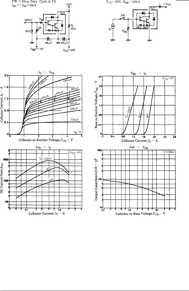
Switching Time Test Circuit Es/b Test Circuit
No.2220–2/4
 Loading...