

Sanwa Electronic Instrument Co 90490 User Manual
T R
MT-4S 2.4GHZ FH4T RADIO SYSTEM USER'S GUIDE
THROTTlE TRIGGER AnD STEERInG wHEEl SpRInG TEnSIOn ADjUSTMEnT
GEnERAl
The spring tension of the throttle trigger and steering wheel can be adjusted to best suit the user. Some users may prefer the
throttle trigger and/or steering wheel to feel 'firmer' and some users may prefer them to feel 'softer'. It all depends on your
personal preference.
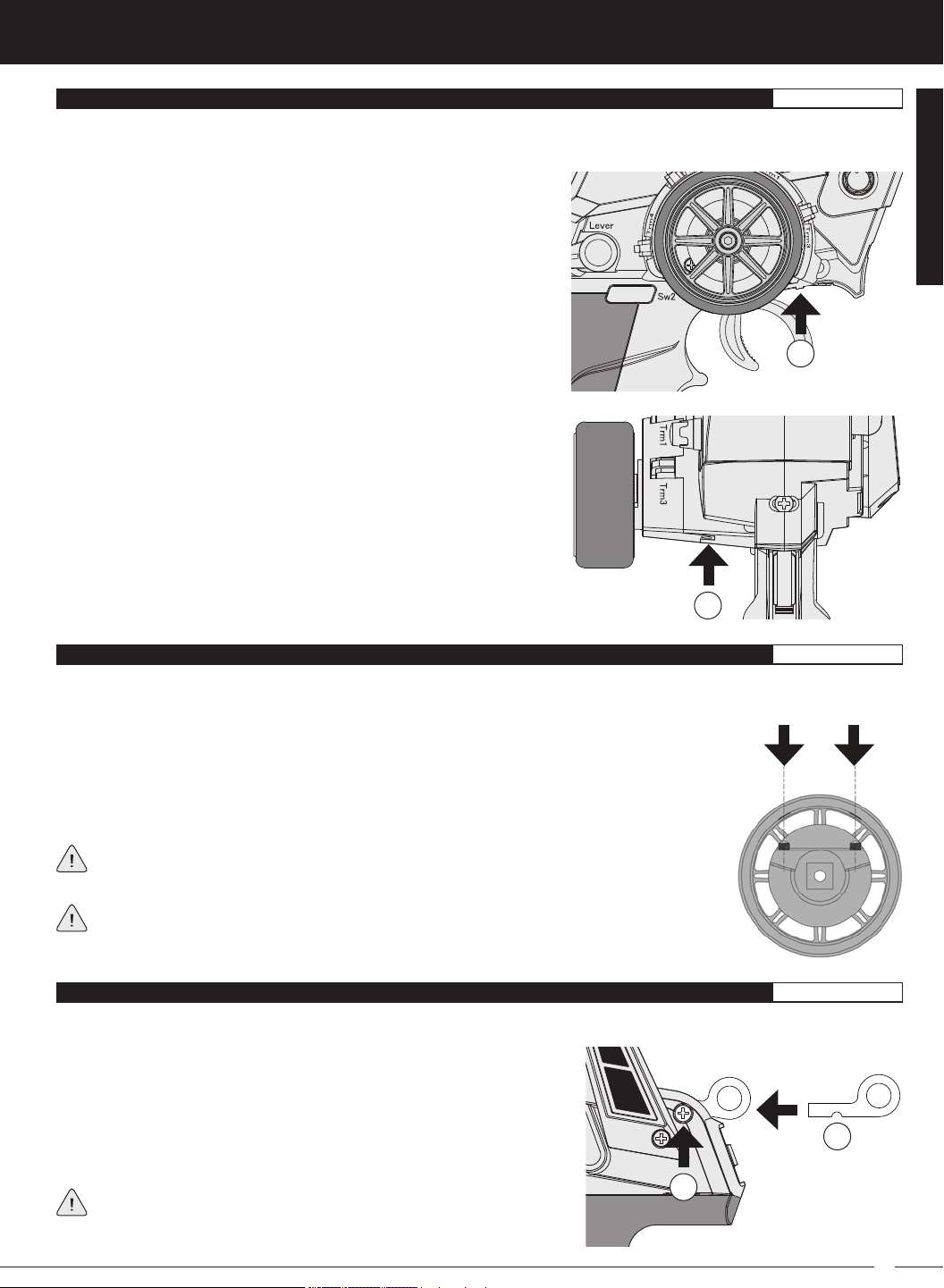
To adjust the throttle trigger spring tension, follow the step below:
1) To increase the spring tension of the throttle trigger (firmer), use a
1.5mm hex wrench to turn the Throttle Trigger Tension Adjustment
Screw (A) clockwise. To decrease the spring tension of the throttle
trigger (looser), turn the Throttle Trigger Tension Adjustment Screw
counter-clockwise.
A
To adjust the steering wheel spring tension, follow the step below:
1) To increase the spring tension of the steering wheel (firmer), use a
1.5mm hex wrench to turn the Steering Wheel Tension Adjustment
Screw (A) clockwise. To decrease the spring tension of the steering
wheel (looser), turn the Steering Wheel Tension Adjustment Screw
counter-clockwise.
A
GENERAL
STEERInG wHEEl TRAvEl ADjUSTMEnT
GEnERAl
The maximum right and left travel of the steering wheel can be adjusted to best suit the feel of the steering wheel and your driving
style. Some drivers prefer to limit the travel of the steering wheel as it makes them feel more 'connected' to their model.
To adjust the maximum travel of the steering wheel, follow the steps below:
1) Remove the foam steering wheel grip from the steering wheel by firmly pulling it straight off.
2) To limit the maximum travel of the steering wheel, use a 1.5mm hex wrench to turn both grub
screws (A) clockwise equally the desired amount. To maximize the travel of the steering wheel,
turn both grub screws counter-clockwise equally the desired amount.
After making steering wheel travel adjustments, you must use the Variable Rate Adjustment
function to ensure your steering servo travel limits are equal. For more information, see the
Variable Rate Adjustment section on page XX.
Limiting the maximum travel of the steering wheel will increase the sensitivity of the steering.
We recommend setting negative Exponential to soften the control feel around Neutral. For
more information, see the Exponential and ARC Adjustment section on pages XX through XX.
wRIST STRAp AncHOR
GEnERAl
A wrist strap anchor is included that can be installed onto the transmitter to facilitate the use of a wrist strap (not included).
To install the wrist strap anchor, follow the steps below:
1) Remove the self-tapping screw (A) from the transmitter, using a # 1 philips
head screwdriver.
2) Slide the wrist strap anchor into the mounting slot in the back of the
B
transmitter, then reinstall and tighten the self-tapping screw.
When installing the wrist strap anchor, note its orientation. The U-Shaped
A
groove in the base of the wrist strap anchor should be pointing down.
13
MT-4S 2.4GHZ FH4T RADIO SYSTEM USER'S GUIDE
TOp ScREEn AnD TElEMETRY ScREEn OvERvIEw
Use the information in this section to familiarize yourself with the layout and different indicators and displays that comprise the
TOP screen and TELEMETRY screen.
The TOP screen will always be displayed when you turn the transmitter ON, regardless of which screen was last displayed.
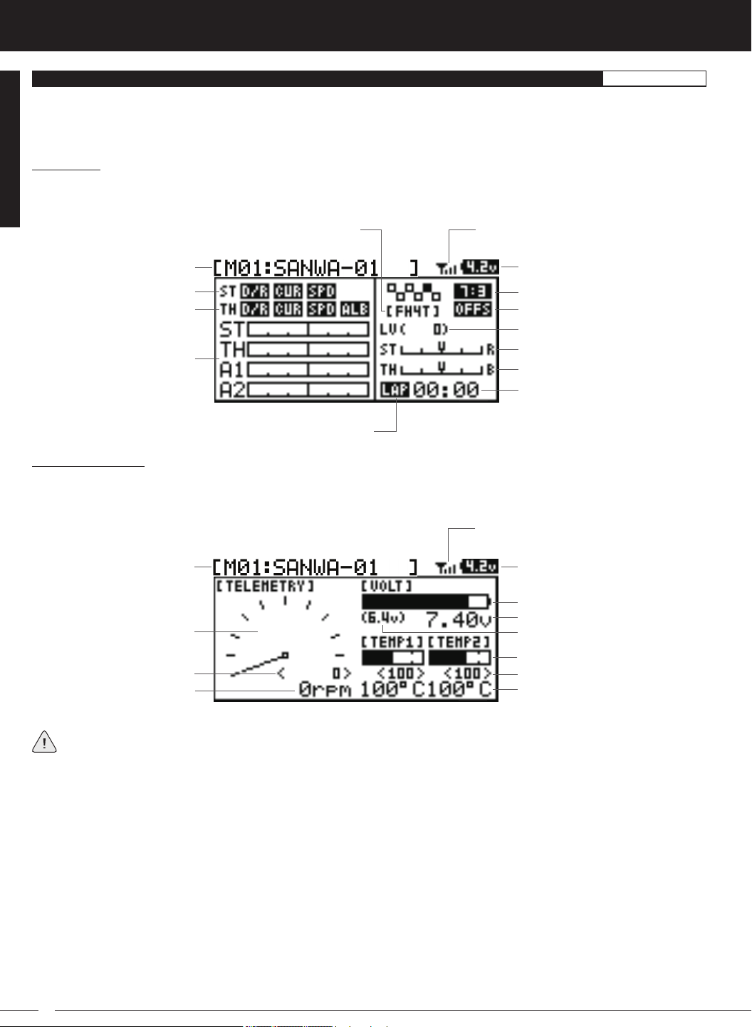
TOP Screen:
The TOP screen is displayed when you turn the transmitter ON. The TOP screen displays all pertinent information, such as the
Model Name, Modulation Type, Timer, Servo Monitor and much more.
Modulation Type Indicator
Model Number and Name
Steering Program Indicator
Throttle Program Indicator
Servo Monitor Display
Timer Type Indicator
TELEMETRY Screen:
The TELEMETRY screen displays all pertinent telemetry information, such as RPM, Temperature and Receiver Voltage. To display
the TELEMETRY screen, from the TOP screen scroll DOWN using the Push-Button Rotary Dial.
Telemetry Signal Indicator
Digital Voltage Indicator
Throttle Mode Indicator
Throttle Offset Indicator
Auxiliary Lever Position Display
Steering Trim Display
Throttle Trim Display
Timer Display
GEnERAl
Telemetry Signal Indicator
Model Number and Name Digital Voltage Indicator
Voltage Display Monitor
Receiver Voltage Display
RPM Display Monitor
High RPM Display
Digital RPM Display
Full telemetry support requires the use of an Airtronics 2.4GHz FH4T telemetry-capable surface receiver, such as the
RX-461 or RX-462 (available separately). The included RX-472 receiver can send telemetry data for the voltage of
the receiver battery pack only, unless used with the Airtronics Super Vortex ZERO ESC (available separately), plugged into the
BATT/SSL slot of the included RX-472 receiver.
Auxiliary Lever Position Display: Displays the current position of the Auxiliary Lever.
Digital RPM Display: Displays the current RPM from the RPM Sensor in digital format.
Digital Temperature Display: Displays the current temperature from the TEMP1 and TEMP2 Temperature Sensors in digital
format.
Digital Voltage Indicator: Indicates the current Voltage of the transmitter batteries.
High RPM Display: Displays the last highest RPM value. This value can be Reset. For more information, see the Telemetry Clear
Function section on page XX.
High Temperature Display: Displays the last highest Temperature value. These values can be Reset. For more information, see
the Telemetry Clear Function section on page XX.
Modulation Type Indicator: Indicates the current Modulation Type that the transmitter is set to.
Model Number and Name: Displays the Model Number and Model Name of the currently selected model.
14
Voltage Alert Indicator
Temperature Display Monitor
High Temperature Display
Digital Temperature Display
T R
MT-4S 2.4GHZ FH4T RADIO SYSTEM USER'S GUIDE
TOp ScREEn AnD TElEMETRY ScREEn OvERvIEw, cOnTInUED....
GEnERAl
Receiver Voltage Display: Displays the current voltage of the receiver battery.
RPM Display Monitor: Displays the current RPM from the RPM Sensor in graphical format.
Servo Monitor Display: Displays the output levels of the four different channels in bar graph form, allowing you to monitor servo
operation in a virtual manner.
Steering Program Indicator: Indicates up to four different programming options that are currently programmed to the Steering
channel. The Steering Program Indicator will only be displayed if a Steering channel Programming Value is programmed.
Steering Trim Display: Displays the current position of the Steering Trim Switch.
Telemetry Signal Indicator: Indicates the current signal strength of the Telemetry connection between the transmitter and
receiver. The Telemetry Signal Indicator will only be displayed when the receiver is turned ON and there is a Telemetry connection Active.
Temperature Display Monitor: Displays the current TEMP1 and TEMP2 temperatures in bar graph format.
Throttle Mode Indicator: Indicates the current Throttle Mode type.
Throttle Offset Indicator: Indicates that the Throttle Offset function is programmed. The Throttle Offset Indicator will only be
displayed if a Throttle Offset percentage value is programmed.
Throttle Program Indicator: Indicates up to four different programming options that are currently programmed to the Throttle
channel. The Throttle Program Indicator will only be displayed if a Throttle channel Programming Value is programmed.
Throttle Trim Display: Displays the current position of the Throttle Trim Switch.
Timer Display: Displays the time of the currently selected Timer.
Timer Type Indicator: Indicates the current Timer Type selected, either LAP or INT (Interval).
Voltage Alert Indicator: Indicates the currently programmed Voltage value that the receiver Voltage Alert alarm will sound at.
Voltage Display Monitor: Displays the current receiver battery voltage in bar graph format.
GENERAL
pROGRAMMInG kEYS OvERvIEw AnD FUncTIOnS
GEnERAl
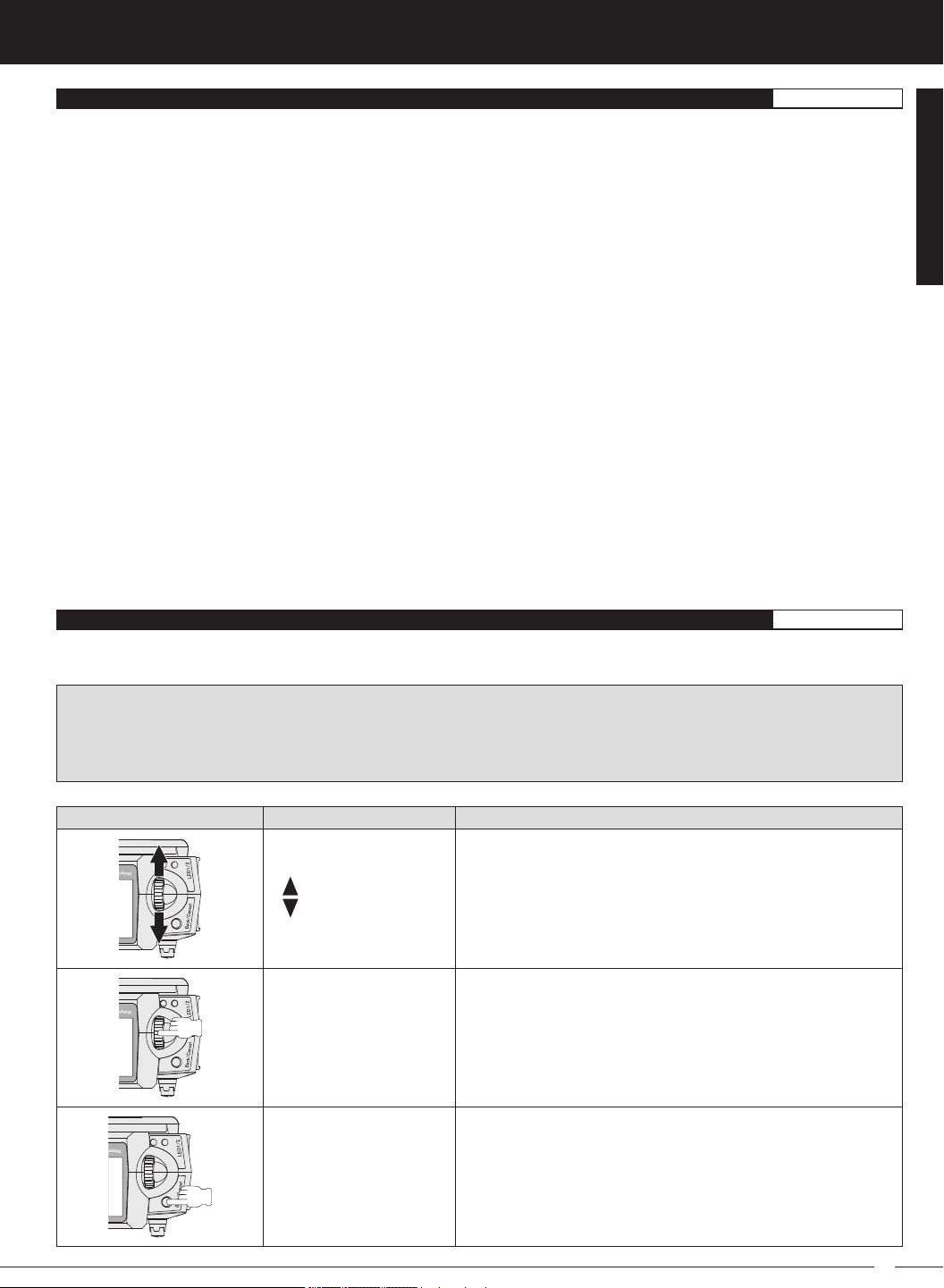
The MT-4S transmitter features a Push-Button Rotary Dial and a BACK/CANCEL key that are used to facilitate transmitter
programming. This section summarizes the functions of the Push-Button Rotary Dial and the BACK/CANCEL key.
PRO TIP: While navigating Programming Menus and changing Programming Values, keep the following in mind: to choose
an option to program, scroll UP or DOWN to highlight the desired option. Press the ENTER key and the highlighted option will
flash, indicating the Programming Value can be changed. Once you've changed the Programming Value, press the ENTER
key again or press the BACK/CANCEL key and the highlighted option will stop flashing, indicating you can scroll UP or DOWN
to highlight another programming option.
PROGRAMMING KEY NAME FUNCTION
Push-Button
Rotary Dial
(Scroll UP/DOWN)
Push-Button Rotary Dial
(Push ENTER)
Scrolls between TOP and TELEMETRY screens. Scrolls the
Programming Cursor RIGHT or UP and LEFT or DOWN. Increases
or Decreases Programming Values.
Opens the selected menu or programming option. Press and
HOLD to reset the Selected programming option to its default
value.
BACK/CANCEL Key
Returns to the previous menu. Press and HOLD to return to the
TOP screen.
15
MT-4S 2.4GHZ FH4T RADIO SYSTEM USER'S GUIDE
bInDInG THE TRAnSMITTER AnD REcEIvER
The Binding function allows you to 'Bind' the transmitter and receiver pair. When new, it is necessary to pair the transmitter and
receiver to prevent interference from transmitters operated by other users. This operation is referred to as 'Binding'. Once the
Binding process is complete, the setting is remembered even when the transmitter and receiver are turned OFF. Therefore, this
procedure usually only needs to be done once.
Under some circumstances, the receiver may not operate after turning the transmitter and receiver ON. If this occurs,
perform the Binding process again.
IMPORTANT: This section details Binding the RX-472 4-Channel 2.4GHz FH4T Super Response receiver with the Servo
Operating Mode set to Normal mode. If you are Binding an FH2 or FH3 receiver, or if you prefer to change the Servo Operating
Mode, see the
Before beginning the Binding process, connect your servos and receiver battery pack to the receiver. For more information,
see the
Transmitter and Receiver Binding:
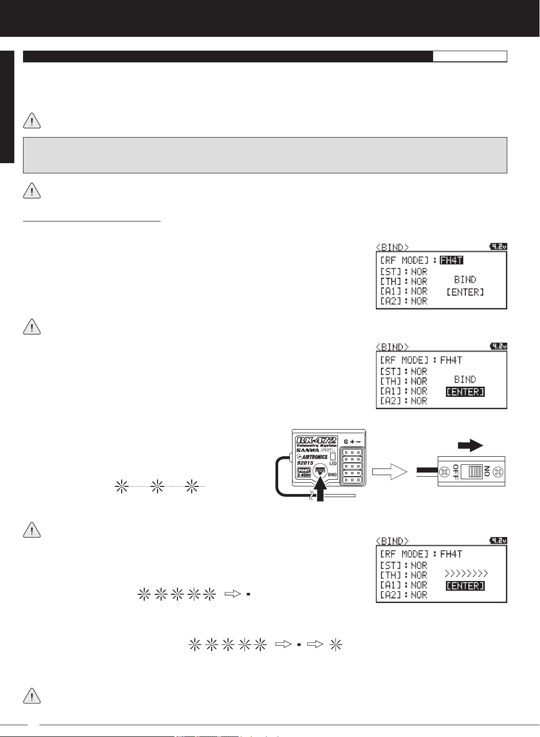
1) Turn the transmitter ON. The TOP screen will be displayed. Press the ENTER key (Push-Button Rotary Dial) to open the
Programming Menu list, then scroll UP or DOWN to highlight the SYSTEM menu.
2) Press the ENTER key to open the SYSTEM menu, then scroll DOWN to highlight the
BIND menu. Press the ENTER key to open the BIND menu.
Verify that the Modulation is set to [RF MODE]: FH4T is displayed an that the Servo Operating Mode for each channel is set
to NOR. If it isn't, change the Modulation Type to FH4T. If you need to change any of these settings, see the
section on pages XX through XX.
BIND Menu
section on pages XX through XX.
Receiver Connections and Mounting
section on page XX. The transmitter and the receiver should be turned OFF.
GEnERAl
BIND Menu
3) Scroll UP or DOWN to highlight the [ENTER] command. Do not press the ENTER key yet.
4) While holding down the Bind Button on the receiver,
turn the receiver ON. The Bind LED on the receiver will
flash slowly. After approximately 2 seconds, release the
Bind Button. The Bind LED on the receiver will continue to
flash slowly.
You must complete step 5 below within 10 seconds or the Bind LED will go out, indicating the receiver has timed out. If
this occurs, turn the receiver OFF, then repeat step 4.
5) Press the ENTER key. The [ENTER] command will begin to flash and the Bind LED on
the receiver will flash rapidly, then go out.
6) After the Bind LED on the receiver goes out, press the ENTER key a second time. The Bind LED on the receiver will illuminate
solid blue and LED 2 on the transmitter will go out, indicating that the Binding procedure is complete and a Telemetry
connection has been made.
7) Move the steering wheel and throttle trigger to verify that the servos are operating normally, then press and HOLD the
Back/Cancel key to return to the TOP screen.
When the Binding procedure is successful, the Bind LED on the receiver and LED 1 on the transmitter will illuminate solid
blue. If the Bind LED on the receiver is flashing rapidly or is not illuminated at all, the transmitter and receiver are not
paired. In this case, turn both the transmitter and receiver OFF, then repeat the Binding procedure again.
16

T R
MT-4S 2.4GHZ FH4T RADIO SYSTEM USER'S GUIDE
overview
To access the various Programming Menus, turn the transmitter ON, then press the ENTER key (Push-Button Rotary Dial).
A list of Programming Menus will be displayed along the right side of the screen and the last Programming Menu when
the transmitter was turned OFF will be highlighted. The currently highlighted Programming Menu will be displayed in the
background.
The following Programming Menus are available by scrolling UP or DOWN using the Push-Button Rotary Dial:
M E N U MENU NAME MENU DESCRIPTION
PAGE #
01.CH-SET
02.D/R
03.EPA
04.CURVE
05.SPEED
06.ALB
07.OFFSET
08.AUX1
09.AUX2
MENUS
10.TRIM
11.REV
PROGRAMMING
12.TIMER
13.LAP
14.F/S
15.LOGGER
16.SYSTEM
Channel Set
Dual Rate
End Point Adjustment
Curve
Servo Speed
Anti-Lock Braking
Throttle Offset
Auxiliary 1
Auxiliary 2
Servo Trim
Servo Reversing
Lap and Interval Timers
Lap Times
Fail Safe
Telemetry Logging
System Menu
Change Common Programming Options in One Convenient Location
Adjust Channel Dual Rates
Adjust Channel End Points
Adjust Channel Exponential or Adjustable Rate Control (ARC)
Slow Down Servo Speed in the Forward and Return to Neutral Direc-
tions
Program the Anti-Lock Braking Function
Program the Throttle Offset Position
Choose and Adjust Auxiliary 1 Channel 3 Functions and Programming
Choose and Adjust Auxiliary 2 Channel 4 Functions and Programming
Adjust Servo Trim and Servo Sub-Trim
Change the Direction that the Servos Travel
Program the Lap Timer and the Interval Timer
Displays Current, Past and Best Lap Times
Program Fail Safe Settings
View Logs of Temperature, Voltage and RPM Telemetry Data
Access the System Menu
PG. 19
PG. 20
PG. 22
PG. 23
PG. 25
PG. 27
PG. 28
PG. 29
PG. 36
PG. 42
PG. 44
PG. 44
PG. 47
PG. 48
PG. 49
PG. 51
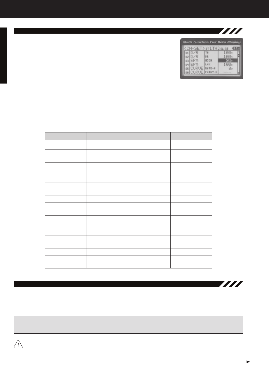
01.CH-Set (CHannel Set)
The Channel Set function allows you to make programming changes to each of the four channels without the need to
enter each Programming Menu separately. Essentially, the Channel Set function encompasses the most common programming options in one convenient location. For example, you can make all of your desired programming changes,
such as End Point Adjustment, Exponential, Servo Speed, Fail Safe settings, etc., for each channel, all from within the
same menu.
This section details how to use the Channel Set function. For information about programming each of the Programming Menus within the CH-SET menu, refer to the specific Programming Menu sections on the pages shown in
the table above.
1) From the TOP screen, press the ENTER key to open the Programming Menu list.
2) Scroll UP or DOWN to highlight the CH-SET menu, then press the ENTER key. The
CH-SET menu will be displayed and the cursor will default to [ST].
3) Scroll DOWN to move the cursor to the channel you would like to make Programming Value changes to. Choose from <CH-SET> [ST] (Steering), <CH-SET> [TH]
(Throttle), <CH-SET> [A1] (Auxiliary 1) or <CH-SET> [A2] (Auxiliary 2).
17
MT-4S 2.4GHZ FH4T RADIO SYSTEM USER'S GUIDE
[[ProGraMMinG MenuS
01.CH-Set (CHannel Set), Continued....
4) Press the ENTER key to highlight the Programming Value in the upper right corner.
5) Scroll UP or DOWN to highlight the Programming Value you would like to change,
then press the ENTER key to select it. The highlighted Programming Value will
6) After changing the desired Programming Value, press the ENTER key or the Back/Cancel key and the highlighted
option will stop flashing, indicating you can scroll UP or DOWN to highlight another programming option. To change
to another channel, press the Back/Cancel key, then scroll UP or DOWN to select the desired channel. Repeat steps
4 and 5 above to change the desired Programming Values for that channel.
01.D/R - RATE
02.EPA - L/R
03.EPA - LEFT
04.EPA - RIGHT
05.CURVE - RATE
06.CURVE - POINT
07.SPEED - FORWARD
08.SPEED - RETURN
0 9 . T R I M
1 0 . S U B - T
11.REV - NOR/REV
1 2 . F / S
01.D/R - TH
02.D/R - BR
03.EPA - HIGH
04.EPA - LOW
05.CURVE - RATE-H
06.CURVE - POINT-H
07.CURVE - RATE-B
08.CURVE - RATE-H
09.SPEED - FORWARD
10.SPEED - RETURN
11.ALB - POINT
12.ALB - STROKE
13.ALB - LAG
14.ALB - RELEASE
15.ALB - HOLD
1 6 . T R I M
1 7 . S U B - T
18.REV - NOR/REV
01.EPA - HIGH
02.EPA - LOW
03.CURVE - RATE
04.CURVE - POINT
0 5 . C U R V E
0 6 . C U R V E
07.SPEED - FORWARD
08.SPEED - RETURN
0 9 . T R I M
1 0 . S U B - T
11.REV - NOR/REV
01.EPA - HIGH
02.EPA - LOW
03.CURVE - RATE
04.CURVE - POINT
0 5 . C U R V E
0 6 . C U R V E
07.SPEED - FORWARD
08.SPEED - RETURN
0 9 . T R I M
1 0 . S U B - T
11.REV - NOR/REV
02.d/r (dual rate)
The Dual Rate function allows you to change the control authority of the Steering, Throttle High Side and Throttle Brake
Side by changing the amount of servo travel relative to control input. For example, by increasing the Steering Dual Rate,
you can make the steering servo travel more which might prevent your model from pushing during turns. If your model
IMPORTANT: Prior to programming the Dual Rate function, you should adjust the maximum Left and Right (or High
and Low) End Points, using the End Point Adjustment function. For more information, see the End Point Adjustment
section on pages 22 and 23.
Dual Rate is a percentage of End Point Adjustment. For example, if you set the Steering Dual Rate percentage
value to 100%, the steering will travel the same amount as defined by your End Point Adjustment programming. If you
18
T R
MT-4S 2.4GHZ FH4T RADIO SYSTEM USER'S GUIDE
[[ProGraMMinG MenuS
02.d/r (dual rate), Continued....
PRO TIP: Use the Servo Monitor at the bottom of the Dual Rate menu to see your programming changes in virtual real
Adjusting the Steering Dual Rate Percentage Value
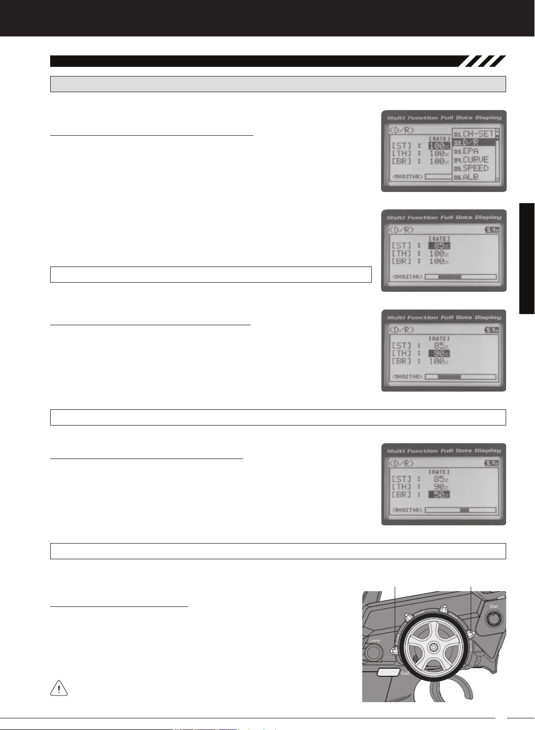
1) From the TOP screen, press the ENTER key to open the Programming Menu list.
2) Scroll UP or DOWN to highlight the D/R menu, then press the ENTER key. The D/R
3) Press the ENTER key, then scroll UP or DOWN to increase or decrease the Steering Dual Rate percentage value. When the Steering Dual Rate percentage value is
decreased, steering servo travel is decreased. When the Steering Dual Rate per-
D/R ST RATE setting range is 0% to 100%. The default setting is 100%.
Adjusting the Throttle Dual Rate Percentage Value
1) From within the D/R menu, scroll UP or DOWN to highlight [TH] : RATE 100%.
2) Press the ENTER key, then scroll UP or DOWN to increase or decrease the Throttle
Dual Rate percentage value. When the Throttle Dual Rate percentage value is decreased, Throttle High side servo travel is decreased. When the Throttle Dual Rate
D/R TH RATE setting range is 0% to 100%. The default setting is 100%.
Adjusting the Brake Dual Rate Percentage Value
1) From within the D/R menu, scroll UP or DOWN to highlight [BR] : RATE 100%.
2) Press the ENTER key, then scroll UP or DOWN to increase or decrease the Brake
Dual Rate percentage value. When the Brake Dual Rate percentage value is decreased, Throttle Brake side servo travel is decreased. When the Brake Dual Rate
D/R BR RATE setting range is 0% to 100%. The default setting is 100%.
Controlling the Dual Rate Function
1) By assigning the Steering, Throttle and Brake Dual Rate programming functions to one or more of the Trim Switches, Auxiliary Lever or Dial Knob, these
functions can be adjusted while driving without accessing the Programming Menu. In addition, these functions can be toggled OFF and ON by
assigning them to one or more Push-Button Switches. For more information,
In the default configuration, the Steering and Throttle Dual Rate program-
19
MT-4S 2.4GHZ FH4T RADIO SYSTEM USER'S GUIDE
[[ProGraMMinG MenuS
03.ePa (end Point adjuStMent)
The End Point Adjustment function allows you to adjust servo travel in each direction. This makes it possible to balance
servo travel in both directions and set the maximum desired amount of servo travel. For example, on a gas-powered
model, if you pull the throttle trigger and the carburetor does not open completely, you can increase the Throttle High End
Point Adjustment so that the carburetor opens completely. Another example is with steering. If your model turns sharper
to the right than to the left, you can increase the Steering Left End Point Adjustment to balance the steering. The End
Point Adjustment function can be adjusted for the Steering channel (Right and Left), the Throttle channel (Throttle High
WARNING End Point Adjustment percentage values should not be increased to the point where your linkages and
servos bind when moved all the way to the right or left. Binding will cause the servos to 'buzz', resulting in a quicker
loss of battery power and eventual damage to the servos.
PRO TIP: Use the Servo Monitor at the bottom of the End Point Adjustment menu to see your programming changes
in virtual real time.
Before making End Point Adjustments, the servo horn needs to be centered. Install the servo horn onto the servo,
making sure it's as close to being centered as possible, then use the Servo Sub-Trim function to center the servo
Adjusting the Steering End Point Adjustment Percentage Values
Your model’s turning radius can differ from left to right because of variations in linkage, suspension balance, tire diameter,
or weight distribution. In such cases, Left Steering servo travel and Right Steering servo travel are adjustable using the
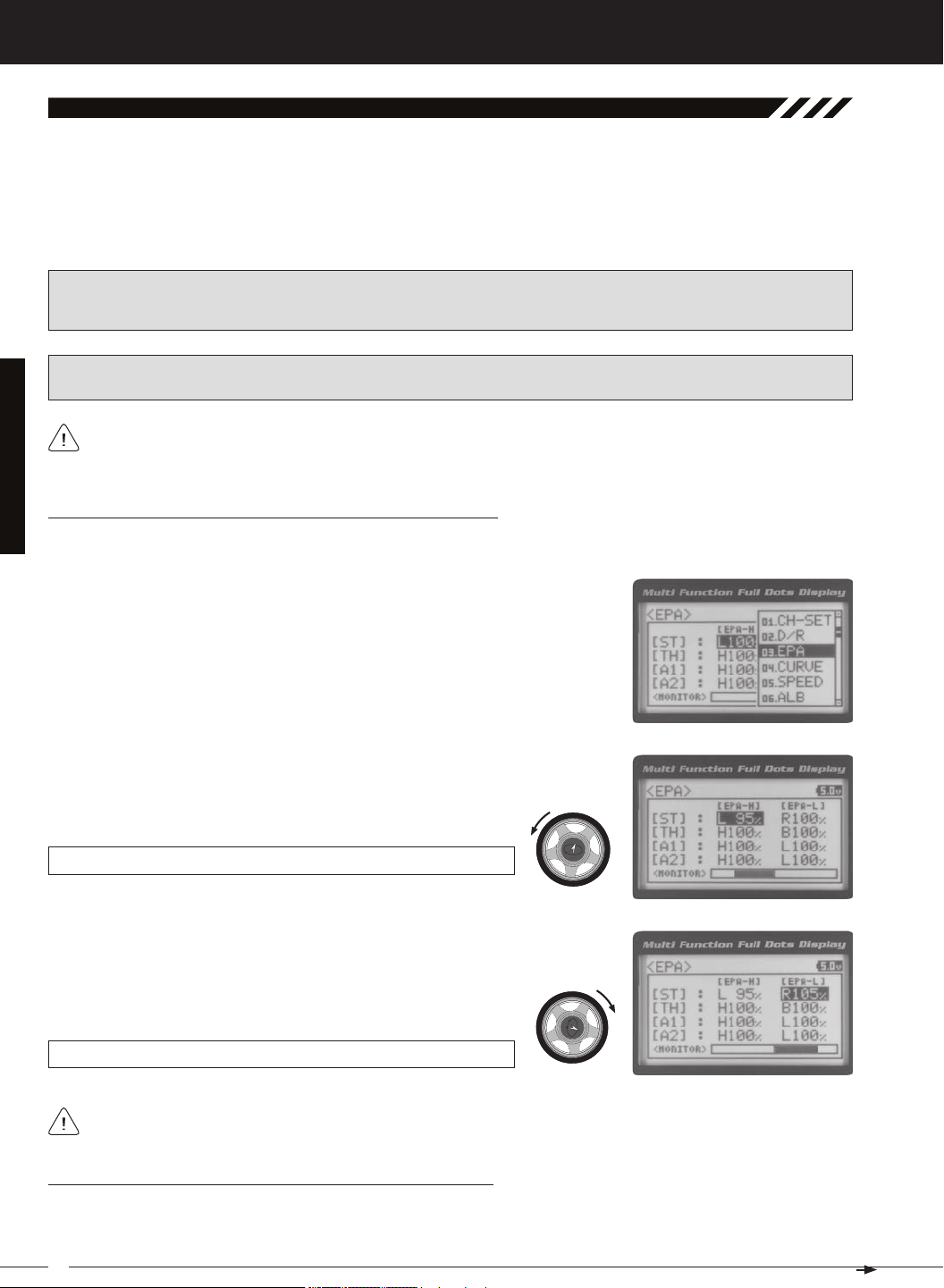
1) From the TOP screen, press the ENTER key to open the Programming Menu list.
2) Scroll UP or DOWN to highlight the EPA menu, then press the ENTER key. The
3) Press the ENTER key, then scroll UP or DOWN to increase or decrease the Steering
Left End Point Adjustment percentage value. Increasing the percentage value will
increase steering servo travel in that direction and decreasing the percentage value
EPA ST L setting range is 0% to 150%. The default setting is 100%.
4) From within the EPA menu, scroll DOWN to highlight [ST] : EPA R100%. Press
the ENTER key, then scroll UP or DOWN to increase or decrease the Steering
Right End Point Adjustment percentage value. Increasing the percentage value
will increase steering servo travel in that direction and decreasing
EPA ST R setting range is 0% to 150%. The default setting is 100%.
Steering EPA L/R can be adjusted from within the Channel Set menu. This option changes both Left and Right
Adjusting the Throttle End Point Adjustment Percentage Values
Your model's carburetor may not open completely, or it may open too much and cause the throttle servo to bind. If you're
using an Electronic Speed Control, the Electronic Speed Control may not command full power, or the brake may not
20
T R
MT-4S 2.4GHZ FH4T RADIO SYSTEM USER'S GUIDE
[[ProGraMMinG MenuS
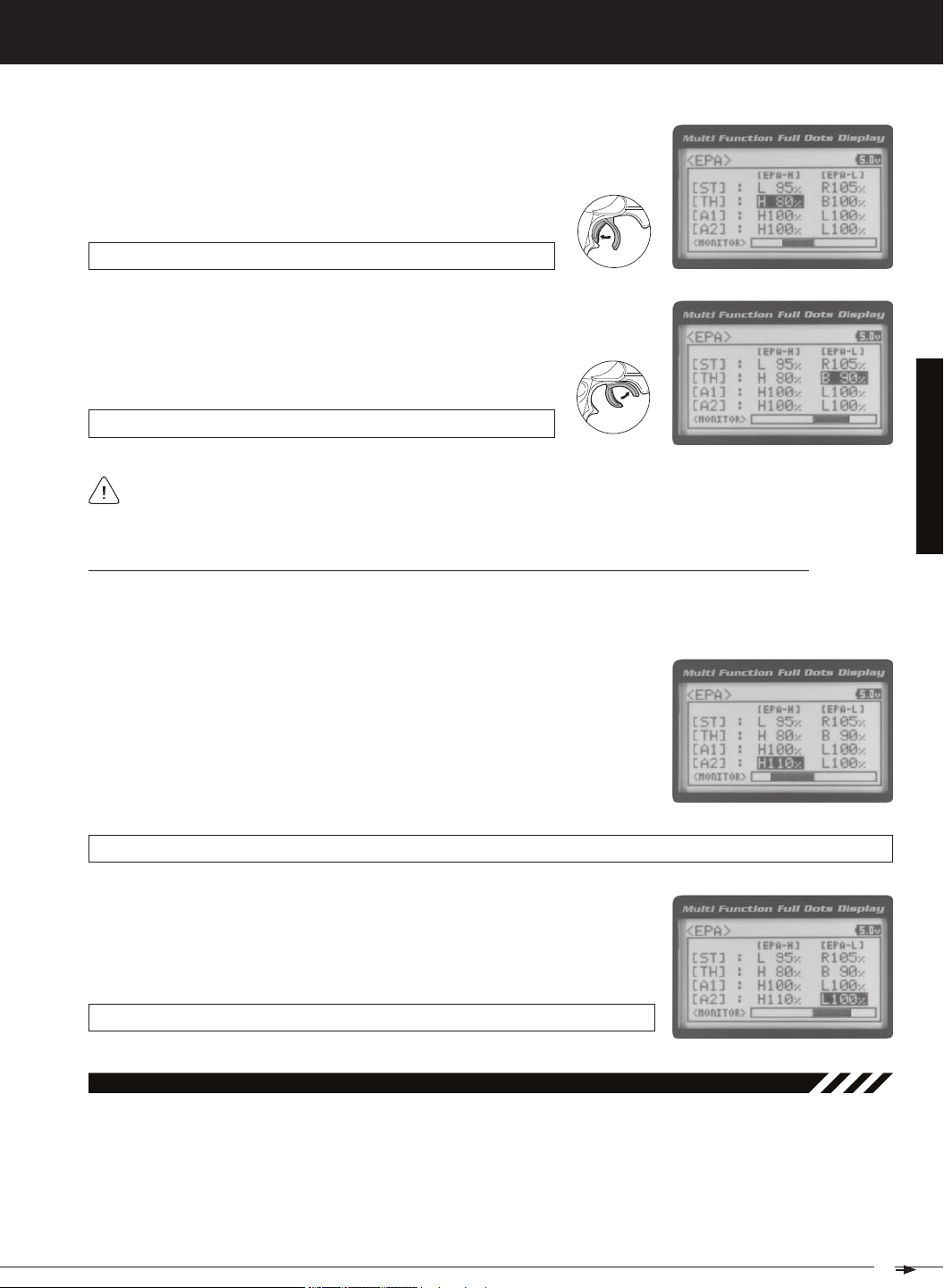
1) From within the EPA menu, scroll UP or DOWN to highlight [TH] : EPA H 100%.
2) Press the ENTER key, then scroll UP or DOWN to increase or decrease the Throttle
High End Point Adjustment percentage value. Increasing the percentage value will
increase Throttle High servo travel in that direction and decreasing
EPA TH H setting range is 0% to 150%. The default setting is 100%.
3) From within the EPA menu, scroll DOWN to [TH] : EPA B100%. Press the ENTER key, then scroll UP or DOWN to increase or decrease the Throttle Brake
End Point Adjustment percentage value. Increasing the percentage value will increase Throttle Brake servo travel in that direction and decreasing
EPA TH B setting range is 0% to 150%. The default setting is 100%.
If you're using an Electronic Speed Control, the Throttle High and the Throttle Brake End Point Adjustment percentage values are both generally set to 100%, although the Throttle High direction may need to be increased to
Adjusting the Auxiliary 1 Channel 3 and Auxiliary 2 Channel 4 End Point Adjustment Percentage Values
Auxiliary 1 Channel 3 and Auxiliary 2 Channel 4 can be used for a number of different uses. One of the more common
uses would be for the reverse function in a glow-powered monster truck. Often, the transmission only requires a small
amount of throw, but the servo binds because of too much servo travel. In such a case, Auxiliary High servo travel and
1) From within the EPA menu, scroll UP or DOWN to highlight [A1] : EPA H 100%
or [A2] : EPA H 100%.
2) Press the ENTER key, then scroll UP or DOWN to increase or decrease the Auxiliary High End Point Adjustment percentage value. Increasing the percentage
value will increase auxiliary servo travel in that direction and decreasing the
EPA A1 H and EPA A2 H setting range is 0% to 150%. The default setting is 100%.
3) From within the EPA menu, scroll UP or DOWN to highlight [A1] : EPA L100% or
[A2] : EPA L100%. Press the ENTER key, then scroll UP or DOWN to increase or
decrease the Auxiliary Low End Point Adjustment percentage value. Increasing the percentage value will increase auxiliary servo travel in that direction and
EPA A1 L and EPA A2 L setting range is 0% to 150%. The default setting is 100%.
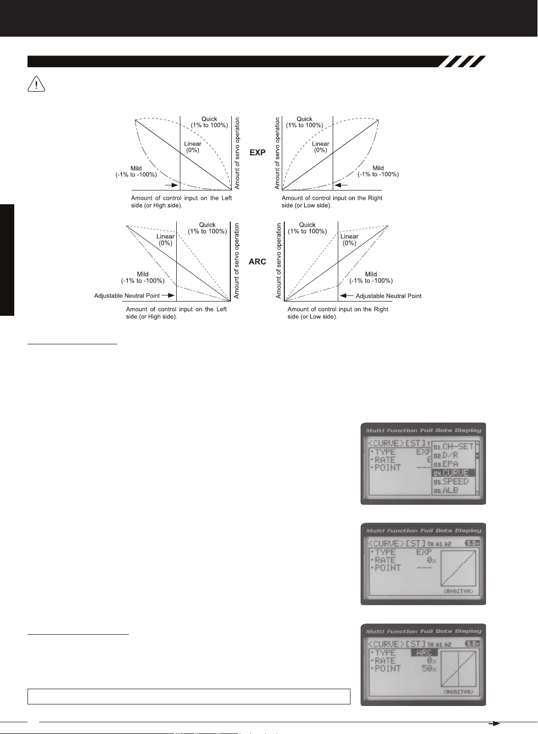
04.Curve (eXPonential and arC adjuStMent)
The Exponential and Adjustable Rate Control (ARC) functions allow you to vary the amount of servo travel in relation
to the movement of the steering wheel, throttle trigger and auxiliary lever near the Neutral positions to change the way
those functions react to control movement. Decreasing the Exponential or Adjustable Rate Control percentage values
will soften the control feel around Neutral and increasing the Exponential or Adjustable Rate Control percentage values
will heighten the control feel around Neutral. Using a lower negative value allows for smoother control. Using a higher
positive value may result in more 'twitchy' control response. The Exponential and Adjustable Rate Control functions can
be adjusted for the Steering channel, the Throttle channel (Throttle High and Throttle Brake), Auxiliary 1 Channel 3 and
21
MT-4S 2.4GHZ FH4T RADIO SYSTEM USER'S GUIDE
[[ProGraMMinG MenuS
04.Curve (eXPonential and arC adjuStMent, Continued....)
The Exponential and Adjustable Rate Control functions work the same, except the Exponential Rate percentage
value is programmed from a fixed Neutral Point of 50% and the Adjustable Rate Control Rate percentage value is
Choosing the Channel
Exponential or Adjustable Rate Control percentage values can be adjusted from Mild through Linear to Quick to allow
you to set the most effective control response for your model. For example, if your model over-steers, reduce the Steering
Exponential or Adjustable Rate Control percentage value, and if your model under-steers, increase the Steering Exponential or Adjustable Rate Control percentage value. As another example, reduce the Throttle Exponential or Adjustable Rate
Control percentage value on a slippery track or with a model that has a higher-torque motor or engine, and increase the
1) From the TOP screen, press the ENTER key to open the Programming Menu list.
2) Scroll UP or DOWN to highlight the CURVE menu, then press the ENTER key. The
3) Scroll DOWN to move the cursor to the channel you would like to make Programming Value changes to. Choose from <CURVE> [ST] (Steering), <CURVE> [TH]
Choosing the Curve Type
1) Press the ENTER key to highlight TYPE EXP. Press the ENTER key a second time,
then scroll UP or DOWN to choose the desired Curve Type. If you are programming
the Curve function for the Throttle channel, you have the option of adjusting the
CURVE TYPE setting range is EXP and ARC. The default setting is EXP.
22

T R
MT-4S 2.4GHZ FH4T RADIO SYSTEM USER'S GUIDE
[[ProGraMMinG MenuS
04.Curve (eXPonential and arC adjuStMent, Continued....)
Adjusting the Rate Percentage Value
1) From within the CURVE menu, scroll DOWN to highlight RATE 0%. Press the ENTER key, then scroll UP or DOWN to increase or decrease the Rate percentage
value. Using a negative Rate percentage value will soften the control feel around
CURVE RATE setting range is -100% (Mild) to 100% (Quick). The default setting is 0%
Changes to the Rate percentage value affects both the channel High side and Low side equally, except for the
Adjusting the Point Percentage Value
The Point percentage value determines the Neutral Point where the Rate percentage value begins. For example, you
1) From within the CURVE menu, scroll DOWN to highlight POINT 50%. Press the ENTER key, then scroll UP or DOWN to increase or decrease the Point percentage
value. Increasing the Point percentage value will shift the Neutral Point to one side
of center and decreasing the Point percentage value will shift the Neutral Point to
CURVE POINT setting range is 5% to 95%. The default setting is 50% (Centered).
Controlling the Curve Function
1) By assigning the Steering, Throttle High and Throttle Brake Rate and Point programming functions to one or more of
the Trim Switches, Auxiliary Lever or Dial Knob, these functions can be adjusted while driving without accessing the
Programming Menu. In addition, the Steering Curve and Throttle Curve functions can be Toggled OFF and ON by as-
05.SPeed (Servo SPeed)
The Servo Speed function allows you to slow the transit speed of the Steering, Throttle, Auxiliary 1 and Auxiliary 2 servos.
Servo transit speed can be slowed in both the Forward and the Return to Neutral directions independently. When driving your model, proper steering and throttle control are vital. For example, lowering the transit speed of the steering
servo can help to limit excessive steering, which will enable you to achieve smoother cornering. In addition, lowering the
PRO TIP: Use the Servo Monitor at the bottom of the Speed menu to see your programming changes in virtual real time.
23

MT-4S 2.4GHZ FH4T RADIO SYSTEM USER'S GUIDE
[[ProGraMMinG MenuS
05.SPeed (Servo SPeed), Continued....
Adjusting the Forward Speed Value
1) From the TOP screen, press the ENTER key to open the Programming Menu list.
2) Scroll UP or DOWN to highlight the SPEED menu, then press the ENTER key. The
3) Scroll UP or DOWN to highlight the desired channel you would like to change the
Forward Speed value for. Choose from either [ST] : F ORWARD 0 (Steering),
[TH] : FORWARD 0 (Throttle), [A1] : FORWARD 0 (Auxiliary 1) or [A2] : FORWARD 0
4) Press the ENTER key, then scroll DOWN to decrease servo Speed in the Forward
direction. Decreasing the Forward Speed value will cause the servo transit time
SPEED FORWARD setting range is -100 to 0. The default setting is 0 (Normal
IMPORTANT: Throttle Servo Speed affects only the Throttle High Side. The Throttle Brake Side is unaffected. See
Throttle diagram on previous page.
Adjusting the Return to Neutral Speed Value
1) From within the SPEED menu, scroll UP or DOWN to highlight the desired channel you would like to change the Return to Neutral Speed value for. Choose from
either [ST] : RETURN 0 (Steering), [TH] : RETURN 0 (Throttle), [A1] : RETURN 0
2) Press the ENTER key, then scroll DOWN to decrease servo Speed in the Return
to Neutral direction. Decreasing the Return to Neutral Speed value will cause the
SPEED RETURN setting range is -100 to 0. The default setting is 0 (Normal Speed).
Controlling the Servo Speed Function
1) By assigning the Steering and Throttle Forward and Return to Neutral Speed programming functions to one or more
of the Trim Switches, Auxiliary Lever or Dial Knob, these functions can be adjusted while driving without accessing the
Programming Menu. In addition, the Steering Speed and Throttle Speed functions can be Toggled OFF and ON by
24
T R
MT-4S 2.4GHZ FH4T RADIO SYSTEM USER'S GUIDE
[[ProGraMMinG MenuS
06.alb (anti-loCk brakinG)
The Anti-Lock Braking function makes it possible to achieve stable braking even on a slippery surface. With stable braking, your model is better able to trace an exact line under braking. The Anti-Lock Braking function also enables you to set
different braking characteristics depending on your particular model. Different Anti-Lock Braking function options can
PRO TIP: Use the Servo Monitor at the bottom of the ALB menu to see your programming changes in virtual real time.
The Anti-Lock Braking function operates only when the throttle trigger is moved from Neutral to the Brake side. Set
the hardest braking you can obtain from your model by carefully setting the Anti-Lock Braking function at the point
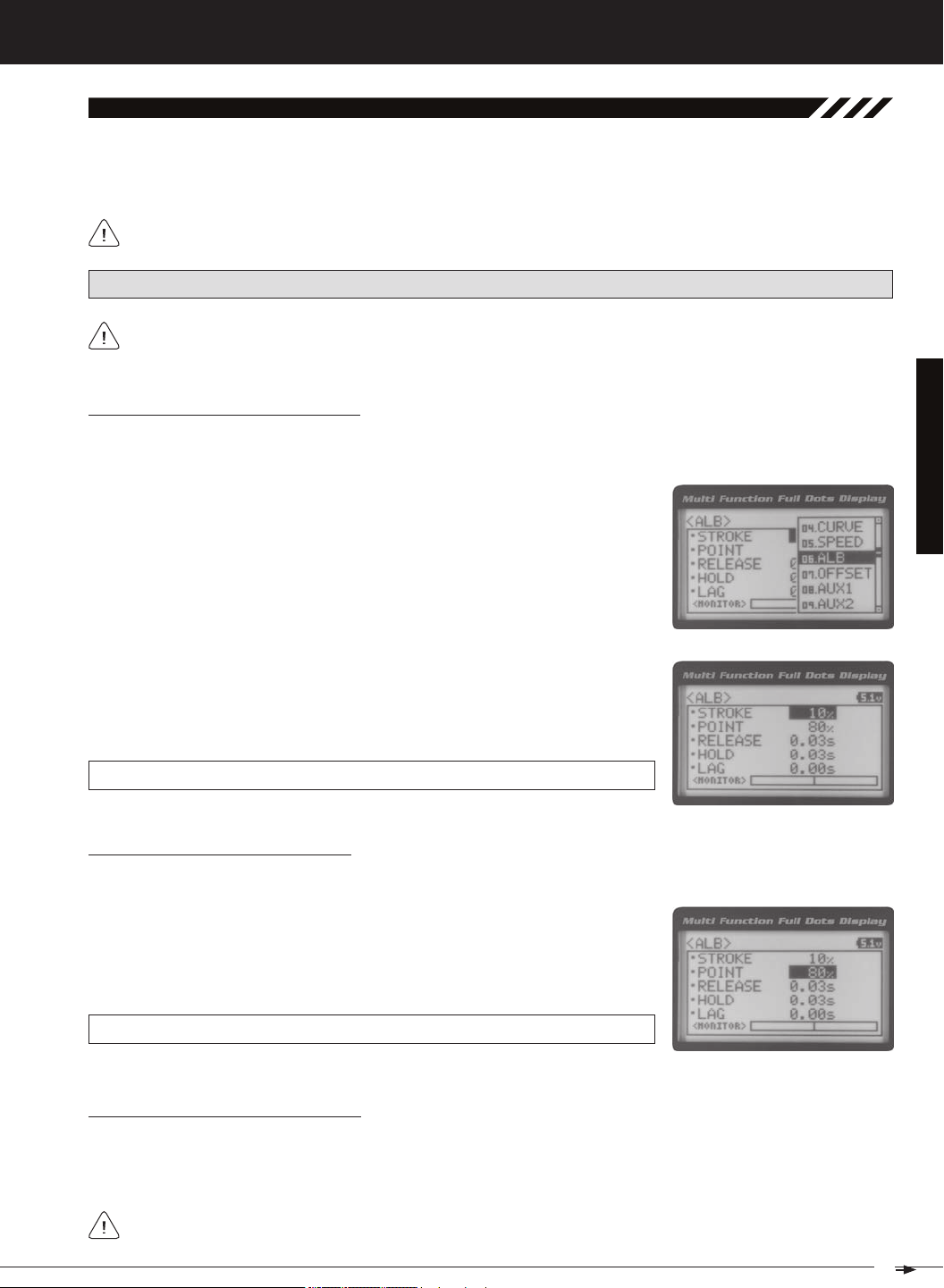
Adjusting the Stroke Percentage Value
The Stroke percentage value determines the amount of Brake that's applied automatically when the Anti-Lock Braking
function Activates. When set to OFF, the Anti-Lock Braking function will not work. A percentage value of 1% or greater
1) From the TOP screen, press the ENTER key to open the Programming Menu list.
2) Scroll UP or DOWN to highlight the ALB menu, then press the ENTER key. The
3) Press the ENTER key, then scroll UP or DOWN to increase or decrease the Stroke
percentage value. Increasing the Stroke percentage value will increase throttle
servo travel in the Brake direction and decreasing the Stroke percentage value
ALB STROKE setting range is OFF to 100%. The default setting is OFF.
Adjusting the Point Percentage Value
1) From within the ALB menu, scroll DOWN to highlight POINT 80%. Press the ENTER key, then scroll UP or DOWN to increase or decrease the Point percentage
value. Increasing the Point percentage value will cause the Anti-Lock Braking
function to Activate later and decreasing the Point percentage value will cause
ALB POINT setting range is 5% to 100%. The default setting is 80%.
Adjusting the Release and Hold Values
The Release and Hold values determine the speed at which the brake pulsates. By adjusting the Release and Hold values, you can make the brake pulsate faster or slower. The Release value determines how quickly the Brake moves from
Neutral to the percentage value determined by the Stroke setting and the Hold value determines how quickly the Brake
We recommend using equal Release and Hold values, although different values can be used to fine-tune how
25
MT-4S 2.4GHZ FH4T RADIO SYSTEM USER'S GUIDE
[[ProGraMMinG MenuS
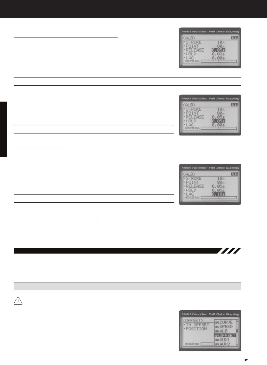
Adjusting the Release and Hold Values, Continued....
1) From within the ALB menu, scroll DOWN to highlight RELEASE 0.03s. Press the
ENTER key, then scroll UP or DOWN to increase or decrease the Release value.
Increasing the Release value will cause the Brake to move from Neutral to the
Stroke setting slower and decreasing the Release value will cause the Brake to
ALB RELEASE setting range is 0.01s to 1.00s. The default setting is 0.03s.
2) From within the ALB menu, scroll DOWN to highlight HOLD 0.03s. Press the ENTER
key, then scroll UP or DOWN to increase or decrease the Hold value. Increasing
the Hold value will cause the Brake to move from the Stroke setting to the Neutral
position slower and decreasing the Hold value will cause the Brake to move from
ALB HOLD setting range is 0.01s to 1.00s. The default setting is 0.03s.
Adjusting the Lag Value
1) From within the ALB menu, scroll DOWN to highlight LAG 0.00s. Press the ENTER
key, then scroll UP and DOWN to increase or decrease the Lag value. Increasing
the Lag value increases the delay time to Activate the Anti-Lock Braking function after reaching the Point setting and decreasing the Lag value decreases
ALB LAG setting range is 0.00s to 1.00s. The default setting is 0.00s.
Controlling the Anti-Lock Braking Function
1) By assigning the Anti-Lock Braking Point, Stroke, Lag, Hold and Release programming functions to one or more of
the Trim Switches, Auxiliary Lever or Dial Knob, these functions can be adjusted while driving without accessing the
Programming Menu. In addition, the Anti-Lock Braking function can be Toggled OFF and ON by assigning it to one of
07.offSet (tHrottle offSet)
The Throttle Offset function allows you to shift the Neutral position of the throttle servo, either toward the High Side or the
Brake Side. When used in conjunction with a Push-Button Switch, this function can be used several different ways. For
example, if you're driving a glow- or gas-powered model, you can program the Throttle Offset function to shut down your
PRO TIP: Use the Servo Monitor at the bottom of the OFFSET menu to see your programming changes in virtual real
Turning the Throttle Offset Function ON or OFF
1) From the TOP screen, press the ENTER key to open the Programming Menu list.
2) Scroll UP or DOWN to highlight the OFFSET menu, then press the ENTER key. The
26
T R
MT-4S 2.4GHZ FH4T RADIO SYSTEM USER'S GUIDE
[[ProGraMMinG MenuS
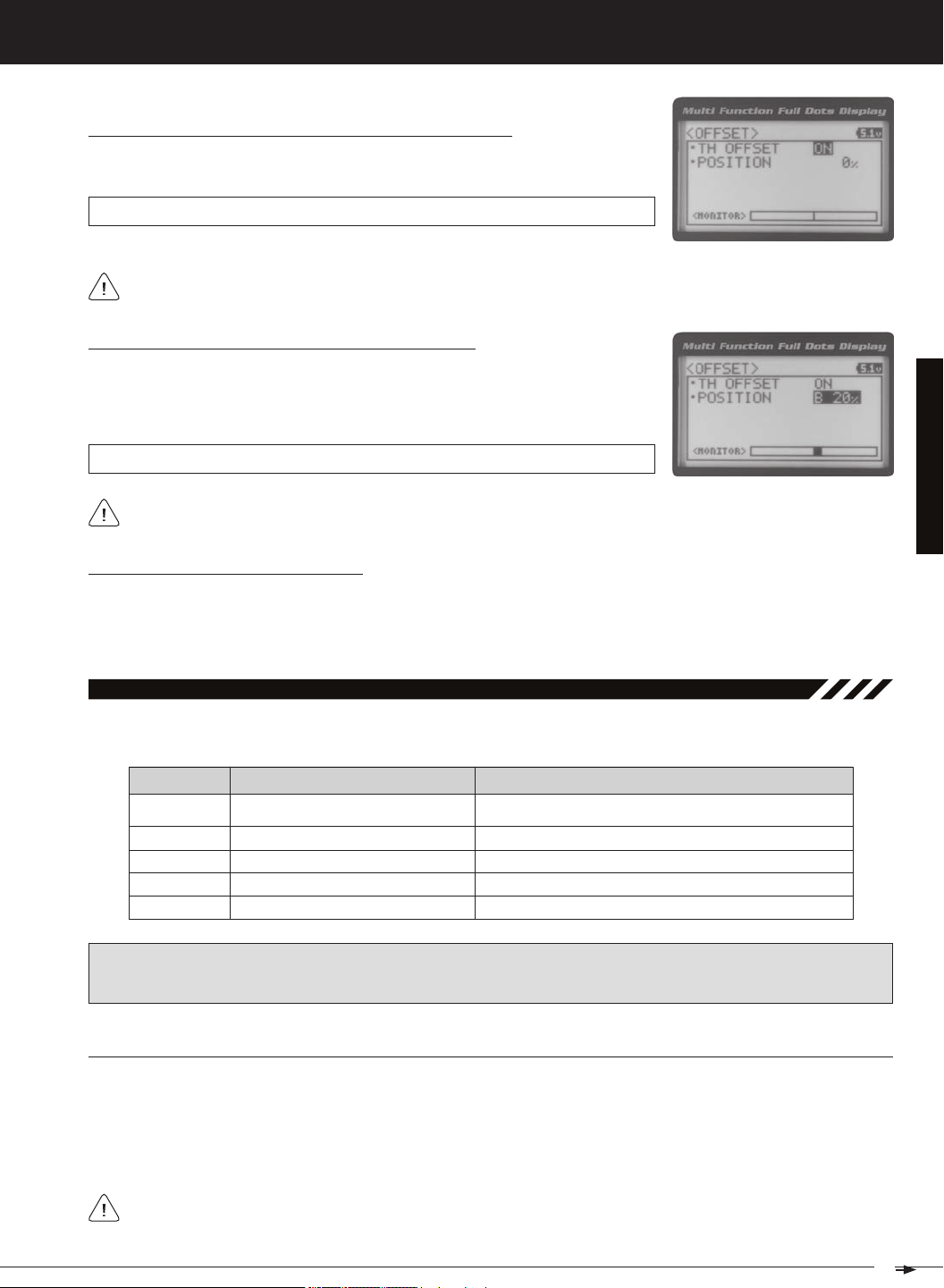
Turning the Throttle Offset Function ON or OFF, Continued....
3) Press the ENTER key, then scroll UP or DOWN to change the Throttle Offset value
OFFSET TH OFFSET setting range is OFF to ON. The default setting is OFF.
Although the Throttle Offset value is set to ON, the Throttle Offset function will not operate until a Position percent-
Adjusting the Throttle Offset Position Percentage Value
1) From within the OFFSET menu, scroll DOWN to highlight POSITION 0%. Press the
ENTER key, then scroll UP to shift the throttle servo Neutral position the desired
amount toward the Throttle High Side or scroll DOWN to shift the throttle servo
OFFSET POSITION setting range is H100% to B100%. The default setting is 0%.
When a Position percentage value is programmed and the Throttle Offset function is Active, LED 1 (Blue) will flash
Controlling the Throttle Offset Function
1) By assigning the Throttle Offset Position programming function to one of the Trim Switches, Auxiliary Lever or Dial
Knob, this function can be adjusted while driving without accessing the Programming Menu. In addition, the Throttle
Offset function can be Toggled OFF and ON by assigning it to one of the Push-Button Switches. For more information,
08.auX1 (auXiliary 1 ProGraMMinG)
The Auxiliary 1 Programming function allows you to program the five different Auxiliary Programming functions that are
S _ A U X
P _ A U X
4 W S
M O A
IMPORTANT: Prior to programming an Auxiliary 1 Programming function you must first choose the desired Auxiliary Programming function in the SYSTEM AUX TYPE menu. Only one Auxiliary 1 Programming function can be Active
at any given time.
Step Auxiliary
Point Auxiliary
Four Wheel Steering Mixing
Motor On Axle Dual Throttle Mixing
Controls Step Values That the Auxiliary Servo Travels
Controls Specific Points That the Auxiliary Servo Travels
Controls Four Wheel Steering Options
Controls Dual Throttle Options
SteP (SteP auXiliary)
The Step Auxiliary function allows you to program the Auxiliary 1 servo to move a defined amount when toggled ON and
OFF using a Push-Button Switch. For example, if you assign Auxiliary 1 to a Push-Button Switch, then program the Step
Auxiliary percentage value to 50%, the Auxiliary 1 servo will travel from the Neutral position to 50% of travel when the
Push-Button Switch is pressed. Press the Push-Button switch a second time and the Auxiliary 1 servo will travel back to
the Neutral position. This is useful to control simple ON/OFF functions, such as a reverse servo for a transmission or a
The Step Auxiliary Position value can be adjusted while you're driving using one of the four Trim Switches, the
Rotary Dial or the Auxiliary Lever. The Step Auxiliary function can be toggled OFF and ON by assigning Auxiliary 1
27
MT-4S 2.4GHZ FH4T RADIO SYSTEM USER'S GUIDE
[[ProGraMMinG MenuS
SteP (SteP auXiliary), Continued....
Choosing the Step Auxiliary Function
2) Scroll UP or DOWN to highlight the SYSTEM menu, then press the ENTER key.
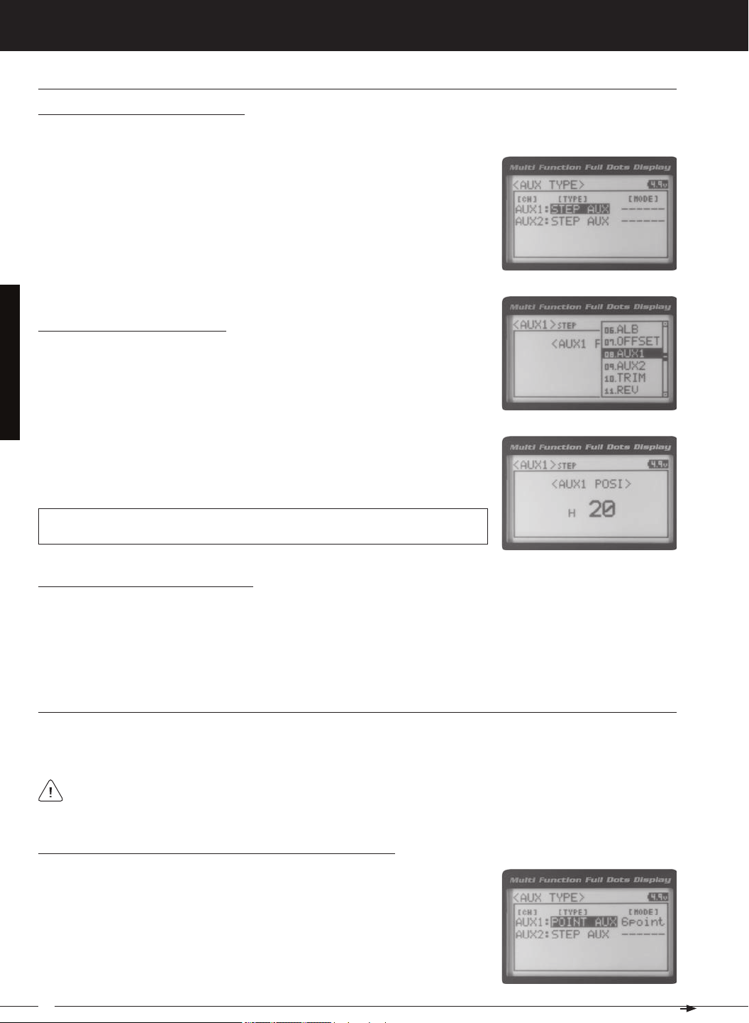
Scroll DOWN to highlight the AUX TYPE menu, then press the ENTER key.
3) Press the ENTER key, then scroll UP or DOWN to choose the AUX 1: STEP AUX
Adjusting the Step Auxiliary Value
1) From the TOP screen, press the ENTER key to open the Programming Menu list.
2) Scroll UP or DOWN to highlight the AUX1 menu, then press the ENTER key. The
3) Press the ENTER key, then scroll UP or DOWN to change the Auxiliary 1 Position
value. Increasing the value toward the High side (H) or Low side (L) will cause
the Auxiliary 1 servo to travel to that specific position when you Activate the Auxil-
AUX1 STEP AUX1 POSI setting range is H100 to L100. The default setting is 0. This
value is a percentage of Auxiliary 1 servo travel.
Controlling the Step Auxiliary Function
1) In the default configuration, Auxiliary 1 is controlled by the Rotary Dial which allows the Step Auxiliary function to be
adjusted while driving without accessing the Programming Menu. Turn the Rotary Dial clockwise to increase the Position High Side value and turn the Rotary Dial counter-clockwise to increase the Position Low Side value. In addition,
Auxiliary 1 can be assigned to one of the four Trim Switches or the Auxiliary Lever. The Step Auxiliary function can
be toggled OFF and ON by assigning Auxiliary 1 to one of the two Push-Button Switches. This allows you to control
Point (Point auXiliary)
The Point Auxiliary function allows you to program the Auxiliary 1 servo to move up to 6 different Points along its travel,
then cycle through those Points using one of the Trim Switches or the Rotary Dial. For example, if your model requires
Use one of the four Trim Switches or the Rotary Dial to cycle through the Point positions while you're driving. The
Point Auxiliary function can be toggled OFF and ON while you're driving by assigning Auxiliary 1 to one of the two
Choosing the Point Auxiliary Function and the Number of Points
2) Scroll UP or DOWN to highlight the SYSTEM menu, then press the ENTER key.
Scroll DOWN to highlight the AUX TYPE menu, then press the ENTER key.
3) Press the ENTER key, then scroll UP or DOWN to choose the AUX 1: POINT AUX
28
T R
MT-4S 2.4GHZ FH4T RADIO SYSTEM USER'S GUIDE
[[ProGraMMinG MenuS
Choosing the Point Auxiliary Function and the Number of Points, Continued....
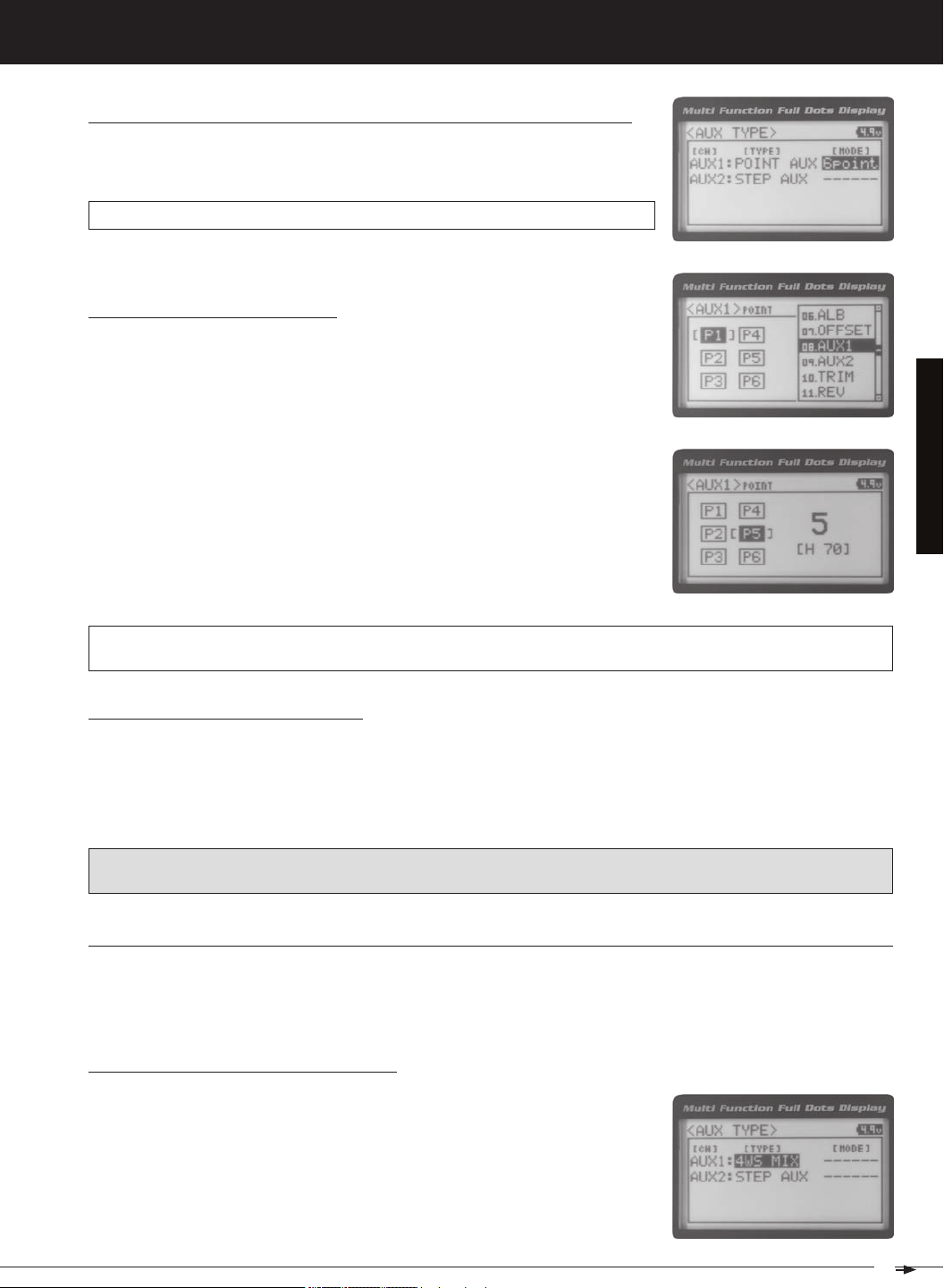
4) From within the AUX TYPE menu, scroll DOWN to highlight [MODE] 6 POINT.
Press the ENTER key, then scroll UP or DOWN to choose the desired number of
AUX TYPE POINT setting range is 2point to 6point. The default setting is 6point.
Adjusting the Point Auxiliary Values
1) From the TOP screen, press the ENTER key to open the Programming Menu list.
2) Scroll UP or DOWN to highlight the AUX1 menu, then press the ENTER key. The
3) Scroll UP or DOWN to move the brackets to the Point you would like to change,
then press the ENTER key to highlight that Point.
4) Press the ENTER key, then scroll UP or DOWN to change the Point value. Increasing the Point value toward the High side (H) or Low side (L) will cause the Auxiliary 1 servo to travel to that specific position when you cycle through the various
Points.
AUX1 POINT setting range is H100 to L100. The default setting for Point 1 is L100, for Point 2 is L60, for Point 3 is L20,
for Point 4 is H20, for Point 5 is H60, and for Point 6 is H100. These values are a percentage of Auxiliary 1 servo travel.
Controlling the Point Auxiliary Function
1) In the default configuration, Auxiliary 1 is controlled by the Rotary Dial. Turn the Rotary Dial clockwise to cycle Forward through the programmed Point Auxiliary positions and turn the Rotary Dial counter-clockwise to cycle Backward
through the programmed Point Auxiliary positions. The Auxiliary 1 servo will move to the specified Point positions as
you cycle through the different Points. In addition, Auxiliary 1 can be assigned to one of the four Trim Switches. The Point
Auxiliary function can be toggled OFF and ON by assigning Auxiliary 1 to one of the two Push-Button Switches. For
IMPORTANT: To operate correctly, the TRIM or DIAL Step value must be set to 1. If set to a value other than 1, Point
positions will be skipped as you cycle through them. For more information, see the Key Assignments section on pages
4wS (four wHeel SteerinG MiXinG)
The Four Wheel Steering Mixing function allows you to use Auxiliary 1 Channel 3 as a second steering channel, allowing
you to use two separate steering servos for Front and Rear steering. The Four Wheel Steering Mixing function allows you
to control either the Front or Rear steering independently, or Mix the Front and Rear steering to have Parallel Four Wheel
Choosing the Four Wheel Steering Function
2) Scroll UP or DOWN to highlight the SYSTEM menu, then press the ENTER key.
Scroll DOWN to highlight the AUX TYPE menu, then press the ENTER key.
29
MT-4S 2.4GHZ FH4T RADIO SYSTEM USER'S GUIDE
[[ProGraMMinG MenuS
4wS (four wHeel SteerinG MiXinG), Continued....
Use the Rotary Dial or one of the four Trim Switches to cycle through the different Four Wheel Steering options
while you're driving. The Four Wheel Steering Mixing function can be toggled OFF and ON while you're driving
PRO TIP: Use the Servo Monitor at the bottom of the AUX 1 4WS menu to see your programming changes in virtual real
Choosing Four Wheel Steering Mixing Options
1) From the TOP screen, press the ENTER key to open the Programming Menu list.
2) Scroll UP or DOWN to highlight the AUX1 menu, then press the ENTER key. The
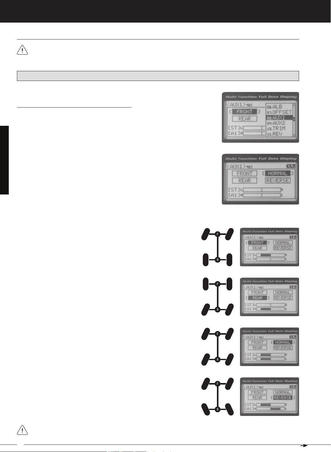
3) Scroll UP or DOWN to move the brackets to the Four Wheel Steering option you
would like to use, then press the ENTER key to highlight that option. The high-
Parallel (Normal) Four Wheel Steering - When highlighted, both the Front
Tandem (Reverse) Four Wheel Steering - When highlighted, both the
If the steering servos do not operate as described above, you can use the Servo Reversing function to change the
30
T R
MT-4S 2.4GHZ FH4T RADIO SYSTEM USER'S GUIDE
[[ProGraMMinG MenuS
4wS (four wHeel SteerinG MiXinG), Continued....
Controlling the Four Wheel Steering Mixing Function
1) In the default configuration, Auxiliary 1 is controlled by the Rotary Dial. Turn the Rotary Dial clockwise to cycle Forward
through the Four Wheel Steering options (FRONT > REAR > NORMAL > REVERSE) and turn the Rotary Dial counterclockwise to cycle Backward through the Four Wheel Steering options (REVERSE > NORMAL > REAR > FRONT). In
addition, Auxiliary 1 can be assigned to one of the four Trim Switches. The Four Wheel Steering Mixing function can
be toggled OFF and ON by assigning Auxiliary 1 to one of the two Push-Button Switches. For more information, see
IMPORTANT: To operate correctly, the DIAL or TRIM Step value must be set to 1. If set to a value other than 1, Four
Wheel Steering Mixing options will be skipped as you cycle through them. For more information, see the Key Assignments section on pages 56 ~ 61.
When using Four Wheel Steering, it's important to adjust the Steering Channel 1 and Auxiliary 1 Channel 3 SubTrim values to center both servos. This will ensure that your model tracks straight. In addition, remember that you
are able to independently adjust the Auxiliary 1 Channel 3 Dual Rate, Exponential, Sub-Trim, Servo Speed settings and
Moa (Motor on aXle MiXinG)
The Motor on Axle Mixing function allows you to use Auxiliary 1 Channel 3 as a second throttle channel, allowing you to
use two separate throttle servos or ESCs. The Motor on Axle Mixing function is typically used in Rock Crawling and allows
you to control either the Front and Rear motors together or independently, giving you Normal (Balanced), Dig and Burn
functions. And when
coupled with the ability to variably change the power distribution between the Front and Rear mo-
Use the Rotary Dial, one of the four Trim Switches or the Auxiliary Lever to Activate the Dig and Burn functions while
you're driving. The Motor on Axle Mixing function can be toggled OFF and ON while you're driving by assigning
PRO TIP: Use the Servo Monitor at the bottom of the AUX 1 MOA menu to see your programming changes in virtual real
Choosing the Motor on Axle Function
1) From the TOP screen, press the ENTER key to open the Programming Menu list.
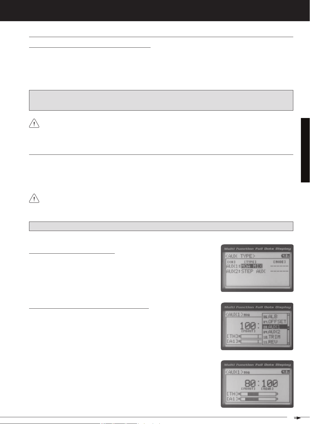
2) Scroll UP or DOWN to highlight the SYSTEM menu, then press the ENTER key.
Scroll DOWN to highlight the AUX TYPE menu, then press the ENTER key.
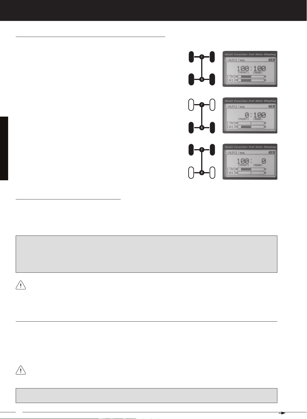
Changing Motor on Axle Power Distribution Options
You are able to program Normal (Balanced), Dig and Burn functions by changing
the Power Distribution between the two motors.
1) From the TOP screen, press the ENTER key to open the Programming Menu list.
2) Scroll UP or DOWN to highlight the AUX1 menu, then press the ENTER key. The
3) Press the ENTER key, then scroll UP or DOWN to change the Power Distribution
between the Front and Rear motors. Scrolling UP will reduce the available power
31
MT-4S 2.4GHZ FH4T RADIO SYSTEM USER'S GUIDE
[[ProGraMMinG MenuS
Changing Motor on Axle Power Distribution Options, Continued....
Normal (Balanced) - When set to 100:100, power will be evenly distributed
Front Throttle BURN - When set to 0:100, power will only be distributed to
the Rear motor (Burn). Power can be distributed proportionally between the
Rear Throttle DIG - When set to 100:0, power will only be distributed to the
Front motor (Dig). Power can be distributed proportionally between the
Controlling the Motor on Axle Mixing Function
1) In the default configuration, Auxiliary 1 is controlled by the Rotary Dial. Turn the Rotary Dial clockwise to reduce the
available power to the Rear motor (Dig) and turn the Rotary Dial counter-clockwise to reduce the power to the Front
motor (Burn). In addition, Auxiliary 1 can be assigned to one of the four Trim Switches or to the Auxiliary Lever. The
Motor on Axle Mixing function can be toggled OFF and ON by assigning Auxiliary 1 to one of the two Push-Button
IMPORTANT: In the default configuration, the Rotary Dial Step value is set to 5. This allows you to adjust the Power Distribution in 5 percent increments. If you prefer to control the Dig and Burn functions as if they were assigned to an ON/
OFF switch, change the DIAL Step value to 100. Alternately, the Motor on Axle Mixing function can be controlled by
the Auxiliary Lever. This allows you to quickly switch between the Dig and Burn functions and still have the ability to
variably change the Power Distribution between the Front and Rear motors. To set this up, change the Auxiliary Lever
Function to AUX1, then change the TWEAK (H) value to +100 and the TWEAK (L) value to -100. For more information,
When using the Motor on Axle function, it's important to adjust the Throttle Channel 2 and Auxiliary 1 Channel 3
Sub-Trim values so both motors' idle (or OFF) settings are equal. This will ensure correct function. In addition,
remember that you are able to independently adjust the Auxiliary 1 Channel 3 Dual Rate, Exponential, Sub-Trim, Servo
auX MiX (auXiliary MiXinG)
The Auxiliary Mixing function allows you to Mix either Steering Channel 1 or Throttle Channel 2 to Auxiliary 1 Channel 3,
while maintaining separate Sub-Trim, End Point Adjustments, Servo Reversing and other channel-specific settings.
The Auxiliary Mixing function is used when a custom Mix is necessary. For example, if your monster truck features dual
Front steering servos, instead of using a Y-Harness to join the two steering servos together, you can use Steering Mixing
to operate both steering servos together and still be able to make adjustments to each servo separately. In addition, if
The Auxiliary Mixing Rate percentage value can be adjusted while you're driving using one of the four Trim
Switches, the Rotary Dial or the Auxiliary Lever. The Auxiliary Mixing function can be toggled OFF and ON while
PRO TIP: Use the Servo Monitor at the bottom of the AUX 1 AUX MIX menu to see your programming changes in virtual
real time.
32
T R
MT-4S 2.4GHZ FH4T RADIO SYSTEM USER'S GUIDE
[[ProGraMMinG MenuS
auX MiX (auXiliary MiXinG), Continued....
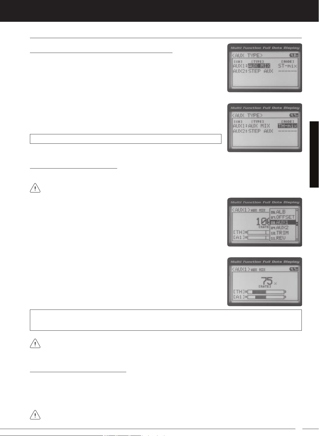
Choosing the Auxiliary Mixing Function and the Mixing Type
1) From the TOP screen, press the ENTER key to open the Programming Menu list.
2) Scroll UP or DOWN to highlight the SYSTEM menu, then press the ENTER key.
Scroll DOWN to highlight the AUX TYPE menu, then press the ENTER key.
4) From within the AUX TYPE menu, scroll DOWN to highlight [MODE] ST-mix. Press
the ENTER key, then scroll UP or DOWN to choose the desired Mixing type you
AUX TYPE MIX setting range is ST-mix and TH-mix. The default setting is ST-mix.
Adjusting the Rate Percentage Value
The Master channel (either Steering Channel 1 or Throttle Channel 2) always controls the Slave channel (Auxil-
1) From the TOP screen, press the ENTER key to open the Programming Menu list.
2) Scroll UP or DOWN to highlight the AUX1 menu, then press the ENTER key. The
3) Press the ENTER key, then scroll UP or DOWN to change the Rate percentage
value. Decreasing the Rate percentage value will reduce the amount the Auxiliary
1 servo travels relative to the Steering servo or Throttle servo and increasing
the Rate percentage value will increase the amount the Auxiliary 1 servo travels
AUX1 AUX MIX RATE setting range is 100% to 0%. The default setting is 100%. This Mix is Linear. For example, if the Rate
percentage value is set to 100%, the Auxiliary 1 servo will travel the same amount as the Steering servo. Additionally, if
the Rate percentage value is set to 50%, the Auxiliary 1 servo will travel half the amount as the Steering servo.
In the default configuration, the Auxiliary 1 servo will travel in the same direction as the Steering servo or Throttle
servo. To apply the Mix in the opposite direction, change the Servo Reversing value of Auxiliary 1 Channel 3. For
Controlling the Auxiliary Mixing Function
1) In the default configuration, Auxiliary 1 is controlled by the Rotary Dial. Turn the Rotary Dial clockwise to increase the
Rate percentage value and turn the Rotary Dial counter-clockwise to decrease the Rate percentage value. In addition,
the Auxiliary Mixing Rate function can be assigned to one of the four Trim Switches or the Auxiliary Lever. The Auxiliary
Mixing function can be toggled OFF and ON by assigning Auxiliary 1 to one of the two Push-Button Switches. For
Remember that you are able to independently adjust the Auxiliary 1 Channel 3 Dual Rate, Exponential, Sub-Trim,
33
MT-4S 2.4GHZ FH4T RADIO SYSTEM USER'S GUIDE
[[ProGraMMinG MenuS
09.auX2 (auXiliary 2 ProGraMMinG)
The Auxiliary 2 Programming function allows you to program the five different Auxiliary Programming functions that are
S _ A U X
P _ A U X
4 W S
M O A
IMPORTANT: Prior to programming an Auxiliary 2 Programming function you must first choose the desired Auxiliary Programming function in the SYSTEM AUX TYPE menu. Only one Auxiliary 2 Programming function can be Active
at any given time.
Step Auxiliary
Point Auxiliary
Four Wheel Steering Mixing
Motor On Axle Dual Throttle Mixing
Controls Step Values That the Auxiliary Servo Travels
Controls Specific Points That the Auxiliary Servo Travels
Controls Four Wheel Steering Options
Controls Dual Throttle Options
SteP (SteP auXiliary)
The Step Auxiliary function allows you to program the Auxiliary 2 servo to move a defined amount when toggled ON and
OFF using a Push-Button Switch. For example, if you assign Auxiliary 2 to a Push-Button Switch, then program the Step
Auxiliary percentage value to 50%, the Auxiliary 2 servo will travel from the Neutral position to 50% of travel when the
Push-Button Switch is pressed. Press the Push-Button switch a second time and the Auxiliary 2 servo will travel back to
the Neutral position. This is useful to control simple ON/OFF functions, such as a reverse servo for a transmission or a
The Step Auxiliary Position value can be adjusted while you're driving using one of the four Trim Switches, the
Rotary Dial or the Auxiliary Lever. The Step Auxiliary function can be toggled OFF and ON by assigning Auxiliary 2
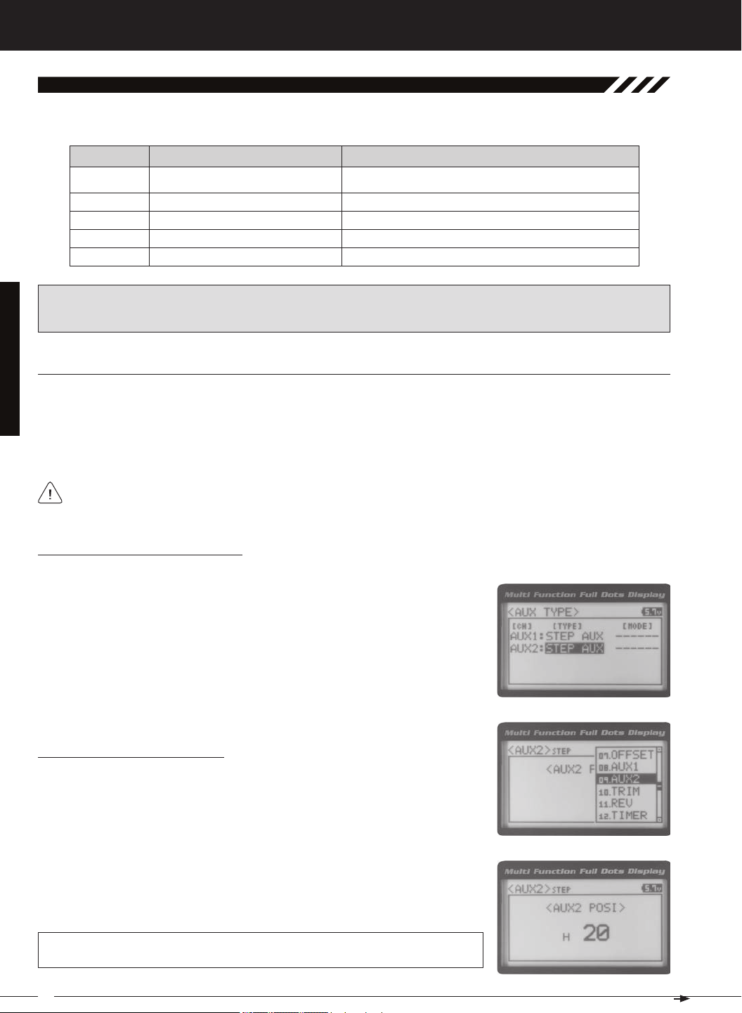
Choosing the Step Auxiliary Function
2) Scroll UP or DOWN to highlight the SYSTEM menu, then press the ENTER key.
Scroll DOWN to highlight the AUX TYPE menu, then press the ENTER key.
3) Press the ENTER key, then scroll UP or DOWN to choose the AUX 2: STEP AUX
Adjusting the Step Auxiliary Value
1) From the TOP screen, press the ENTER key to open the Programming Menu list.
2) Scroll UP or DOWN to highlight the AUX2 menu, then press the ENTER key. The
3) Press the ENTER key, then scroll UP or DOWN to change the Auxiliary 2 Position
value. Increasing the value toward the High side (H) or Low side (L) will cause
the Auxiliary 2 servo to travel to that specific position when you Activate the Auxil-
AUX2 STEP AUX2 POSI setting range is H100 to L100. The default setting is 0. This
value is a percentage of Auxiliary 2 servo travel.
34
T R
MT-4S 2.4GHZ FH4T RADIO SYSTEM USER'S GUIDE
[[ProGraMMinG MenuS
SteP (SteP auXiliary), Continued....
Controlling the Step Auxiliary Function
1) In the default configuration, Auxiliary 2 is controlled by the Rotary Dial which allows the Step Auxiliary function to be
adjusted while driving without accessing the Programming Menu. Turn the Rotary Dial clockwise to increase the Position High Side value and turn the Rotary Dial counter-clockwise to increase the Position Low Side value. In addition,
Auxiliary 2 can be assigned to one of the four Trim Switches or the Auxiliary Lever. The Step Auxiliary function can
be toggled OFF and ON by assigning Auxiliary 2 to one of the two Push-Button Switches. This allows you to control
Point (Point auXiliary)
The Point Auxiliary function allows you to program the Auxiliary 2 servo to move up to 6 different Points along its travel,
then cycle through those Points using one of the Trim Switches or the Rotary Dial. For example, if your model requires
Use one of the four Trim Switches or the Rotary Dial to cycle through the Point positions while you're driving. The
Point Auxiliary function can be toggled OFF and ON while you're driving by assigning Auxiliary 2 to one of the two
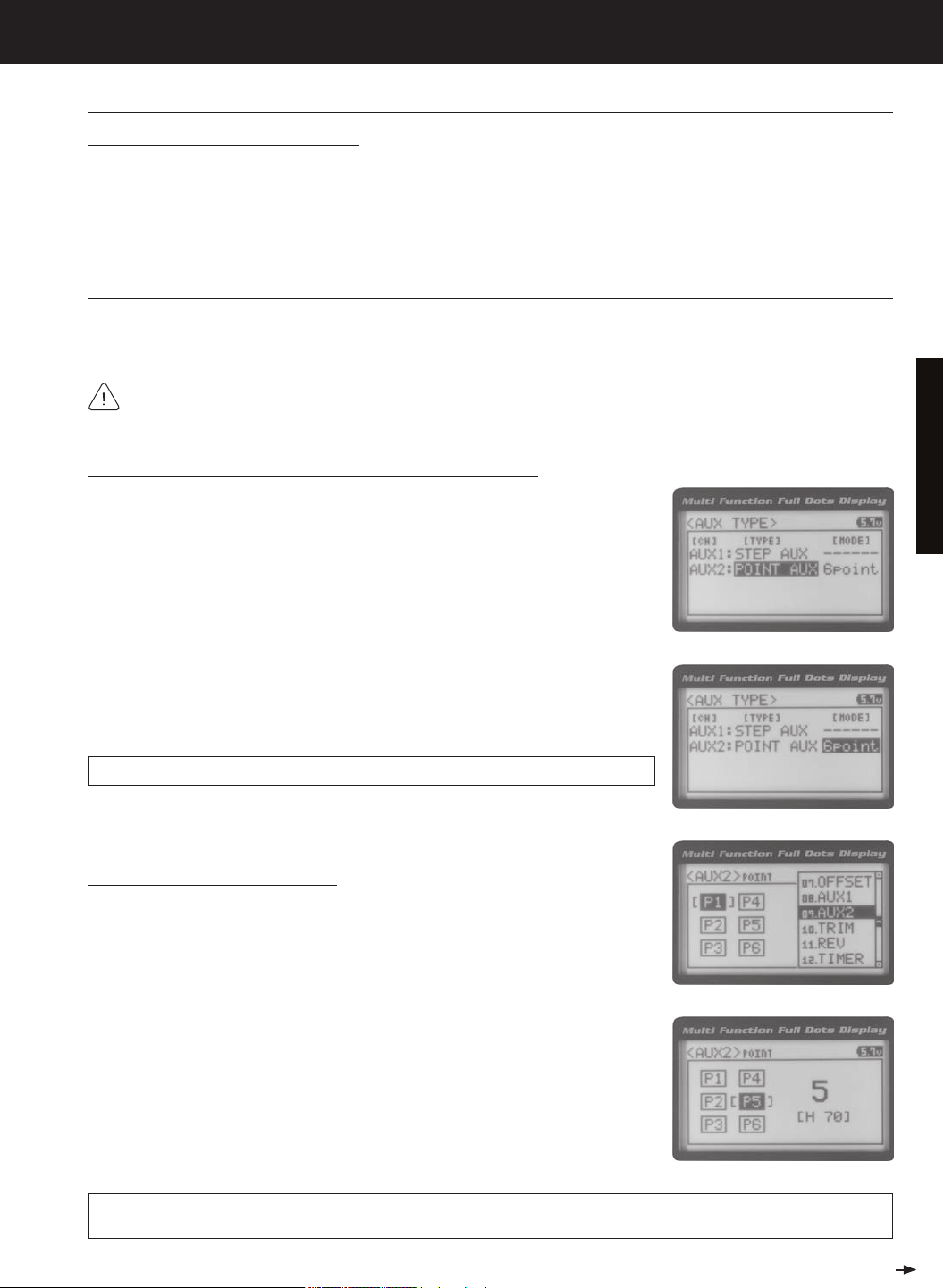
Choosing the Point Auxiliary Function and the Number of Points
2) Scroll UP or DOWN to highlight the SYSTEM menu, then press the ENTER key.
Scroll DOWN to highlight the AUX TYPE menu, then press the ENTER key.
3) Press the ENTER key, then scroll UP or DOWN to choose the AUX 2: POINT AUX
4) From within the AUX TYPE menu, scroll DOWN to highlight [MODE] 6 POINT.
Press the ENTER key, then scroll UP or DOWN to choose the desired number of
AUX TYPE POINT setting range is 2point to 6point. The default setting is 6point.
Adjusting the Point Auxiliary Values
1) From the TOP screen, press the ENTER key to open the Programming Menu list.
2) Scroll UP or DOWN to highlight the AUX1 menu, then press the ENTER key. The
3) Scroll UP or DOWN to move the brackets to the Point you would like to change,
then press the ENTER key to highlight that Point.
4) Press the ENTER key, then scroll UP or DOWN to change the Point value. Increasing the Point value toward the High side (H) or Low side (L) will cause the Auxiliary 2 servo to travel to that specific position when you cycle through the various
Points.
AUX2 POINT setting range is H100 to L100. The default setting for Point 1 is L100, for Point 2 is L60, for Point 3 is L20,
for Point 4 is H20, for Point 5 is H60, and for Point 6 is H100. These values are a percentage of Auxiliary 2 servo travel.
35
 Loading...