

Sanwa Electronic Instrument Co 90486 User Manual
M12S 2.4GHZ FH4T RADIO CONTROL SYSTEM USER'S GUIDE
TR
BATT MENU {LOW VOLTAGE ALERT AND LIMIT ALARMS
}
SYSTEM
Changing the Low Voltage Alert Alarm Value:
The Low Voltage Alert alarm will sound to indicate the transmitter batteries are getting low and should be replaced or recharged.
We suggest stopping use as soon as safely possible and replacing or recharging the transmitter batteries. The Low Voltage Alert
alarm will sound for approximately 5 seconds each time the transmitter battery voltage decreases by 0.1 volt. To clear this alarm
before it turns off automatically, press the BACK key or the ENTER key.
1) From within the SYSTEM menu, scroll UP or DOWN to highlight the BATT
menu.
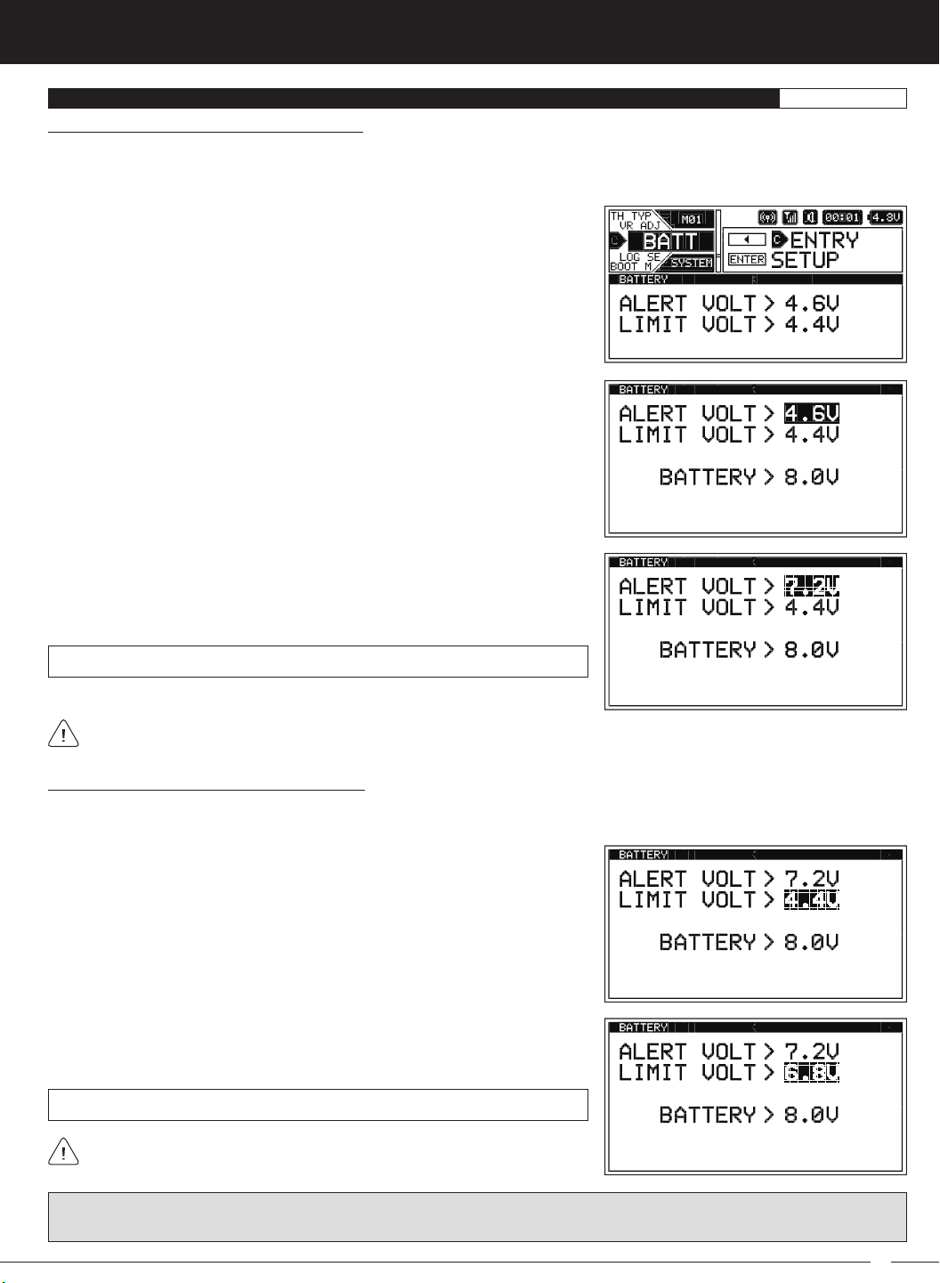
2) Press the ENTER key to open the BATT menu. ALERT VOLT > 4.6V will be
highlighted and the current transmitter battery voltage will be displayed.
3) Press the ENTER key, then scroll UP or DOWN to choose the desired Low Voltage Alert alarm voltage value. We suggest using the value listed in the table
on the previous page that matches the type of transmitter battery you're using.
ALERT VOLT setting range is 4.4V to 9.0V. The default setting is 4.6V.
The Low Voltage Alert alarm voltage value cannot be set Lower than the Low Voltage Limit alarm voltage value.
Changing the Low Voltage Limit Alarm Value:
The Low Voltage Limit alarm will sound to indicate the transmitter batteries are dangerously low and should be replaced or
recharged Right away. The Low Voltage Limit alarm cannot be cancelled. When the Low Voltage Limit alarm sounds, you should
stop use as soon as it's safe, then replace or recharge the transmitter batteries.
1) From within the BATT menu, scroll UP or DOWN to highlight LIMIT VOLT > 4.4V.
2) Press the ENTER key, then scroll UP or DOWN to choose the desired Low
Voltage Limit alarm value. We suggest using the value listed in the table on
the previous page that matches the type of transmitter battery you're using.
LIMIT VOLT setting range is 4.0v to 9.0v. The default setting is 4.4V.
The Low Voltage Limit alarm voltage value cannot be set Higher than the
Low Voltage Alert alarm voltage value.
WARNING: Continuing to use the transmitter after the Low Voltage Limit alarm sounds can result in loss of control of your
Model. When the Low Voltage Limit alarm sounds, stop use as soon as is safe, then replace or recharge the transmitter batteries.
47
M12S 2.4GHZ FH4T RADIO CONTROL SYSTEM USER'S GUIDE
LOG SETUP MENU {TELEMETRY DISPLAY AND RECORDING OPTIONS
}
SYSTEM
The LOG SETUP menu allows you to turn Telemetry Recording ON and OFF and configure how Telemetry Data is displayed on
the TELEMETRY screen. For example, you are able to change the Telemetry Temperature reading from Fahrenheit to Celsius,
change the values at which the different Telemetry Sensor alarms sound, change how Speed and RPM are displayed and
much more.
In addition, when only the DISPLAY is turned ON using the DISPLAY key, the M12S can be placed in Receiver Mode, allowing it to
Bind with another Airtronics FH3 or FH4T transmitter and read Telemetry Data from it. For example, if using an FH4T transmitter
like the MT-4, MT-4 Telemetry Data can be viewed on the M12S TELEMETRY screen, or, if using an FH3 transmitter like the MX-3X
or M11X that doesn't support Telemetry, Steering and Throttle Output Data can still be viewed on the M12S TELEMETRY screen.
This capability allows the M12S to be used as a separate Telemetry Viewer and Recorder, much like the Airtronics TLS-01
Telemetry Logger.
For information about saving Telemetry Data to a PC, see the
TELEMETRY screen and viewing Telemetry Data, see the
PC
LINK
Menu
section on page 58. For information about using the
TELEMETRY Screen Overview
section on pages 21 ~ 22.
IMPORTANT: Full Telemetry integration requires the use of an Airtronics RX-461, RX-462 or other Airtronics FH4T Telemetry
receiver (available separately), although Throttle and Steering Output Data can still be viewed on the TELEMETRY screen and
recorded if using an FH2, FH3 or FH4 receiver.
For information about using an optional Telemetry receiver with your M12S transmitter, plugging the Telemetry Sensors into
your receiver and installing them into your Model, see the
Telemetry Data Recording
Telemetry Connections and Mounting
section on pages 96 ~ 97.
The Telemetry Data Recording function records Telemetry Data when the Lap Timer is Started. When the Lap Timer is Stopped,
Telemetry Recording is also Stopped. One Telemetry Data Log is kept in memory at a time and will be available for viewing even
after the transmitter is turned OFF. When the Lap Timer is Started again, the current Telemetry Data Log will be erased and a new
one Started. If you want to Save the current Telemetry Data Log, use the Save Log option in the PC
LINK menu.
Turning Telemetry Data Recording ON and OFF:
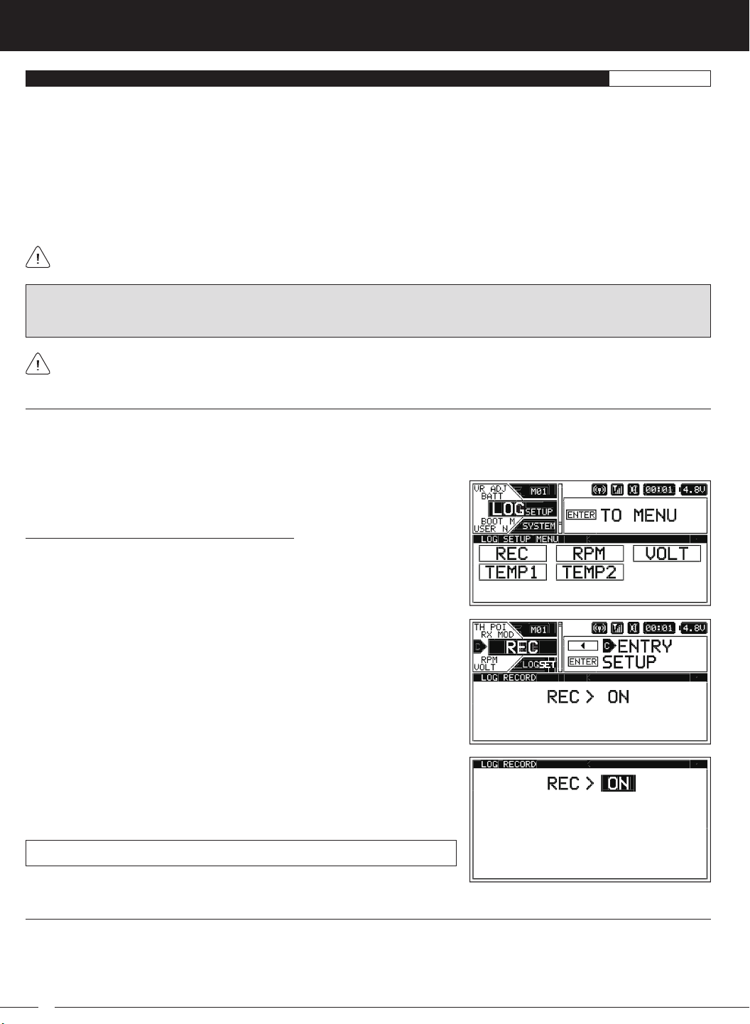
1) From within the SYSTEM menu, scroll UP or DOWN to highlight the LOG SETUP
menu.
2) Press the ENTER key to open the LOG SETUP menu, then scroll UP or DOWN
to highlight the REC menu.
3) Press the ENTER key to open the REC menu. REC > ON will be highlighted.
4) Scroll UP or DOWN to choose the desired Record value, either ON or OFF.
When ON is chosen, Telemetry Data will be Recorded. When OFF is chosen,
Telemetry Data will not be Recorded.
REC setting range is ON or OFF. The default setting is ON.
RPM and Speed Telemetry Data Display Options
The RPM menu allows you to change the way RPM and Speed information is displayed on the TELEMETRY screen ALL and RPM
pages. For example, you can choose to display RPMs, MPH or KM/H. The RPM Gauge and the RPM Digital Display names will
even change from RPM to MPH or KM/H depending on the RPM Unit value chosen. On top of that, you can choose the Maximum
Telemetry Data values that are displayed and the RPM sensor can be calibrated to ensure the most accurate RPM or speed in
MPH or KM/H is displayed for your specific Model.
48
M12S 2.4GHZ FH4T RADIO CONTROL SYSTEM USER'S GUIDE
TR
LOG SETUP MENU {TELEMETRY DISPLAY AND RECORDING OPTIONS
Changing the RPM Unit Value:
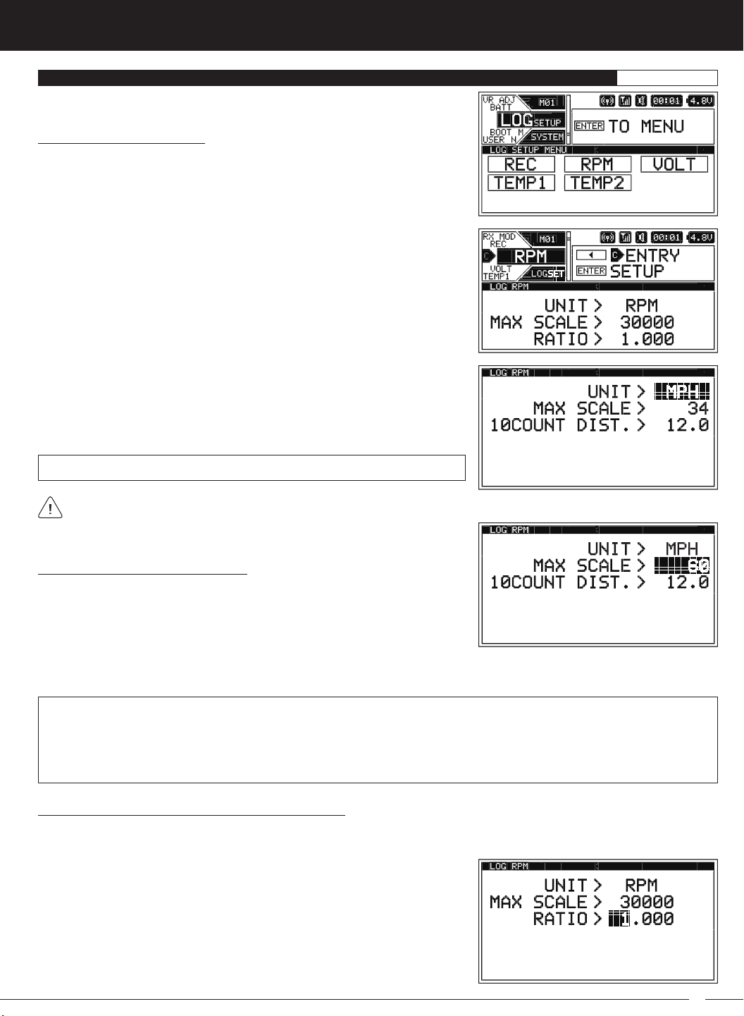
1) From within the SYSTEM menu, scroll UP or DOWN to highlight the LOG SETUP
menu.
2) Press the ENTER key to open the LOG SETUP menu, then scroll UP or DOWN
to highlight the RPM menu.
3) Press the ENTER key to open the RPM menu. UNIT > RPM will be highlighted.
4) Press the ENTER Key, then scroll UP or DOWN to change the RPM Unit to the
desired value. When RPM is chosen, the RPM of whatever the RPM Sensor is
attached to will be displayed. When MPH or KM/H is chosen, the speed of your
Model will be displayed in either MPH or KM/H, respectively.
UNIT setting range is RPM, MPH and KM/H. The default setting is RPM.
}
SYSTEM
When you choose UNIT > MPH or UNIT > KM/H the RATIO > value will be replaced with a 10COUNT DIST. > value.
Changing the Maximum Scale Value:
1) From within the RPM menu, scroll UP or DOWN to highlight the MAX SCALE >
value. This value will vary depending on the UNIT > value chosen previously.
2) Press the ENTER key, then scroll UP or DOWN to change the Maximum Scale value. This value determines the maximum
RPM, MPH or KM/H value that will be displayed on the TELEMETRY screen ALL and RPM pages.
MAX SCALE setting range is 500 to 127500 RPM, 1 to 999 MPH and 1 to 999 KM/H. The default setting is 30000 RPM, 34 MPH
and 54 KM/H.
The Maximum Scale MPH and KM/H setting range will vary based on the 10Count Distance value programmed when you
calibrate the RPM Sensor. For more information, see the
Calibrating the RPM Sensor - Changing the 10Count Distance Value
section on page 50.
Calibrating the RPM Sensor - Changing the Ratio Value:
The Ratio value can be changed if you've Selected UNIT > RPM. By changing the Ratio value you are able to read actual motor or
engine RPM even though the RPM sensor may be mounted to your Model's spur gear and not to the motor's pinion gear or the
engine's flywheel.
1) From within the RPM menu and with UNIT > RPM Selected, scroll UP or
DOWN to highlight RATIO > 1.000.
49
M12S 2.4GHZ FH4T RADIO CONTROL SYSTEM USER'S GUIDE
LOG SETUP MENU {TELEMETRY DISPLAY AND LOGGING OPTIONS
}
SYSTEM
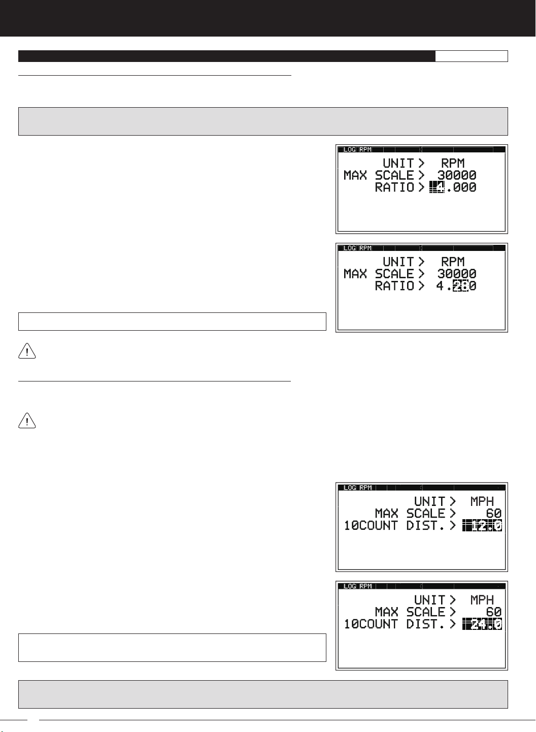
Calibrating the RPM Sensor - Changing the Ratio Value, Continued....
The Ratio value is the gear ratio between the two gears that the RPM sensor is mounted to. For example, if the RPM sensor is
mounted to your spur gear, the Ratio value will be the gear ratio of your spur gear and pinion gear.
IMPORTANT: To calculate the gear ratio, divide the number of teeth in the spur gear by the number of teeth in the pinion gear.
For example, if your spur gear is 60T and your pinion gear is 14T, the gear ratio is 60 / 14 = 4.28.
2) Press the ENTER key, then scroll UP or DOWN to choose the desired first Ratio
value. If using the example above, choose 4.
3) Press the ENTER key, then scroll DOWN to highlight the second Ratio
value. Press the ENTER key, then scroll UP or DOWN to choose the desired
second Ratio value. If using the example above, choose 28.
4) If necessary, press the ENTER key, then scroll DOWN to highlight the third
ratio value. Press the ENTER key, then scroll UP or DOWN to choose the
desired third Ratio value.
RATIO setting range is 1.000 to 64.999. The default setting is 1.000.
If the RPM sensor is mounted to your engine's flywheel or your motor's pinion gear to read the RPM directly, the Ratio value
should be set to 1.000.
Calibrating the RPM Sensor - Changing the 10Count Distance Value:
The 10Count Distance value can be changed if you've Selected UNIT > MPH or UNIT > KM/H. By changing the 10Count Distance
value you are able to calibrate the RPM sensor to read your specific Model's actual speed, in either MPH or KM/H.
Prior to calibrating the RPM sensor, you must connect the RPM sensor to your receiver and correctly install the RPM sensor
into your Model. For more information, see the
Telemetry Connections and Mounting
section on pages 96 ~ 97.
1) With your transmitter and receiver turned ON, and with an Active Telemetry connection, place your Model on the ground.
2) Measuring in inches (or centimeters if using KM/H) from where you set your Model on the ground, slowly push your Model
and measure the distance covered to complete 10 full revolutions of the RPM sensor (the Bind LED on your receiver will flash
10 times, indicating 10 full revolutions).
3) From within the RPM menu and with UNIT > MPH or UNIT > KM/H Selected,
scroll UP or DOWN to highlight 10COUNT DIST > 12.0 or 10COUNT DIST > 30,
depending on the UNIT > value Selected previously.
4) Press the ENTER key, then scroll UP or DOWN to change the 10Count Distance
value to match the measurement obtained in step 2 above. For example, if
your Model traveled 2 feet (61cm) to complete 10 full revolutions, enter 24.0
(for MPH) or 61 (for KM/H).
10COUNT DIST setting range is 0.5 to 118.0 for MPH and 1 to 300 for KM/H. The
default setting is 12.0 for MPH and 30 for KH/H.
IMPORTANT: Changing the 10Count Distance value will change the Maximum Scale value. After calibration, you should reset
the Maximum Scale value back to the value you chose previously.
50
M12S 2.4GHZ FH4T RADIO CONTROL SYSTEM USER'S GUIDE
TR
LOG SETUP MENU {TELEMETRY DISPLAY AND LOGGING OPTIONS
Receiver Battery Low Voltage Telemetry Data Display and Alert Alarm Options
}
SYSTEM
The VOLT menu allows you to change the way receiver battery Voltage information is displayed on the TELEMETRY screen ALL
and VOLT pages and when the receiver battery Low Voltage Alert alarm sounds. For example, the Maximum Voltage value can
be adjusted to calibrate the VOLT Indicator on the TELEMETRY screen ALL page. In addition, you can adjust the Voltage value that
the receiver battery Low Voltage Alert alarm will sound at to match the type of receiver battery you're using.
Changing the Maximum Voltage Value:
1) From within the SYSTEM menu, scroll UP or DOWN to highlight the LOG SETUP
menu.
2) Press the ENTER key to open the LOG SETUP menu, then scroll UP or DOWN
to highlight the VOLT menu.
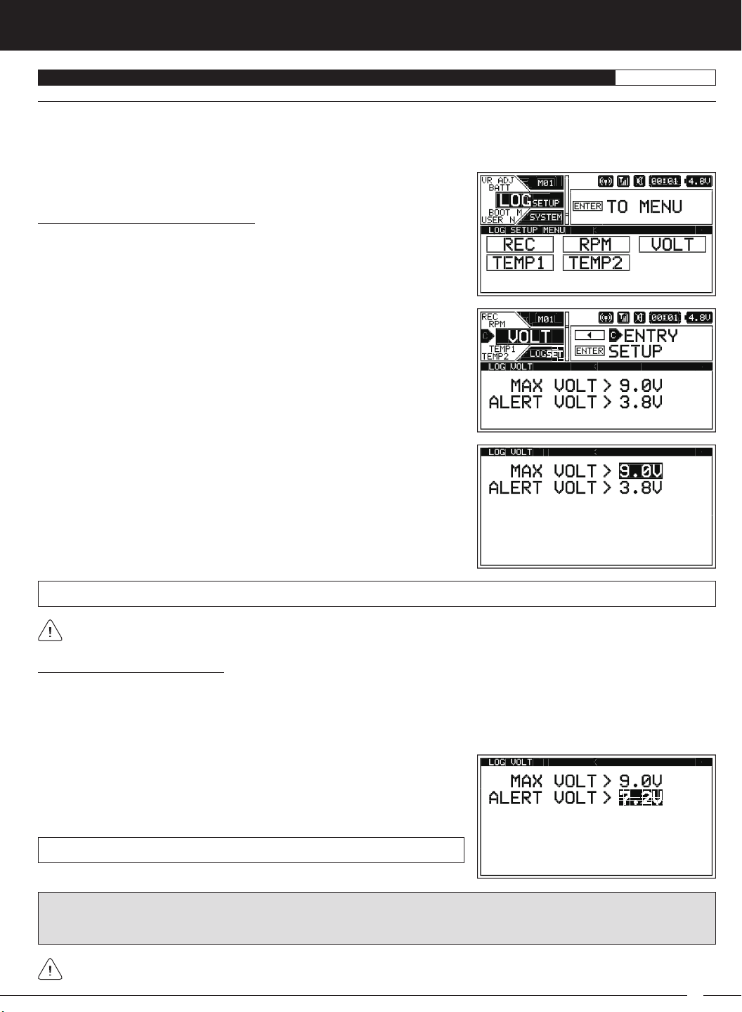
3) Press the ENTER key to open the VOLT menu. MAX VOLT > 9.0V will be
highlighted.
4) Press the ENTER key, then scroll UP or DOWN to choose the desired Maximum
Voltage value. This value determines the Maximum Voltage that will be
displayed on the TELEMETRY screen VOLT page and also calibrates the VOLT
Indicator on the TELEMETRY screen ALL page. We suggest using a value that
matches as closely as possible the peaked voltage value of your receiver
battery after it's pulled off your charger.
MAX VOLT setting range is 3.0V to 9.0V. The default setting is 9.0V.
The Maximum Voltage value cannot be set Lower than the Alert Voltage value. If necessary, you may need to Lower the Alert
Voltage value prior to lowering the Maximum Voltage value.
Changing the Alert Voltage Value:
The Alert Voltage value determines the voltage at which the receiver battery Low Voltage Alert alarm will sound. For example, you
can set the Alert Voltage value to alert you to when your Model's receiver battery is getting low and needs to be recharged. When
the Alert Voltage value is reached, the Voltage Alert alarm will sound and LED2 will flash. The Low Voltage Alert alarm will sound
for approximately 5 seconds, however, LED2 will continue to flash until you recharge the receiver battery. The audible portion of
the Low Voltage Alert alarm can be cleared by pressing the BACK or ENTER keys.
1) From within the VOLT menu, scroll UP or DOWN to highlight ALERT VOLT > 3.8V.
2) Press the ENTER key, then scroll UP or DOWN to change the Alert Voltage
value. The Alert Voltage value is the voltage that the receiver battery Low
Voltage Alert alarm will sound at.
ALERT VOLT setting range is 3.0V to 9.0V. The default setting is 3.8V.
IMPORTANT: Refer to the manufacturer of your Model's receiver battery to determine the safest Alert Voltage value to use. In
general, the Alert Voltage value should be high enough to alert you when it's time to recharge your receiver battery, but not so
low that the receiver can no longer control your Model or operate your servos optimally.
The Alert Voltage value cannot be set Higher than the Maximum Voltage value. If necessary, you may need to raise the
Maximum Voltage value prior to raising the Alert Voltage value.
51
M12S 2.4GHZ FH4T RADIO CONTROL SYSTEM USER'S GUIDE
LOG SETUP MENU {TELEMETRY DISPLAY AND LOGGING OPTIONS
Temperature 1 and Temperature 2 Telemetry Data Display and Alert Alarm Options
}
SYSTEM
The TEMP1 and TEMP2 menus allow you to change the way Temperature information is displayed on the TELEMETRY screen
ALL and TEMP1 and/or TEMP2 pages, and when the Temperature Alert alarm sounds. For example, you can choose to display
Temperature values in either degrees Fahrenheit or degrees Celsius. In addition, the Maximum and Minimum Temperature values
can be adjusted to calibrate the TEMP1 and/or TEMP2 Indicator(s) on the TELEMETRY screen ALL page. You can also adjust the
Temperature value at which the Temperature Alert alarm will sound to suit the component the Temperature sensor is attached to.
This section covers both the TEMP1 and TEMP2 menus, since programming each of them is exactly the same. Choose either
the TEMP1 or the TEMP2 menu depending on which of the two Temperature Sensor Ports you want to make changes to.
Changing the Temperature Unit Value:
1) From within the SYSTEM menu, scroll UP or DOWN to highlight the LOG SETUP
menu.
2) Press the ENTER key to open the LOG SETUP menu, then scroll UP or DOWN
to highlight either the TEMP1 or the TEMP2 menu depending on which of the
two Temperature Sensor Ports you want to make changes to.
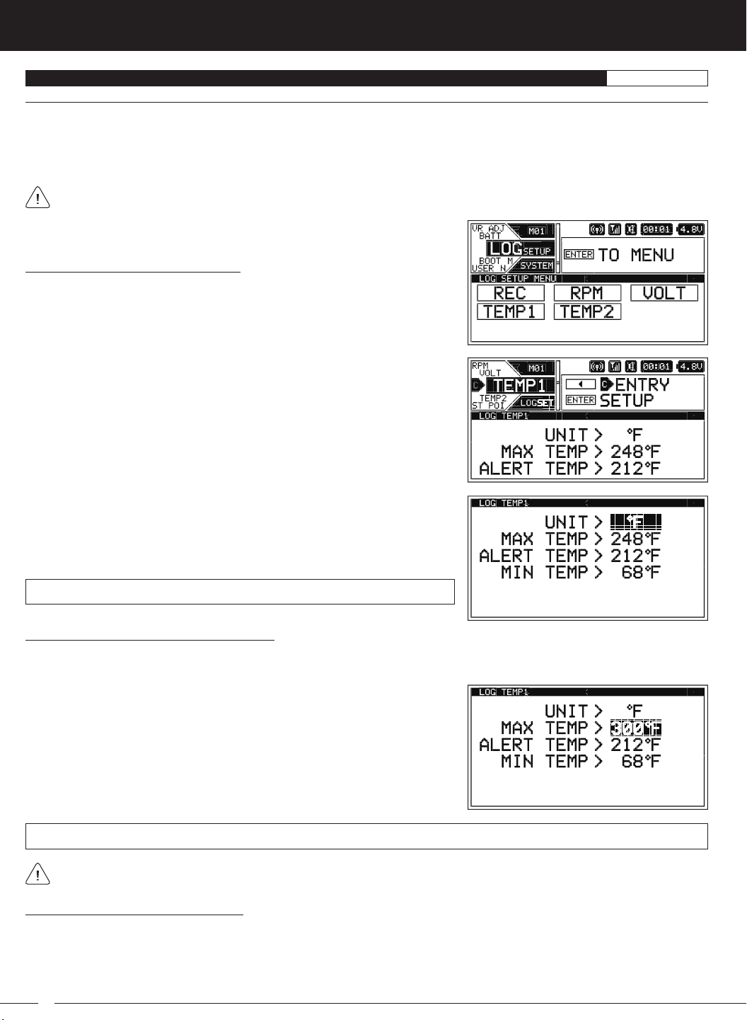
3) Press the ENTER key to open the TEMP1 or TEMP2 menu. UNIT > ºF will be
highlighted.
4) Press the ENTER key, then scroll UP or DOWN to choose the desired Temperature
Unit value, either Fahrenheit or Celsius.
UNIT setting range is ºF and ºC. The default setting is ºF.
Changing the Maximum Temperature Value:
The Maximum Temperature value determines the Maximum Temperature that will be displayed on the TELEMETRY screen
TEMP1 or TEMP2 page and also calibrates the TEMP1 or TEMP2 Indicator on the TELEMETRY screen ALL page.
1) From within the TEMP1 or TEMP2 menu, scroll UP or DOWN to highlight MAX
TEMP > 248ºF (or 120ºC).
2) Press the ENTER key, then scroll UP or DOWN to choose the desired Maximum
Temperature value.
MAX TEMP setting range is 68ºF to 302ºF (0ºC to 150ºC). The default setting is 248ºF (120ºC).
The Maximum Temperature value cannot be set Lower than the Alert Temperature value or the Minimum Temperature value.
If necessary, you may need to Lower the Alert Temperature value prior to lowering the Maximum Temperature value.
Changing the Alert Temperature Value:
The Alert Temperature value determines the temperature at which the Temperature Alert alarm will sound. For example, you can
set an Alert Temperature value for your nitro engine that will alert you when your engine's cylinder head temperature is getting too
hot. When the Alert Temperature value is reached, the Temperature Alert alarm will sound and LED2 will flash. The Temperature
Alert alarm will sound for approximately 5 seconds, however, LED2 will continue to flash until the temperature drops below the
Alert Temperature value. The audible portion of the Temperature Alert alarm can be cleared by pressing the BACK or ENTER keys.
52
M12S 2.4GHZ FH4T RADIO CONTROL SYSTEM USER'S GUIDE
TR
LOG SETUP MENU {TELEMETRY DISPLAY AND LOGGING OPTIONS
}
SYSTEM
Changing the Alert Temperature Value, Continued....
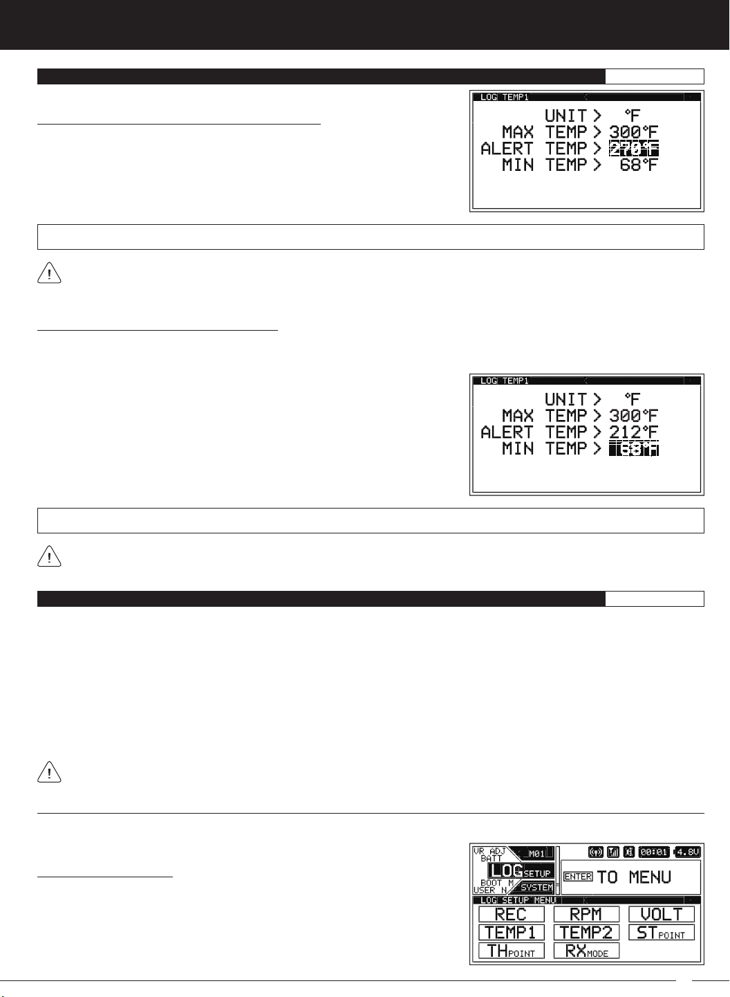
1) From within the TEMP1 or TEMP2 menu, scroll UP or DOWN to highlight
ALERT TEMP 212ºF (or 100ºC).
2) Press the ENTER key, then scroll UP or DOWN to choose the desired Alert
Temperature value.
ALERT TEMP setting range is 68ºF to 302ºF (0ºC to 150ºC). The default setting is 212ºF (100ºC).
The Alert Temperature value cannot be set Higher than the Maximum Temperature value or Lower than the Minimum
Temperature value. If necessary, you may need to Lower the Minimum Temperature value prior to lowering the Alert
Temperature value.
Changing the Minimum Temperature Value:
The Minimum Temperature value determines the Minimum Temperature that will be displayed on the TELEMETRY screen TEMP1
or TEMP2 page and also calibrates the TEMP1 or TEMP2 Indicator on the TELEMETRY screen ALL page.
1) From within the TEMP1 or TEMP2 menu, scroll UP or DOWN to highlight MIN
TEMP > 68ºF (or 20ºC).
2) Press the ENTER key, then scroll UP or DOWN to choose the desired Minimum
Temperature value.
MIN TEMP setting range is 32ºF to 302ºF (0ºC to 150ºC). The default setting is 68ºF (20ºC).
The Minimum Temperature value cannot be set Higher than the Alert Temperature value or the Maximum Temperature
value. If necessary, you may need to Increase these values prior to Increasing the Minimum Temperature value.
LOG SETUP MENU {DISPLAY ONLY TELEMETRY OPTIONS
}
SYSTEM
As described previously, when only the DISPLAY is turned ON using the DISPLAY key, the M12S can be placed in Receiver Mode,
allowing it to Bind with another Airtronics FH3 or FH4T transmitter and read Telemetry Data from it. For example, if using an FH4T
transmitter like the MT-4, MT-4 Telemetry Data can be viewed on the M12S TELEMETRY screen, or, if using an FH3 transmitter like
the MX-3X or M11X that doesn't support Telemetry, Steering and Throttle Output Data can still be viewed on the M12S TELEMETRY
screen. This capability allows the M12S to be used as a separate Telemetry Viewer and Recorder, much like the Airtronics TLS01 Telemetry Logger. To use this feature, first Bind your other transmitter to its receiver, then place the M12S in Receiver Mode
and Bind it to your other transmitter. With your other transmitter turned ON and operating your Model, you can use the M12S in
DISPLAY mode to view Telemetry data from the other transmitter.
This section details placing the M12S in Receiver Mode and making Steering and Throttle Point adjustments so that your paired
transmitter's Steering and Throttle Output Data is displayed correctly on the M12S's TELEMETRY screen.
The menus shown in this section are only available when using the M12S in DISPLAY mode. They are not available if the
M12S is turned ON using the Power Switch.
Receiver Mode
Using the RXMODE menu, you are able to place the M12S transmitter in Receiver Mode, which allows you to Bind the M12S transmitter with another Airtronics FH3 or FH4T transmitter and read Telemetry Data from it.
Enabling Receiver Mode:
1) With the transmitter turned OFF, press and HOLD the DISPLAY key to turn only
the Display ON.
2) From within the SYSTEM menu, scroll UP or DOWN to highlight the LOG SETUP
menu.
53
 Loading...