

Sanwa Electronic Instrument Co 90478 User Manual
TR
90478 2.4GHZ FH4T RADIO SYSTEM USER'S GUIDE
12.TIMER (TRACK TIMERS
)
PROGRAM
Starting the Interval Timer:
1) In the default configuration, Push-Button Switch Sw2 controls the Interval Timer. Press and HOLD the Push-Button Switch
for 3 seconds. An audible double-tone will sound and INT will flash on the Top Screen indicating the Interval Timer is in
Stand-by.
To start the Interval Timer, press the Push-Button Switch a second time or pull the Throttle Trigger. An audible double-tone will
sound and the Interval Timer will start counting up. Each time the programmed Interval Time elapses, an audible double-tone
will sound and the Interval Timer will restart from zero and the Cumulative Time will be displayed on the Top Screen.
You can manually restart the Interval Timer from zero by pressing the Push-Button Switch while the Interval Timer is running.
If desired, the Timer Function can be assigned to Push-Button Switch Sw1. For more information, see the Key Assignments
section on pages 53 through 58.
Stopping the Interval Timer:
1) To stop the Interval Timer, press and HOLD Push-Button Switch Sw2 for 3 seconds. An audible double-tone will sound
indicating the Interval Timer is stopped and the Cumulative Time will be displayed on the Top Screen and in the TIMER menu.
The Cumulative Time cannot be manually cleared. It will be automatically cleared when the Interval Timer is put in
Stand-by again.
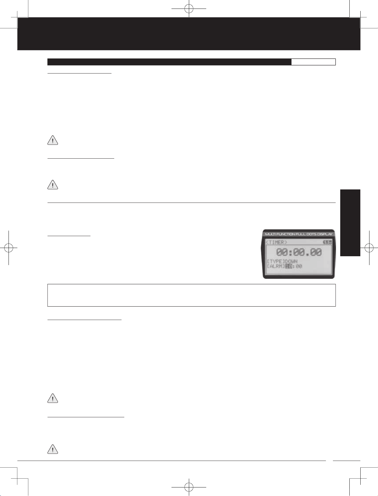
DOWN (Countdown Timer
)
The Countdown Timer function can be used to notify you of your model’s running time. For example, you can set the
Countdown Timer to alert you when it's time to refuel. When the Countdown Timer expires, a long audible tone will sound and
the Count Up Timer function begins automatically. This allows you to check the time elapsed since the Countdown Timer ran out.
Setting the Alarm:
1) From within the TIMER menu, scroll DOWN to highlight [ALRM] 05.
PROGRAM
2) Press the ENTER key, then scroll UP or DOWN to set the desired Alarm Minutes value.
3) To set the Alarm Seconds value, press the ENTER key, then scroll DOWN to highlight 00.
Press the ENTER key a second time, then scroll UP and DOWN to set the desired Alarm
Seconds value.
TIMER ALRM setting range is 00:00 to 99:59. The default setting is 5:00 minutes. An audible tone will sound in 1 second intervals
5 seconds before reaching the Countdown Alarm Time. When the Countdown Alarm Time is reached, a long audible tone
will sound.
Starting the Countdown Timer:
1) In the default configuration, Push-Button Switch Sw2 controls the Countdown Timer. Press and HOLD the Push-Button
Switch for 3 seconds. An audible double-tone will sound and DWN will flash on the Top Screen indicating the Countdown
Timer is in Stand-by.
To start the Countdown Timer, press the Push-Button Switch a second time or pull the Throttle Trigger. An audible
double-tone will sound and the Countdown Timer will start counting down. An audible tone will sound in 1 second intervals
5 seconds before reaching zero. When zero is reached, a long audible tone will sound and the Countdown Timer will begin
counting Up.
You can manually stop the Countdown Timer at any time by pressing the Push-Button Switch. Press the Push-Button Switch
again will start the Countdown Timer from where it was stopped.
If desired, the Timer Function can be assigned to Push-Button Switch Sw1. For more information, see the Key Assignments
section on pages 53 through 58.
Stopping the Countdown Timer:
1) To stop the Countdown Timer, press and HOLD the Push-Button Switch for 3 seconds. An audible double-tone will sound
indicating the Countdown Timer is stopped and either the remaining Countdown Time or elapsed Count Up Time will be
displayed on the Top Screen and in the TIMER menu.
The remaining Countdown Time or Count Up Time cannot be manually cleared. It will be automatically cleared when the
Countdown Timer is put in Stand-by again.
45
MT-4S User's Guide.indd 45 2015/10/27 14:39:05
90478 2.4GHZ FH4T RADIO SYSTEM USER'S GUIDE
TR
13.LAP (LAP TIMES
)
PROGRAM
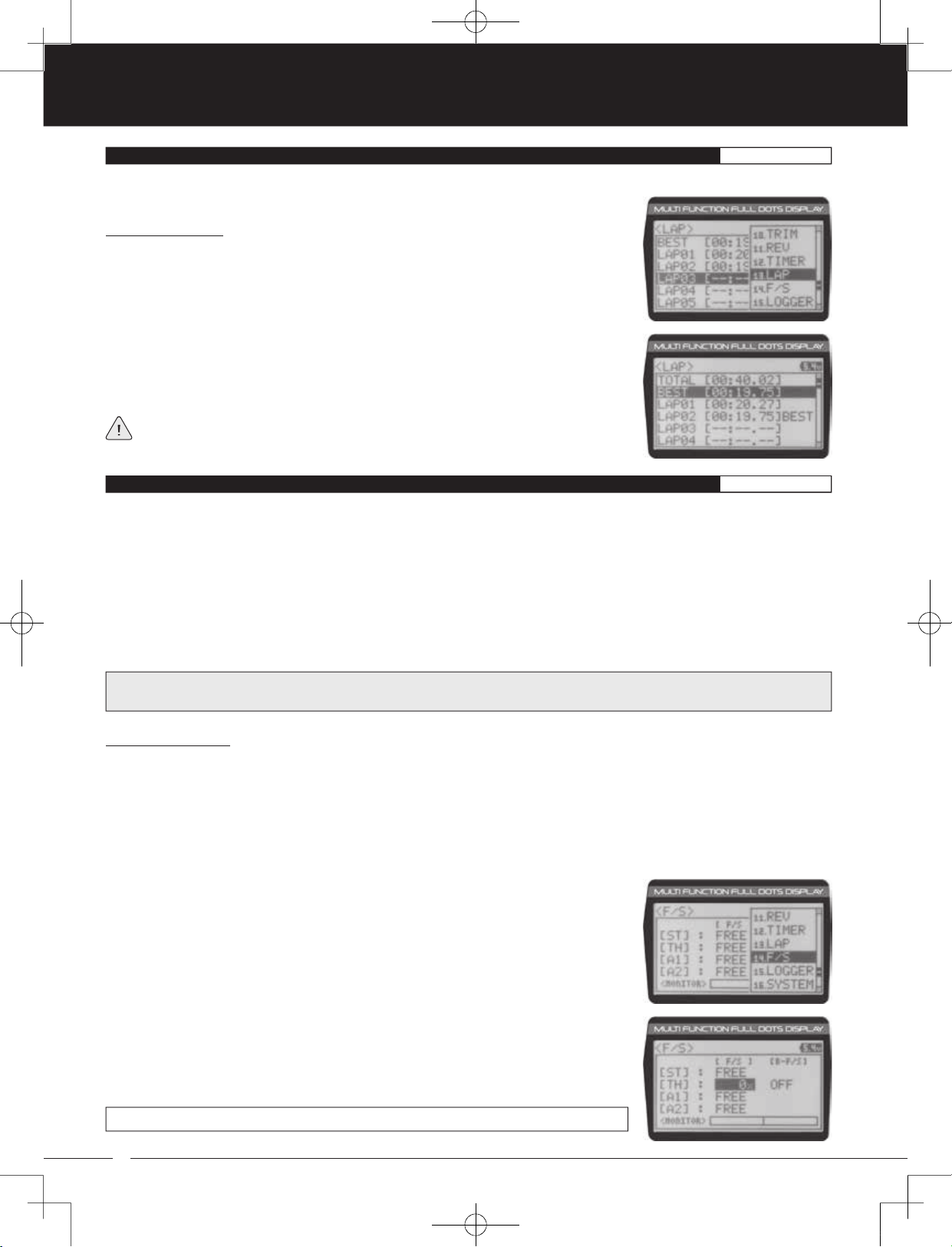
The Lap Times menu displays a total of up to 99 laps that are recorded using the Lap Timer function. Each Lap Time is displayed
along with the Best Lap Time and the Total (Cumulative) Lap Time.
Viewing Lap Times:
1) From the Top Screen, press the ENTER key to open the Programming Menu list.
2) Scroll UP or DOWN to highlight the LAP menu, then press the ENTER key. The LAP menu
will be displayed and the last Lap selected will be highlighted.
3) Scroll UP and DOWN to view the stored Lap Times. Lap Times are stored from the time
you start the Lap Timer to the time you Stop the Lap Timer. The Total (Cumulative) Lap
Time and your Best Lap Time are always displayed at the top of the list.
Lap Times are stored until you restart the Lap Timer function. When the Lap Timer
function is restarted, old Lap Times are cleared and new Lap Times are stored.
14.F /S (FAIL SAFE
)
PROGRAM
The Fail Safe function automatically moves the servos to a predetermined position in the event that the signal between the
transmitter and the receiver is interrupted, whether due to signal degradation or to low transmitter battery. Several different
setting options are available. The Fail Safe function can be set to Hold the servos in the last position they were in when the
signal was lost, or each of the servos can be set to move to a custom position when the signal is lost. For example, the throttle
servo moves to the Brake Side to engage the brakes and stop your model. If you're driving a gas- or glow-powered boat, the
Fail Safe function could be set to lower the throttle to idle and turn the rudder slightly left or right so that the boat will continue
in slow circles.
In addition, a Receiver Battery Voltage Fail Safe function is available which allows you to set a custom voltage that the Receiver
Battery Fail Safe function will Activate at. This is useful if you're using servos with a higher than normal current draw that might
run out of power before the receiver does.
IMPORTANT: The Fail Safe function will NOT OPERATE if the receiver loses power. It will operate only if the transmitter and
receiver signal is interrupted or if the transmitter loses power.
Setting the Fail Safe:
Fail Safe settings can be programmed for each of the four channels individually. In addition, Fail Safe settings are
model-specific, meaning you can have different Fail Safe settings for each Model in memory. Three Fail Safe options
are available for each channel as described below:
FREE - Fail Safe is disabled for this channel. Servos can move freely when the signal is lost.
HOLD - When Fail Safe Activates, the servo will be held in the last position it was in when the signal was lost.
% (PERCENTAGE) - When Fail Safe Activates, the servo will travel to the programmed position when the signal is lost.
1) From the Top Screen, press the ENTER key to open the Programming Menu list.
2) Scroll UP or DOWN to highlight the F/S menu, then press the ENTER key. The F/S menu
will be displayed and [ST]:FREE will be highlighted.
3) Scroll UP or DOWN to highlight the desired channel you would like to change the Fail
Safe option for.
4) Press the ENTER key, then scroll UP or DOWN to choose the desired Fail Safe option for
that channel. If you choose to program a % value, see step 5 below.
F/S setting range is FREE, HOLD, or %. The default setting is FREE.
46
MT-4S User's Guide.indd 46 2015/10/27 14:39:06
TR
90478 2.4GHZ FH4T RADIO SYSTEM USER'S GUIDE
14.F /S (FAIL SAFE
)
PROGRAM
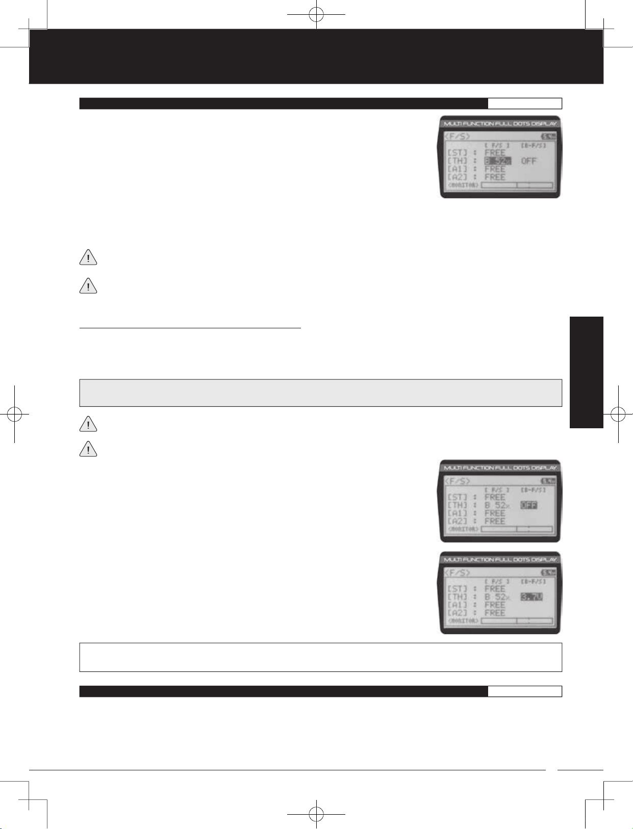
5) To program a Fail Safe percentage value, move the control the amount you want the
servo to move to when the Fail Safe function Activates and HOLD it in that position,
then press and HOLD the ENTER key until an audible tone sounds. The percentage and
direction the servo will travel will be displayed. For example, to set the Throttle Brake to
engage when the Fail Safe function Activates, push the throttle trigger toward the Brake
side the desired amount, HOLD the throttle trigger in that position, then press and HOLD
the ENTER key. The percentage value programmed will be indicated by two hash marks
on the Servo Monitor.
6) Check to ensure your Fail Safe settings are working properly. Make sure that both the transmitter and receiver are turned
ON, then, while someone is holding your model, turn the transmitter OFF. The servos should react correctly based on the
Fail Safe values chosen.
The Fail Safe settings will be retained even if the transmitter loses power or if the transmitter and receiver must be
paired again.
When using an FH2 receiver with your transmitter, these Fail Safe features are not supported. In this case, the Fail Safe
function must be programmed directly through the receiver. For more information, follow the Fail Safe Programming
instructions provided with your FH2 receiver.
Setting the Receiver Battery Voltage Fail Safe Function:
The Receiver Battery Voltage Fail Safe function is designed to alert you when your receiver battery requires recharging. This
ensures that the receiver battery's voltage doesn't drop so low that your servos aren't provided adequate voltage to operate
optimally. When Activated, the throttle servo will move to the predetermined position you programmed in step 5 in the Setting the
Fail Safe section above. If this occurs, recharge or replace your receiver batteries.
WARNING: This function is designed for use with glow- or gas-powered Models that use a separate receiver battery pack.
Do NOT use this function with an electric Model that uses the motor battery to power the servos and receiver.
PROGRAM
If FREE or HOLD is chosen for the Throttle channel, you cannot Activate the Receiver Battery Voltage Fail Safe function.
A % value must be chosen for the Throttle channel to be able to program and use the Receiver Battery Fail Safe function.
The Receiver Battery Voltage Fail Safe function works only with FH3 and FH4T receivers.
1) Follow steps 1 through 5 in the Setting the Fail Safe section to program a Throttle Fail
Safe percentage value.
2) From within the F/S menu, press the ENTER key, then scroll DOWN to highlight
[B-F/S] OFF.
3) Press the ENTER key, then scroll UP or DOWN to choose the desired Receiver Battery
Fail Safe Voltage value. Many factors, such as the current draw of your servos and how
many servos you're using, etc., will determine the value to use. A good starting point
would be 3.7V. If it appears your servos are slow or not producing adequate torque what
that Voltage value is reached, Increase the Voltage value.
F/S B-F/S setting range for FH4T receivers is OFF and 3.5V to 7.4V. F/S B-F/S setting range for FH3 receivers is OFF and
3.5V to 5.0V. The default setting is OFF regardless of the Modulation Type chosen.
15.LOGGER (TELEMETRY LOG
)
PROGRAM
The Telemetry Log function allows you to view a log of the Telemetry Data that is sent from the receiver to the transmitter. You
are able to view Telemetry Data for both Temperature outputs, the RPM output and the receiver's Voltage. This information can
be used to track specific information about your model, such as cylinder head temperature if you're running a nitro-powered
model or battery temperature if you're running an electric model and much more. The interval that Telemetry Data is read and
stored can be adjusted so that Telemetry Data can be stored for up to 90 minutes of use. The Telemetry Log can store 120
different data entries at intervals ranging from 00.1 seconds to 45.9 seconds.
47
MT-4S User's Guide.indd 47 2015/10/27 14:39:06

90478 2.4GHZ FH4T RADIO SYSTEM USER'S GUIDE
TR
15.LOGGER (TELEMETRY LOG
)
PROGRAM
IMPORTANT: Full telemetry support requires the use of an Airtronics 2.4GHz FH4T telemetry-capable surface receiver, such
as the RX-461 or RX-462, along with Airtronics Temperature and RPM Sensors (available separately). The included RX-472
receiver can send Telemetry Data for the voltage of the receiver battery pack only, unless used with the Airtronics Super
Vortex ZERO ESC (available separately) plugged into the BATT/SSL port of the included RX-472 receiver.
For information about using an optional Telemetry receiver with your 90478 transmitter and installing Telemetry Sensors
into your model, see the Telemetry Connections and Mounting section on pages 69 and 70. In addition, to be able to read
and log Telemetry Data, the Telemetry system must be turned ON. For more information about turning the Telemetry system
ON, see the Telemetry Setting section on pages 67 and 68.
Starting and Stopping the Telemetry Log:
The Telemetry Log function must be Started in order for the transmitter to read and store Telemetry Data from the receiver.
1) In the default configuration, Push-Button Switch Sw1 controls the Telemetry Log. To start the Telemetry Log, press the
Push-Button switch. LED1 (Blue) will flash, indicating the Telemetry Log is storing data. Telemetry Data is stored for all four
Telemetry functions, whether the Telemetry Sensors are hooked up or not.
2) To stop the Telemetry Log, press the Push-Button Switch a second time. If desired, the Telemetry Log Function can be
assigned to Push-Button Switch Sw2. For more information, see the Key Assignments section on pages 53 through 58.
Each time the Telemetry Log is started, any old Telemetry Data is automatically erased. In addition, the Telemetry Log will
stop automatically once the Telemetry Log is filled. The Telemetry Log can store 120 separate entries. If the Log Interval
is set to 00.1 seconds, the Telemetry Log can record for 12 seconds. If the Log Interval is set to 45.1 seconds, the Telemetry Log
can record for 90 minutes. To change the Log Interval value, see the Changing the Telemetry Log Step Value section on page 68.
Viewing Telemetry Data:
1) From the Top Screen, press the ENTER key to open the Programming Menu list.
2) Scroll UP or DOWN to highlight the LOGGER menu, then press the ENTER key. The
LOGGER menu will be displayed and TEMP1 DATA will be highlighted.
3) From within the LOGGER menu, scroll UP or DOWN to highlight the desired Telemetry
Data you would like to view. Choose from TEMP1 DATA, TEMP2 DATA, VOLT DATA or
RPM DATA.
4) Press the ENTER key to open the Telemetry Log.
5) To view the Telemetry Data at a specific point along the graph, scroll UP or DOWN to
move the vertical line right or left. The Telemetry Data for each point the vertical line is at
is displayed at the bottom of the screen.
6) To view all of the Telemetry Data points, press the ENTER key to open the Telemetry
Data List, then scroll DOWN to view all of the recorded Telemetry Data entries.
The Telemetry Log can be started and stopped while viewing Telemetry Data. To start the Telemetry Log, press and HOLD
the ENTER key and to stop the Telemetry Log, press and HOLD the ENTER key a second time.
48
MT-4S User's Guide.indd 48 2015/10/27 14:39:07
TR
90478 2.4GHZ FH4T RADIO SYSTEM USER'S GUIDE
SYSTEM MENUS OVERVIEW
SYSTEM
The different System Menus allow you to program options related directly to the use and
setup of the 90478 transmitter. From changing the Modulation Type, to adjusting LCD
properties and changing Key Assignments to suit your specific setup, it's all here.
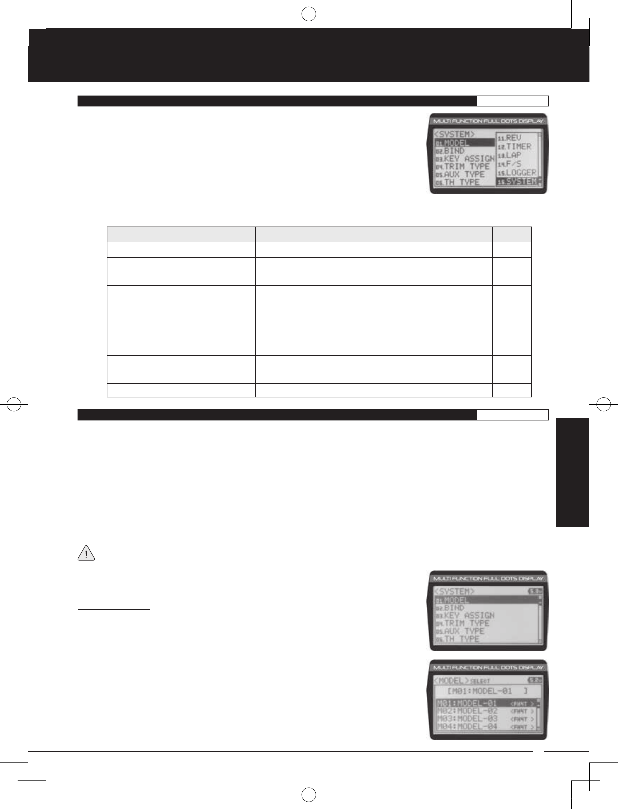
1) To access the various System Menus, turn the transmitter ON, then press the ENTER key
(Push-Button Rotary Dial) to open the Programming Menu list. Scroll DOWN to SYSTEM,
then press the ENTER key a second time to open the System Menu. A list of System
Menus will be displayed and the first System Menu will be highlighted.
2) Use the Push-Button Rotary Dial to scroll UP or DOWN to highlight the desired System Menu, then press the ENTER key to
open the highlighted System Menu.
MENU MENU NAME MENU DESCRIPTION
01.MODEL
02.BIND
03.KEY ASSIGN
04.TRIM TYPE
05.AUX TYPE
06.TH TYPE
07.BUZZER
08.BATTERY
09.LCD
SYSTEM MENUS
10.TELEMETRY
11.VR ADJUST
Model
Binding
Key Assignments
Servo Trim Type
Auxiliary Type
Throttle Type
Audible Key Tone
Voltage Alarm
Contrast
Telemetry
Variable Rate Adjust
Model Select, Model Naming, Model Copy and Model Clear
Bind, Select Modulation Type and Servo Operating Mode
Assign Functions to the Switches, Rotary Dial and Auxiliary Lever
Change the Servo Trim Type
Choose Auxiliary 1 and Auxiliary 2 Programming Functions
Change the Throttle Servo Travel Proportion
Adjust Audible Key Tone Volume and Tone
Specify Transmitter Battery Low Voltage and Limit Alarms
Adjust LCD Contrast and Backlight Options
Program Telemetry Display Options
Calibrate Steering, Throttle and Auxiliary Lever Controls
PAGE
PG. 49
PG. 52
PG. 53
PG. 59
PG. 59
PG. 60
PG. 61
PG. 61
PG. 62
PG. 63
PG. 68
01.MODEL (MODEL SELECT, NAMING, COPY AND CLEAR
)
SYSTEM
The Model menu allows you to select different models using the Model Select function, name your saved models using the
Model Naming function, and copy Programming Data from one model to another, or clear Programming Data from one or
more models using the Model Copy and Model Clear functions. Programming Data for up to 18 different models can be stored
in the transmitter's memory. This allows you to use the transmitter with different models and quickly and easily select the
Programming Data for each of them. In addition, a Model Select Shortcut function is also featured for quick access to the Model
Select (Direct Model) function.
MODEL SELECT (Model Select
)
The Model Select function allows you to load the Programming Data for the particular model you wish to drive. The Model Select
menu displays the currently selected model, along with a list of available models that can be selected. The Modulation Type for
each model is also displayed. The transmitter can store Programming Data for up to 18 different models.
When a model is selected and loaded, the Programming Data for that model will be loaded immediately. Modulation
Type, Servo Operating Mode, Key Assignments, Trim Type, Auxiliary Type and Throttle Type options, in addition to all
Programming Menu function options are model-specific.
Selecting a Model:
1) From within the SYSTEM menu, scroll UP or DOWN to highlight the MODEL menu.
2) Press the ENTER key to open the MODEL menu. MODEL SELECT will be highlighted.
SYSTEM
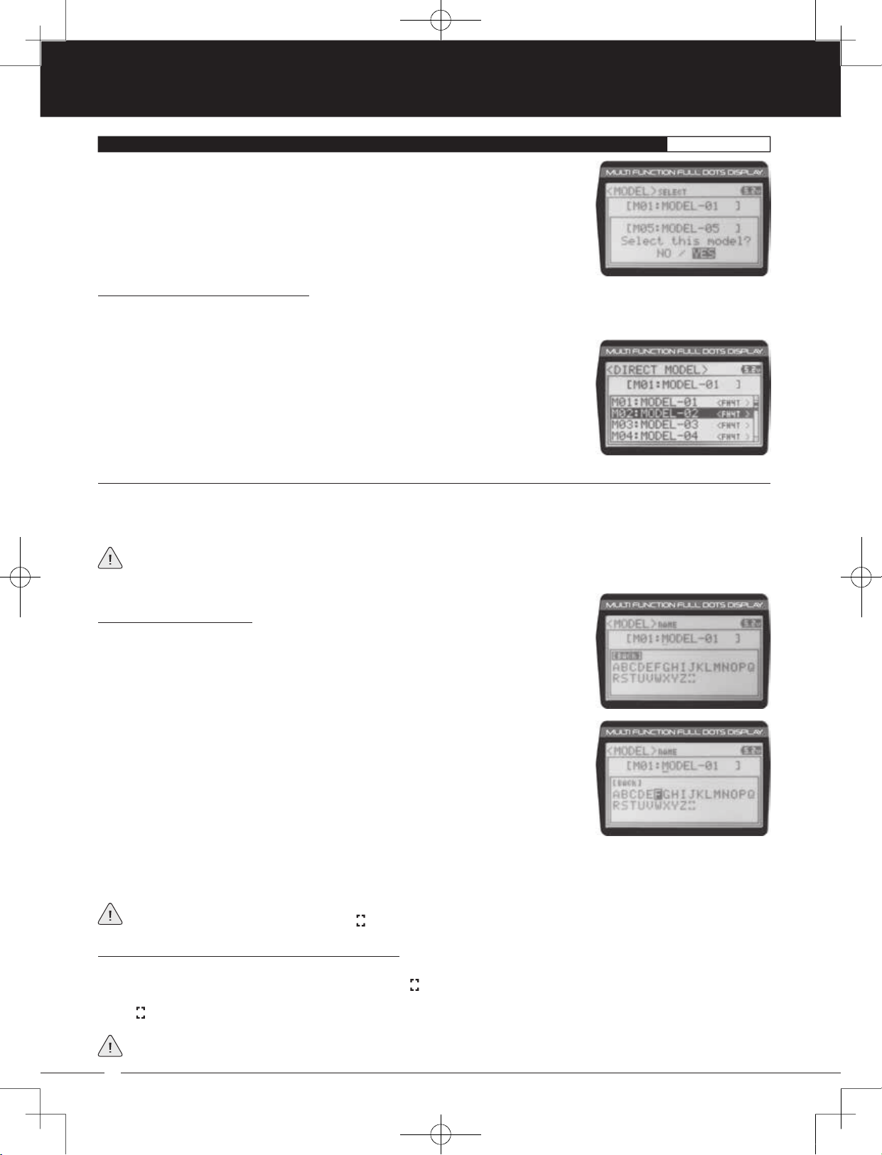
3) Press the ENTER key. The MODEL SELECT menu will be displayed and the currently
selected model in the Model Select List will be highlighted.
49
MT-4S User's Guide.indd 49 2015/10/27 14:39:07
90478 2.4GHZ FH4T RADIO SYSTEM USER'S GUIDE
TR
01.MODEL (MODEL SELECT, NAMING, COPY AND CLEAR
)
SYSTEM
4) Scroll UP or DOWN to highlight the model you would like to select, then press the ENTER
key. Select this model? NO/YES will be displayed.
5) Scroll DOWN to highlight YES, then press the ENTER key. The model that you just
selected will be displayed above the Model Select List and that model's Programming
Data will be loaded.
Model Select Shortcut (Direct Model):
The Model Select Shortcut function allows you to jump directly to the DIRECT MODEL menu when you turn the transmitter ON.
This menu works the same as the MODEL SELECT menu and makes it much quicker select your desired model.
1) Turn the transmitter OFF.
2) Press and HOLD the BACK/CANCEL key, then turn the transmitter ON. The DIRECT
MODEL menu will be displayed. To select a model, follow steps 4 and 5 in the Selecting
a Model section above.
MODEL NAME (Model Naming
)
The Model Naming function allows you to name each of the 18 individual models. This makes it easy to keep track of multiple
models. The Model Name can consist of up to 10 letters, numbers, or symbols. Choose from capital letters, lower case letters,
numbers, and various symbols.
A model must be selected before a Model Name can be entered or modified. In the default configuration, M01:MODEL-1
is selected. To enter a Model Name for another model, that model must first be selected using the Model Select function
or the Model Select Shortcut function. For more information, see the Model Select section on pages 49 and 50.
Changing the Model Name:
1) From within the MODEL menu, scroll DOWN to highlight MODEL NAME.
2) Press the ENTER key. The MODEL NAME menu will be displayed, [BACK] will be
highlighted and the underscore will be flashing under the first editable character in the
Model Name.
3) Scroll UP or DOWN to move the underscore to the character you would like change.
4) Press the ENTER key, then scroll UP or DOWN to highlight a character in the Character
List. Press the ENTER key a second time to select the highlighted character. That
character will be displayed and the underscore will move to the next space in the Model
Name.
5) Repeat steps 3 and 4 to enter the rest of the characters. Up to ten characters can be entered. Press the BACK/CANCEL key
to re-gain control of the underscore (the underscore will flash indicating you can scroll UP or DOWN to move it Forward or
Backward).
To select lower case letters, numbers or symbols, continue to scroll UP or DOWN through the various Character Lists. To
add a space in your Model Name, use the
icon.
Deleting a Single Character or an Entire Model Name:
1) Scroll UP or DOWN to move the underscore under the character in the Model Name you want to delete. Press the ENTER
key, then scroll UP or DOWN to highlight [BACK] or the
icon in the Character List and press the ENTER key. If you want to
delete the entire name, move the underscore to the last character in the name, scroll UP or DOWN to highlight [BACK] or
the
icon in the Character List, then repeatedly press the ENTER key.
If you can't move the underscore, press the BACK/CANCEL key to re-gain control of the underscore (the underscore will
flash indicating you can scroll UP or DOWN to move it Forward or Back).
50
MT-4S User's Guide.indd 50 2015/10/27 14:39:08

TR
90478 2.4GHZ FH4T RADIO SYSTEM USER'S GUIDE
01.MODEL (MODEL SELECT, NAMING, COPY AND CLEAR
MODEL COPY (Model Programming Data Copy
)
)
SYSTEM
The Model Copy function allows you to copy the Programming Data from one model to another model. For example, if you have
two models that are similar, you can copy the Programming Data from the first model to the second model to use as a base to
start fine-tuning the programming for the second model.
The Model Copy function allows you to copy Programming Data FROM the currently selected model TO any other model
in the Model Copy List. Make sure that prior to using the Model Copy function, you first select and load the desired Model
Programming Data you want to copy FROM, using the Model Select function.
Copying Model Programming Data:
1) From within the MODEL menu, scroll DOWN to highlight MODEL COPY.
2) Press the ENTER key. The MODEL COPY menu will be displayed and the first model in
the Model Copy List will be highlighted.
The currently selected model is displayed above the Model Copy List.
3) Scroll UP or DOWN to highlight the model you would like to copy the Programming
Data TO.
4) Press the ENTER key. Copy to this model? NO/YES will be displayed.
5) Scroll DOWN to highlight YES, then press the ENTER key. After ~3 seconds, Executed
will flash, indicating the Programming Data has been copied to the highlighted model.
All model-specific Programming Data, including the Model Name will be copied to the highlighted model. If you want to
go back and change models or you don't want to copy the Programming Data for any reason, press the BACK/CANCEL key.
MODEL CLEAR (Model Programming Data Reset
)
The Model Clear function allows you to Reset model-specific Programming Data for any model back to the factory default
settings.
WARNING: When the Model Clear function is Executed, all custom Programming Data for that model will be lost!
Clearing Model Programming Data:
1) Using the Model Select function, select the model you would like to Reset the Programming Data for.
2) From within the MODEL menu, scroll DOWN to highlight MODEL CLEAR.
3) Press the ENTER key. Clear this model? NO/YES will be displayed.
The currently selected model is displayed at the top of the MODEL CLEAR menu.
4) Scroll DOWN to highlight YES, then press the ENTER key. After ~3 seconds, Executed will flash, indicating the Programming
Data has been Reset to the default values.
SYSTEM
If you want to go back and change models or you don't want to Reset the Programming Data for any reason, press the
BACK/CANCEL key. When Executed, all model-specific Programming Data, including the Model Name, Modulation Type,
Servo Operating Mode, Key Assignments, Trim Type, Auxiliary Type and Throttle Type options will be Reset to the default values.
51
MT-4S User's Guide.indd 51 2015/10/27 14:39:08
90478 2.4GHZ FH4T RADIO SYSTEM USER'S GUIDE
TR
02.BIND (BINDING, MODULATION TYPE AND SERVO OPERATING MODE
)
SYSTEM
The Binding function allows you to Bind the transmitter and receiver pair. When new, it is necessary to pair the transmitter
and receiver to prevent interference from transmitters operated by other users. This operation is referred to as Binding. Once
the Binding process is complete, the setting is remembered even when the transmitter and receiver are turned OFF. Therefore,
this procedure usually only needs to be done once. In addition, the Modulation Type and Servo Operating Mode can also be
changed to suit your specific setup.
Changing the Modulation Type:
The Modulation Type function allows you to choose the transmitter Modulation Type. The Modulation Type can be changed
to match the receiver you're using. For example, if you wish to use an Airtronics 2.4GHz FH2 receiver with your transmitter,
you would need to change the Modulation Type to FH2 prior to Binding your transmitter and receiver. Modulation Type
is model-specific, meaning that you can have one model use FH4T Modulation and another model use FH2 Modulation, etc.
The Modulation Type must be chosen prior to Binding the transmitter and receiver. Make sure the Modulation Type you
choose matches the Modulation Type of the receiver you're using.
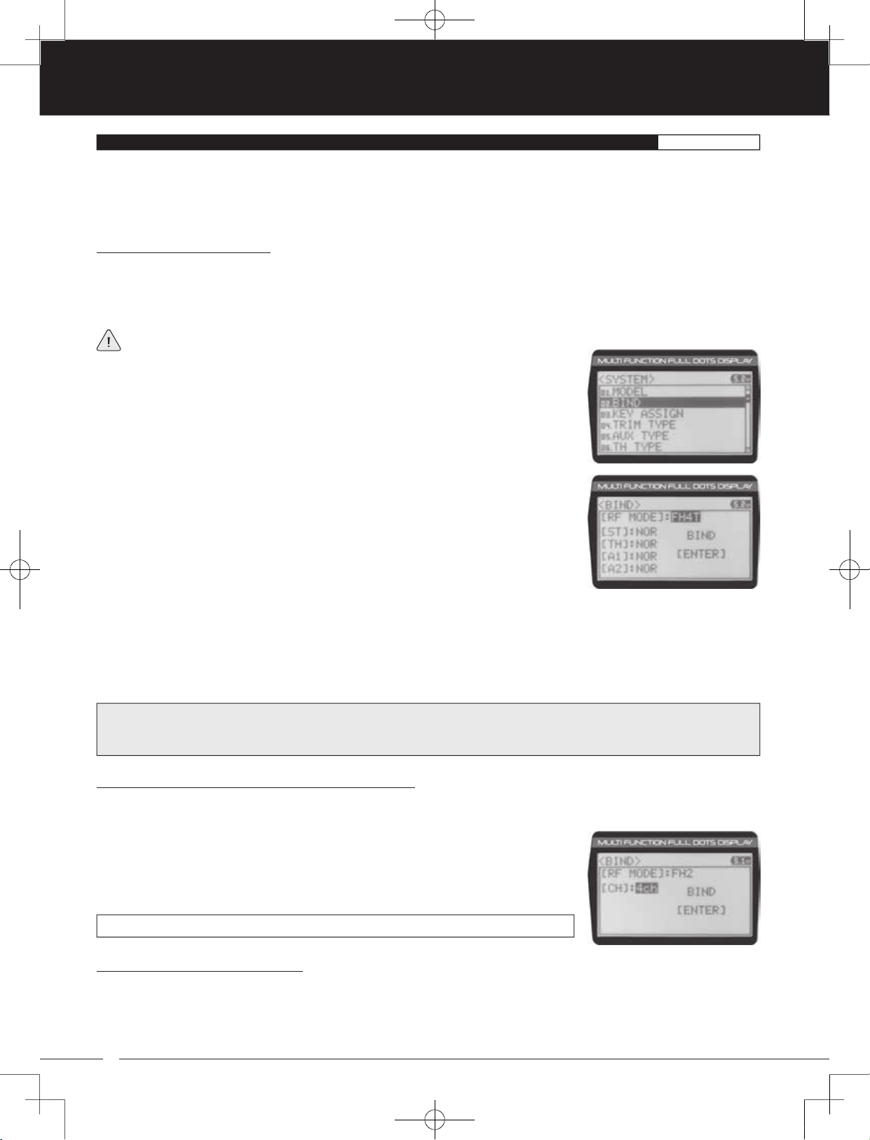
1) From within the SYSTEM menu, scroll UP or DOWN to highlight the BIND menu.
2) Press the ENTER key. The BIND menu will be displayed and [RF MODE]:FH4T will be
highlighted.
3) Press the ENTER key, then scroll UP or DOWN to select the desired Modulation Type,
then press the ENTER key a second time. Set to (Modulation Type) NO/YES will be
displayed.
4) Scroll DOWN to highlight YES, then press the ENTER key.
The following Modulation Type options are available:
FH2 - Select this Modulation Type when using an Airtronics 2.4GHz FH2 surface receiver.
FH3 - Select this Modulation Type when using an Airtronics 2.4GHz FH3 receiver.
FH4T - Select this Modulation Type when using an Airtronics 2.4GHz FH4T Telemetry receiver.
FH3F/FH4FT - These Modulation Types are NOT used in North America. They are typically used in France.
IMPORTANT: Not all BIND menu functions are supported by all Modulation Types. Only supported functions will be
displayed once a Modulation Type is chosen. For example, the FH2 Modulation Type does not support the ability to change
the Servo Operating Mode.
Changing the Channel Mode - FH2 Modulation Type Only:
When the FH2 Modulation Tyep is selected, you can choose to operate the transmitter in either 2-Channel Mode or 4-Channel
Mode. This option is available ONLY when [RF MODE] FH2 is selected.
1) From within the BIND menu, scroll DOWN to highlight [CH]:4ch.
2) Press the ENTER key, then scroll UP or DOWN to choose the desired Channel Mode.
Selecting 2CH will enable 2-channel operation (Steering and Throttle). Selecting 4CH
will enable 4-channel operation (Steering, Throttle, Auxiliary 1 and Auxiliary 2).
BIND CH setting range is 2CH and 4CH. The default setting is 4CH.
Changing the Servo Operating Mode:
The Servo Operating Mode function is used to optimize the radio control system to suit the type of servos you're using in your
model. For example, using the SHR setting with Digital servos will Increase the servo's response time, even above the
manufacturer's stated specification. If you're using Airtronics SRG Digital servos, you can use the SSR setting for the fastest
response time. The combination of using Digital servos and using the correct Servo Operating Mode results in the ultimate feel
and response, making you feel more in control of your model than ever.
52
MT-4S User's Guide.indd 52 2015/10/27 14:39:09
TR
90478 2.4GHZ FH4T RADIO SYSTEM USER'S GUIDE
02.BIND (BINDING, MODULATION TYPE AND SERVO OPERATING MODE
)
SYSTEM
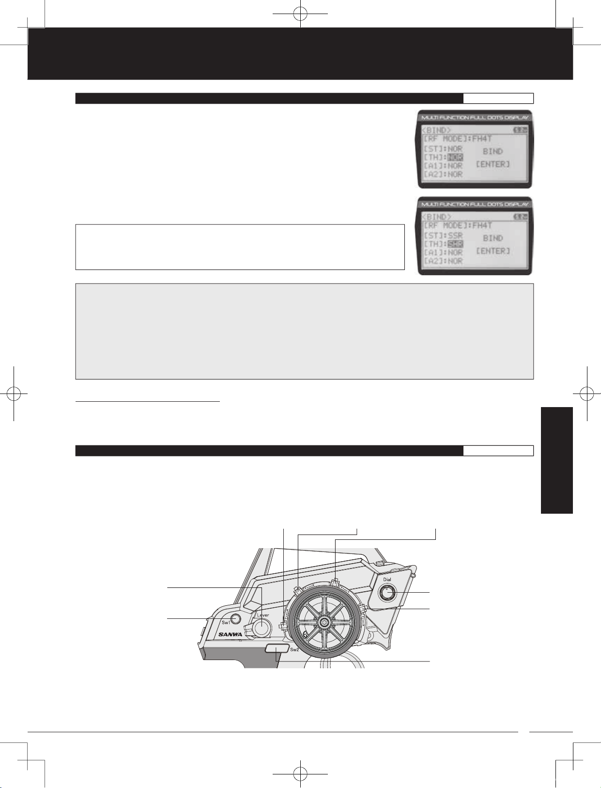
1) From within the BIND menu, scroll UP or DOWN to highlight the desired channel you
would like to change the Servo Operating Mode for. Choose from either [ST]:NOR
(Steering), [TH]:NOR (Throttle), [A1]:NOR (Auxiliary 1) or [A2]:NOR (Auxiliary 2).
2) Press the ENTER key, then scroll UP or DOWN to choose the desired Servo Operating
Mode option for that channel.
SERVO OPERATING MODE setting range is NOR, SHR and SSR. The default setting is
NOR. SSR Operating Mode is not supported when the FH3 or FH3F Modulation Type
is selected. No Servo Operating Modes are supported when the FH2 Modulation Type
is selected.
IMPORTANT INFORMATION ABOUT SERVO OPERATING MODES:
If you're using Analog servos in your model, DO NOT use SHR or SSR Servo Operating Mode for those channels. Use the
NOR (Normal) Servo Operating Mode with Analog servos. Using SHR or SSR Servo Operating Mode with Analog servos can
result in poor performance or even damage to the servos or the receiver! In some cases, the servo may not operate at all.
Not all ESCs are compatible with SHR or SSR Servo Operating Modes. If your ESC does not operate correctly, change the
Servo Operating Mode to NOR (Normal) for that channel (or channels).
SHR and SSR Servo Operating Modes should only be used with Digital servos. While the SHR Servo Operating Mode can be
used with any brand of Digital servo, the SSR Servo Operating Mode should ONLY be used with Airtronics SRG Digital servos.
Binding the Transmitter and Receiver:
To Bind the transmitter and receiver, please see the Transmitter and Receiver Binding section on page 16. Prior to Binding the
transmitter and receiver, make sure to choose the desired Modulation Type that matches the receiver you're using. Servo
Operating Mode can be changed prior to Binding the transmitter and receiver, or after the Binding process.
03.KEY ASSIGN (KEY ASSIGNMENTS
)
SYSTEM
The Key Assignments function allows you to assign different functions to each of the two Push-Button Switches, the four Trim
Switches, the Dial Knob and the Auxiliary Lever. In addition, the ON/OFF behavior of some Push-Button Switch functions can
be changed. The Key Assignments function also allows you to change the Direction of Travel and the Trim Resolution of the
four Trim Switches and the Rotary Dial. This allows you to fine-tune the movement of the servos when the Trim Switches are
pressed and the Rotary Dial is turned.
Auxiliary Lever
Push-Button
Trim Switch
(Trm4)
Trim Switch
(Trm1)
Trim Switch
(Trm2)
Dial Knob
Trim Switch (Trm3)
Switch (Sw1)
Push-Button
Switch (Sw2)
Trm1 - Steering Trim
Trm2 - Throttle Trim
Trm3 - Steering Dual Rate
Trm4 - Brake Dual Rate
Sw1 - Telemetry Logger ON/OFF
Sw2 - Timer ON/OFF
Dial Knob - Auxiliary 1 Channel 3
Auxiliary Lever - Auxiliary 2 Channel 4
53
SYSTEM
MT-4S User's Guide.indd 53 2015/10/27 14:39:10
90478 2.4GHZ FH4T RADIO SYSTEM USER'S GUIDE
TR
03.KEY ASSIGN (KEY ASSIGNMENTS
SWITCH (Push-Button Switch Key Assignments
)
)
SYSTEM
The Key Assignments function allows you to assign the ON/OFF control of various functions to Push-Button Switches Sw1 and
Sw2. This allows you to use the Push-Button Switches to turn functions OFF and ON during use. One function can be assigned
to each Push-Button switch, although both Push-Button Switches can be OFF or ON at the same time. In addition, the ON/OFF
behavior of some Push-Button Switch Key functions can be changed.
When you program a function, that function is ON (Active) by default, unless the function's default ON/OFF value is OFF
as noted in the table below. To toggle the function OFF and ON it must be assigned to a Push-Button Switch.
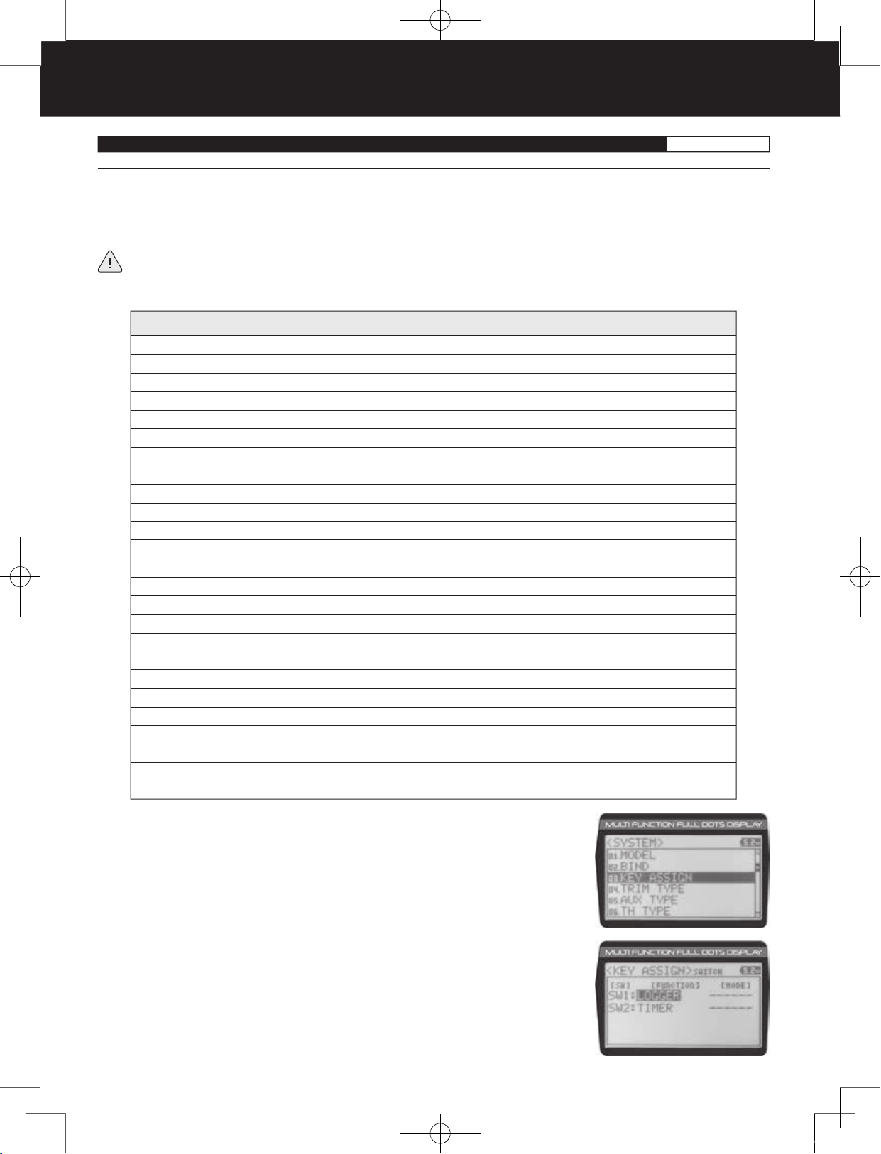
This table shows the different functions that can be programmed to the two Push-Button Switches:
MENU FUNCTION DEFAULT SWITCH
OFF
D/R-ST
D/R-TH
D/R-BR
CUR-ST
CUR-TH
SPD-ST
SPD-TH
ALB
OFFSET
AUX1
AUX2
A1CODE1
A1CODE2
A1CODE3
A1CODE4
A1CODE5
A2CODE1
A2CODE2
A2CODE3
A2CODE4
A2CODE5
TIMER
TE-CLR
LOGGER
Inhibited
Dual Rate-Steering
Dual Rate-Throttle
Dual Rate-Brake
Curve-Steering
Curve-Steering
Servo Speed-Steering
Servo Speed-Throttle
Anti-Lock Braking
Throttle Offset
Auxiliary 1 Channel 3
Auxiliary 2 Channel 4
Auxiliary 1 CODE1
Auxiliary 1 CODE2
Auxiliary 1 CODE3
Auxiliary 1 CODE4
Auxiliary 1 CODE5
Auxiliary 2 CODE1
Auxiliary 2 CODE2
Auxiliary 2 CODE3
Auxiliary 2 CODE4
Auxiliary 2 CODE5
Timers
Telemetry Clear
Telemetry Logger
Sw2
Sw1
DEFAULT MODE DEFAULT ON/OFF
------
Toggle
Toggle
Toggle
Toggle
Toggle
Toggle
Toggle
Toggle
Toggle
Toggle
Toggle
Toggle
Toggle
Toggle
Toggle
Toggle
Toggle
Toggle
Toggle
Toggle
Toggle
------
------
------
------
ON
ON
ON
ON
ON
ON
ON
ON
ON
ON
ON
ON
ON
ON
ON
ON
ON
ON
ON
ON
ON
OFF
OFF
OFF
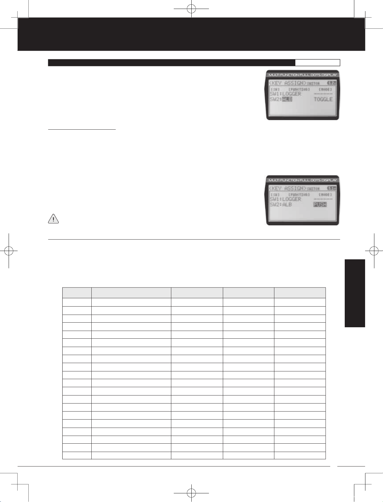
Changing the Push-Button Switch Function:
1) From within the SYSTEM menu, scroll UP or DOWN to highlight the KEY ASSIGN menu.
2) Press the ENTER key to open the KEY ASSIGN menu. SWITCH will be highlighted.
3) Press the ENTER key. The SWITCH menu will be displayed and SW1:LOGGER will be
highlighted.
54
MT-4S User's Guide.indd 54 2015/10/27 14:39:10
TR
90478 2.4GHZ FH4T RADIO SYSTEM USER'S GUIDE
03.KEY ASSIGN (KEY ASSIGNMENTS
)
SYSTEM
4) Scroll UP or DOWN to highlight the function you would like to change for either SW1
or SW2.
5) Press the ENTER key, then scroll UP or DOWN to choose the desired function for either
SW1 or SW2. A list of functions that can be assigned to the Push-Button Switches is
shown in the table on the previous page.
Changing the Switch Mode:
Some functions allow you to change how the Push-Button Switch operates. The following Switch Modes are available:
TOGGLE - When selected, press the Push-Button Switch to turn the function ON and press the Push-Button Switch a
second time to turn the function OFF. See note on previous page.
PUSH - When selected, press and HOLD the Push-Button Switch to turn the function ON. When the Push-Button Switch is
released, the function will be turned OFF.
1) From within the KEY ASSIGN SWITCH menu, scroll DOWN to highlight the MODE you
would like to change for either SW1 or SW2.
2) Press the ENTER key, then scroll UP or DOWN to choose the desired Switch Mode
setting, either TOGGLE or PUSH.
The Switch Mode cannot be changed for all functions. When [MODE] ------, the
Push-Button Switch will act as if it were in Toggle Mode.
TRIM, DIAL AND LEVER (Trim Switch, Rotary Dial and Auxiliary Lever Key Assignments
)
The Key Assignments function allows you to assign different functions to Trim Switches Trm1, Trm2, Trm3 and Trm4, the Rotary
Dial and the Auxiliary Lever. This allows you to use the Trim Switches, Rotary Dial and Auxiliary Lever to control those functions
while you're driving. In addition, the Direction of Travel (REV) and the Trim Resolution (Step value) of each Trim Switch and the
Rotary Dial can be changed. The High and Low Travel Limits and the Direction of Travel of the Auxiliary Lever can be changed, too.
This table shows the different functions that can be programmed to the Trim Switches, Rotary Dial and Auxiliary Lever. Table is
continued on the next page.
MENU FUNCTION DEFAULT SWITCH
OFF
TRIM-ST
TRIM-TH
TRIM-A1
TRIM-A2
D/R-ST
D/R-TH
D/R-BR
CU-R-ST
CU-P-ST
CU-R-TH
CU-P-TH
CU-R-BR
CU-P-BR
SP-ST-F
SP-ST-R
SP-TH-F
SP-TH-R
ALB-PO
ALB-ST
Inhibited
Trim-Steering
Trim-Throttle
Trim-Auxiliary 1
Trim-Auxiliary 2
Dual Rate-Steering
Dual Rate-Throttle
Dual Rate-Brake
Curve-Rate-Steering
Curve-Point-Steering
Curve-Rate-Throttle
Curve-Point-Throttle
Curve-Rate-Brake
Curve-Point-Brake
Speed-Steering-Forward
Speed-Steering-Return to Neutral
Speed-Throttle-Forward
Speed-Throttle-Return to Neutral
Anti-Lock Braking-Point
Anti-Lock Braking-Stroke
Trm1
Trm2
Trm3
Trm4
------
5
5
1
1
DEFAULT REVDEFAULT STEP
------
NOR
NOR
NOR
NOR
55
SYSTEM
MT-4S User's Guide.indd 55 2015/10/27 14:39:10
90478 2.4GHZ FH4T RADIO SYSTEM USER'S GUIDE
TR
03.KEY ASSIGN (KEY ASSIGNMENTS
MENU FUNCTION DEFAULT SWITCH
ALB-LG
ALB-HL
ALB-RE
OFFSET
AUX1
AUX2
A1CODE1
A1CODE2
A1CODE3
A1CODE4
A1CODE5
A2CODE1
A2CODE2
A2CODE3
A2CODE4
A2CODE5
INC/DEC
Anti-Lock Braking-Lag
Anti-Lock Braking-Hold
Anti-Lock Braking-Release
Throttle Offset
Auxiliary 1 Channel 3
Auxiliary 2 Channel 4
Auxiliary 1 CODE1
Auxiliary 1 CODE2
Auxiliary 1 CODE3
Auxiliary 1 CODE4
Auxiliary 1 CODE5
Auxiliary 2 CODE1
Auxiliary 2 CODE2
Auxiliary 2 CODE3
Auxiliary 2 CODE4
Auxiliary 2 CODE5
Increase/Decrease Values
)
SYSTEM
DEFAULT REVDEFAULT STEP
Rotary Dial
Auxiliary Lever
5
N/A
------
NOR
N/A
------
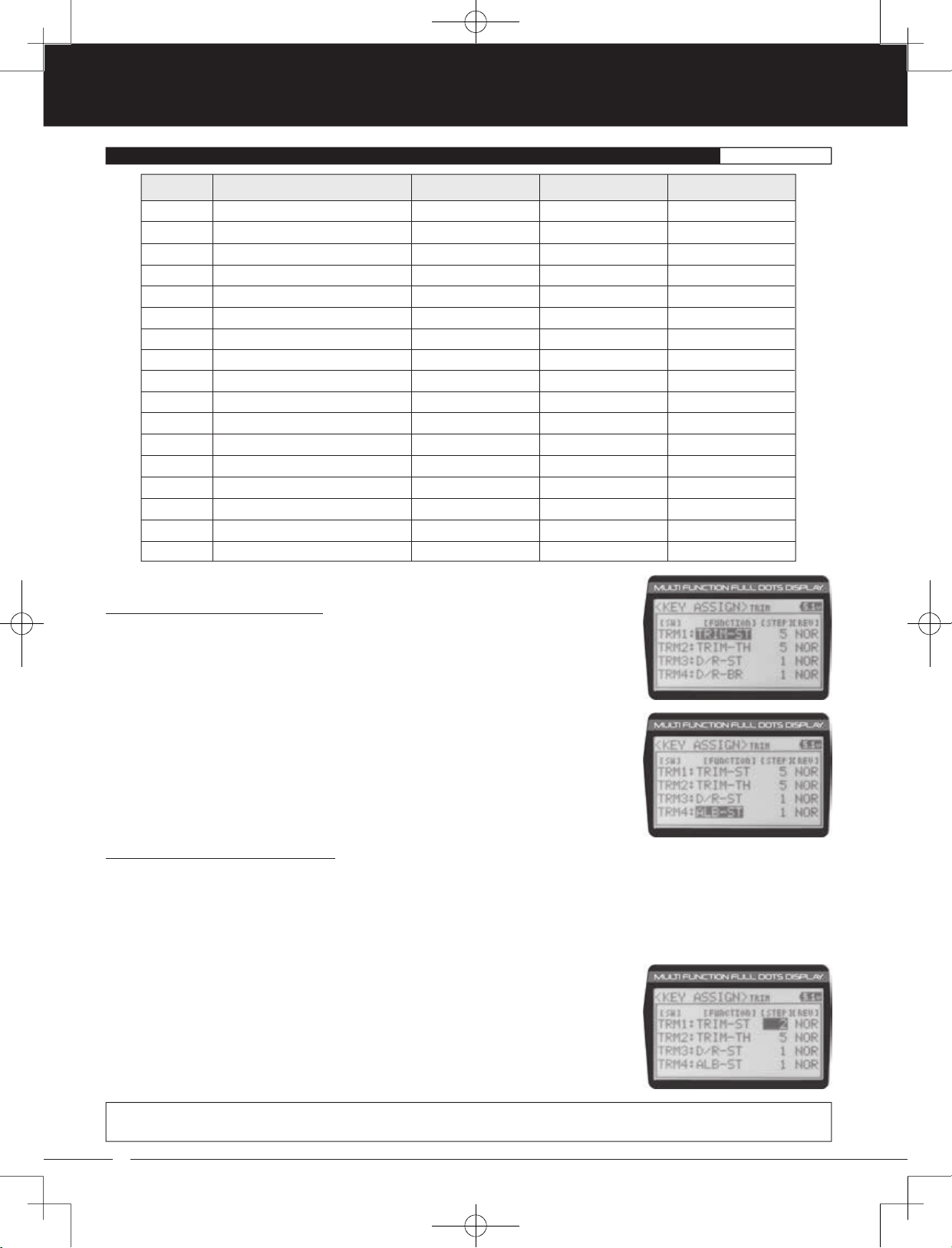
Changing the Trim Switch Function:
1) From within the KEY ASSIGN menu, scroll UP or DOWN to highlight TRIM.
2) Press the ENTER key. The TRIM menu will be displayed and TRM1:TRIM-ST will be
highlighted.
3) Scroll UP or DOWN to highlight the function you would like to change for either TRM1,
TRM2, TRM3 or TRM4.
4) Press the ENTER key, then scroll UP or DOWN to choose the desired function for Trim
Switch Trm1, Trm2, Trm3 or Trm4. A list of functions that can be assigned to the Trim
Switches is shown in the table above and on the previous page.
Changing the Trim Switch Step Value:
The Step function allows you to adjust how far the servos travel when the Trim Switches are pressed. You can increase the
Trim Resolution by decreasing the Step value, so that the servos travel less when you press the Trim Switches. This makes it
possible to fine-tune servo movement extremely accurately.
Alternately, you could decrease the Trim Resolution by increasing the Step values, so that the servos travel more when you
press the Trim Switches. This setting may not be as accurate, although it allows you to command large amounts of servo
travel at a time.
1) From within the TRIM menu, scroll UP or DOWN to highlight the Step value you would
like to change for either TRM1, TRM2, TRM3 or TRM4.
2) Press the ENTER key, then scroll UP or DOWN to choose the desired Step value for Trim
Switch Trm1, Trm2, Trm3 or Trm4.
TRIM STEP setting range is 1 to 100. The default setting for TRM1 is 5, for TRM2 is 5, for TRM3 is 1 and for TRM4 is 1. The Step
value is a percentage of servo travel.
56
MT-4S User's Guide.indd 56 2015/10/27 14:39:11

TR
90478 2.4GHZ FH4T RADIO SYSTEM USER'S GUIDE
03.KEY ASSIGN (KEY ASSIGNMENTS
)
SYSTEM
Changing the Trim Switch Direction of Travel:
The direction that the Trim Switches move the servos can be changed from Normal to Reverse. In Normal mode, the Trim
Switches will move the servos toward the High Side when the Trim Switches are pushed Forward. In Reverse mode, the
Trim Switches will move the servos toward the Low Side (the opposite direction) when the Trim Switches are pushed Forward.
1) From within the TRIM menu, scroll UP or DOWN to highlight the REV value you would
like to change for either TRM1, TRM2, TRM3 or TRM4.
2) Press the ENTER key, then scroll UP or DOWN to choose the desired REV value for Trim
Switch Trm1, Trm2, Trm3 or Trm4.
TRIM REV setting range is NOR and REV. The default setting for all Trim Switches is NOR.
Changing the Rotary Dial Function:
1) From within the KEY ASSIGN menu, scroll UP or DOWN to highlight DIAL.
2) Press the ENTER key. The DIAL menu will be displayed and FUNCTION AUX1 will be
highlighted.
3) Press the ENTER key, then scroll UP or DOWN to choose the desired function for the
Rotary Dial. A list of functions that can be assigned to the Rotary Dial is shown in the
table on pages 55 and 56.
Changing the Rotary Dial Step Value:
The Step function allows you to adjust how far the servo travels when the Rotary Dial is turned. You can increase the Dial
Resolution by decreasing the Step value, so that the servo travels less when you turn the Rotary Dial. This makes it possible to
fine-tune servo movement extremely accurately .
Alternately, you could decrease the Dial Resolution by increasing the Step value, so that the servo travels more when you turn
the Rotary Dial. This setting may not be as accurate, although it allows you to command large amounts of servo travel at
a time.
1) From within the DIAL menu, scroll UP or DOWN to highlight STEP 5.
2) Press the ENTER key, then scroll UP or DOWN to choose the desired Step value for the
Rotary Dial.
DIAL STEP setting range is 1 to 100. The default setting is 5. The Step value is a percentage
of servo travel.
Changing the Rotary Dial Direction of Travel:
The direction that the Rotary Dial moves the servo can be changed from Normal to Reverse. In Normal mode, the Rotary Dial
will move the servo toward the High Side when the Rotary Dial is turned clockwise. In Reverse mode, the Rotary Dial will move
the servo toward the Low Side (the opposite direction) when the Rotary Dial is turned clockwise.
1) From within the DIAL menu, scroll UP or DOWN to highlight REV NOR.
2) Press the ENTER key, then scroll UP or DOWN to choose the desired REV value for the
Rotary Dial.
SYSTEM
DIAL REV setting range is NOR and REV. The default setting is NOR.
57
MT-4S User's Guide.indd 57 2015/10/27 14:39:11

90478 2.4GHZ FH4T RADIO SYSTEM USER'S GUIDE
TR
03.KEY ASSIGN (KEY ASSIGNMENTS
)
SYSTEM
Changing the Auxiliary Lever Function:
In general, the Auxiliary Lever is used to control Auxiliary 1 Channel 3 or Auxiliary 2 Channel 4. Adjusting the High and Low
Tweak values determines how far and in which direction the Auxiliary servo travels when the Auxiliary Lever is moved Up and
Down. For example, if you assign AUX2 to the Auxiliary Lever and adjust the Tweak values to +50 and -50, the Auxiliary 2 servo
will be centered when the Auxiliary Lever is centered and will travel 50% in one direction when the Auxiliary Lever is moved Up
and travel 50% in the other direction when the Auxiliary Lever is moved Down. This allows you to use the Auxiliary Lever like a
2- or 3-position switch.
In addition, the Auxiliary Lever can be used to control the same parameter functions as the Trim Switches and the Rotary Dial.
For example, if you assign TRIM-ST and adjust the Tweak values to +100 and -100, the Auxiliary Lever will control Steering
channel Trim. The direction and amount the Trim moves when you move the Auxiliary Lever Up or Down is dependent on the
Positive and Negative Tweak values.
To control either the Auxiliary 1 or the Auxiliary 2 servos using the Auxiliary Lever, the Auxiliary Type in the AUX TYPE menu
must be either STEP AUX or POINT AUX. For more information, see the Auxiliary Type section on pages 59 and 60.
When you use the Auxiliary Lever to control a function, such as Steering Dual Rate or
Exponential, the change in values will not be displayed in a pop-up window like they
are when you use the Trim Switches or the Rotary Dial to make the same changes. Instead,
the current position of the Auxiliary Lever is displayed on the Top Screen.
1) From within the KEY ASSIGN menu, scroll UP or DOWN to highlight LEVER.
2) Press the ENTER key. The LEVER menu will be displayed and FUNCTION AUX2 will be
highlighted.
3) Press the ENTER key, then scroll UP or DOWN to choose the desired function for the
Auxiliary Lever. A list of functions that can be assigned to the Auxiliary Lever is shown in
the table on pages 55 and 56.
Changing the High and Low Tweak Values:
The High and Low Tweak values determine the direction and amount of Auxiliary 1 or Auxiliary 2 servo travel. In addition, the
High and Low Tweak values determine the direction and amount of parameter function changes, such as Steering Trim or the
Anti-Lock Braking Point percentage value.
1) From within the LEVER menu, scroll DOWN to highlight TWEAK(H) +100.
2) Press the ENTER key, then scroll UP or DOWN to choose the desired High Side Tweak
value. Increasing the Tweak value will increase servo travel in the High Side direction
and decreasing the Tweak value will decrease servo travel in the High Side direction.
Using a negative value will change the direction of servo travel.
LEVER TWEAK(H) setting range is -100 to +100. The default setting is +100.
3) Scroll DOWN to highlight TWEAK(L) -100.
4) Press the ENTER key, then scroll UP or DOWN to choose the desired Low Side Tweak
value. Decreasing the Tweak value will increase servo travel in the Low Side direction
and increasing the Tweak value will decrease servo travel in the Low Side direction. Using
a positive value will change the direction of servo travel.
LEVER TWEAK(L) setting range is -100 to +100. The default setting is -100.
58
MT-4S User's Guide.indd 58 2015/10/27 14:39:12
 Loading...