


Sanwa M11 User Manual

Contents
Topic Page
Before using the M11
NiCd Batteries
Transmitter Features and Controls
Key Pad Menu Buttons
Function Pages
Battery / Operation Timer
Dual Rate Steering
End Point Adjustment
Exponential
Adjustable Rate Control
Speed
Anti-Lock Braking
Traction Control
Model
Sub Trim
Timer
Timer / Servo Reversing
F1, F2, F3
BATT
D-RATE
EPA
EXP
ARC
SPEED
ALB
TR-CTL
MODEL
SUB-T
TIMER
REV
1-2
3
4-5
6
7
8
9
10-11-12-13
14-15
16-17
18-19
20
21-22
23-24
25
26-27-28-29-30
30
Start Position
Throttle Hold
Brake Mix
C-Mix
Servo
Set-up
Audio Signal Sound
Switch / Trim Assignment
User Name
Direct Servo Controller
Receiver Connections and Installation
Troubleshooting
S-POS
TH-HLD
BR-MIX
C-MIX
SERVO
SET-UP
SIGNL
E-ASGN
USER
DSC
31
32
33-34
35-36-37
38
39-40
41-42
43-44-45
46
47
48
49
Before Using the M11
Driving Position Adjustments
Every effort has been made to provide optimum transmitter weight and balance on your M11. The wheel and trigger are placed on
the same axis, permitting you to focus on steering and throttle control. The driving position and steering/throttle tension are adjustable to maximize driving precision.
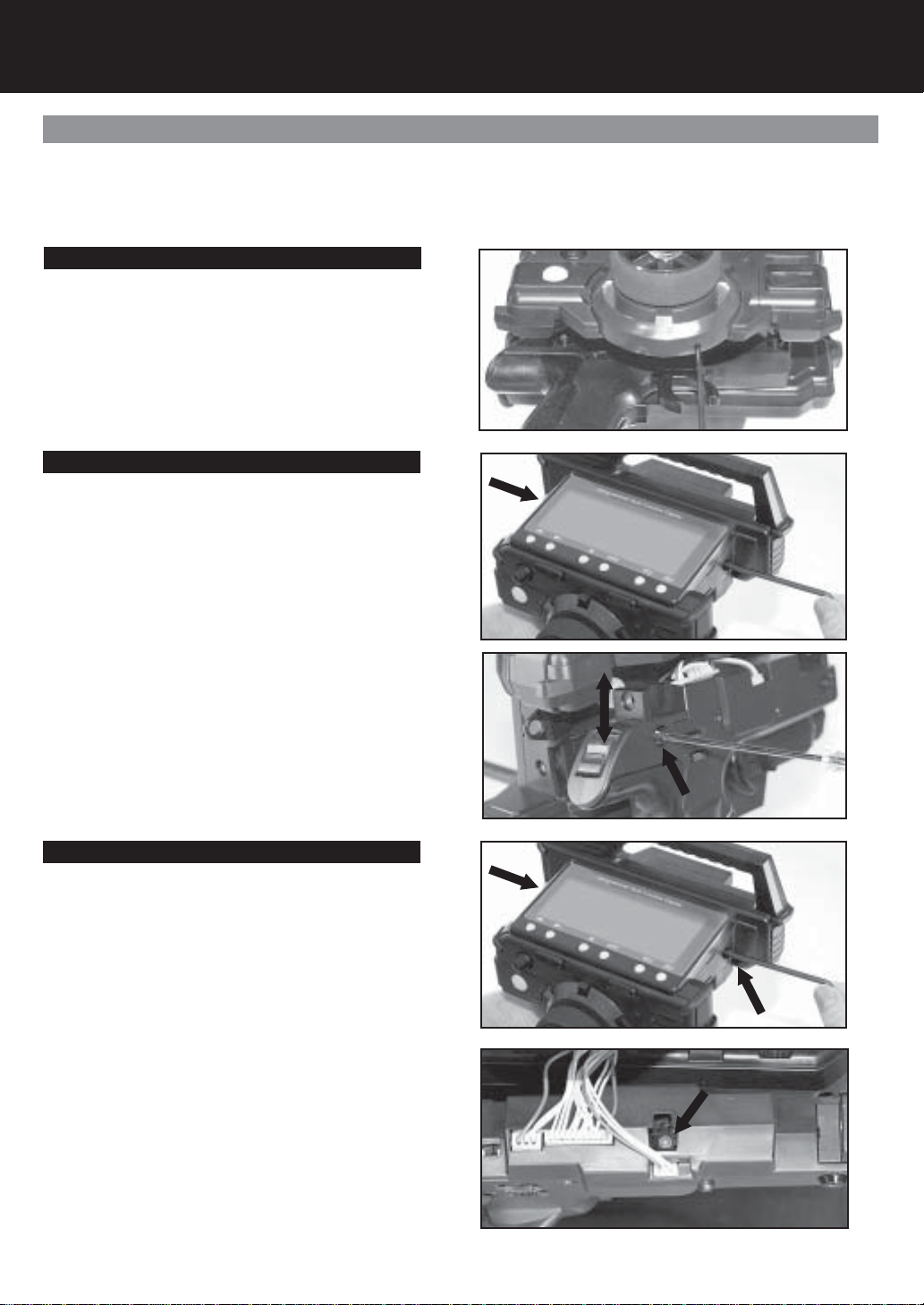
Steering Wheel Tension
The steering spring tension can be adjusted using a 1.5
mm hex wrench as shown in the photo. Steering spring
tension will increase as you tighten the hex bolt. Note: The
spring tension is factory set at the lowest (softest) position.
Driving Position
1. Remove the 4mm hex socket head cap screws on
each side of the transmitter using a 3mm hex wrench.
2. Detach the grip downward from the upper transmitter
unit. Be careful to avoid damaging the lead wires that
are connected on both units.
3. There are four (4) Phillips screws holding each side of
the grip bracket. Remove the screws and reset the
bracket screw hole at the lower screw hole. This sets the
bracket to the higher height position. Note: The grip
bracket is factory set to the lower height position.
4. After resetting the driving position, retighten the grip
bracket screws. Attach the upper part of the transmitter
unit into position with two (2) 4mm hex socket head cap
screws and a 3mm hex wrench.
Throttle Trigger Tension
1. Remove the 4mm hex socket head cap screws on each
side of the transmitter using a 3mm hex wrench.
2. Detach the grip downward from the upper transmitter
unit. Be careful to avoid damaging the lead wires that are
connected on both units.
3. Adjust the throttle trigger spring tension using a 1.5 mm
hex driver. Location of the 1.5mm hex bolt is shown in
the photo. Throttle trigger spring tension increases as
you tighten the hex bolt. Note: The spring tension is
factory set to the lowest (softest) position.
4. After resetting the throttle trigger spring tension, align the
upper transmitter unit into place. Tighten using the 3mm
hex wrench and two (2) 4mm hex socket head cap
screws per side.
Page 1
Before Using the M11 (Cont)
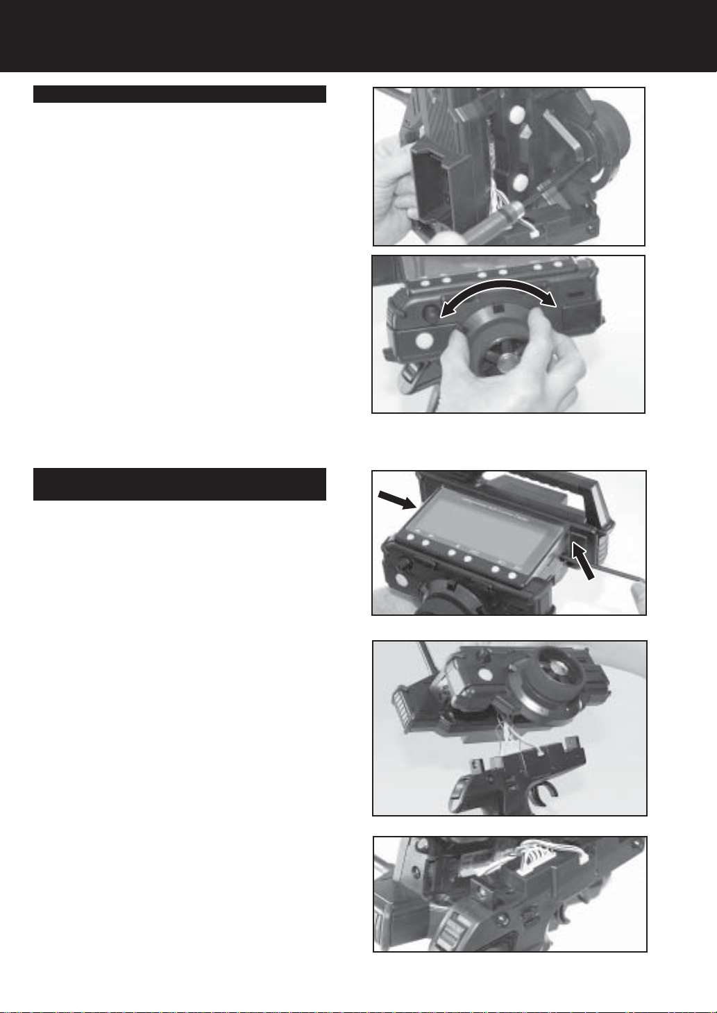
Trim Position
Trim position may be adjusted (5 positions) by rotating the
trimmer unit.
1. Remove the 4mm hex socket head cap screws on each
side of the transmitter by using a 3mm hex wrench.
2. Detach the grip downward from the upper transmitter
unit. Be careful to avoid damaging the lead wires that
are connected on both units.
3. Remove the three hex socket head cap screws (M2.6)
from the backside of the trimmer unit (i.e. behind the
steering wheel as shown on the photo.)
4. Rotate the trimmer unit to the desired position. Trim
position may be selected from fi ve (5) positions. Set the
trimmer unit at optimum trim position. After selecting the
position, retighten the hex socket head cap screws
(M2.6).
5. After resetting the trimmer position, attach the upper
transmitter unit back into place. Tighten using a 3mm
hex wrench and two (2) 4mm hex socket head cap
screws per side.
Switching Right Driving position to Left Driving
Position (Dominant hand)
In order to change to a left handed driving position, rotate
the grip as follows:
1. Remove the 4mm hex socket head cap screws on each
side of the transmitter using a 3mm hex wrench.
2. Detach the grip downward from the upper transmitter
unit. Be careful to avoid damaging the lead wires that
are connected on both units.
3. Set the Left/Right selector switch to L. located above
TRM 4 and TRM 5.
4. Rotate the grip by 180 degrees.
5. After rotating the grip, align the upper transmitter unit into
place. Tighten using a 3mm hex wrench and two (2)
4mm hex socket head cap screws per side.
Page 2
NiCd Batteries
Safety Precautions When Charging A NiCd Battery. (Optional part)
CAUTION!
* Please read the charging procedures listed below to ensure safe and correct use of your NiCd battery.
* The battery is not charged when purchased. It is necessary to charge the battery before operation.
* Before charging NiCd batteries, double check power switches are in the off position on the transmitter and/or receiver.
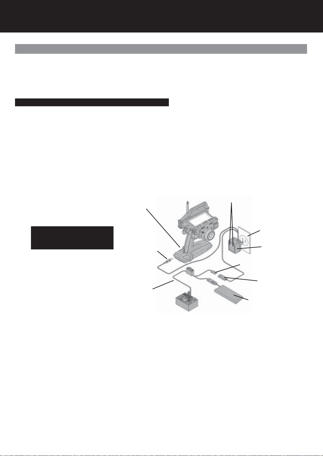
Charging the Transmitter/Receiver NiCd Batteries.
1. Connect the supplied charger to AC power outlet.
2. Charging the transmitter NiCd battery: Connect the round charger jack to the transmitter-charging outlet.
3. Charging the receiver NiCd battery: Connect the square plug from the charger to the connector on the switch harness, or
NiCd battery, depending on your setup.
* Make sure that the charging indicator LED light is on.
Charging a battery for the specifi ed period may not result in a full charge if you have a new battery or have not used the battery for
an extended period of time. In this case, you can activate the battery for use by running it through two or three charge cycles.
Charging Indicator Lights
Optional NiCd Battery Installed
NOTE: The receiver plug can not be
used to charge the transmitter NiCd
battery pack when the battery pack is
out side the transmitter.
Switch harness with DSC
WARNING: To prevent serious personal injury and/or damage to property, you must observe the following precautions
when handling NiCd batteries.
Incorrect use can result in electrolyte spills, overheating, and bursting.
* Use only SANWA optional charger for charging your NiCd batteries and never charge for more than the specifi ed amount of
time.
* Overcharging damages a battery and can result in overheating, bursting, and electrolyte spillage. This may cause personal injury
and/or to property (i.e. burns, fi re, or damage to the eyes.)
* When connecting the charger connector to the receiver NiCd battery or switch harness, be careful to avoid reversing the polarity
or shorting the connector.
* Do not dispose of the battery in any fi re or allow it to overheat.
* Do not short-circuit the positive terminal or the negative terminals with wire or any other object.
* Do not remove the outer tube. This is for protection and prevents scratches or other damage.
* Do not throw the battery or abuse it in any manner.
Round TX Plug
AC power outlet
Optional Charger
Charging Connector
Flat RX Plug ONLY
Optional NiCd Battery
4.8 or 6.0 volts
Page 3
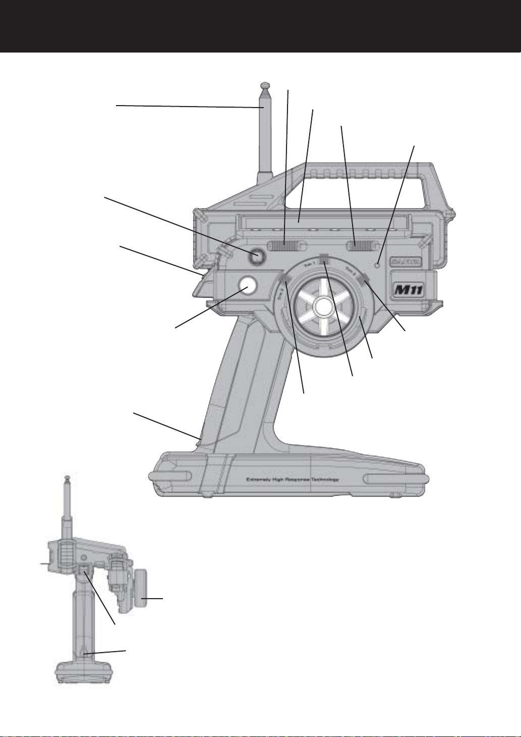
Transmitter Features and Controls
Display Switch
Antenna
Dial Knob
Power Switch
Push Button Switch (SW1)
Display Panel
Key-Lock Switch
Power Indicator Light
Trim Control (TRM3)
Steering Wheel
Trim Control (TRM1)
Charging Jack
Power Switch
Trim Control (TRM2)
Steering Wheel
Charging Jack
Page 4

TX Module
Throttle Trigger
Direct Servo Control Jack (DSC)
Push Button Switch (SW2)
Push Button Switch (SW3)
Page 5
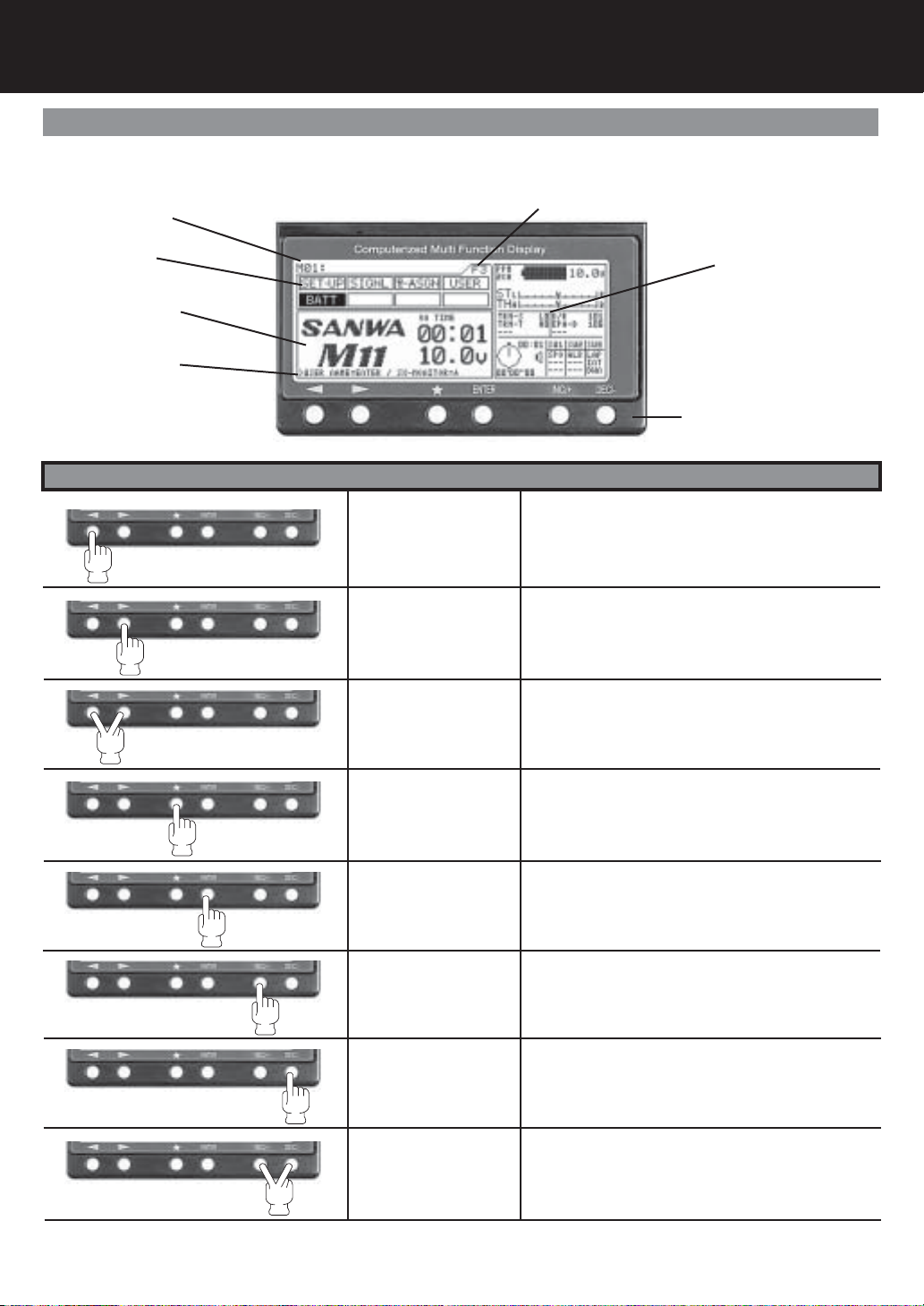
Key Pad Menu Buttons
Using the Key Pad Menu Buttons
The M11 has 6 keys for menu operations. You will fi nd the use of the 6 keys summarized below.
Model Number
Function Page
Menu Function
Programming Area
HELP Display Area
Information Area
Key Pad
Key Name Function
Function select Key
(Left)
Function select Key
(Right)
Function Page select
Key sequence
Moves the Menu Function cursor left to the previous
(backwards) menu function.
Moves the Menu Function cursor right to the next
(forward) menu function.
Pressing down on both keys will scroll through function pages in order. F1, F2 and F3.
The menu function cursor will highlight the fi rst func-
tion on that page.
Page 6
Scroll Key
Ë
Enter Key
INC+ Key
(Increase)
DEC- Key
(Decrease)
INC+ and DEC-
(Reset)
Will move the menu key backwards in the programming area. Also used in the HELP display area.
Will move the menu key forward in the programming
area. Also used in the HELP display area.
Increases number values in programming area.
Scrolls up selection list.
Decreases number values in programming area.
Scrolls down selection list.
Resets selection to factory default setting.

Function Pages
Menu Function Pages / Information Area
The functions of the M11 span three pages, F1 to F3, and can be selected directly using just the < function > keys. The fi rst function
on successive pages can be easily displayed in the sequence F1 > F2 > F3 > F1 . . . by pressing the < function > keys at the same
time.
Function Menu Page 1
Function Menu Page 2
Function Menu Page 3
A constant display area is provided on the right side of the screen. This makes it possible to determine, at a glance, the current setting status of various functions from any menu screen. Further, you can display the servo monitor screen by pressing the key.
Number of Channels (2 or 4)
Steering Trim
Throttle Trim
Trm 1, Trm 2, Trm 3
Feature display and settings
Timer and Switch Status
Battery Remaining
Battery Voltage
Steering Dual Rate, Brake EPA and 3CH settings
Optional information screen can be
changed using the key.
Note: can only be changed when the
help screen shows SX-MONITOR
Ë
Ë
Page 7
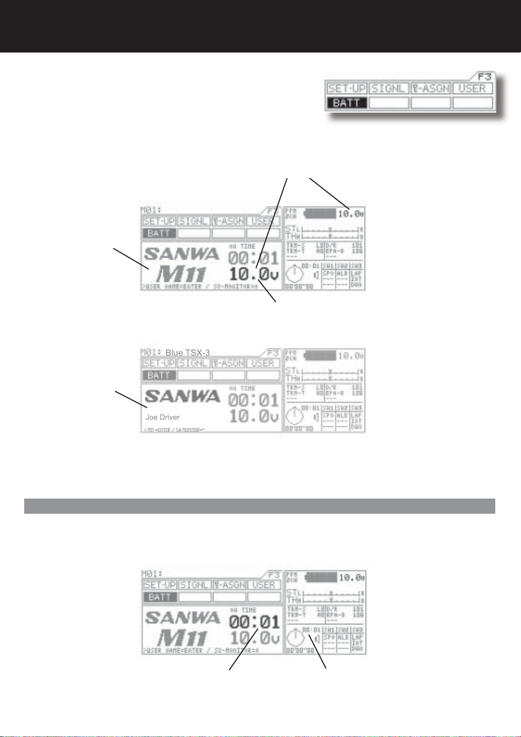
Battery / Operation Timer
The transmitter battery voltage can be seen in two separate windows
and measures 0.1 of a volt.
1. BATT Menu
2. Information Menu
Battery voltage indicator
M11 Screen
Page F3 (BATT)
NOTE: This area of the
information screen is not
programmable and will stay
}
on all the time.
In the BATT menu, you can press the
ENTER key to switch between the user
and M11 screens.
User Name Screen
When the transmitter battery runs down to 9.1 volts, the transmitter will start beeping and vibrating if the vibration feature is on and
will continue every 30 seconds. When this happens, promptly stop operation and charge or replace the transmitter batteries.
Will start blinking if battery reaches 9.1 volts or below.
Operating Timer
The operating timer is an up timer that records the time the transmitter has been on in hours and minutes. This timer can be reset to
00:00 by pressing both the (INC/+) (DEC/-) keys at the same time. Resetting the Operating timer after you have charged or replaced
the transmitter battery will give you the amount of time the current battery has been in use.
Page 8
Operation Timer in BATT screen Operation Timer on all the time.
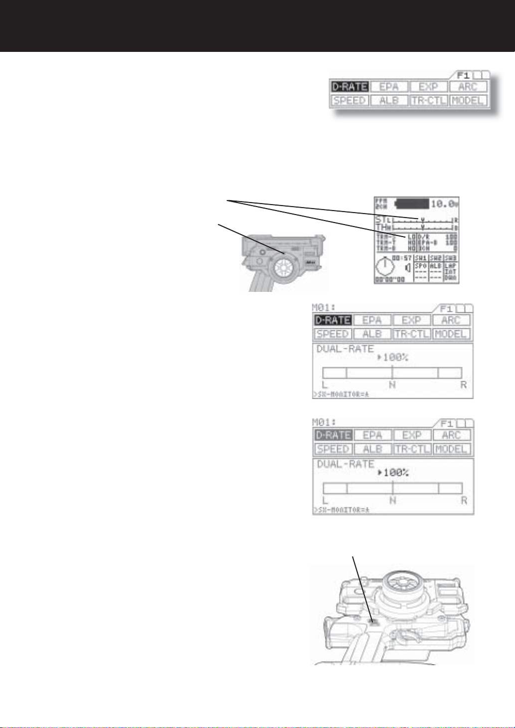
Dual Rate Steering
Dual Rate is used to change the amount of servo movement compared to the amount of movement with the steering wheel. Increasing the amount of dual rate will make the steering more sensitive or feel faster and decreasing the dual rate will make the steering
more insensitive or feel slower.
When setting up a new car or truck, follow the directions below to properly setup your steering dual rate.
1. Set the digital steering trim to “0” by using (Trm 1). You can see when the trim
reaches center by viewing one or both screens.
Steering trim factory default location: (Trm 1)
Press the function select key to move the cursor to (D-RATE). As you
2.
move the steering wheel from side to side, you can set the bar graph
move to the dual rate limit lines. Default setting is 100%.
Page F1 (D-RATE)
Adjust the dual rate by pressing the INC+ or DEC- keys to increase
or decrease dual rate amount. At this time, set the dual rate to 125%.
This will increase the servo movement by 25% in both left and right
directions.
NOTE: Pressing both the INC and DEC keys together will set the dual
rate to the default setting of 100%.
Attach the steering linkage to the servo arm as the car manufacturer
3.
recommends. Be sure to have all steering linkage, trim and the servo
arm as close to center as possible. Doing so will cut out a lot of steering problems later.
Now move the steering wheel left and right to full. If your steering
binds at both ends, this means you have too much movement coming
from the servo. Use the dual rate to reduce or increase the amount of
steerings to reach the steering stops.
4.
After the dual rate has been set, adjust the independent left and right
end points using the EPA feature.
Trm 4 (top)
Page 9
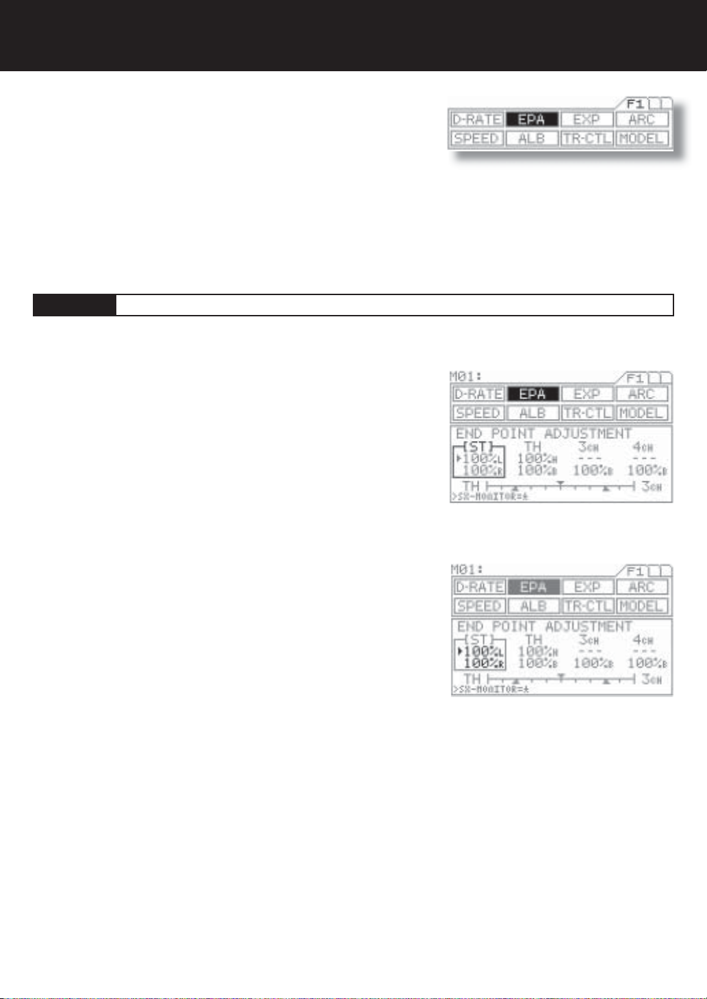
End Point Adjustment
End point adjustment is used to adjust the proper amount of servo movement on the model’s steering angle to steer left and right
and/or adjust the carburetor throttle arm stroke, the high point of an ESC and brake stroke.
While the M11 is set for 4 channels, this EPA function is also adjustable for the 3rd BRAKE or AUX Channel and the 4th channel
brake.
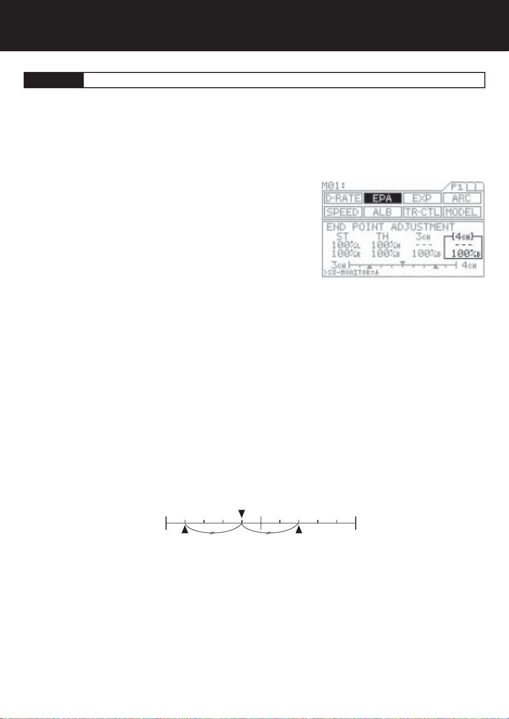
Page F1 (EPA)
[ST]
A model’s turning radius can differ from left to right because of variations in
linkage, suspension balance, tire diameter or weight distribution of the vehicle.
In such cases, the left and right servo steering angle is adjustable.
Before making the end point adjustment, you must set the servo to the neutral
1.
position. To fi nd the center position, adjust the servo horn to approximately the
center position, and then make fi ne adjustments using the sub-trim.
2.
Next, press the function select key and move the cursor to [ST] in EPA.
To set the steering end point on the right side, turn the steering wheel fully
3.
clockwise and depress the Inc.+ or Dec.- key. To set the left steering end point,
do the same with the steering wheel turned fully counterclockwise.
Setting range 0% to 150%
Default setting 100%
Steering End Point Adjustment
IMPORTANT
Note: Setting the steering dual rate and steering end points excessively high may cause a dead point on the servo, resulting in
improper operation.
Page 10

End Point Adjustment (Cont)
[TH]
Throttle end point adjustment is used to adjust the carburetor stroke, high point of an ESC, or the brake stroke.
1.
Press the function select key and move the cursor to [TH] in EPA.
2.
To adjust the high end of throttle movement on a gas powered car, pull the
throttle trigger all the way to the high side and adjust by pressing the Inc.+
or Dec.- key.
To adjust the brake side, push the throttle trigger all the way to the brake
side and adjust by pressing the Inc.+ or Dec.- key.
With an ESC, the high side and brake side are both ordinarily set to 100%
and then the high point and brake point are set on the ESC.
(Setting procedures may vary depending on the type of ESC.)
Setting range 0% to 140%
Brake side 0% to 160%
Standard setting 100%
3.
Test run your vehicle to set the brake adjustment by using TRM5 switch on
the grip. You can vary the setting at EPA-B by adjusting with TRM5. While
the M11 is set for 4 channels, setting value may vary at the same time.
Throttle End Point Adjustment
Trm 5 (bottom)
NOTE
With gas-powered model linkage, if the linkage stroke is set too wide, the servo
may lock up. This results in fatal damage and may cause the vehicle to runaway.
TIP
Brake adjustment TRM5 switch can be assignable with other trim switches.
Page 11

End Point Adjustment (Cont)
With 4-channel setting
[3ch]
NOTE: In order to set any functions for AUX 3 and AUX 4, you must fi rst set the channel setting from 2 to 4 channel. To change from
2 to 4 channel, go to the F3 page on the transmitter, move the function menu cursor to SET-Up and change the channel number in
the programming area on the transmitter screen.
The AUX channel can be used for functions such as needle control or for
other uses. The end point adjustment allows fi ne adjustments of the maxi-
mum servo travel. Further, the high end point and low end point can be set
independently, which provides great fl exibility of adjustment.
1.
Be sure that channel 4 is selected in the set-up menu and that 3CH-BRAKE
is set to INH in the BR-MIX menu. It is essential to set the M11 as “4channel”
in order to use these functions.
Press the function select key and move the cursor to [3ch] in EPA.
2.
To select the low side AUX setting, turn the dial counterclockwise and de-
3.
press the Inc.+ or Dec.- key. To select the high side setting, do the same after
turning the dial clockwise.
Setting range 0% to 150%
Standard setting 100%
TIP
The standard setting of the AUX channel is on the DIAL. * This dial can be
assignable with other trim switches such as TRM 1 to TRM5.
AUX End Point Adjustment ( with 3ch - BRAKE INH )
[3ch]
When using 3rd channel as the additional BRAKE channel, the end point adjustment can be separately set from the other BRAKE
channel.
1.
Make sure that channel 4 is selected in the set-up menu and that 3CHBRAKE is set to ACT in the BR-MIX menu. It is essential to set this function
in order to activate this set up menu.
2.
Press the function select key and move the cursor to [3ch] in EPA.
3.
Push the throttle trigger all the way to the brake side and then adjust by
pressing the Inc.+ or Dec.- key.
Setting range 0% to 160%
Standard setting 100%
4.
If it is necessary to change the EPA brake adjustment during the operation of
the vehicle, use trimmer TRM5 on the grip.
IMPORTANT
* Since this channel is exclusively for braking purposes, setting EPA covers only the BRAKE side.
3CH-BRAKE End Point Adjustment ( with 3ch - BRAKE ACT )
Page 12
End Point Adjustment (Cont)
[4ch]
The 4th channel is exclusively for braking purposes. When using the 4th channel as the additional BRAKE channel, end point adjustment can be separately set from the other BRAKE channel (3ch).
1.
Be sure that channel 4 is selected in the set-up menu. It is essential to set
this function in order to activate this set up menu.
Press the function select key and move the cursor to [4ch] in EPA.
2.
Push the throttle trigger all the way to the brake side and then adjust by
pressing the Inc.+ or Dec.- key.
Setting range 0% to 160%
Standard setting 100%
3.
If it is necessary to change the EPA brake adjustment, during the operation of the vehicle, use trimmer TRM5 on the grip.
IMPORTANT
Since this channel is exclusively for braking purposes, setting EPA covers only the BRAKE side.
4CH - BRAKE End Point Adjustment
TIP
Balance bar graph
The bar graph appearing at the bottom of the screen is useful when setting the brake on more than two channels.
The graph indicates the center position of two EPA values. Use it as a guide for fi nding a good brake balance. The lower triangles in
the graph indicate the respective EPA values.
When 3CH-BRAKE is set to ACT, the ENTER key switches the balance display between TH-3CH and 3CH-4CH. When 3CHBRAKE is set to INH, the bar graph shows only the TH-4CH balance.
TH 3CH
EPA of TH EPA of 3ch
Page 13

Exponential
This function varies the amount of servo action with respect to manipulation of the
steering wheel or throttle trigger based from the neutral position. Increasing the
numeric value makes action quicker, while reducing it makes action slower.
Page F1 (EXP)
Quick
(1% to 100%)
Normal
0%
Mild
(-1% to 100%)
Amount of servo operation
Amount of steering wheel operation
on the L side (amount of throttle
trigger operation on the H side)
[ST]
Three settings, Mild, Linear and Quick, allow you to set the most effective steering response for your model vehicle. Generally, if
your model vehicle over-steers, reduce the numeric value. If it under-steers, increase the numeric value.
1.
Press the function select key and move the cursor to [ST] in EXP.
Steering Exponential
Neutral position
Quick
(1% to 100%)
Normal
0%
Mild
Amount of servo operation
Amount of steering wheel operation
on the R side (amount of throttle
trigger operation on the B side)
(-1% to 100%)
2.
Set the EXP quantity by pressing the Inc.+ or Dec.- key.
Setting range -100% to 100%
Standard setting 0
TWEAK setting
3.
Use the TWEAK setting when you want to fi ne-tune the left-right steering bal-
ance.
First, move the cursor to below TWEAK with the ENTER key.
To adjust the left side steering, turn the steering wheel to the left and set the
cursor direction to <. To adjust the right side steering, turn the steering wheel to
the right and set the cursor direction to >.
Set the TWEAK quantity by pressing the Inc.+ or Dec.- key.
Setting range -20 to 20
Standard setting 0
Page 14