

Sanuvox SR+ User Manual
OPERATION
SR+
IMPORTANT: When the Sanuvox SR+ is turned on by pressing the POWER button, the RED LED on the POWER button will
illuminate and the status LED will flash in alternate colors singling the SR+ is warming-up. The warm-up will last approximately 45
seconds, after which time the unit will enter ‘STANDBY-MODE’. THE UNIT WILL NOT FUNCTION UNTIL THE WARM-UP IS
COMPLETE.
1. Once the SR+ is in ‘STAND-BY’ mode, the unit will be waiting for airflow in order for the UV Lamp to turn ON. The SR+ has a built-in
Thermistor that controls operation. When there is airflow the Thermistor changes temperature causing the SR+ Lamp to come on. When
airflow stops, the SR+ UV Lamp will turn OFF accordingly.
2. When in ‘STAND-BY’ and there is airflow, the SR+ UV Lamp will come ON and the LED will illuminate GREEN.
3. When there is no airflow, the status LED will be OFF and the RED POWER Button LED will remain ON.
UNDERSTANDING THE LED STATUS DISPLAY
LED Solid GREEN = SR+ is ON with UV Lamp ON sensing airflow
LED Flashing GREEN = Warm up sequence lasting up to 45 seconds
LED Flashing ORANGE = UV Lamp has functioned for 3 years and is due for replacement.
INSTALLATION
MANUAL
LED Solid RED = UV Lamp has FAILED. Must be replaced
+
LED Alternating RED+GREEN = Thermistor Issue
LED OFF = Unit is on Stand-by (provided RED power button LED is illuminated)
NOTE: The only time the RED Power button LED will be OFF is if power is interrupted to the
unit or the Power Button is in the OFF position.
WARRANTY
The SR+ carries a three (3) Year Warranty on the unit and a three (3) Year Warranty on the UV Lamp.
Troubleshooting the UV Lamp
To check to make sure the UV Lamp has in fact failed:
Disconnect the plug from the Lamp.
Placing the probe of the ohmmeter to one of the four pins on the end of the Lamp, touch the other probe of the ohmmeter to each of the other pins
until you find the matching pin. The ohmmeter shows continuity (closed circuit). This indicates that the filament is good. Check the other two pins. If
both sets of filaments test OK (continuity), the Lamp is functioning. If one or both sets of filaments read an open circuit (no continuity) on resistance,
the Lamp must be replaced.
WARNING
Before installing or performing maintenance or
service on the purifier, turn off unit and disconnect
from power source. Electrical shock can cause
injury or death. There may be more than one
disconnect switch.
WARNING
Never expose eyes or skin to ultraviolet light from
any source. The Purifier MUST be DISCONNECTED
from power source before performing maintenance
or service. Personal injury may result.
WARNING
Do not touch Lamp glass without gloves. Reduced
performance of Lamp may result. Clean Lamp after
handling.
WARNING
The UV Lamp contains a small quantity of mercury.
If a Lamp breaks, clean and dispose of with care.
Follow all safety codes.
Wear safety glasses and work gloves.
PLEASE SAVE FOR YOUR RECORDS
Serial Number#
Date Installed:
Installed By:
Installers Contact info.:
UV LAMP RESET BUTTON (To be used to reset “Days Left” after UV Lamp change-out)
To the bottom right of the SR+ cover right you will see a small REST hole. To RESET the UV Lamp Replacement LED Reminder back to 3 years,
insert a small object similar to a paper clip into the hole holding down the button for 3 seconds.
1-888-SANUVOX www.sanuvox.com
WARNING
Use only specified replacement Lamps with you
Purifier. Use of an incorrect Lamp can result in
damage to the Purifier and/or Lamp.
04/13 V.4
SANUVOX TECHNOLOGIES INC. © 2013
1-888-SANUVOX www.sanuvox.com
SAFETY CONSIDERATIONS
Only trained and qualified service personnel should install, repair, or service HVAC equipment. Untrained personnel can perform basic maintenance
functions such as changing Lamps. Trained service personnel should perform all other operations. When working on HVAC equipment, observe
precautions in the literature, tags and labels attached to the unit or accessory, and other safety precautions that may apply. Follow all safety codes.
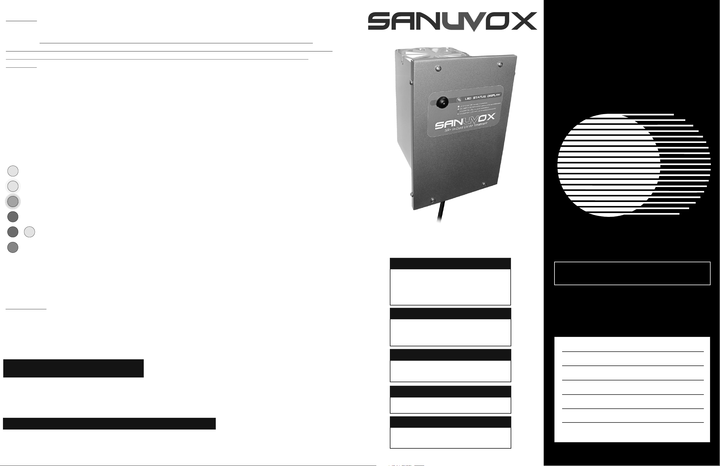
INCLUDED IN THE BOX:
Installation Kit
SUPPLY SIDE INSTALLATION
NOTE: If installing over a heating source : The SR+ uses a built-in thermistor to sense airflow. The thermistor is set at 80°celcius (176°
Fahrenheit) when airflow passes over the thermistor, the thermistor cools slightly to switch the SR+ on. This is an effective method in controlling
the SR+ especially with new high efficiency variable-speed fans. Because the thermistor is sensitive to temperature change, if installing the SR+
on the supply side, install the SR+ far enough away from the heating source that the air will be less than 80°celcius (176° Fahrenheit).
Follow Steps 1-2 for Return side Installation
- Gloves
- Installation Instructions
- 6 x Self-Tappping Hexagon 1/4 Sheet Metal Screws (#8)
- 4 x Stainless Steel Phillips Screw 8-32 1/2"
Sanuvox SR+
UV ‘J’ Lamp
Frame
RETURN SIDE INSTALLATION: STEPS 1-7
NOTE: If the SR+ is to be installed on the SUPPLY side please refer to “Supply Side Installation”on opposite page
Location: The preferred location for installation of the Sanuvox SR+ UV System is in the return duct as the air will be treated before the filter and coil.
Make sure site can be supplied with the necessary power requirements. The SR+ should preferably be plugged into a conditioned dedicated 110V
outlet. If one is not available, an extension cord may be used. If the SR+ is to be installed on 220V, undo the four side screws to gain access to the
ballast and switch the ballast from 110V to 220V (there is a small switch on the ballast itself) & cut the plug to hard wire to 220V supply. Direct UV
exposure is dangerous to plastics. Wrap exposed plastic and wiring to shield from direct UV exposure (The Sanuvox wire-set is Teflon coated which
makes them resistant to UV exposure). The purifier can be mounted in a horizontal or vertical position (in the same direction of airflow). More than one
unit can be used in homes equipped with more than one air handler.
1
2
3
Reflecting Tube
4
5.5”
Turbulator
5
8.5”
3
Return side Clamp Post (Default)
Return side Clamp Post (Default)
Supply side Clamp Post
Supply side Clamp Post
For supply side or up-flow systems, the
SR + sh ips as a defau lt R ETURN
installation unit. If the SR+ is to be installed
in another orientation (i.e. supply side, up-
flow, etc.) the UV Lamp clamp must be
installed on the opposite threaded post with
the Reflecting Tube re-installed with the
Turbulator facing into the airflow.
B
A
B
4
Reflecting Tube
Turbulator
Reinstall Reflecting Tube with Turbulator
facing into the airflow.
Follow the remaining steps 5-7 on the
RETURN SIDE INSTALLATION.
A
B
Supply Installation
Airflow moves upward
through Turbulator
Turbulator
Ca ref ully re mov e UV
Lamp from packaging.
Use incl. cotton gloves to
guarantee a clean Lamp
after handling.
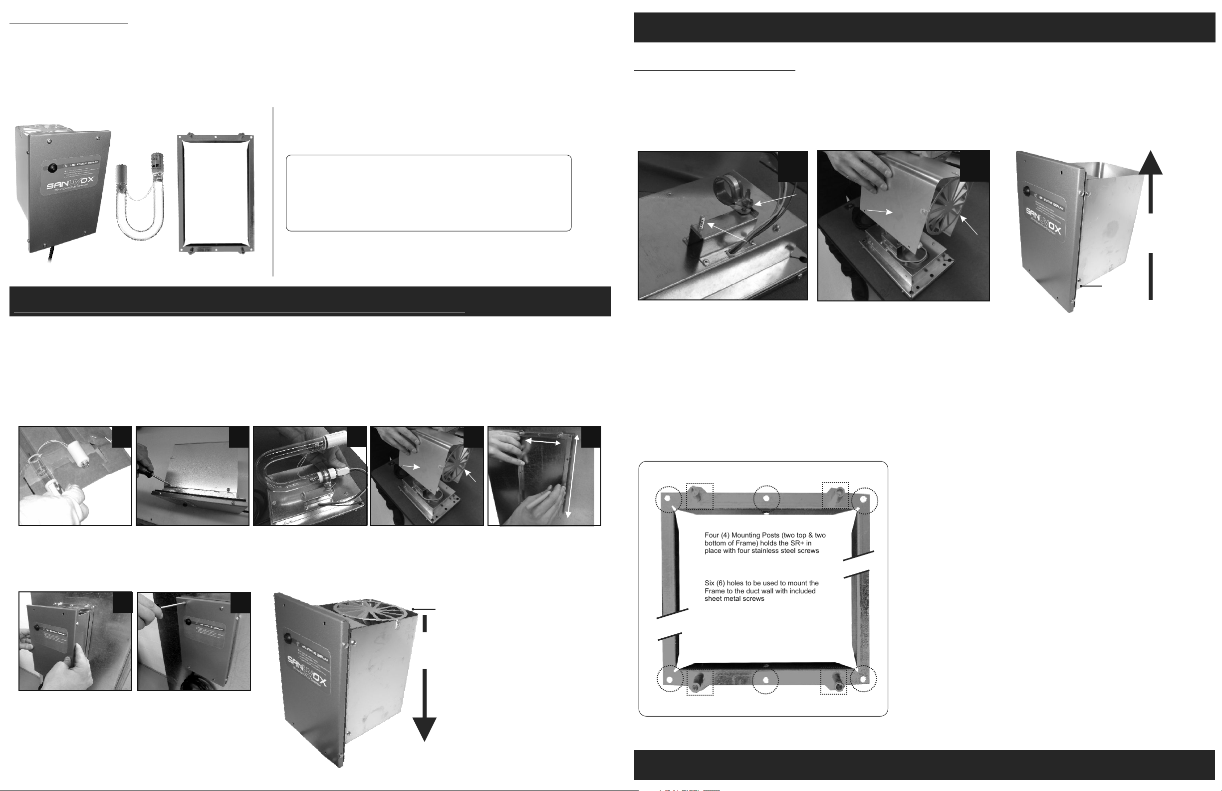
6
Mount the Support Frame
to the duct using the six (6)
Sheet Metal Screws. Once
the frame has been
mounted, insert the SR+
guided by the four (4)
mounting posts.
See Figure A.
To ins tal l U V Lam p,
remove Reflecting Tube
by removing the four (4)
screws on both sides of
the Reflecting Tube.
7
Secure the SR+ to the
frame with the four (4)
Stainless Steel Phillips
Screws
Insert UV Lamp with the 4
pin end into the clamp
assembly. Do not over
tighten wing nut. Plug the
Lamp into the white plug.
Re-install the Reflecting
Tube. Ma ke sur e th e
Turbulator will be facing
into the airflow.
Turbulator
Return Installation
Airflow moves downward
through Turbulator
To mount the frame, take
the frame support and
draw an outline on the
inside of the frame onto the
duct. Allow for a 1/8" space
around the marking. Cut
the hole which should
measure 5.5" x 8.5".
Four (4) Mounting Posts (two top & two
A
bottom of Frame) holds the SR+ in
place with four stainless steel screws
Six (6) holes to be used to mount the
Frame to the duct wall with included
B
sheet metal screws
Figure A.
SR+ Support Frame
B
A
B
B
A
1-888-726-8869 www.sanuvox.com
 Loading...