

Sanuvox SABER16/24-GM2 Installation Instructions Manual
WARNING
Before installing or performing maintenance or service on
the purifier, turn off unit and disconnect from power source.
Electrical shock can cause injury or death. There may be
more than one disconnect switch.
__________________________
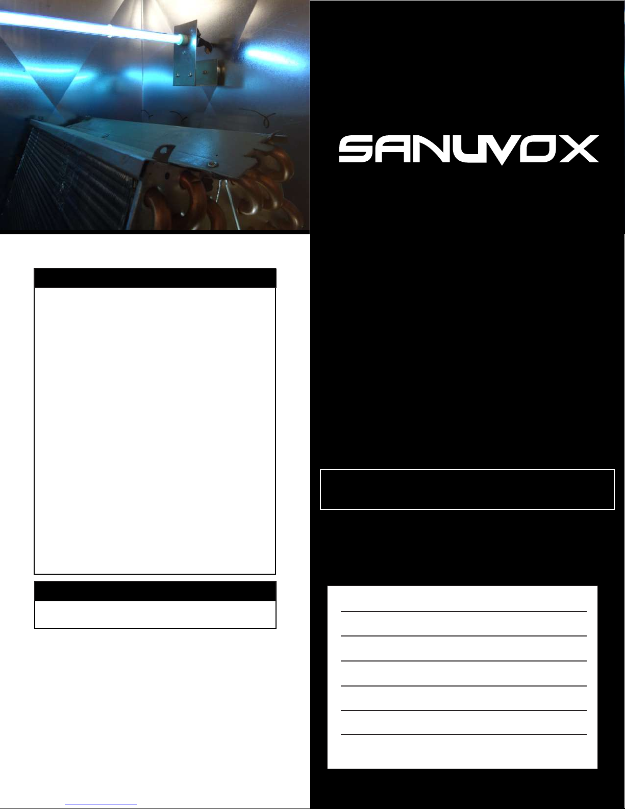
SANUVOX 24V UV LAMP SYSTEM
INSTALLATION INSTRUCTIONS
Model# SABER16/24-GM2
Saber 24V Ultraviolet Lamp Magnet System
Never expose eyes or skin to ultraviolet light from any
source. The purifier MUST be DISCONNECTED from power
source before performing maintenance or service. Personal
Do not touch lamp glass without gloves. Reduced
performance of lamp may result. Clean lamp after handling.
The UV lamp contains a small quantity of mercury.
If a lamp breaks, clean and dispose of with care.
Use only specified replacement lamps with your p
Use of an incorrect lamp can result in damage to the purifier
UV rays may destroy certain type of filters (polymer or
plastic), please keep units away from shinning directly on
injury may result.
__________________________
__________________________
__________________________
urifier.
and/or lamp.
__________________________
plastic.
NOTICE
UV lamp can be disposed/recycled after use as for
any other fluorescent bulb.
Follow all safety codes.
Wear safety glasses and work gloves.
PLEASE SAVE FOR YOUR RECORDS
Date Code#
Date Installed:
Installed By:
Installers Contact info.:
SANUVOX 24V UV LAMP SYSTEM
INSTALLATION INSTRUCTIONS
1. Disconnect power to the HVAC unit.
2. Remove the ballast, brackets, UV lamp retaining ring, view port, and UV lamp from the package.
3. Locate the ballast so that there is sufficient cable to attach to the UV lamp when it is installed.
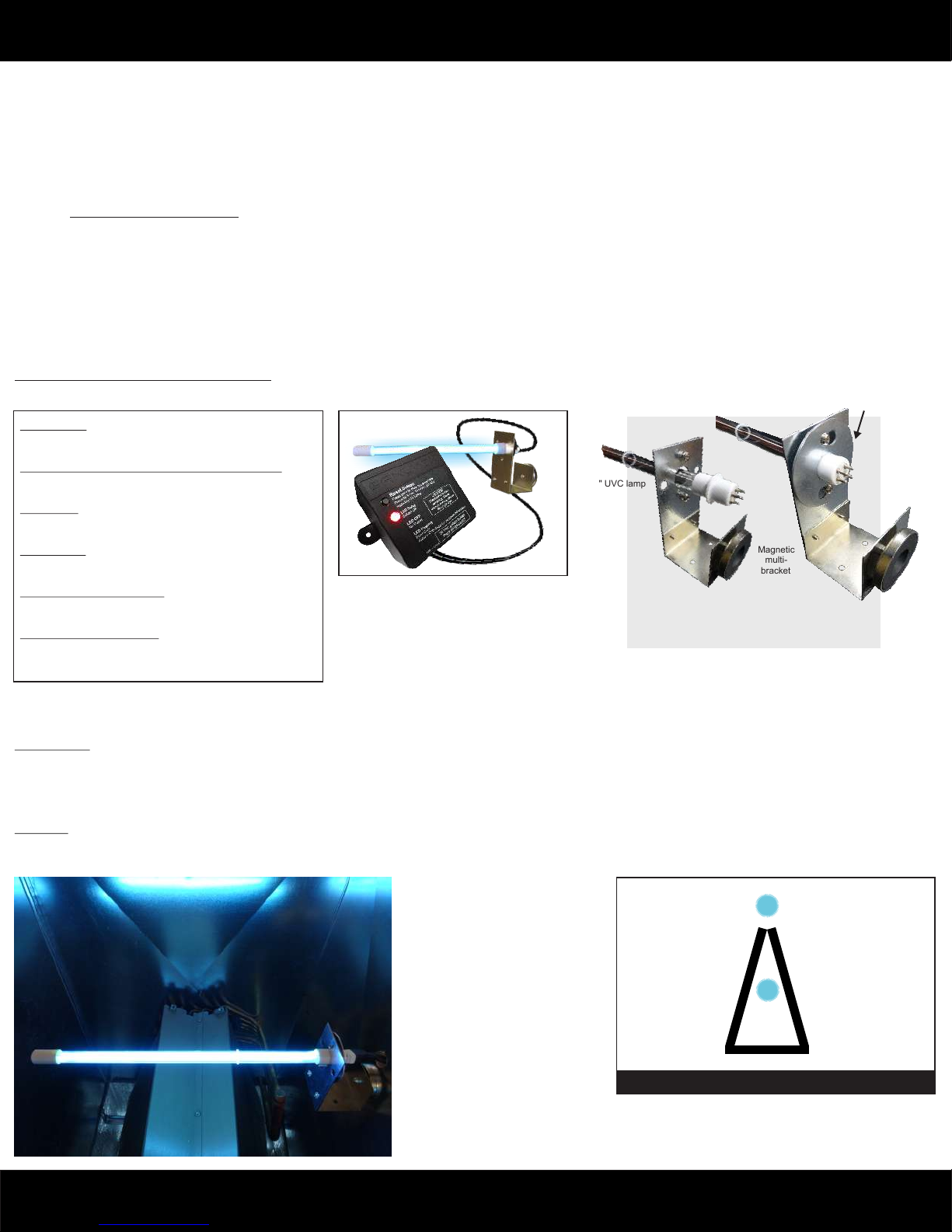
4. The two piece lamp bracket is used to hold the lamp. Depending on the type of coil and the location of the UV light on the coil will determine if one or both
5. The main bracket can be mounted to the side of the coil allowing the UV lamp to be inserted in-between or over the coil. Drill a 1” diameter hole in the sheet
6. Connect the plug onto the lamp pins. The plug is designed so that it can only be installed one way. You may have to rotate the socket 90 degrees to line up
7. Drill a ¼ inch hole on the outside of the plenum on one side of the coil and install the view port. When the UV lamp is operational, the glow of the lamp will be
8. Connect the black and white wires to the 24VAC terminals on the HVAC equipment. Make sure that the HVAC equipment can at least supply 20VA. If not we
9. Reconnect power to the HVAC unit or plug in the transformer in a power outlet.
pieces of the bracket are used. The UV lamp will be installed either with the lamp on top of the coil or the lamp inside the coil.
metal to allow the UV lamp to pass and mount the main bracket to the side of the coil using the two included sheet metal screws. Once installed use the
round metal lamp retaining ring to lock the lamp in place and tighten the two screws.
Use of magnetic multi-bracket: The magnetic multi-bracket allows for various lamp installations. Inspect the ideal location for the UV lamp system
and use the main bracket and magnetic multi-bracket together if desired.
the pins with the holes.
visible through this port.
recommend the use of a dedicated transformer that provides 24VAC with a minimum of 20VA otherwise it will not be sufficient to power the ballast and lamp.
Ballast Operation, LED Notification & Reset
The 24V ballast is equipped with an LED status notifying the user of various system conditions. The LED notifications work as follows:
Lamp
retaining
ring
System OK
LED Solid
Lamp > 8,700 hrs. (time to replace UV Lamp)
LED FLASH 1 sec. / pause 1 sec. Repeat.
16" UVC lamp
Lamp Fail
LED FLASH 2X / pause 1 sec. Repeat.
Ballast Fail
LED FLASH 3X / pause 1 sec. Repeat.
Magnetic
multi-
bracket
Low Voltage (under 18V)*
LED FLASH 4X / pause 1 sec. Repeat.
High Voltage (over 30V)*
LED FLASH 5X / pause 1 sec. Repeat.
Insert UV lamp into bracket and place
UV lamp retaining ring, lock into place
and tighten both screws.
*Connect w/ step-down transformer. Sold separately.
RESET BUTTON: To reset an error code, press RESET button once. Following a lamp replacement, press and hold the RESET button for 3 seconds to reset the 1
year timing function.
Maintenance
Disconnect all power before performing any maintenance or service. The UV lamp should be cleaned every two to three months. To clean, disconnect white socket
from lamp. Loosen the 2 screws on the retainer ring. Turn retainer ring left. Pull out retainer ring and pull lamp out. Wipe lamp with a soft tissue and alcohol based
solution. Reverse the above procedure to reinstall the lamp. Lamp needs periodic replacement to maintain design specifications. Replace lamp after 1 year of
operation. Follow instructions for ballast operation (above) on how to reset the timer feature. Contact a local dealer for replacement lamps.
Warranty
UV Lamp, 1 year warranty. Ballast, 5 years warranty.
1-888-726-8869
REPLACEMENTS PARTS
Lamp :
Ballast :
LMPRGPT160T5
BST24G48ET
Transformer : MSCTFR12024
120 - 24 V
Sample Installations
Example 1
Over the coil
(parallel or perpendicular)
Example 2
Inside the coil
Evaporator Coil
CAUTION: UV exposure is dangerous to eyes, skin
www.sanuvox.com
 Loading...