

Page 1

International Assembly Instructions for model WMS2
ENGLISH
ESPAÑOL DEUTSCH FRANÇAIS ITALIANO Русский
Spanish German French Italian Russian Japanese Mandarin
Sanus Systems 2221 Hwy 36 West, Saint Paul, MN 55113 USA 08.03.05
Customer Service: (800) 359-5520 • (651) 484-7988 • fax (651) 636-0367
Customer Service Europe: +31 - (0)40 26 68 619 • fax +31 - (0)40 26 68 615
See complementary Sanus products at www.sanus.com
中文
Page 2

Page 3
Assembly Instructions for Model: WMS2
Thank you for choosing a Sanus Systems WMS2. The WMS2 is designed to hold a bookshelf speaker up to 12" (30.5 cm) deep and
weighing 15 lbs. (6.8 kg.).
Safety Warning: If you do not understand these directions, or have any doubts about the safety of the installation, please call a
qualified contractor or contact Sanus at 800.359.5520 or www.sanus.com. Check carefully to make sure that there are no missing
or defective parts. Our customer service representatives can quickly assist you with installation questions and missing or damaged
parts. Replacement parts for products purchased through authorized dealers will be shipped directly to you. Never use defective parts.
Improper installation may cause damage or serious injury. Do not use this product for any purpose that is not explicitly specified by
Sanus Systems. Sanus Systems can not be liable for damage or injury caused by incorrect mounting, incorrect assembly, or incorrect use.
Please call Sanus Systems before returning products to the point of purchase.
Required Tools: Drill, 3/16" (0.5 cm) drill bit and a socket set
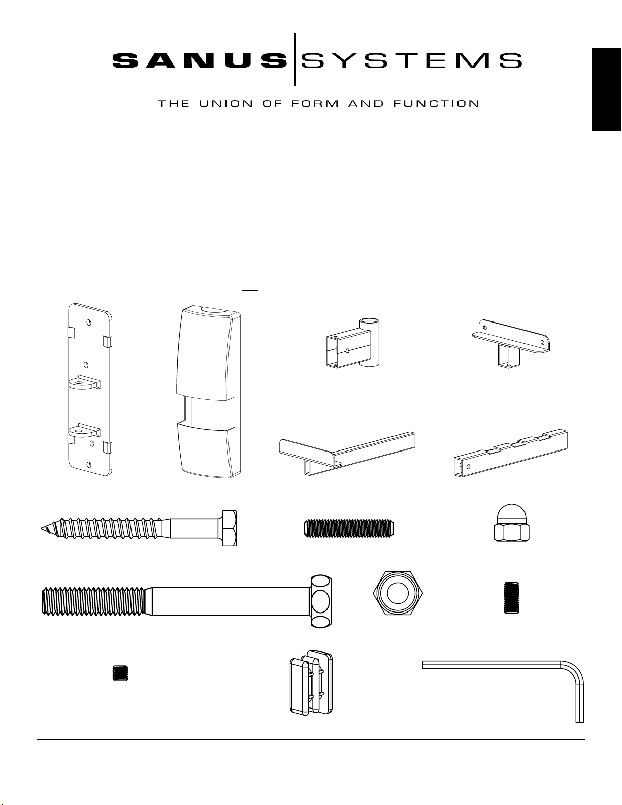
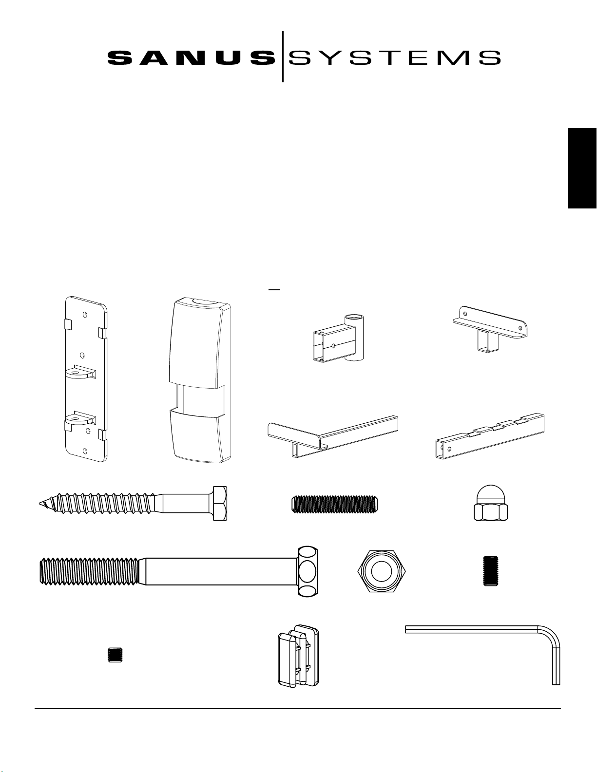
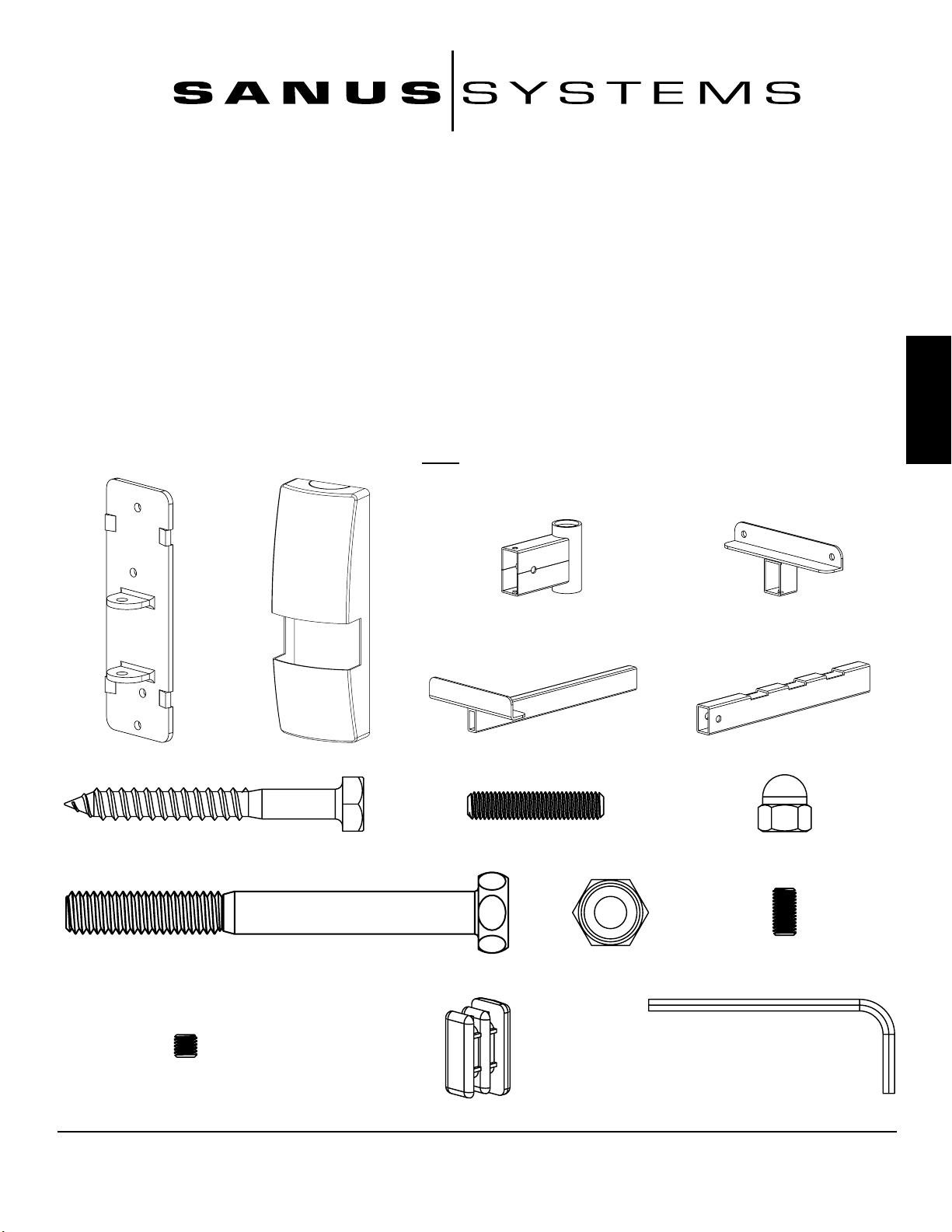
Supplied Parts and Hardware: Some parts not shown as actual size*
ENGLISH
(2) Pivot - c* (2) Foot - d*
(2) Wall Plate - a* (2) Cover - b* (2) Extension - e* (2) Arm - f*
(8) Lag Bolt - g (2) Threaded Stud - h (4) Acorn Nut - i
(2) Pivot Bolt - j (2) Pivot Nut - k (6) Long Set Screw - l
(2) Short Set screw - m (1) Allen Key - o
(2) Cap - n
Sanus Systems 2221 Hwy 36 West, Saint Paul, MN 55113 USA
Customer Service: 800.359.5520. See complementary Sanus products at www.sanus.com
Page 4
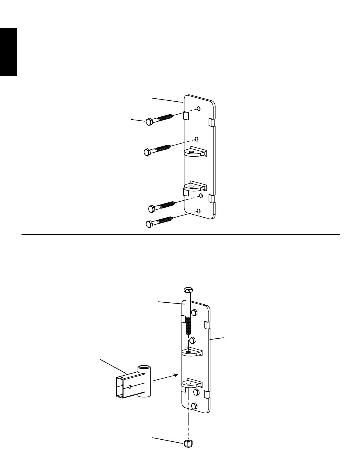
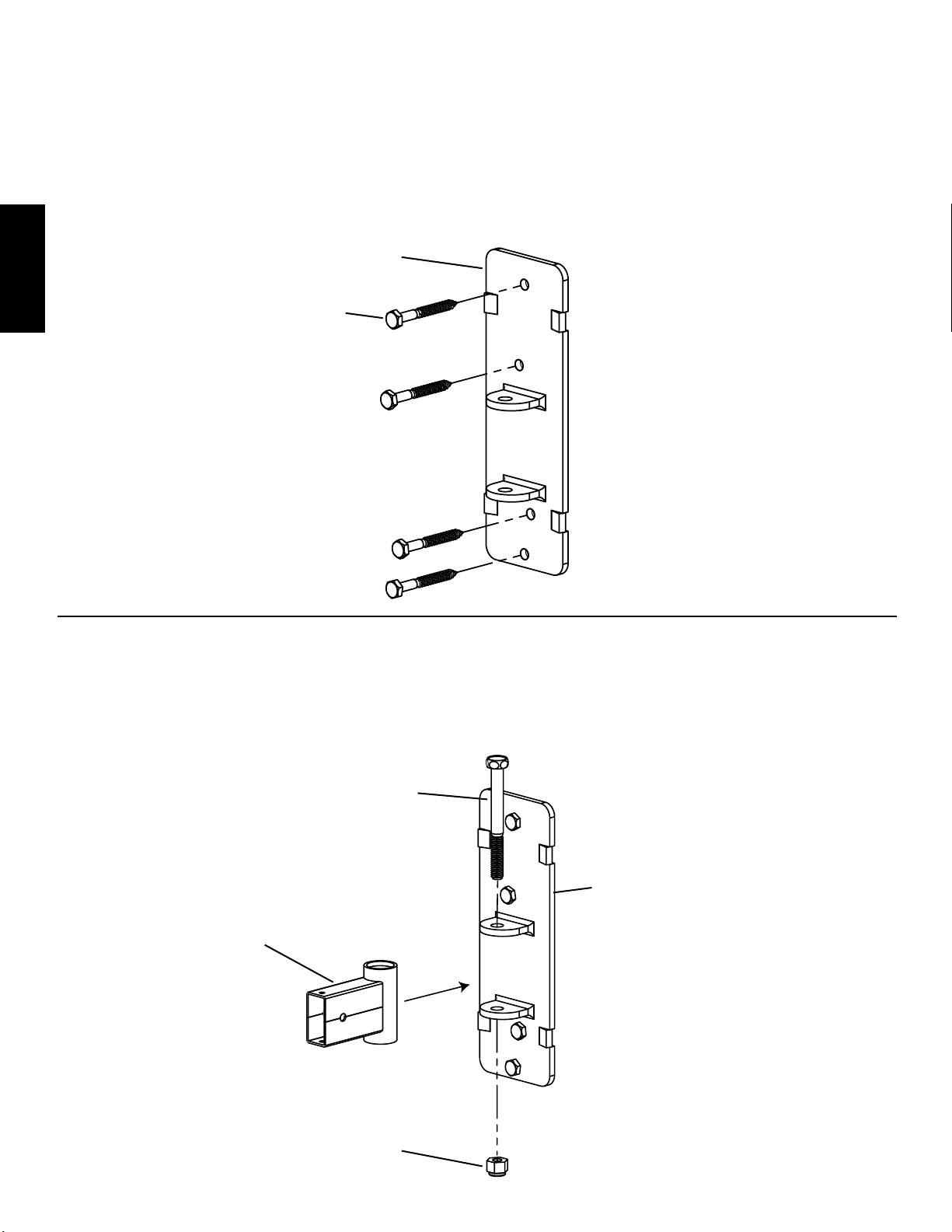
Step 1: Attach Wall Plate
The Wall Plate (a) must be mounted to a wood stud. Make sure the Wall Plate is oriented so that the flat side is against the wall and
the two tabs are closer to the bottom. Use the Wall Plate as a template to mark the 4 hole locations for the Lag Bolts (g) between the two
edges of the chosen stud. Pre-drill four holes 2.5" (6.4 cm) deep at the marked locations using a 3/16" (0.5 cm) drill bit. Attach the Wall
Plate to the wall using all four of the Lag Bolts. Tighten each Lag Bolt with the appropriate socket head. See Diagram 1 for assistance.
WARNING: Tighten Lag Bolts only until the Wall Plate is pulled rmly against the wall. DO NOT OVER-TIGHTEN
ENGLISH
THE LAG BOLTS!
Diagram 1
a
g
Step 2: Install Pivot
Insert a Pivot Bolt (j) down through the top tab in the Wall Plate (a), the Pivot (c), the lower tab in the Wall Plate, and finally thread it
into the Pivot Nut (k). Firmly tighten the Pivot Nut with the appropriate socket. See Diagram 2 for assistance.
Diagram 2
j
a
c
k
Page 5
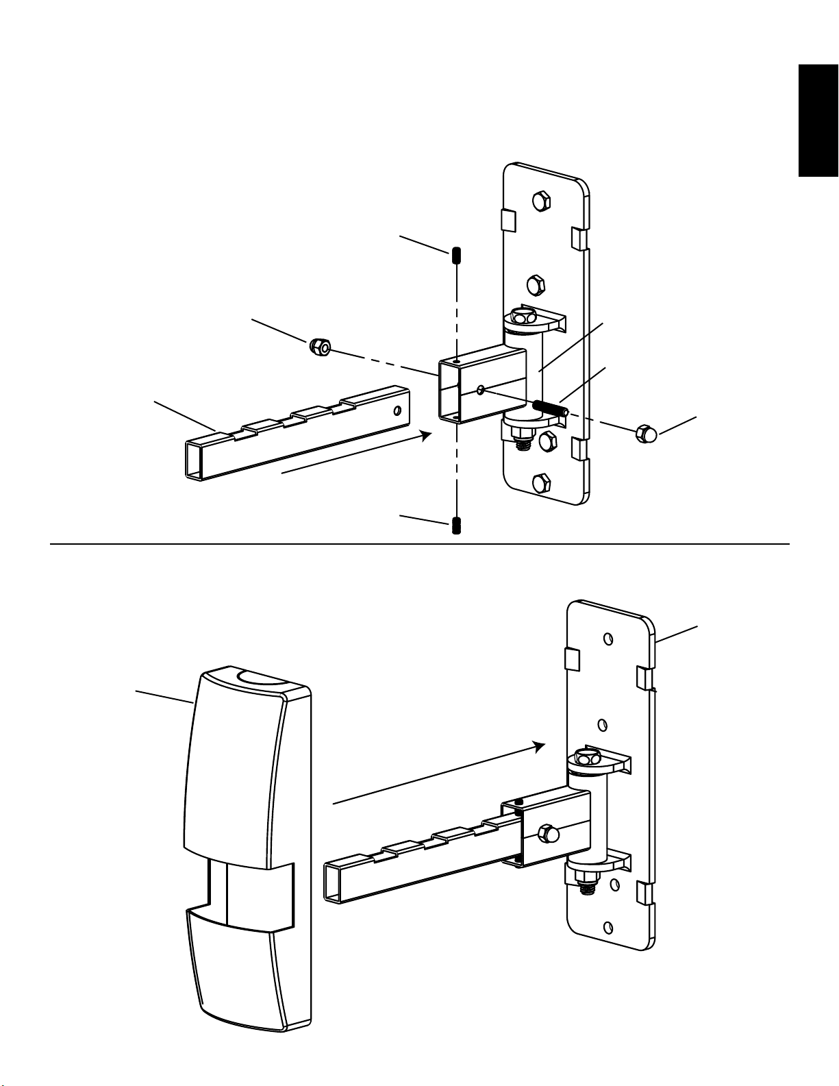
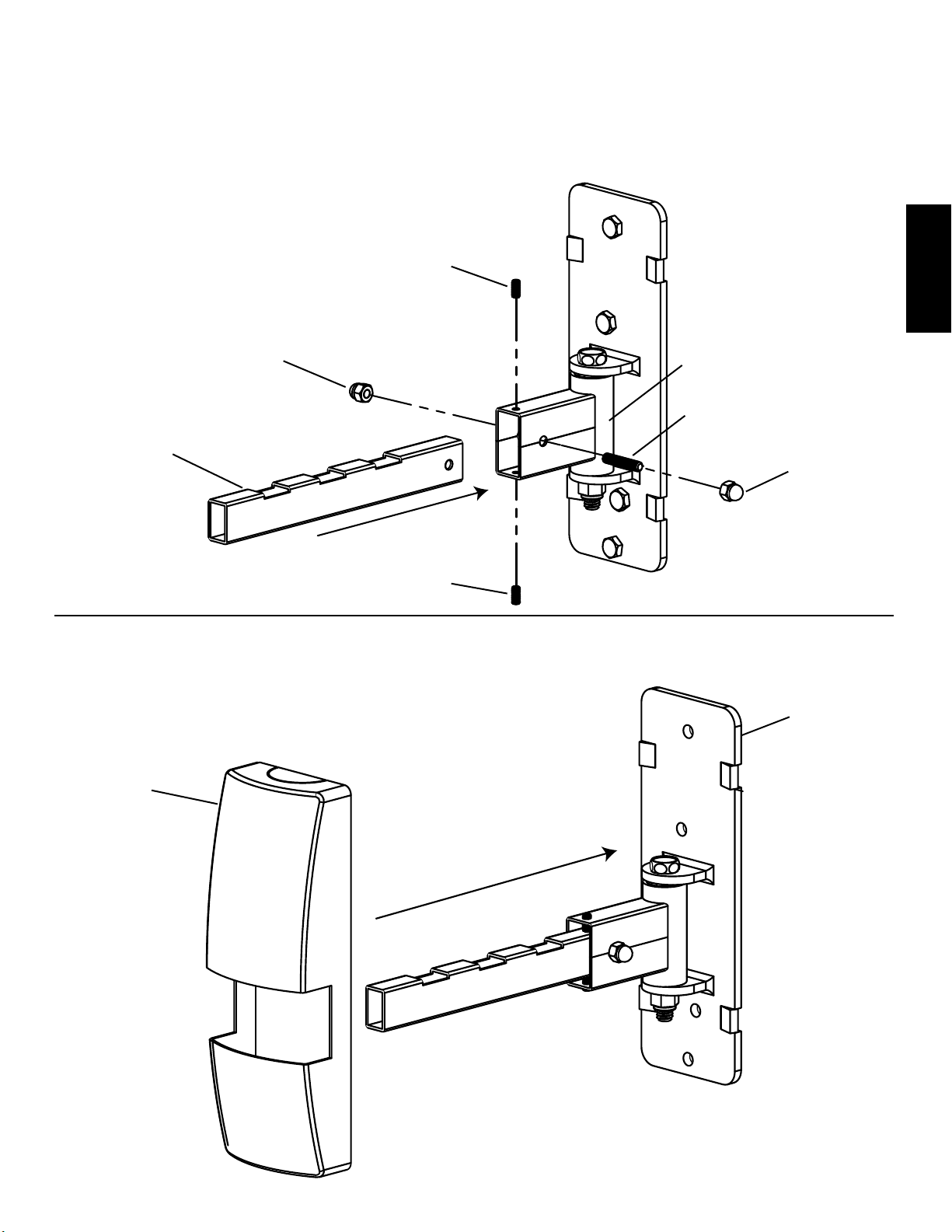
Step 3: Install Arm
Insert the Arm (f) into the Pivot (c) so the hole in the Arm aligns with the hole in the Pivot. Tighten one Acorn Nut (i) onto the Threaded
Stud (h). Insert the Threaded Stud through the holes in the Pivot and Arm. Attach the other Acorn Nut on the Threaded Stud. Firmly
tighten each Acorn Nut with the appropriate socket. Thread a Long Set Screw (l) through the hole in the top and bottom of the Pivot.
The Long Set Screws control the tilt of the Arm. Tighten with Allen Key (o) until the Arm has desired tilt angle. See Diagram 3 for
assistance.
Diagram 3
l
i c
h
f
i
ENGLISH
l
Step 4: Add Cover
Slide the Cover (b) so it clips onto the Wall Plate (a). See Diagram 4 for assistance.
a
Diagram 4
b
Page 6
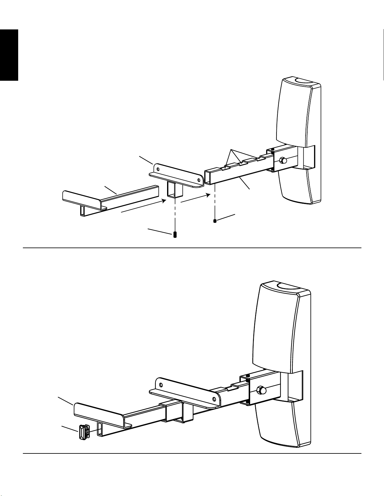
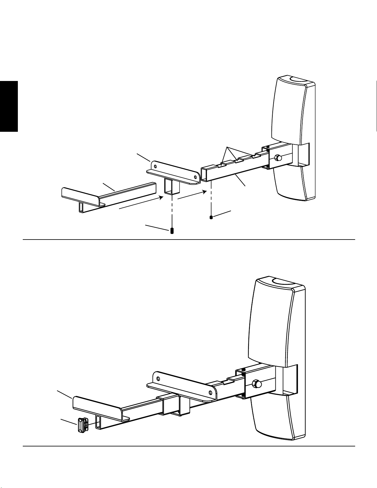
Step 5: Add Foot and Extension
Slide the Foot (d) over the Arm (f) until it fits into one of the three slots in the Arm. Slide the Extension (e) into the Arm. Adjust the Foot
and Extension until the speaker is a snug fit. Once you have them in the desired positions, thread a Long Set Screw (l) into the Foot and
tighten firmly with the Allen Key (o). Thread a Short Set Screw (m) into the Arm and tighten it with the Allen Key until the Extension is
secure. See Diagram 5 for assistance.
ENGLISH
Note: Do not leave speaker on
mount unattended unless all
set screws are in place!
slot
d
e
f
Diagram 5
m
l
Step 6: Add Cap
Press fit the Cap (n) into the Extension (e). See Diagram 6 for assistance.
Diagram 6
e
n
Sanus Systems 2221 Hwy 36 West, Saint Paul, MN 55113 USA
Customer Service: 800.359.5520. See complementary Sanus products at www.sanus.com
Page 7
Instrucciones de ensamblaje del modelo: WMS2
Gracias por elegir el modelo WMS2 de Sanus Systems. El modelo WMS2 está diseñado para sostener un parlante de estante de libros
de hasta 12" (30,5 cm) de profundidad y un peso de 15 lb (6,8 kg).
Advertencia de seguridad: Si no entiende estas instrucciones o si tiene alguna duda con respecto a la seguridad de la instalación, llame
a un contratista cualificado o comuníquese con Sanus llamando al 800.359.5520 (en EE.UU.) o al 31 (0) 40 2668619 (en Europa). Puede
también visitar nuestro sitio web en www.sanus.com. Revise cuidadosamente los productos para asegurarse de que ninguna pieza falte ni
presente defectos. Nuestros representantes del servicio de atención al cliente le ofrecerán asistencia inmediata con cualquier duda sobre la
instalación o con respecto a piezas faltantes o dañadas. Las piezas de repuesto para los productos comprados a través de un distribuidor
autorizado se enviarán directamente a usted. Nunca use piezas defectuosas. La instalación incorrecta podría ocasionar daños o lesiones
graves. No utilice este producto para fines no explícitamente especificados por Sanus Systems. Sanus Systems no será responsable por daños
ni lesiones debidos al montaje, ensamblaje o uso incorrectos. Llame a Sanus Systems antes de devolver los productos al punto de compra.
Herramientas necesarias: Taladro, broca de 3/16" (0,5 cm) y un juego de casquillos
Piezas y tornillería suministradas: Algunas piezas no se muestran en tamaño real*
(2) Pivote - c* (2) Pata - d*
ESPAÑOL
(2) Placa para pared - a* (2) Cubierta - b* (2) Extensión - e* (2) Brazo - f*
(8) Tirafondo - g (2) Vástago roscado - h (4) Tuerca ciega - i
(2) Perno de pivote - j (2) Tuerca de pivote - k (6) Tornillo prisionero largo - l
(2) Tornillo prisionero corto - m (1) Llave allen - o
(2) Tapa - n
Sanus Systems 2221 Hwy 36 West, Saint Paul, MN 55113 USA
Servicio de atención al cliente: 800.359.5520. Vea los productos complementarios de Sanus en el sitio www.sanus.com
Page 8
Paso 1: Conexión de la placa de pared
La placa de pared (a) se debe montar a un pie derecho de madera. Asegúrese de que la placa de pared quede orientada de manera que
el lado plano quede contra la pared y las dos pestañas lo más cerca a la parte inferior. Utilice la placa de pared como una plantilla para
marcar las 4 posiciones de los agujeros para los tirafondos (g) entre los dos bordes de la viga seleccionada. Perforar cuatro agujeros de
2,5" (6,4 cm) en los puntos marcados utilizando una broca de 3/16" (0,5 cm). Conecte la placa en la pared con los cuatro tirafondos.
Apriete los tirafondos con el casquillo apropiado. Vea el diagrama 1 como ayuda.
ADVERTENCIA: Apretar los tirafondos sólo hasta que la placa de pared quede bien asegurada contra la pared. ¡NO
APRETAR DEMASIADO LOS TIRAFONDOS!
Diagrama 1
a
g
ESPAÑOL
Paso 2: Instalación del pivote
Pase un perno de pivote (j) por la pestaña superior de la placa (a), el pivote (c), la pestaña inferior de la placa, y finalmente enrósquelo
en la tuerca de pivote (k). Apriete firmemente la tuerca de pivote con el casquillo apropiado. Vea el diagrama 2 como ayuda.
Diagrama 2
j
a
c
k
Page 9
Paso 3: Instalación del brazo
Inserte el brazo (f) en el pivote (c) de manera que el agujero del brazo se alinee con el agujero del pivote. Apriete una tuerca ciega (i)
en el vástago roscado (h). Inserte el vástago roscado por los agujeros en el pivote y el brazo. Conecte la otra tuerca ciega en el vástago
roscado. Apriete firmemente la tuerca ciega con el casquillo apropiado. Pase un tornillo prisionero largo (l) por los agujeros en las partes
superior e inferior del pivote. Los tornillos prisioneros largos controlan la inclinación del brazo. Apriete con una llave allen (o) hasta que
el brazo tenga el ángulo de inclinación deseado. Vea el diagrama 3 como ayuda.
Diagrama 3
l
i c
h
f
i
l
Paso 4: Instalación de la cubierta
ESPAÑOL
Deslice la cubierta (b) de manera que encaje en la placa de pared (a). Vea el diagrama 4 como ayuda.
a
Diagrama 4
b
Page 10
Paso 5: Instalación de pata y extensión
Deslice la pata (d) sobre el brazo (f) hasta que calce en una de las tres ranuras del brazo. Deslice la extensión (e) en el brazo. Ajuste la
pata y extensión hasta que el parlante calce de manera ceñida. Una vez que los tenga en las posiciones deseadas, enrosque un tornillo
prisionero largo (l) en la pata y apriete con una llave allen (o). Enrosque un tornillo prisionero corto (m) en el brazo y apriételo con la
llave allen hasta que la extensión quede bien asegurada. Vea el diagrama 5 como ayuda.
Diagrama 5
Nota: ¡No deje el parlante sobre
el soporte sin vigilancia, a menos que todos
los tornillos prisioneros estén instalados!
ESPAÑOL
ranura
d
e
f
m
l
Paso 6: Instalación de la tapa
Encaje a presión la tapa (n) en la extensión (e). Vea el diagrama 6 como ayuda.
Diagrama 6
e
n
Sanus Systems 2221 Hwy 36 West, Saint Paul, MN 55113 USA
Servicio de atención al cliente: 800.359.5520. Vea los productos complementarios de Sanus en el sitio www.sanus.com
Page 11
Montageanleitung für Modell: WMS2
Wir freuen uns, dass Sie sich für das Modell WMS2 von Sanus Systems entschieden haben. Die Halterung Modell WMS2 ist für
Regallautsprecher mit einer Tiefe von maximal 12" (30,5 cm) und einem Gewicht von 15 US-Pfund (6,8 kg) geeignet.
Sicherheitshinweis: Wenn Sie diese Anweisungen nicht verstehen oder Zweifel an der Sicherheit der Montage haben, rufen Sie einen
Fachmann an oder wenden Sie sich telefonisch an Sanus Systems unter +1-800-359-5520 (USA) oder +31-(0)40-266-8619 (Europa). Sie
können auch unsere Website besuchen: www.sanus.com. Prüfen Sie sorgfältig, ob Teile fehlen oder defekt sind. Unsere Kundendienstmitarbeiter
können Ihnen bei Fragen zur Montage und bei fehlenden oder beschädigten Teilen schnell weiterhelfen. Ersatzteile für bei autorisierten
Fachhändlern gekaufte Sanus-Produkte werden direkt an Ihre Adresse versendet. Verwenden Sie niemals beschädigte Teile! Unsachgemäße
Montage kann Schäden am Gerät und schwere Verletzungen hervorrufen. Verwenden Sie das Produkt nicht für andere als von Sanus Systems
explizit genannte Zwecke. Sanus Systems haftet nicht für Schäden oder Verletzungen, die durch unsachgemäße Montage, fehlerhaften
Zusammenbau oder unsachgemäße Nutzung entstehen. Bitte rufen Sie Sanus Systems an, bevor Sie Produkte beim Händler reklamieren.
Erforderliche Werkzeuge: Bohrmaschine, Bohrer 3/16" (0,5 cm) und Steckschlüsselsatz
Mitgelieferte Teile und Zubehör: Einige Teile sind nicht in Originalgröße abgebildet*
(2) Drehgelenk - c* (2) Fuß - d*
DEUTSCH
(2) Wandplatte – a* (2) Abdeckung – b* (2) Verlängerung - e* (2) Arm - f*
(8) Holzschraube - g (2) Gewindebolzen - h (4) Hutmutter - i
(2) Gelenkzapfen - j (2) Gelenkmutter - k (6) Lange Einstellschraube - l
(2) Kurze Einstellschraube - m (1) Inbusschlüssel - o
(2) Kappe - n
Sanus Systems 2221 Hwy 36 West, Saint Paul, MN 55113 USA
Kundendienst: 800.359.5520. Ergänzende Sanus-Produkte finden Sie unter www.sanus.com.
Page 12

Schritt 1: Montage der Wandplatte
Die Wandplatte (a) muss an einem Holzbalkenträger montiert werden. Die Wandplatte muss mit der flachen Seite zur Wand zeigen und
die beiden Nasen müssen sich dichter an der Unterseite befinden. Die Wandplatte als Schablone zur Markierung der 4 Montagebohrungen
für die Holzschrauben (g) zwischen den beiden Kanten des gefundenen Holzbalkenträgers verwenden. An den markierten Stellen vier
Bohrungen mit einer Tiefe von 2,5" (6,4 cm) mit einem Bohrer 3/16" (0,5 cm) vorbohren. Die Wandplatte mit den vier Holzschrauben
an der Wand montieren. Jede Holzschraube mit einem passenden Steckschlüssel festziehen. Siehe Abbildung 1.
VORSICHT: Die Holzschrauben nur so weit festziehen, dass die Wandplatte fest gegen die Wand drückt. DIE
HOLZSCHRAUBEN NICHT ÜBERDREHEN!
Abbildung 1
a
g
DEUTSCH
Schritt 2: Drehgelenk installieren
Einen Gelenkzapfen (j) durch die obere Nase in der Wandplatte (a), das Drehgelenk (c), die untere Nase in der Wandplatte führen und
schließlich in die Gelenkmutter (k) eindrehen. Die Gelenkmutter mit dem geeigneten Steckschlüssel festziehen. Siehe Abbildung 2.
Abbildung 2
j
a
c
k
Page 13

Schritt 3: Arm anbringen
Den Arm (f) in das Drehgelenk (c) einführen, so dass die Bohrung im Arm direkt über der Bohrung im Drehgelenk liegt. Eine Hutmutter (i)
den Gewindebolzen (h) drehen und fest anziehen. Den Gewindebolzen durch die Bohrungen im Drehgelenk und Arm stecken. Die andere
Hutmutter am Gewindebolzen befestigen. Jede Hutmutter mit dem geeigneten Steckschlüssel festziehen. Eine lange Einstellschraube (l)
durch die Bohrung an der Ober- und Unterseite des Drehgelenks eindrehen. Mit den langen Einstellschrauben wird die Neigung des Arms
gesteuert. Mit einem Inbusschlüssel (o) festziehen, bis der Arm den gewünschten Neigungswinkel erreicht hat. Siehe Abbildung 3.
Abbildung 3
l
i c
h
f
i
auf
DEUTSCH
l
Schritt 4: Abdeckung anbringen
Die Abdeckung (b) so verschieben, dass sie auf der Wandplatte (a) einrastet. Siehe Abbildung 4.
a
Abbildung 4
b
Page 14

Schritt 5: Fuß und Verlängerung anbringen
Den Fuß (d) über den Arm (f) schieben, bis er in einen der drei Schlitze im Arm passt. Die Verlängerung (e) in den Arm hineinschieben.
Den Fuß und die Verlängerung so anpassen, dass der Lautsprecher fest sitzt. Nachdem alle Teile korrekt positioniert sind, eine lange
Einstellschraube (l) in den Fuß eindrehen und mit dem Inbusschlüssel (o) fest anziehen. Eine kurze Einstellschraube (m) in den Arm
eindrehen und mit dem Inbusschlüssel fest anziehen, so dass die Verlängerung fest montiert ist. Siehe Abbildung 5.
Abbildung 5
Hinweis: Den Lautsprecher an der
Halterung erst dann loslassen, wenn alle
Einstellschrauben fest angezogen sind!
Schlitz
d
DEUTSCH
e
f
m
l
Schritt 6: Kappe anbringen
Die Verlängerung (e) mit der Kappe (n) verschließen. Weitere Hinweise siehe Abbildung 6.
Abbildung 6
e
n
Sanus Systems 2221 Hwy 36 West, Saint Paul, MN 55113 USA
Kundendienst: 800.359.5520. Ergänzende Sanus-Produkte finden Sie unter www.sanus.com.
Page 15

Instructions de montage pour le modèle : WMS2
Nous vous remercions d’avoir choisi le modèle WMS2 de Sanus Systems. Le modèle WMS2 est conçu pour soutenir une enceinte
d’étagère d’une profondeur maximale de 12" (30,5 cm) et d’un poids de 15 lb (6,8 kg).
Avertissements relatifs à la sécurité : si vous ne comprenez pas ces instructions ou si vous avez un doute quant à la sécurité
de cette installation, veuillez faire appel à un technicien qualifié ou communiquez avec Sanus en composant le 1-800-359-5520
(aux États-Unis) ou le 31 (0) 40 2668619 (pour l’Europe). Vous pouvez également visiter notre site web au www.sanus.com. Vérifiez
soigneusement qu’aucune pièce n’est manquante ou défectueuse. Les représentants de notre service à la clientèle peuvent répondre
rapidement à toute question concernant l’installation ou des pièces manquantes ou endommagées. Les pièces de rechange de produits
achetés auprès de distributeurs agréés vous seront livrées directement. N’utilisez jamais de pièces défectueuses. Une installation incorrecte
peut entraîner des dommages ou des blessures graves. Ce produit ne doit être utilisé que pour des usages explicitement spécifiés par
Sanus Systems. Sanus Systems ne pourra être tenu responsable de dommages ou de blessures dus à un montage incorrect, un assemblage
incorrect ou un usage incorrect. Veuillez contacter Sanus Systems avant de renvoyer des produits au point de vente.
Outils nécessaires : perceuse, mèche de 3/16" (0,5 cm) et jeu de douilles
Pièces et matériel fournis : certaines pièces ne sont pas illustrées grandeur réelle*
(2) Articulation - c* (2) Pied - d*
(2) Plaque murale - a* (2) Couvercle - b* (2) Extension - e* (2) Bras - f*
(8) Tire-fond - g (2) Tige filetée - h (4) Écrou borgne - i
FRANÇAIS
(2) Boulon d’articulation - j (2) Écrou d’articulation - k (6) Vis de pression longue - l
(2) Vis de pression courte - m (1) Clé Allen - o
(2) Capuchon - n
Sanus Systems 2221 Hwy 36 West, Saint Paul, MN 55113 USA
Service à la clientèle : 800.359.5520. Pour les produits Sanus complémentaires, visitez le site www.sanus.com
Page 16

Étape 1 : Fixation de la plaque murale
La plaque murale (a) doit être montée sur une ossature en bois. Veillez à orienter la plaque murale de façon que la surface plate soit
contre le mur et les deux pattes du côté inférieur. Servez-vous de la plaque murale comme gabarit pour marquer l’emplacement de quatre
trous pour les tire-fond (g) entre les deux rebords du montant choisi. Percez quatre avant-trous de 2,5" (6,4 cm) de profondeur à l’aide
d’une mèche de 3/16" (0,5 cm) aux emplacements indiqués. Fixez la plaque murale au mur à l’aide des quatre tire-fond. Serrez tous les
tire-fond en utilisant la douille appropriée. Reportez-vous au schéma 1 si nécessaire.
AVERTISSEMENT : Serrez les tire-fond jusqu’à ce que la plaque murale soit tirée fermement contre le mur.
NE SERREZ PAS EXCESSIVEMENT LES TIRE-FOND !
Schéma 1
a
g
FRANÇAIS
Étape 2 : Installation de l’articulation
Introduisez un boulon d’articulation (j) par le haut dans la patte supérieure de la plaque murale (a), dans l’articulation (c), dans la patte
inférieure de la plaque murale, puis vissez-le dans l’écrou d’articulation (k). Serrez fermement l’écrou d’articulation à l’aide de la douille
appropriée. Reportez-vous au schéma 2 si nécessaire.
Schéma 2
j
a
c
k
Page 17

Étape 3 : Installation du bras
Introduisez le bras (f) dans l’articulation (c) de manière que le trou du bras s’aligne sur le trou de l’articulation. Serrez un écrou borgne (i)
sur la tige filetée (h). Insérez la tige filetée dans les trous de l’articulation et du bras. Fixez l’autre écrou borgne sur la tige filetée. Serrez
fermement chaque écrou borgne à l’aide de la douille appropriée. Enfilez une vis de pression longue (l) dans le trou en haut et en bas de
l’articulation. Les vis de pression longues contrôlent l’inclinaison du bras. Serrez avec la clé Allen Key (o) jusqu’à ce que le bras soit à
l’angle d’inclinaison désiré. Reportez-vous au schéma 3 si nécessaire.
Schéma 3
l
i c
h
f
i
FRANÇAIS
l
Étape 4 : Pose du couvercle
Glissez le couvercle (b) de manière à ce qu’il s’enclenche sur la plaque murale (a). Reportez-vous au schéma 4 si nécessaire.
a
Schéma 4
b
Page 18

Étape 5 : Pose du pied et de l’extension
Enfilez le pied (d) sur le bras (f) de manière à l’emboîter dans une des trois fentes du bras. Introduisez l’extension (e) dans le bras.
Ajustez le pied et l’extension de manière à ce que l’enceinte soit serrée et bien retenue. Lorsqu’ils se trouvent aux positions désirées,
enfilez une vis de pression longue (l) dans le pied et serrez-la fermement à l’aide de la clé Allen (o). Enfilez une vis de pression courte
(m) dans le bras et serrez-la fermement à l’aide de la clé Allen jusqu’à ce que l’extension soit solidement fixée. Reportez-vous au schéma
5 si nécessaire.
Schéma 5
Remarque : ne laissez pas l’enceinte sans
surveillance sur la monture tant que les
vis de pression n’ont pas été installées !
fente
d
e
f
m
l
FRANÇAIS
Étape 6 : Pose du capuchon
Enfoncez le capuchon (n) dans l’extension (e). Reportez-vous au schéma 6 si nécessaire.
Schéma 6
e
n
Sanus Systems 2221 Hwy 36 West, Saint Paul, MN 55113 USA
Service à la clientèle : 800.359.5520. Pour les produits Sanus complémentaires, visitez le site www.sanus.com
Page 19

Istruzioni di montaggio per il modello WMS2
Grazie per aver scelto un prodotto Sanus Systems WMS2. Il WMS2 è progettato per sostenere un altoparlante profondo fino a 12"
[30,5 cm] e con un peso massimo di 15 lb [6,8 kg].
Avvertenza sulla sicurezza: se queste istruzioni risultano poco chiare o si hanno dubbi sulla sicurezza dell’installazione, rivolgersi
a un installatore specializzato o contattare Sanus al numero verde USA 800.359.5520 o, in Europa, al numero +31 (0) 40 2668619.
È anche possibile visitare il sito www.sanus.com. Controllare attentamente che non vi siano parti mancanti o difettose. Il servizio Sanus
di assistenza clienti risponde rapidamente a domande sull’installazione e sulle parti mancanti o danneggiate. Le parti di ricambio per
prodotti acquistati attraverso i rivenditori autorizzati vengono spedite direttamente al cliente. Non utilizzare parti difettose. L’installazione
errata può causare danni o lesioni gravi. Non utilizzare questo prodotto per scopi diversi da quelli specificamente indicati da Sanus
Systems. Sanus Systems non è responsabile di danni o lesioni causati da montaggio o utilizzo non corretti. Chiamare Sanus Systems
prima di riportare i prodotti al punto vendita.
Strumenti necessari: trapano con punta da 3/16" [0,5 cm] e un set di chiavi esagonali
Parti e minuteria metallica fornite: alcune parti mostrate non sono mostrate nelle dimensioni reali*
(2) perni di articolazione - c* (2) piedi - d*
(2) piastre per parete - a* (2) coperchi - b* (2) estensioni - e* (2) bracci - f*
(8) tirafondo - g (2) perni filettati - h (4) dadi ciechi - i
(2) bulloni pivottanti - j (2) dadi pivottanti - k (6) controviti lunghe - l
ITALIANO
(2) controviti corte - m (1) chiave a brugola - o
(2) tappi - n
Sanus Systems 2221 Hwy 36 West, Saint Paul, MN 55113 USA
Assistenza clienti: 800.359.5520. Vedere i prodotti complementari Sanus sul sito www.sanus.com
Page 20

Fase 1: Installazione della piastra per parete
La piastra per parete (a) deve essere montata in corrispondenza di una trave di sostegno, in caso di pareti a pannelli. Assicurarsi che
la piastra per parete sia orientata in modo che la superficie piatta si trovi contro la parete e le linguette si trovino verso il fondo. Utilizzare
la piastra per parete come maschera per contrassegnare la posizione di 4 fori per i tirafondo (g) tra i due bordi del perno prescelto. Nelle
posizioni segnate, praticare quattro fori profondi 2,5" [6,4 cm] utilizzando una punta per trapano da 3/16" [0,5 cm]. Fissare la piastra alla
parete usando tutti i quattro tirafondo. Serrare ogni tirafondo con la chiave appropriata (vedere la figura 1).
AVVERTENZA: serrare i tirafondo solo no a che la piastra per parete non è ben ssata alla parete. NON SERRARE
ECCESSIVAMENTE I TIRAFONDO.
a
g
Figura 1
Fase 2: Installazione del perno di articolazione
Inserire un bullone pivottante (j) attraverso la linguetta superiore della piastra per parete (a), il perno di articolazione (c), la linguetta
inferiore della piastra per parete ed infine avvitarlo nel dado pivottante (k). Serrare bene il dado pivottante con la chiave appropriata
ITALIANO
(vedere la figura 2).
Figura 2
j
a
c
k
Page 21

Fase 3: Installazione del braccio
Inserire il braccio (f) nel perno di articolazione (c) in modo che il foro nel braccio sia allineato al foro nel perno. Serrare un dado cieco
(i) sul perno filettato (h). Inserire il perno filettato nei fori nel perno di articolazione e nel braccio. Fissare l’altro dado cieco sul perno
filettato. Serrare bene entrambi i dadi ciechi con la chiave appropriata. Inserire una controvite lunga (l) attraverso il foro nella parte
superiore e inferiore del perno di articolazione. Le controviti lunghe servono a regolare l’inclinazione del braccio. Avvitare con la chiave
a brugola (o) finché non si ottiene l’inclinazione desiderata (vedere la figura 3).
Figura 3
l
i c
h
f
i
l
Fase 4: Installazione del coperchio
Far scorrere il coperchio (b) in modo che si agganci alla piastra per parete (a) (vedere la figura 4).
a
Figura 4
b
ITALIANO
Page 22

Fase 5: Installazione del piede e dell’estensione
Far scorrere il piede (d) sul braccio (f) finché non si inserisce in una delle fessure del braccio. Far scorrere l’estensione (e) nel braccio.
Regolare il piede e l’estensione finché l’altoparlante non è montato correttamente. Una volta ottenuta la posizione desiderata, avvitare
una controvite lunga (l) nel piede e serrare bene con la chiave a brugola (o). Avvitare una controvite corta (m) nel braccio e serrarla con
la chiave a brugola finché l’estensione non è ben fissata (vedere la figura 5).
Figura 5
Nota: non lasciare senza sostegno
l’altoparlante sul montaggio nché tutte
le controviti non sono in posizione.
fessura
d
e
f
m
l
Fase 6: Installazione del tappo
Spingere il tappo (n) nell’estensione (e) (vedere la figura 6).
ITALIANO
e
Figura 6
n
Assistenza clienti: 800.359.5520. Vedere i prodotti complementari Sanus sul sito www.sanus.com
Sanus Systems 2221 Hwy 36 West, Saint Paul, MN 55113 USA
Page 23

Инструкция по сборке крепления модели WMS2
Благодарим Вас за приобретение крепления WMS2 компании Sanus Systems. Крепление WMS2 предназначено для установки полочной
акустической колонки толщиной до 12" (30,5 см) и весом до 15 фунтов (6,8 кг).
Внимание! Если Вам непонятны приведенные ниже инструкции, или у Вас есть какие-либо сомнения по поводу безопасности использования
установленного устройства, обратитесь к квалифицированному специалисту или в компанию Sanus по телефону 800.359.5520 (США)
или 31 (0)40 2668619 (Европа). Вы также можете посетить наш веб-сайт www.sanus.com. Тщательно проверьте наличие всех деталей и
отсутствие заводского брака. Сотрудники нашей службы работы с покупателями незамедлительно помогут Вам решить все вопросы,
связанные с установкой устройства, а также с недостающими либо поврежденными деталями. Запасные части к изделиям компании Sanus,
приобретенным через уполномоченных агентов по продаже, будут доставлены непосредственно по указанному Вами адресу. Не используйте
бракованные детали. Неправильная установка устройства может привести к травмированию людей и порче имущества. Это изделие может
применяться исключительно в целях, указанных производителем. Компания Sanus Systems не несет ответственности за вред здоровью
или материальный ущерб, причиненный вследствие неправильной сборки, монтажа и эксплуатации устройства. Решив вернуть изделие в
магазин, где Вы его приобрели, обратитесь, пожалуйста, сначала в компанию Sanus Systems.
Необходимые инструменты: дрель, сверло 3/16" (0,5 см), набор торцовых насадок
Детали устройства и крепежные детали: некоторые детали изображены в масштабе*
Кронштейн поворотный (c)* – 2 шт. Опора (d)* – 2 шт.
Пластина крепежная настенная (a)* – 2 шт. Крышка (b)* – 2 шт. Удлинитель (e)* – 2 шт. Консоль (f)* - 2 шт.
Шуруп под ключ (g) – 8 шт. Шпилька резьбовая (h) - 2 шт. Гайка колпачковая (i) - 4 шт.
Болт шарнирный (j) – 2 шт. Гайка регулирующая (k) - 2 шт. Винт стопорный длинный (l) - 6 шт.
Русский
Винт стопорный короткий (m) - 2 шт. Ключ шестигранный (o) – 1 шт.
Колпачок (n) – 2 шт.
Sanus Systems 2221 Hwy 36 West, Saint Paul, MN 55113 USA
Служба работы с покупателями: 800.359.5520. См. дополнительные изделия производства Sanus на веб-сайте www.sanus.
com
Page 24

Шаг 1. Установка настенной крепежной пластины
Крепежная пластина (a) должна устанавливаться на деревянной стойке каркасной стены. Плоская поверхность крепежной
пластины должна быть направлена к стене, а две ее петли должны располагаться ближе к нижнему краю. Воспользовавшись настенной
крепежной пластиной как шаблоном, отметьте места для 4 отверстий под шурупы (g) между краями выбранной стойки. С помощью
сверла диаметром 3/16 дюйма (0,5 см) просверлите четыре черновых отверстия глубиной 2,5 дюйма (6,4 см). Четырьмя шурупами под
ключ закрепите настенную пластину на стене. Затяните каждый шуруп с помощью соответствующей торцовой насадки. См. рисунок 1.
ВНИМАНИЕ! Затяните шурупы так, чтобы пластина плотно прижалась к стене. НЕ ЗАТЯГИВАЙТЕ ШУРУПЫ ЧРЕЗМЕРНО СИЛЬНО!
Рисунок 1
a
g
Шаг 2. Установка поворотного кронштейна
Вставьте шарнирный болт (j) сверху в верхнюю петлю настенной пластины (a), в кронштейн (c), в нижнюю петлю настенной пластины и навинтите
на него регулирующую гайку (k). Туго затяните регулирующую гайку с помощью соответствующей торцовой насадки. См. рисунок 2.
Рисунок 2
j
Русский
a
c
k
Page 25

Шаг 3. Установка консоли
Вставьте консоль (f) в поворотный кронштейн (c) и совместите отверстие в консоли с отверстием в поворотном кронштейне. Навинтите и
затяните одну колпачковую гайку (i) на резьбовую шпильку (h). Вставьте свободный конец резьбовой шпильки в отверстия в кронштейне и
консоли. Навинтите на резьбовую шпильку вторую колпачковую гайку. Туго затяните обе колпачковые гайки с помощью соответствующей
торцовой насадки. Завинтите в верхнее и нижнее отверстия поворотного кронштейна длинные стопорные винты (l). Длинные стопорные
винты позволяют регулировать наклон консоли. Регулировкой длинных стопорных винтов выберите нужный угол наклона консоли и
затяните стопорные винты шестигранным ключом (o). См. рисунок 3.
Рисунок 3
l
i c
h
f
i
l
Шаг 4. Установка крышки
Приставьте крышку (b) к настенной пластине (a) и прижмите. Вы должны услышать щелчок.
См. рисунок 4. a
Рисунок 4
b
Русский
Page 26

Шаг 5. Установка опоры и удлинителя
Установите опору (d) на консоль (f) и совместите с одной из трех прорезей в консоли. Вставьте удлинитель (e) в консоль. Отрегулируйте
опору и удлинитель для плотной посадки акустической колонки. Отрегулировав опору и удлинитель, завинтите в опору длинный стопорный
винт (l) и плотно затяните его шестигранным ключом (o). Завинтите в консоль короткий стопорный винт (m) и, затянув его шестигранным
ключом, надежно зафиксируйте удлинитель. См. рисунок 5.
Рисунок 5
Примечание. Не оставляйте колонку на
креплении без присмотра, с неустановленными
на место стопорными винтами!
прорезь
d
e
f
m
l
Шаг 6. Установка колпачка
Вставьте колпачок (n) в удлинитель (e) и плотно прижмите. См. рисунок 6.
Рисунок 6
Русский
e
n
Sanus Systems 2221 Hwy 36 West, Saint Paul, MN 55113 USA
Служба работы с покупателями: 800.359.5520. См. дополнительные изделия производства Sanus на веб-сайте www.sanus.com
Page 27

モデルの組み立て説明書: WMS2
Sanus Systems WMS2をお買い上げいただきありがとうございます。WMS2 は奥行き12インチ[30.5 cm] 、重さ 15 ポンド
[6.8 kg] までのブックシェルフ型スピーカー用に設計されています。
安全性に関する警告: ここに記載されている説明ではよくわからない場合、もしくは取り付け上の安全性に疑問がある場合は、
有資格の契約業者にお電話いただくか、Sanus (米国: 800-359-5520 もしくは、ヨーロッパ: 31-(0)-40-2668619) までご連絡
ください。また、弊社のウェブサイト www.sanus.com もご参照ください。不足あるいは破損している部品がないか注意深く確認
してください。弊社のカスタマーサービス担当者が、設置に関するご質問または部品の不足や損傷について迅速に対応させていた
だきます。指定販売店でお求めいただいた製品については、交換部品をお客様に直接お届けいたします。破損した部品は絶対に使
用しないでください。設置方法が不適切な場合、破損や深刻なケガを引き起こすおそれがあります。Sanus Systems が明記してい
る目的以外でこの製品を使用しないでください。Sanus Systems は、取り付け、組立、使用が正しく行われていないことに起因する
破損、ケガについては責任を負いかねます。製品をご購入された販売店に返品する前に Sanus Systems までご連絡ください。
必要な工具:ドリル、3/16 インチ(0.5 cm)のドリルビット、ソケットセット
同梱部品および金具:実サイズと異なる大きさで表示されている 部品があります*
(2) ピボット - c* (2) 脚 - d*
(2) 壁面プレート - a* (2) カバー - b* (2) 拡張部品 - e* (2) アーム - f*
(8) ラグボルト - g (2) ネジ付き止め具 - h (4) エイコーン ナット - i
(2) ピボットボルト - j (2) ピボットナット - k (6) 長い止めネジ - l
(2) 短い止めネジ - m (1) アレンキー - o
(2) キャップ - n
Sanus Systems 2221 Hwy 36 West, Saint Paul, MN 55113 USA
カスタマーサービス:800.359.5520. その他の Sanus 製品については www.sanus.com をご覧ください
Page 28

手順 1:壁面プレートを取り付ける
壁面プレート (a) は、必ず木製の間柱に取り付けてください。平たい側を壁側に向け、二つのタブを下にして壁面プレートを取り
付けてください。壁面プレートを 型板として、選んだ間柱の両端の内側に、ラグボルト(g)のための四つの穴の位置に印を入れ、
3/16 インチ[0.5cm]のドリルビットを使って、印を付けた位置に予め奥行き 2.5インチ[6.4 cm] の穴を開けておきます。四つの
ラグボルトの全部を使って壁面プレートを壁に取り付けてください。次にソケットヘッドを使ってラグボルトを締めてください。詳し
くは、図 1 をご覧ください。
警告:ラグボルトは、壁面プレート が壁に密着する程度に締めつけます。ラグボルトを締めすぎないようにしてください!
図 1
a
g
手順 2:ピボットの取付け
壁面プレート(a)の上のタブ、ピボット(c)、下のタブを通して、ピボット ボルト(j)を差し込み、ピボット ナット(k)をねじ込みます。
適切なソケットを使ってピボット ナットを固く締めてください。詳しくは、図 2 をご覧ください。
図 2
j
a
c
k
Page 29

手順 3:アームの取付け
アームの穴とピボットの穴が揃うように、アーム(f)をピボット(c)へ差込みます。一つのエイコーンナット
(i)をネジ付き止め具(h)にねじ込みます。ピボットとアームの穴にネジ付き止め具を差込みます。もうひとつの
エイコーン ナットをネジ付き止め具に取り付けます。適したソケットを使ってそれぞれのエイコーンナットを
固く締めてください。長いほうの止めネジ(l)をピボットの上と下の穴に通します。長いほうの止めネジはアーム
の傾きを調節します。アレンキー(o)で止めネジを締め、アームが適切な角度になるよう調節してください。詳
しくは、図 3 をご覧ください。
図 3
l
i c
h
f
i
l
手順 4:カバーを付ける
カバー (b) をスライドさせ、壁面プレート (a) にはめ込みます。詳しくは、図 4 をご覧
ください。 a
図 4
b
Page 30

手順 5:脚と拡張部品の取り付け
脚(d)をアーム(f)の三つのスロットのひとつにはまるまでスライドさせる。拡張部品 (e) をアームにスライドさせる。スピーカ
ー
がピッタリとはまるように脚と拡張部品を調節する。これらのポジションが決まったら、長い止めネジ(l)を脚にねじ込み、アレンキ
ー(o)
を使って固く締める。短い止めネジ(m)をアームにねじ込み、拡張部品がしっかりと固定するまでアレンキーを使って固く締める。
詳しくは、図 5 をご覧ください。
図 5
注意:止めネジを全部取り付けるまでは、
マウント上にスピーカーをそのまま放置しないこと。
スロット
d
e
f
m
l
手順 6:キャップの取付け
拡張部品 (e) にキャップ(n)を押してはめ込む。詳しくは、図 6 をご覧ください。
図 6
e
n
Sanus Systems 2221 Hwy 36 West, Saint Paul, MN 55113 USA
カスタマーサービス:800.359.5520. その他の Sanus 製品については www.sanus.com をご覧ください
Page 31

WMS2 型号装配说明
感谢您选用 Sanus Systems WMS2。WMS2 设计用于支撑 最高为 12" [30.5 cm] 且最重为 15lbs [6.5 kg] 的书架音箱。
安全警告:如果您不理解这些说明或对安装的安全性有任何疑问,请致电有资格的承包商或与 Sanus 联系,联系电话:
800.359.5520(美国)或 31 (0) 40 2668619(欧洲)。您还可访问我们的网站 www.sanus.com。请仔细检查以确保没
有缺少零件或存在缺陷零件。我们的客户服务代表会迅速为您的安装问题提供协助,以及解决零件缺少或缺陷的问题。通过
授权经销商所购产品的替换零件将直接送货上门。切勿使用有缺陷的零件。安装不正确可能会导致损坏或严重受伤。切勿将
本品用于 Sanus Systems 未明示的任何其它目的。Sanus Systems 对由于安装不正确、装配不正确或使用不当引起的
损坏或受伤不承担任何责任。退货至购买点前请先致电 Sanus Systems。
必需的工具:钻孔机、3/16" [0.5 cm] 钻头和套筒组
提供的零件和五金件:某些零件不是按实际尺寸显示*
(2) 枢轴 - c* (2) 支点 - d*
(2) 墙板 - a* (2) 封盖 - b* (2) 延伸臂 - e* (2) 臂 - f*
(8) 方头螺栓 - g (2) 螺杆 - h (4) 球面螺母 - i
(2) 枢轴螺栓 - j (2) 枢轴螺母 - k (6) 长定位螺丝 - l
(2) 短定位螺丝 - m (1) 内六角扳手 - o
(2) 帽盖 - n
Sanus Systems 2221 Hwy 36 West, Saint Paul, MN 55113 USA
客户服务:800.359.5520. 有关 Sanus 公司的其它产品,请登录公司网站 www.sanus.com
中文
Page 32

步骤 1:安装墙板
墙板 (a) 必须安装到木立筋上。请确保墙板的安装方向,以便使墙板的平面紧贴墙面,并使两个突起靠近底部。以墙板
为样板,在所选墙筋的两条边中间标出四个用于安装方头螺栓 (g) 的位置。预先用 3/16" [0.5 cm] 钻头在标记位置钻出
2.5" [6.4 cm] 深的孔。使用所有四个方头螺栓将墙板安装到墙上。然后使用相应的套筒板手头旋紧每个方头螺栓。参阅图 1
以获得帮助。
警告:旋紧方头螺栓直至墙板紧贴墙面。切勿将方头螺栓旋得过紧!
图 1
a
g
步骤 2:安装枢轴
将枢轴螺栓 (j) 向下穿过墙板 (a) 上的顶部突起、枢轴 (c) 和墙板中的下部突起,并最终旋入枢轴螺母 (k) 中。使用合适的套
筒旋紧枢轴螺母。参阅图 2 以获得帮助。
图 2
j
a
c
中文
k
Page 33

步骤 3:安装臂
将臂 (f) 插入枢轴 (c),使臂上的孔与枢轴中的孔对齐。将一个球面螺母 (i) 旋入螺杆 (h)。穿过枢轴和臂上的孔插入螺杆。将
另一个球面螺母安装到螺杆上。使用合适的套筒旋紧每个球面螺母。将长定位螺丝 (l) 穿过枢轴顶部和底部孔旋入。长定位
螺丝控制臂的倾斜度。使用内六角扳手 (o) 拧紧,直到臂达到所需倾斜角度。参阅图 3 以获得帮助。
图 3
l
i c
h
f
i
l
步骤 4:安装封盖
滑动封盖 (b) 直到封盖与墙板 (a) 完全密合。参阅图 4 以获得帮助。
a
图 4
b
中文
Page 34

步骤 5:安装支点和延伸臂
将支点 (d) 滑到臂 (f) 上直到装入臂上的三个槽中的一个。将延伸臂 (e) 滑入臂中。调整支点和延伸臂,直到音箱安装牢固。
音箱安装到所需位置之后,将长定位螺丝 (l) 旋入支点内并使用内六角扳手 (o) 旋紧。将短定位螺丝 (m) 旋入臂中,并使用内
六角扳手旋紧,直到固定好延伸臂。参阅图 5 以获得帮助。
图 5
注意:除非所有的定位螺丝安装到位,
否则不得放开
架上的音箱!
插槽
d
e
f
m
l
步骤 6:安装帽盖
将帽盖 (n) 压合到延伸臂 (e) 上。参阅图 6 以获得帮助。
图 6
e
n
中文
Sanus Systems 2221 Hwy 36 West, Saint Paul, MN 55113 USA
客户服务:800.359.5520. 有关 Sanus 公司的其它产品,请登录公司网站 www.sanus.com
 Loading...