

Page 1
ESPAÑOL
FRANÇAIS ITALIANO PYCCKO
ENGLISH
International Assembly Instructions for model VMPL3
Sanus Systems 2221 Hwy 36 West, Saint Paul, MN 55113 USA (6901-300039 <00>)
Customer Service Europe: 31 (0)20 5708938 • fax 31 (0)20 5708989
See complementary Sanus products at www.sanus.com
VMPL3_051106_ML.indd 1 7/17/06 11:36:48 AM
中文
Page 2

VMPL3_051106_ML.indd 2 7/17/06 11:36:49 AM
Page 3
ENGLISH
Assembly Instructions for Model: VMPL3
Thank you for choosing a Sanus Systems VisionMount™ Wall Mount. The VMPL3 is designed to hold 27” to 84” [686 mm to 2133 mm]
Flat Panel LCD or Plasma Displays weighing up to 280 lbs [127 kg].
CAUTION: The size and weight of your large screen television must not exceed 84” [2133 mm] diagonally and 280 Lbs [127.3
Kg], the maximum load capacity of the mount. Never use defective parts. Improper installation may cause property damage or
personal injury. Do not use this product for any purpose that is not explicitly specied by Sanus Systems.
If you do not understand these directions, or have any doubts about the safety of the installation, please call a qualied contractor
or contact Sanus at 800.359.5520 or www.sanus.com. Our customer service representatives can quickly assist you with installation
questions and missing or damaged parts. Replacement parts for products purchased through authorized dealers will be shipped directly
to you. Check carefully to make sure that there are no missing or defective parts. Sanus Systems can not be liable for damage or injury
caused by incorrect mounting, incorrect assembly, or incorrect use. Please call Sanus Systems before returning products to the point of
purchase.
NOTE: The supplied wall mounting hardware is not for metal stud or old cinder block walls. If you are uncertain about the nature
of your wall, consult an installation contractor. Sanus makes every effort to assure all necessary television mounting hardware
is included. If the hardware you need is not included please consult your local hardware store or call Sanus systems.
Required Tools: Drill, 3/16” bit (1/2” masonry bit for brick, concrete, or concrete block installations), wrench set, phillips screwdriver.
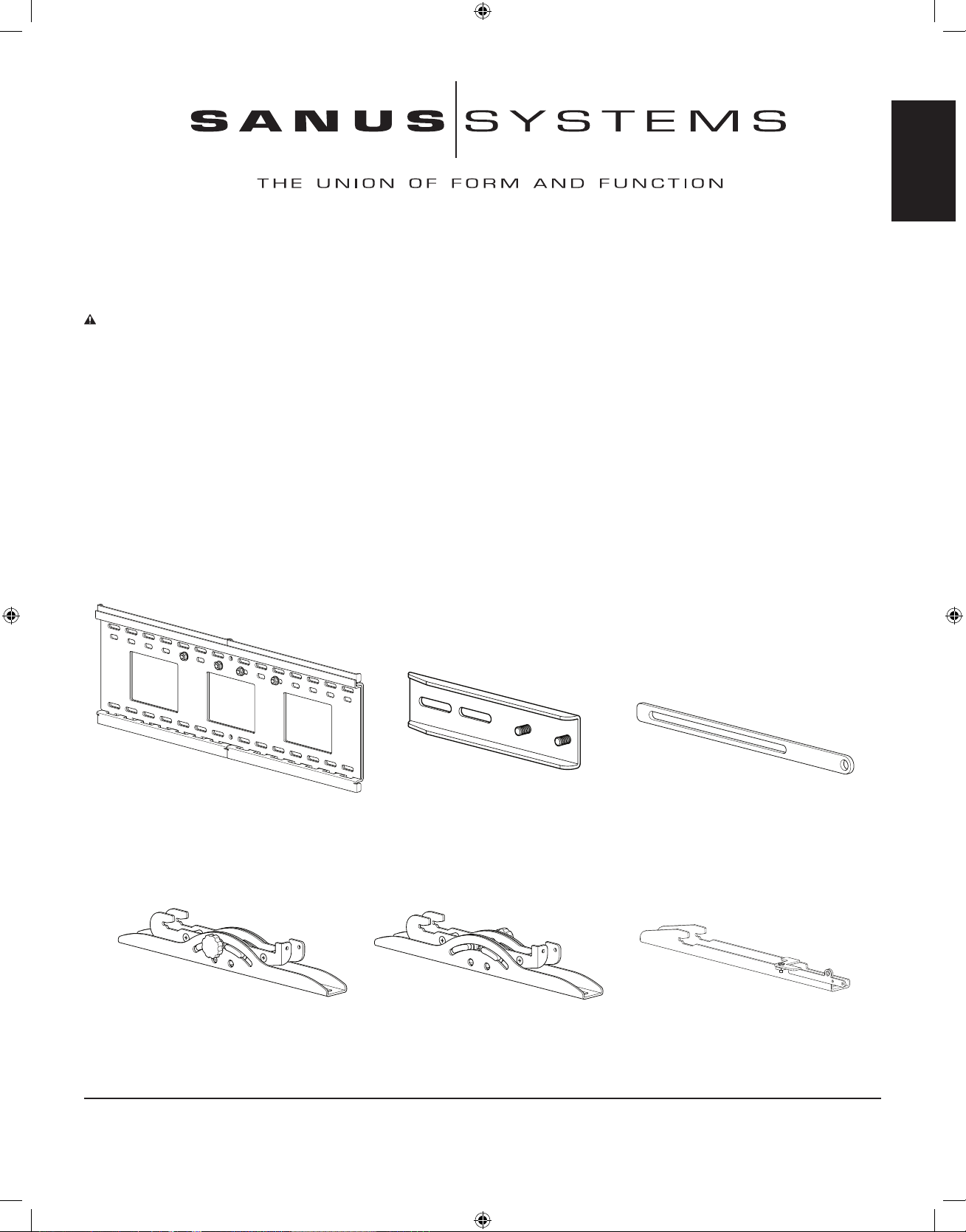
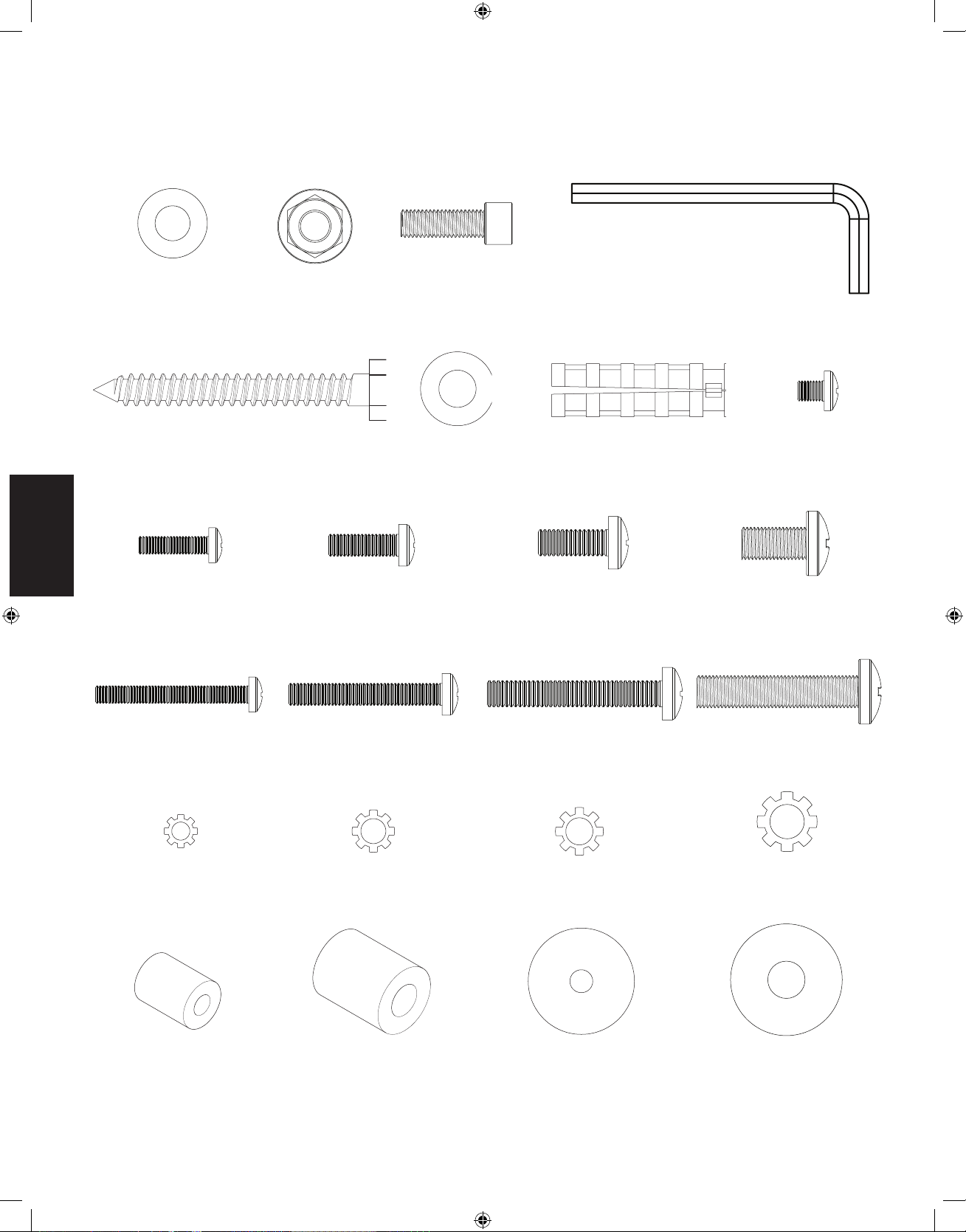
Supplied Parts and Hardware: (All threaded fasteners are shown full size.)
Wall Plate Assembly - A
Qty. 1
Monitor Bracket Extension - B
Qty. 4
Latch Extension - C
Qty. 2
Right Tilting Monitor Bracket - D
Qty. 1
Left Tilting Monitor Bracket - E
Qty. 1
Low Prole Monitor Bracket - F
Qty. 2
Sanus Systems 2221 Hwy 36 West, Saint Paul, MN 55113 USA
Customer Service: 800.359.5520. See complementary Sanus products at www.sanus.com
VMPL3_051106_ML.indd 3 7/17/06 11:36:52 AM
Page 4
ENGLISH
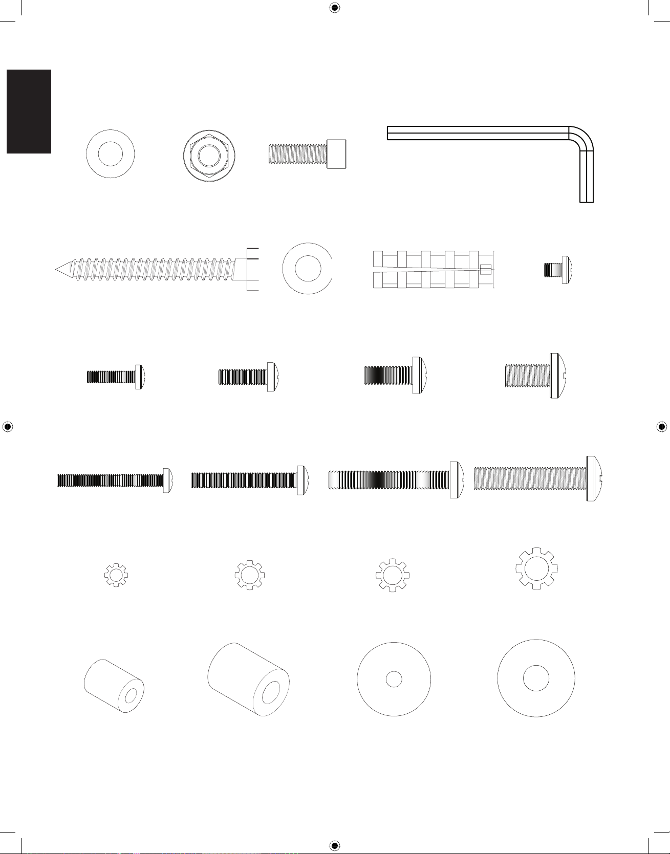
M4 x 16 mm Bolt - O
Qty. 4
M5 x 16 mm Bolt - P
Qty. 4
M6 x 16 mm Bolt - Q
Qty. 4
M8 x 16 mm Bolt - R
Qty. 4
M4 x 35 mm Bolt - S
Qty. 4
M5 x 35 mm Bolt - T
Qty. 4
M6 x 40 mm Bolt - U
Qty. 4
M8 x 40 mm Bolt - V
Qty. 4
M4 Lock Washer - W
Qty. 4
M5 Lock Washer - X
Qty. 4
M6 Lock Washer - Y
Qty. 4
M8 Lock Washer - Z
Qty. 4
M4/M5 Spacer - AA
Qty. 4
M6/M8 Spacer - BB
Qty. 4
M4/M5 Washer - CC
Qty. 8
M6/M8 Washer - DD
Qty. 4
Nylon Washer - G
Qty. 8
Flange Nut - H
Qty. 8
Safety Bolt - I
Qty. 2
Allen Key - J
Qty. 1
Lag Bolt - K
Qty. 6
Lag Bolt Washer - L
Qty. 6
Concrete Anchor - M
Qty. 6
10-32 Screw - N
Qty. 4
VMPL3_051106_ML.indd 4 7/17/06 11:37:02 AM
Page 5
ENGLISH
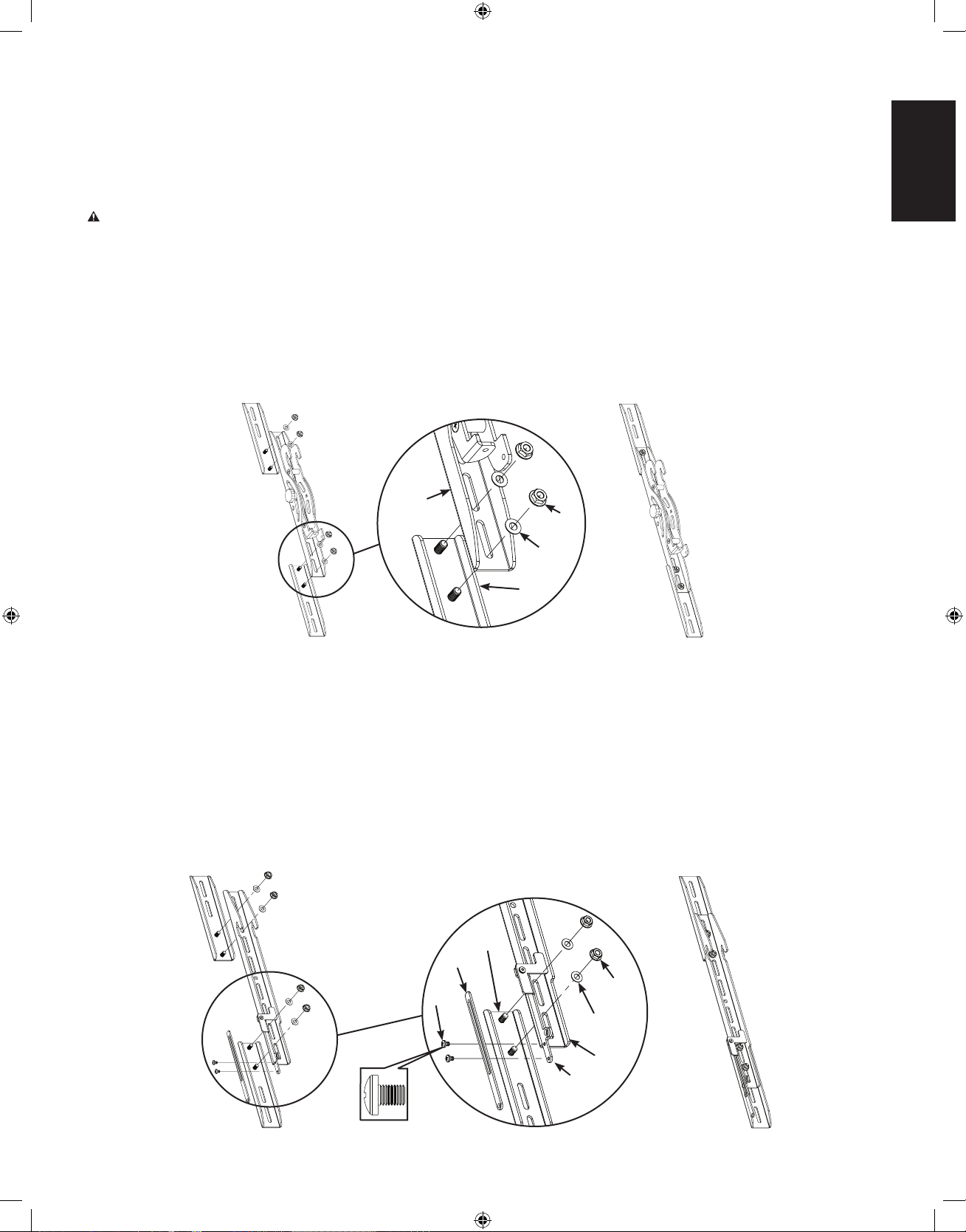
Low Prole Monitor Brackets - See Diagram 1B
To install the Monitor Bracket Extensions (B) place the threaded stud portion through the Low Prole Monitor Bracket (F); then, slide a
Nylon Washer (G) onto the threaded stud.
NOTE: The Monitor Bracket Extensions can be adjusted to the correct height.
Secure the Monitor Bracket Extension (B) by threading on, and tightening a Flange Nut (H) onto each threaded stud of the Monitor
Bracket Extension.
NOTE: If the latch is within reach from the bottom of the televison, the Latch Extension (C) is not required.
The Latch Extension may be adjusted for easy operation on televisions of varying height. Using the 10-32 Screws (N), secure the Latch
Extension (C) to the latch on both Low Prole Monitor Brackets (F).
Diagram 1B
Step 1: Congure the Monitor Brackets
If the hole pattern on the back of your television falls within the vertical reach of the Monitor Brackets (D,E, or F) you do not have to install
the Monitor Bracket Extensions (B). If the hole pattern on the back of your television exceeds the vertical reach of the Monitor Brackets,
the Monitor Bracket Extension must be used.
NOTE: If the Monitor Extension Brackets (B) are required, both Monitor Bracket Extension Brackets must be installed.
CAUTION: Both threaded studs on each Monitor Bracket Extension (B) must pass through the Monitor Bracket (D, E, or F) to
ensure a safe installation.
Tilting Monitor Brackets - See Diagram 1A
To install the Monitor Bracket Extensions (B) place the threaded stud portion through the Tilting Monitor Bracket (D,E); then, slide a Nylon
Washer (G) onto the threaded stud.
NOTE: The Monitor Bracket Extensions can be adjusted to the correct height.
Secure the Monitor Bracket Extension (B) by threading on, and tightening a Flange Nut (H) onto each threaded stud of the Monitor
Bracket Extension (B).
Diagram 1A
H
G
B
D & E
H
G
F
B
C
N
latch
VMPL3_051106_ML.indd 5 7/17/06 11:37:03 AM
Page 6
ENGLISH
NOTE: If you are using the Low Prole Monitor Brackets (F), proceed directly to Step 4 for televisions with a at back and Step
5 for televisions with a curved back.
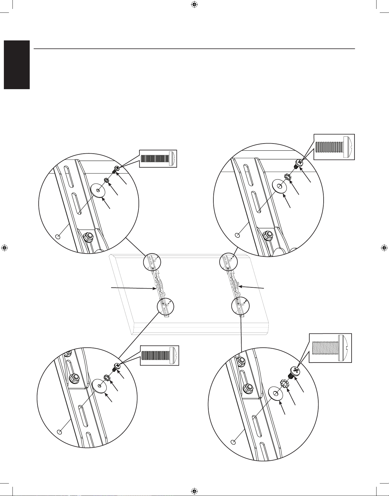
Step 2: Attach Tilting Monitor Brackets to a television with a at back.
NOTE: For televisions with a curved back, or an obstruction near the threaded insert proceed directly to Step 3.
Determine the diameter of the Bolt (O,P,Q,R) your television requires by hand threading them into the threaded insert on the back of the
television. If you encounter any resistance, stop immediately.
Once you have determined the correct diameter Bolt (O,P,Q,R), see the appropriate diagram below, thread the Bolt through the appropriate
Lock Washer (W,X,Y,Z), corresponding Washer (CC,DD), Tilting Monitor Bracket (D,E,) or Monitor Bracket Extension (B), and nally into
the television.
Make sure the Tilting Monitor Brackets (D,E) are vertically centered and level with each other.
Tighten the Bolts (O,P,Q,R) securing the Tilting Monitor Brackets (D,E) to the television.
Diagram 2
Q
M4
Diameter Bolt
M8
Diameter Bolt
M5
Diameter Bolt
M6
Diameter Bolt
DD
Y
D
CC
W
O
CC
X
P
DD
Z
R
E
VMPL3_051106_ML.indd 6 7/17/06 11:37:05 AM
Page 7
ENGLISH
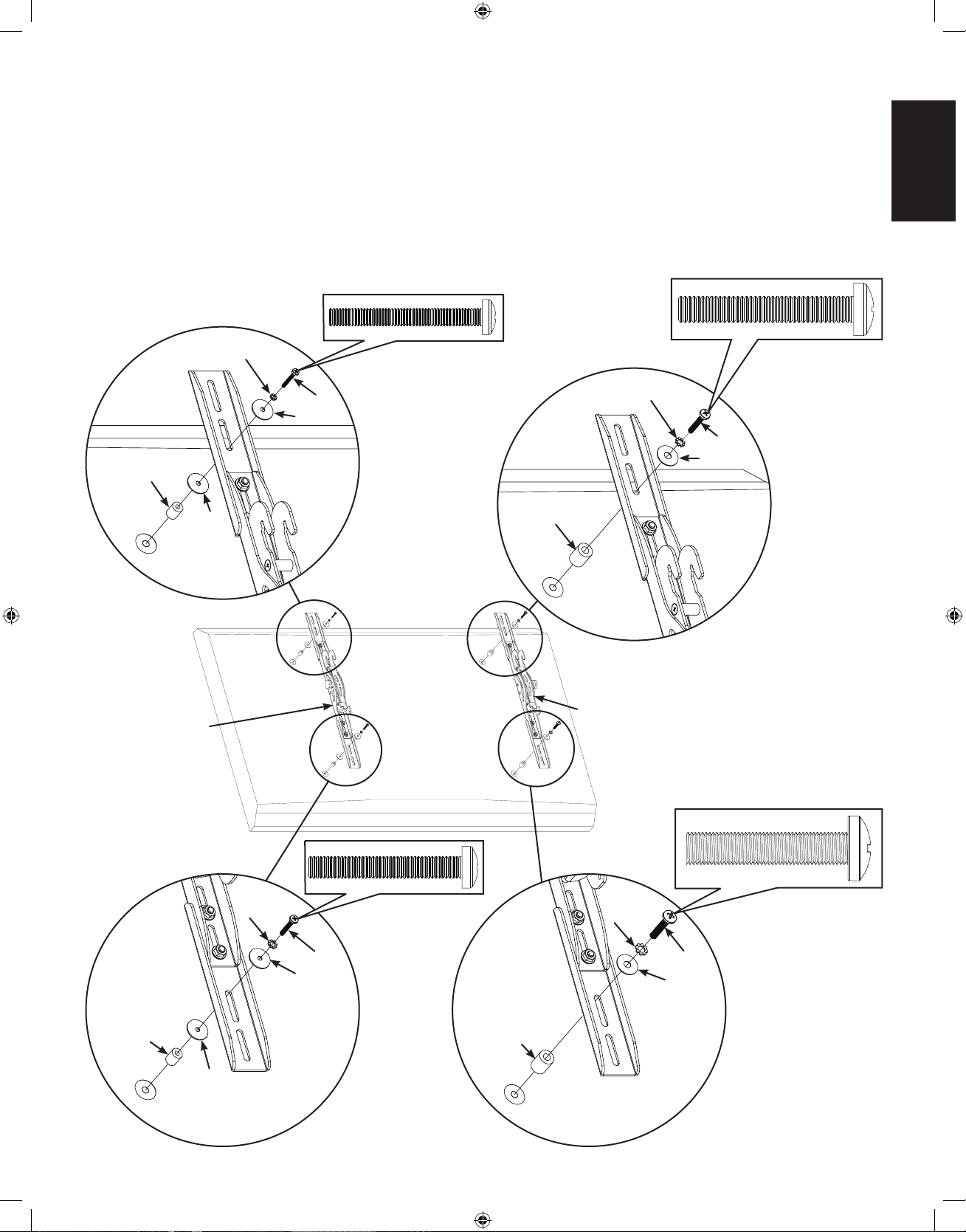
Step 3: Attach Tilting Monitor Brackets to a television with a curved back or an obstruction near the threaded insert.
Note: After Completing Step 3, proceed directly to Step 6.
Determine the diameter of the Bolt (S,T,U,V) your television requires by hand threading them into the threaded insert on the back of the
television. If you encounter any resistance, stop immediately.
Once you have determined the correct diameter Bolt (S,T,U,V), see the appropriate diagram below, thread the Bolt through the appropriate
Lock Washer (W,X,Y,Z), corresponding Washer (CC,DD), Tilting Monitor Bracket (D,E) or Monitor Bracket Extension (B), a second
Washer (CC, M4/M5 diameters only), a Spacer (AA,BB) and nally into the television.
Make sure the Tilting Monitor Brackets (D,E) are vertically centered and level with each other.
Tighten the bolts (S,T,U,V) securing the Tilting Monitor Brackets (D,E) to the television.
Diagram 3
M4
Diameter Bolt
S
M6
Diameter Bolt
M8
Diameter Bolt
M5
Diameter Bolt
W
CC
CC
AA
D
T
X
CC
CC
AA
V
Z
DD
BB
U
Y
DD
BB
E
VMPL3_051106_ML.indd 7 7/17/06 11:37:07 AM
Page 8
ENGLISH
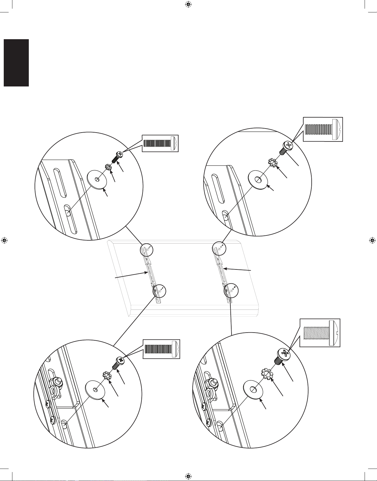
Step 4: Attach Low Prole Monitor Brackets to a television with a at back.
NOTE: For televisions with a curved back, or an obstruction near the threaded insert proceed directly to Step 5.
Determine the diameter of the Bolt (O,P,Q,R) your television requires by hand threading them into the threaded insert on the back of the
television. If you encounter any resistance, stop immediately.
Once you have determined the correct diameter Bolt (O,P,Q,R), see the appropriate diagram below, thread the Bolt through the appropriate
Lock Washer (W,X,Y,Z), corresponding Washer (CC,DD), Low Prole Monitor Bracket (F) or Monitor Bracket Extension (B), and nally
into the television.
Make sure the Low Prole Monitor Brackets (F) are vertically centered and level with each other.
Tighten the Bolts (O,P,Q,R) securing the Low Prole Monitor Brackets (F) to the television.
Diagram 4
Q
M4
Diameter Bolt
M8
Diameter Bolt
M5
Diameter Bolt
M6
Diameter Bolt
DD
Y
F
CC
W
O
CC
X
P
DD
Z
R
F
VMPL3_051106_ML.indd 8 7/17/06 11:37:09 AM
Page 9
ENGLISH
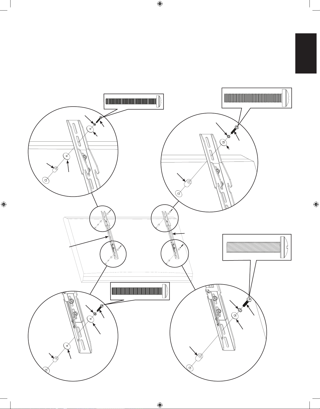
Step 5: Attach Low Prole Monitor Brackets to a television with a curved back or an obstruction near the threaded insert.
Determine the diameter of the Bolt (S,T,U,V) your television requires by hand threading them into the threaded insert on the back of the
television. If you encounter any resistance, stop immediately.
Once you have determined the correct diameter Bolt (S,T,U,V), see the appropriate diagram below, thread the Bolt through the appropriate
Lock Washer (W,X,Y,Z), corresponding Washer (CC,DD), Low Prole Monitor Bracket (F) or Monitor Bracket Extension (B), a second
Washer (CC, M4/M5 diameters only), a Spacer (AA,BB) and nally into the television.
Make sure the Low Prole Monitor Brackets (F) are vertically centered and level with each other.
Tighten the Bolts (S,T,U,V) securing the Low Prole Monitor Brackets (F) to the television.
Diagram 5
M4
Diameter Bolt
M6
Diameter Bolt
M8
Diameter Bolt
M5
Diameter Bolt
S
W
CC
CC
AA
F
T
X
CC
CC
AA
V
Z
DD
BB
U
Y
DD
BB
F
VMPL3_051106_ML.indd 9 7/17/06 11:37:11 AM
Page 10
ENGLISH
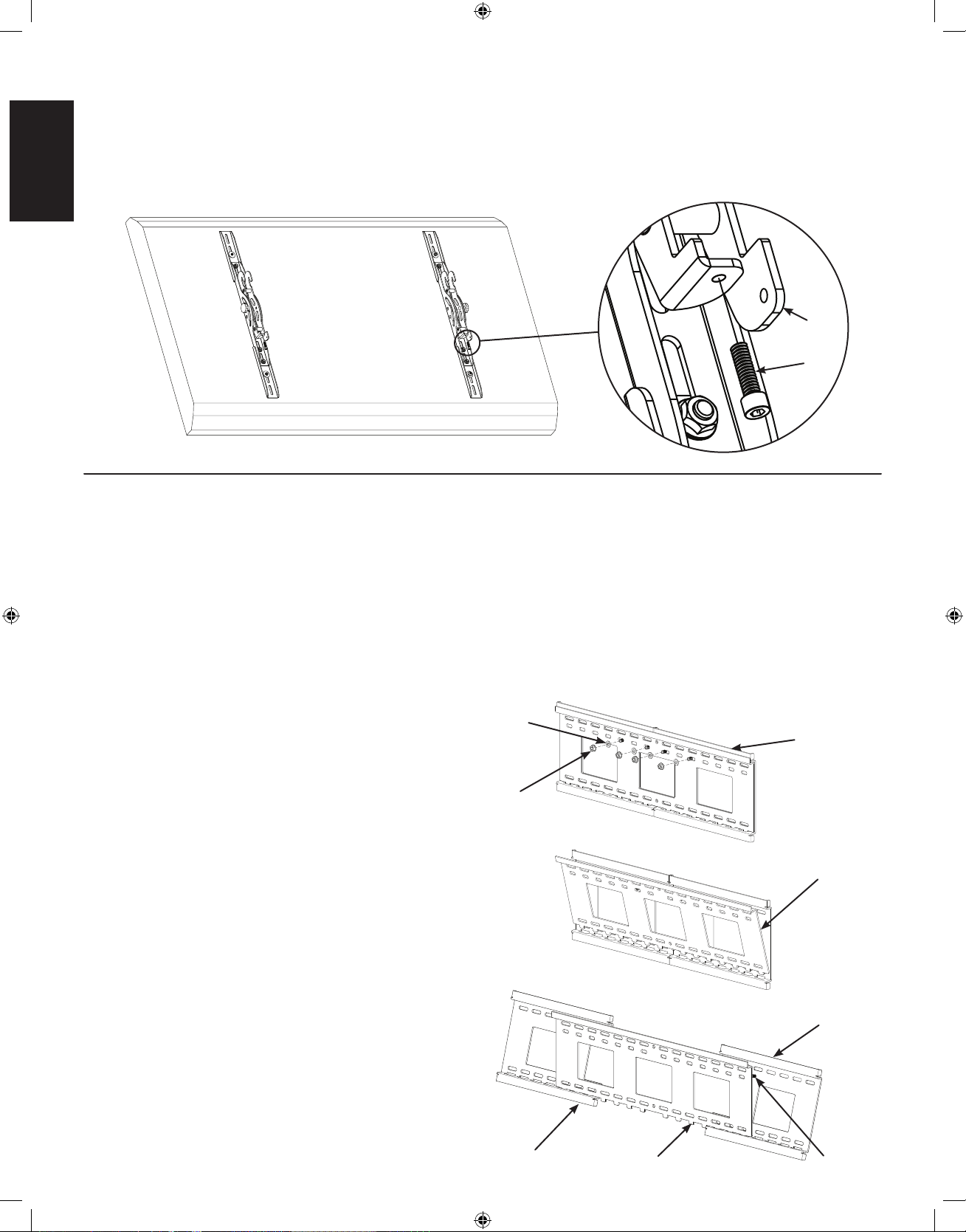
Step 6: Add Safety Bolts (Tilting Monitor Brackets only)
Thread a Safety Bolt (I) into the bottom portion of each Tilting Monitor Bracket (D & E) approximately 1/4″ as shown in Diagram 6.
NOTE: Do not tighten the Safety bolt (I). The Safety Bolt is tightened after the television and Tilting Monitor Brackets (D & E) are
attached to the Wall Plate Assembly (A).
Step 7: Congure Wall Plate Assembly
The Wall Plate Assembly (A) can be adjusted in width from 27″ to 42″ [686 mm to 1067 mm]. Determine how wide you want the Wall
Plate Assembly based on the following criteria:
• Width of television (Wall Plate Assembly should be congured so the total width is less than the overall width of your television)
• Width of Hole Pattern on television (Wall Plate Assembly should be wider than the horizontal distance between threaded inserts on the
back of your TV by at least 2″ [50.8 mm])
• Stud Spacing (Sanus recommends attaching Wall Plate Assembly to three studs for televisions over 125 lbs. [56.7 Kg])
To adjust the width of the Wall Plate Assembly (A):
Diagram 6
I
D & E
Remove the Center Plate of the Wall Plate Assembly (A) as
shown in Diagram 7B.
Seperate the Left and Right Extension of the Wall Plate Assembly
(A) and set them to so that their outer edges are equal to the
desired width; then, insert the Center Plate so the teeth on its
bottom t into the slots in the Left and Right Extension, making
sure that the Threaded Studs t through the center row on holes
in the Center Plate as shown in Diagram 7C.
Diagram 7A
Flange
Nut
Wall Plate
Assembly (A)
Nylon
Washer
Diagram 7B
Center
Plate
Diagram 7C
Left
Extension
Center
Plate
Right
Extension
Threaded
Studs
Remove each Flange Nut and Nylon Washer as shown in
Diagram 7A
VMPL3_051106_ML.indd 10 7/17/06 11:37:14 AM
Page 11

ENGLISH
CAUTION: All four Threaded Studs must pass through
the Center Plate for the installation to be safe.
Using the previously removed Flange Nuts and Nylon
Washers, secure the Right and Left Extension to the Center
Plate as shown in Diagram 7D, and securly tighten the Flange
Nuts.
Step 8: Mount the Wall Plate Assembly; Wood Stud, Brick, Solid Concrete, and Concrete Block mounting options are provided.
CAUTION: On all installations, two Lag Bolts (K) must pass through each Wall Plate Extension. Only the fth and sixth Lag
Bolts may pass through the Center Plate (A).
Diagram 7D
Flange
Nut
Nylon
Washer
Left
Extension
Center
Plate
Right
Extension
Wood Stud Mounting:
CAUTION: Do not overtighten the Lag Bolts (K). Tighten
the Lag Bolts only until the lag Bolt Washer (L) is pulled
rmly against the Wall Plate Assembly (A).
NOTE: The Wall Plate Assembly (A) must be mounted
on two or three studs at least 12″ [304.8 mm] apart,
and three studs are recommended for televisions over
125 lbs [56.7 Kg].
Use a high quality stud sensor to locate two or three adjacent
studs; then, using the Wall Plate Assembly (A), as a template,
mark a location at each of the studs using the top row of slots
on the Wall Plate Assembly and the corresponding slot in the
bottom row.
Pre-drill a 2.5″ [63.5 mm] deep into the studs, using a 3/16″
drill bit. Place the Wall Plate Assembly (A) with its at surface
against the wall and the Flange Nuts toward the top; then
secure the Wall Plate Assembly using the Lag Bolts (K) and
Lag Bolt Washers (L) as shown in Diagram 8A.
Brick, Solid Concrete, and Concrete Block Mounting:
Use the Wall Plate Assembly (A) as a template to mark six
locations on the wall. Three in the top row of slots and three
more directly below in the bottom row of slots.
CAUTION: Never drill into the mortar between the
blocks.
Carefully pre-drill six 2.5″ [63.5 mm] deep holes with a 1/2″
masonry bit.
Insert a Concrete Anchor (M) into each pre-drilled hole so it
is ush with the concrete, brick, or concrete block surface,
even if there is a layer of drywall or other material in front of
the surface.
Place the Wall Plate Assembly (A) with its at surface against
the wall and the Flange Nuts toward the top; then, attach the
Wall Plate Assembly to the wall using the six Lag Bolts (K)
and Lag Bolt Washers (L) as shown in Diagram 8B.
Diagram 8A
A
K
L
Flange
Nut
Diagram 8B
Flange
Nut
M
K
L
A
VMPL3_051106_ML.indd 11 7/17/06 11:37:17 AM
Page 12

ENGLISH
Step 9: Hang the Television onto the Wall Plate
CAUTION: Some televisions may require two people to lift. Sanus is not responsible for personal injury or product damage.
CAUTION: The Monitor Brackets must hang on the left and right extension panels of the Wall Plate Assembly, they can not
hang directly on the center plate.
NOTE: For the Low Prole Monitor Bracket, make sure the latch is in the open position.
Hook the Tilting Monitor Brackets (D,E) as shown in Diagram 9A, or the Low Prole Monitor Brackets (F) as shown in Diagram 9B over the
top of the Wall Plate Assembly (A); then, let the bottom of the Monitor Brackets rotate in under the bottom of the Wall Plate Assembly.
Diagram 9A
D,E
A
Bottom
Tab
On the Tilting Monitor Brackets (D,E) tighten Safety Bolts (I) with the Allen Key (J) so that they sit behind the bottom tab on the Wall Plate
Assembly (A) as shown in Diagram 9C or rotate the Latch downward on the Low Prole Monitor Brackets (F) as shown in Diagram 9D.
On Tilting Monitor Brackets (D,E) only, set tension of the knobs and you are free to adjust your new at panel television without having to
re-tighten the knobs.
Diagram 9B
F
A
Bottom
Tab
Diagram 9C
D,E
Bottom
Tab
I
Diagram 9D
Sanus Systems 2221 Hwy 36 West, Saint Paul, MN 55113 USA
Customer Service: 800.359.5520. See complementary Sanus products at www.sanus.com
Latch
VMPL3_051106_ML.indd 12 7/17/06 11:37:19 AM
Page 13

ESPAÑOL
Instrucciones de ensamblaje del modelo: VMPL3
Gracias por elegir un soporte de pared VisionMount™ de Sanus Systems. El modelo VMPL3 ha sido diseñado para sostener televisores
de pantalla plana LCD o plasma, de 27 pulgadas a 84 pulgadas, y con un peso de hasta 127 kg.
PRECAUCIÓN: El tamaño y peso de su televisor de pantalla grande no deberá exceder las 84 pulgadas en diagonal ni los
127 kg, la capacidad máxima de carga del soporte. Nunca use piezas defectuosas. La instalación incorrecta podría ocasionar
daños o lesiones graves. No utilice este producto para nes no explícitamente especicados por Sanus Systems.
Si no entiende estas instrucciones o si tiene alguna duda con respecto a la seguridad de la instalación, llame a un contratista cualicado
o comuníquese con Sanus llamando al 800.359.5520 (en EE.UU.) o al 31 (0) 20 5708938 (en Europa). Puede también visitar nuestro
sitio en www.sanus.com. Nuestros representantes del servicio al cliente pueden ayudarle a responder cualquier duda sobre la instalación
o con respecto a piezas faltantes o defectuosas. Las piezas de repuesto para los productos comprados a través de un distribuidor
autorizado se enviarán directamente a usted. Revise los productos cuidadosamente para asegurarse de que ninguna pieza falte ni
presente defectos. Sanus Systems no será responsable por daños ni lesiones debidos al montaje, ensamblaje o uso incorrectos. Llame
a Sanus Systems antes de devolver los productos al punto de compra.
NOTA: La tornillería suministrada para instalación en paredes no es para paredes con vigas de metal ni para paredes de
concreto. Si tiene alguna duda sobre la estructura de la pared, consulte a un contratista sobre la instalación. Sanus hace todo lo
posible para asegurar que se incluya todo el equipo de instalación necesario. Si necesita tornillería que no haya sido incluida,
consulte en una ferretería local o llame a Sanus Systems.
Herramientas necesarias: Taladro, broca de 3/16 pulgadas (broca para concreto de 1/2 pulgada para instalaciones sobre ladrillo,
concreto o bloques de hormigón), juego de llaves mecánicas, destornillador Phillips.
Piezas y tornillería suministradas: (Todos los sujetadores roscados se muestran en tamaño real.)
L A U N I Ó N D E F O R M A Y F U N C I Ó N
Conjunto de placa de pared - A
Cantidad: 1
Soporte derecho de inclinación
del monitor - D
Cantidad: 1
Extensión de soporte de monitor - B
Cantidad: 4
Soporte izquierdo de inclinación
del monitor - E
Cantidad: 1
Extensión del seguro - C
Cantidad: 2
Soporte de monitor de
perl bajo - F
Cantidad: 2
Sanus Systems 2221 Hwy 36 West, Saint Paul, MN 55113 USA
Servicio de atención al cliente: 800.359.5520. Vea los productos complementarios de Sanus en el sitio www.sanus.com
VMPL3_051106_ML.indd 13 7/17/06 11:37:20 AM
Page 14

ESPAÑOL
Perno M4 x 16 mm - O
Cantidad: 4
Perno M5 x 16 mm - P
Cantidad: 4
Perno M6 x 16 mm - Q
Cantidad: 4
Perno M8 x 16 mm - R
Cantidad: 4
Perno M4 x 35 mm - S
Cantidad: 4
Perno M5 x 35 mm - T
Cantidad: 4
Perno M6 x 40 mm - U
Cantidad: 4
Perno M8 x 40 mm - V
Cantidad: 4
Arandela de
seguridad M4 - W
Cantidad: 4
Arandela de
seguridad M5 - X
Cantidad: 4
Arandela de
seguridad M6 - Y
Cantidad: 4
Arandela de
seguridad M8 - Z
Cantidad: 4
Espaciador M4/M5 - AA
Cantidad: 4
Espaciador M6/M8 - BB
Cantidad: 4
Arandela M4/M5 - CC
Cantidad: 8
Arandela M6/M8 - DD
Cantidad: 4
Arandela
de nilón - G
Cantidad: 8
Tuerca
embridada - H
Cantidad: 8
Perno de
seguridad - I
Cantidad: 2
Llave allen - J
Cantidad: 1
Tirafondo - K
Cantidad: 6
Arandela para tirafondo - L
Cantidad: 6
Anclaje para concreto - M
Cantidad: 6
Tornillo 10-32 - N
Cantidad: 4
VMPL3_051106_ML.indd 14 7/17/06 11:37:21 AM
Page 15

ESPAÑOL
Soportes de monitor de perl bajo: Vea el diagrama 1B
Para instalar las extensiones de soporte de monitor (B) haga pasar la parte del vástago roscado a través del soporte de monitor de perl
bajo (F); deslice luego una arandela de nilón (G) sobre el vástago roscado.
NOTA: Las extensiones de soporte de monitor pueden ajustarse a la altura correcta.
Fije la extensión de soporte de monitor (B) enroscando y ajustando una tuerca embridada (H) en cada vástago roscado de la extensión.
NOTA: Si el pasador puede alcanzarse desde la parte inferior del televisor, no será necesaria la extensión del seguro (C).
La extensión del seguro deberá ajustarse para facilitar el accionamiento en televisores de diversas alturas. Utilizando los tornillos 10-32 (N),
je la extensión del seguro (C) a este último en los dos soportes de monitor de perl bajo (F).
Diagrama 1B
Paso 1: Conguración de los soportes de monitor
Si el patrón de agujeros de la parte posterior de su televisor está dentro del alcance vertical de los soportes de monitor (D, E o F), no
necesita instalar las extensiones de soporte de monitor (B). En caso contrario sí deberá utilizar las extensiones.
NOTA: Si son necesarias las extensiones de soporte de monitor (B), deberán instalarse ambas.
PRECAUCIÓN: Los dos vástagos roscados situados en cada extensión de soporte de monitor (B) deben pasar a través del
soporte de monitor (D, E o F) para asegurar que la instalación sea segura.
Soportes de inclinación del monitor: Vea el diagrama 1A
Para instalar las extensiones de soporte de monitor (B) haga pasar la parte del vástago roscado a través del soporte de inclinación del
monitor (D, E); deslice luego una arandela de nilón (G) sobre el vástago roscado.
NOTA: Las extensiones de soporte de monitor pueden ajustarse a la altura correcta.
Fije la extensión de soporte de monitor (B) enroscando y ajustando una tuerca embridada (H) en cada vástago roscado de la extensión (B).
Diagrama 1A
H
G
B
D y E
H
G
F
B
C
N
seguro
VMPL3_051106_ML.indd 15 7/17/06 11:37:22 AM
Page 16

ESPAÑOL
NOTA: Si está usando soportes de monitor de perl bajo (F), pase directamente al paso 4 para televisores con la parte trasera
plana y al paso 5 para televisores con la parte trasera curva.
Paso 2: Acoplamiento de los soportes de inclinación del monitor a un televisor con la parte trasera plana
NOTA: Para televisores con la parte trasera curva o con una obstrucción cerca del inserto roscado, pase directamente al paso 3.
Determine primero el diámetro de perno (O, P, Q, R) que necesita el televisor. Para ello deberá probar los pernos con la mano en el
inserto roscado que se encuentra en la parte trasera del mismo. Si encuentra alguna resistencia, deténgase inmediatamente.
Una vez que se haya encontrado el perno del diámetro correcto (O, P, Q, R), y siguiendo el diagrama correspondiente de más abajo,
haga pasar el perno por la arandela de seguridad apropiada (W, X, Y, Z), la arandela correspondiente (CC, DD), el soporte de inclinación
del monitor (D, E) o extensión de soporte de monitor (B), y nalmente enrósquelo en el televisor.
Asegúrese de que los soportes de inclinación del monitor (D,E) queden centrados verticalmente y nivelados entre sí.
Ajuste los pernos (O, P, Q, R) para jar los soportes de inclinación del monitor (D, E) al televisor.
Diagrama 2
Q
Perno de
diámetro M4
Perno de
diámetro M8
Perno de
diámetro M5
Perno de
diámetro M6
DD
Y
D
CC
W
O
CC
X
P
DD
Z
R
E
VMPL3_051106_ML.indd 16 7/17/06 11:37:22 AM
Page 17

ESPAÑOL
Paso 3: Acoplamiento de los soportes de inclinación del monitor a un televisor con la parte trasera curva o con una
obstrucción cerca del inserto roscado
Nota: Después de completar el paso 3, proceda directamente al paso 6.
Determine primero el diámetro de perno (S, T, U, V) que necesita el televisor. Para ello deberá probar los pernos con la mano en el
inserto roscado que se encuentra en la parte trasera del mismo. Si encuentra alguna resistencia, deténgase inmediatamente.
Una vez que se haya encontrado el perno del diámetro correcto (S, T, U, V), y siguiendo el diagrama correspondiente de más abajo,
haga pasar el perno por la arandela de seguridad apropiada (W, X, Y, Z), la arandela correspondiente (CC,DD), el soporte de inclinación
del monitor (D, E) o extensión de soporte de monitor (B), una segunda arandela (CC, para diámetros M4/M5 solamente), un espaciador
(AA, BB) y nalmente enrósquelo en el televisor.
Asegúrese de que los soportes de inclinación del monitor (D, E) queden centrados verticalmente y nivelados entre sí.
Ajuste los pernos (S, T, U, V) para jar los soportes de inclinación del monitor (D, E) al televisor.
Diagrama 3
Perno de
diámetro M4
S
Perno de
diámetro M6
Perno de
diámetro M8
Perno de
diámetro M5
W
CC
CC
AA
D
T
X
CC
CC
AA
V
Z
DD
BB
U
Y
DD
BB
E
VMPL3_051106_ML.indd 17 7/17/06 11:37:24 AM
Page 18

ESPAÑOL
Paso 4: Acoplamiento de soportes de monitor de perl bajo a un televisor con la parte trasera plana
NOTA: Para televisores con la parte trasera curva o con una obstrucción cerca del inserto roscado, pase directamente al paso 5.
Determine primero el diámetro de perno (O, P, Q, R) que necesita el televisor. Para ello deberá probar los pernos con la mano en el
inserto roscado que se encuentra en la parte trasera del mismo. Si encuentra alguna resistencia, deténgase inmediatamente.
Una vez que se haya encontrado el perno del diámetro correcto (O, P, Q, R), y siguiendo el diagrama correspondiente de más abajo,
haga pasar el perno por la arandela de seguridad apropiada (W, X, Y, Z), la arandela correspondiente (CC, DD), el soporte de monitor de
perl bajo (F) o extensión de soporte de monitor (B), y nalmente enrósquelo en el televisor.
Asegúrese de que los soportes de monitor de perl bajo (F) queden centrados verticalmente y nivelados entre sí.
Ajuste los pernos (O, P, Q, R) para jar los soportes de monitor de perl bajo (F) al televisor.
Diagrama 4
Q
Perno de
diámetro M4
Perno de
diámetro M8
Perno de
diámetro M5
Perno de
diámetro M6
DD
Y
F
CC
W
O
CC
X
P
DD
Z
R
F
VMPL3_051106_ML.indd 18 7/17/06 11:37:24 AM
Page 19

ESPAÑOL
Paso 5: Acoplamiento de los soportes de monitor de perl bajo a un televisor con la parte trasera curva o con una
obstrucción cerca del inserto roscado
Determine primero el diámetro de perno (S, T, U, V) que necesita el televisor. Para ello deberá probar los pernos con la mano en el
inserto roscado que se encuentra en la parte trasera del mismo. Si encuentra alguna resistencia, deténgase inmediatamente.
Una vez que se haya encontrado el perno del diámetro correcto (S, T, U, V), y siguiendo el diagrama correspondiente de más abajo, haga
pasar el perno por la arandela de seguridad apropiada (W, X, Y, Z), la arandela correspondiente (CC,DD), el soporte de monitor de perl
bajo (F) o extensión de soporte de monitor (B), una segunda arandela (CC, para diámetros M4/M5 solamente), un espaciador (AA, BB)
y nalmente enrósquelo en el televisor.
Asegúrese de que los soportes de monitor de perl bajo (F) queden centrados verticalmente y nivelados entre sí.
Ajuste los pernos (S, T, U, V) para jar los soportes de monitor de perl bajo (F) al televisor.
Diagrama 5
Perno de
diámetro M4
Perno de
diámetro M6
Perno de
diámetro M8
Perno de
diámetro M5
S
W
CC
CC
AA
F
T
X
CC
CC
AA
V
Z
DD
BB
U
Y
DD
BB
F
VMPL3_051106_ML.indd 19 7/17/06 11:37:25 AM
Page 20

ESPAÑOL
Paso 6: Agregado de los pernos de seguridad (soportes de inclinación del monitor solamente)
Enrosque un perno de seguridad (I) en la parte inferior de cada soporte de inclinación del monitor (D y E) haciéndolo penetrar 0,6 cm
aproximadamente, como se ilustra en el diagrama 6.
NOTA: No ajuste el perno de seguridad (I). El perno deberá ajustarse una vez que el televisor y los soportes de inclinación del
monitor (D y E) estén acoplados al conjunto de placa de pared (A).
Paso 7: Conguración del conjunto de placa de pared
La anchura del conjunto de placa de pared (A) puede ajustarse desde 68,6 cm hasta 106,7 cm. Determine la anchura deseada para
la placa de pared basándose en los criterios siguientes:
• Anchura del televisor (La placa de pared deberá congurarse de manera que la anchura total sea menor que la anchura general del televisor.)
• Anchura del patrón de agujeros del televisor (El conjunto de placa de pared debería ser al menos 5,1 cm más ancho que la distancia
horizontal entre los insertos roscados de la parte trasera del televisor.)
• Espacio entre vigas (Sanus recomienda acoplar la placa de pared a 3 vigas en el caso de televisores de más de 56,7 kg de peso.)
Para ajustar la anchura del conjunto de placa de pared (A):
Diagrama 6
I
D y E
Retire la placa central del conjunto de placa de pared (A) como
se ilustra en el diagrama 7B.
Separe las extensiones izquierda y derecha del conjunto de
placa de pared (A) y colóquelas de forma tal que sus bordes
exteriores coincidan con la anchura deseada; inserte luego la
placa central de manera que los dientes de la parte inferior
de ésta encajen en las ranuras de las extensiones izquierda y
derecha, y asegurándose de que los insertos roscados pasen a
través de la hilera central de agujeros de la placa central. Vea
el diagrama 7C.
Diagrama 7A
Tuerca
embridada
Conjunto de
placa de pared (A)
Arandela
de nilón
Diagrama 7B
Placa
central
Diagrama 7C
Extensión
izquierda
Placa
central
Extensión
derecha
Vástagos
roscados
Retire todas las tuercas embridadas y arandelas de nilón como
se ilustra el diagrama en 7A.
VMPL3_051106_ML.indd 20 7/17/06 11:37:26 AM
Page 21

ESPAÑOL
PRECAUCIÓN: Los cuatro vástagos roscados deben
pasar a través de la placa central para que la instalación
sea segura.
Usando las tuercas embridadas y arandelas de nilón que
sacó antes, je las extensiones derecha e izquierda a la placa
central como se ilustra en el diagrama 7D, y luego ajuste
rmemente las tuercas.
Paso 8: Montaje del conjunto de placa de pared; se proporcionan opciones de montaje para vigas de madera, ladrillo, concreto y
bloques de hormigón
PRECAUCIÓN: En todas las instalaciones, se deben pasar dos tirafondos (K) por cada extensión de la placa de pared.
Únicamente el quinto y sexto tirafondos pueden pasar por la placa central (A).
Diagrama 7D
Tuerca
embridada
Arandela
de nilón
Extensión
izquierda
Placa
central
Extensión
derecha
Montaje sobre viga de madera:
PRECAUCIÓN: No ajuste demasiado los tirafondos
(K). Ajústelos únicamente hasta que la arandela
correspondiente (L) quede rmemente apoyada contra el
conjunto de placa de pared (A).
NOTA: El conjunto de placa de pared (A) debe instalarse
sobre dos o tres vigas separadas al menos por 30,5 cm,
y se recomiendan tres vigas para televisores de más de
56,7 kg de peso.
Utilice un detector de vigas de alta calidad para localizar dos
vigas adyacentes; a continuación, utilizando el conjunto de placa
de pared (A) como plantilla, marque la posición en cada una de
las vigas utilizando la hilera superior de ranuras de la placa de
pared y las ranuras correspondientes de la hilera inferior.
Perfore con antelación agujeros de 6,4 cm de profundidad
en las vigas utilizando una broca de 3/16 pulgadas. Coloque
el conjunto de placa de pared (A) contra la pared con su
supercie plana contra ésta y las tuercas embridadas hacia
la parte superior; luego je la placa de pared utilizando los
tirafondos (K) y las arandelas correspondientes (L) como se
ilustra en el diagrama 8A.
Montaje en ladrillo, concreto y bloques de hormigón:
Utilice el conjunto de placa de pared (A) como plantilla para
marcar seis lugares en la pared: Tres en la hilera superior de
ranuras y tres más en la hilera inferior directamente debajo
de éstos.
PRECAUCIÓN: Nunca perfore en el cemento situado
entre los bloques.
Perfore previa y cuidadosamente seis agujeros de 6,4 cm de
profundidad utilizando una broca para concreto de 1/2 pulgada.
Inserte un anclaje para concreto (M) en cada uno de los agujeros
perforados de manera tal que quede a ras con la supercie de
cemento, ladrillo o bloques de hormigón, aun si hay una capa
de yeso o material similar que cubra la supercie.
Coloque el conjunto de placa de pared (A) contra la pared con
su supercie plana contra la misma y las tuercas embridadas
hacia la parte superior; luego je la placa de pared a esta
última utilizando los 6 tirafondos (K) y las arandelas
correspondientes (L) como se ilustra en el diagrama 8B.
Diagrama 8A
A
K
L
Tuerca
embridada
Diagrama 8B
Tuerca
embridada
M
K
L
A
VMPL3_051106_ML.indd 21 7/17/06 11:37:27 AM
Page 22

Paso 9: Colgado del televisor en la placa de pared
PRECAUCIÓN: Se requieren dos personas para levantar algunos televisores. Sanus no será responsable por lesiones
personales ni daños ocasionados a los productos.
PRECAUCIÓN: Los soportes de monitor deben colgar de los paneles de extensión izquierdo y derecho del conjunto de placa
de pared; no pueden colgar directamente de la placa central.
NOTA: En el caso de soportes de monitor de perl bajo, verique que el seguro esté en la posición abierta.
Enganche los soportes de inclinación del monitor (D, E) como se ilustra en el diagrama 9A, o los soportes de monitor de perl bajo (F)
como se ilustra en el diagrama 9B, de la parte superior del conjunto de placa de pared (A); luego deje que la parte inferior de los soportes
de monitor gire debajo de la parte inferior de la placa de pared.
Diagrama 9A
ESPAÑOL
En los soportes de inclinación del monitor (D, E), ajuste los pernos de seguridad (I) con la llave allen (J) para que queden detrás de la
pestaña inferior del conjunto de placa de pared (A) como se ilustra en el diagrama 9C, o bien gire el seguro hacia abajo en los soportes
de monitor de perl bajo (F) como se ilustra en el diagrama 9D.
En los soportes de inclinación del monitor (D, E) únicamente, congure la tensión de las perillas para que su nuevo televisor de pantalla
plana pueda ajustarse sin tener que volver a ajustar las perillas.
Diagrama 9C
D, E
A
Pestaña
inferior
Diagrama 9B
F
A
Pestaña
inferior
Diagrama 9D
D, E
Pestaña
inferior
I
Seguro
Sanus Systems 2221 Hwy 36 West, Saint Paul, MN 55113 USA
Servicio de atención al cliente: 800.359.5520. Vea los productos complementarios de Sanus en el sitio www.sanus.com
VMPL3_051106_ML.indd 22 7/17/06 11:37:28 AM
Page 23

FRANÇAIS
Instructions de montage pour le modèle : VMPL3
Nous vous remercions d’avoir choisi un montant mural VisionMount™ de Sanus Systems. Le modèle VMPL3 est conçu pour soutenir des
téléviseurs à écran plat à afchage LCD ou à plasma de 27 à 84 pouces et pesant jusqu’à 127 kg.
ATTENTION : la taille et le poids de votre téléviseur grand écran ne doivent pas dépasser 84 pouces (mesurés en diagonale) et 127,3 kg
,
la capacité de charge maximale du support. N’utilisez jamais de pièces défectueuses. Une installation incorrecte peut entraîner des
dommages ou des blessures graves. Ce produit ne doit être utilisé que pour des usages explicitement spéciés par Sanus Systems.
Si vous ne comprenez pas ces instructions ou si vous avez un doute quant à la sécurité de cette installation, veuillez faire appel
à un technicien qualié ou communiquez avec Sanus en composant le 1-800-359-5520 (aux É.-U.), ou le 31 (0) 20 5708938 (pour
l’Europe). Vous pouvez aussi visiter notre site Web à www.sanus.com. Les représentants de notre service à la clientèle peuvent répondre
rapidement à toute question concernant l’installation ou des pièces manquantes ou endommagées. Les pièces de rechange de produits
achetés auprès de distributeurs agréés vous seront livrées directement. Vériez soigneusement qu’il n’y a aucune pièce manquante ou
défectueuse. Sanus Systems ne pourra être tenu responsable de dommages ou de blessures dus à un montage incorrect, un assemblage
incorrect ou un usage incorrect. Veuillez contacter Sanus Systems avant de renvoyer des produits au point de vente.
REMARQUE : le matériel pour montage mural fourni n’est pas adapté aux cloisons à charpente métallique ni aux anciennes
cloisons en briques de mâchefer. Si vous n’êtes pas certain de la nature de votre cloison, veuillez consulter un entrepreneur.
Sanus Systems prend soin d’inclure toute la visserie nécessaire au montage d’un téléviseur. Si toutefois la visserie dont vous
avez besoin n’est pas incluse, consultez une quincaillerie locale ou contactez directement Sanus Systems.
Outils nécessaires : perceuse, mèche de 3/16 pouce (mèche à maçonnerie de 1/2 pouce permettant de percer les surfaces en béton,
les briques ou les parpaings), jeu de clés, tournevis cruciforme.
Pièces et matériel fournis : (toutes les xations letées sont illustrées grandeur nature.)
L’ U N I O N D E L A F O R M E E T D E L A F O N C T I O N
Plaque murale - A
Qté 1
Support de moniteur pour
inclinaison à droite - D
Qté 1
Extension du support de
moniteur - B
Qté 4
Support de moniteur pour
inclinaison à gauche - E
Qté 1
Extension du dispositif de
verrouillage - C
Qté 2
Support de moniteur n - F
Qté 2
Sanus Systems 2221 Hwy 36 West, Saint Paul, MN 55113, États-Unis
Service à la clientèle : 800.359.5520. Pour les produits Sanus complémentaires, visitez le site www.sanus.com
VMPL3_051106_ML.indd 33 7/17/06 11:37:38 AM
Page 24
FRANÇAIS
Vis M4 x 16 mm - O
Qté 4
Vis M5 x 16 mm - P
Qté 4
Vis M6 x 16 mm - Q
Qté 4
Vis M8 x 16 mm - R
Qté 4
Vis M4 x 35 mm - S
Qté 4
Vis M5 x 35 mm - T
Qté 4
Vis M6 x 40 mm - U
Qté 4
Vis M8 x 40 mm - V
Qté 4
Rondelle de blocage M4 - W
Qté 4
Rondelle de blocage M5 - X
Qté 4
Rondelle de blocage M6 - Y
Qté 4
Rondelle de blocage M8 - Z
Qté 4
Entretoise M4/M5 - AA
Qté 4
Entretoise M6/M8 - BB
Qté 4
Rondelle M4/M5 - CC
Qté 8
Rondelle M6/M8 - DD
Qté 4
Rondelle en nylon - G
Qté 8
Écrou à embase - H
Qté 8
Vis de sécurité - I
Qté 2
Clé Allen - J
Qté 1
Tire-fond - K
Qté 6
Rondelle de tire-fond - L
Qté 6
Vis d’ancrage pour béton - M
Qté 6
Vis 10-32 - N
Qté 4
VMPL3_051106_ML.indd 34 7/17/06 11:37:39 AM
Page 25

FRANÇAIS
Supports de moniteur n - voir le schéma 1B
Pour installer les extensions du support de moniteur (B), insérez le montant leté dans le support de moniteur n (F), puis enlez une
rondelle en nylon (G) sur le montant.
REMARQUE : les extensions du support de moniteur peuvent être réglées à la hauteur voulue.
Fixez l’extension du support de moniteur (B) en enlant et en serrant un écrou à embase (H) sur chaque montant leté de l’extension.
REMARQUE : si le dispositif de verrouillage est à une distance correcte de la partie inférieure du téléviseur, l’extension (C) du
dispositif de verrouillage n’est pas nécessaire.
Il est possible de régler l’extension du dispositif de verrouillage pour faciliter l’utilisation de téléviseurs de hauteurs différentes. À l’aide des
vis 10-32 (N), xez l’extension (C) sur le dispositif de verrouillage des deux supports de moniteur ns (F).
Schéma 1B
Étape 1 : Conguration des supports du moniteur
Si la conguration des trous de montage à l’arrière du téléviseur s’insère verticalement dans les supports de moniteur (D, E ou F), vous
n’aurez pas à installer les extensions du support de moniteur (B). Si la conguration des trous dépasse les supports de moniteur, il faudra
monter les extensions du support.
REMARQUE : si les supports d’extension du moniteur (B) s’avèrent nécessaires, les deux supports doivent être installés.
ATTENTION : les deux montants letés sur chaque extension du support de moniteur (B) doivent passer par le support du
moniteur (D, E ou F) pour assurer une installation sans risque.
Supports pour inclinaison du moniteur - voir le schéma 1A
Pour installer les extensions du support de moniteur (B), insérez le montant leté dans le support pour inclinaison du moniteur (D, E), puis
enlez une rondelle en nylon (G) sur le montant.
REMARQUE : les extensions du support de moniteur peuvent être réglées à la hauteur voulue.
Fixez l’extension du support de moniteur (B) en enlant et en serrant un écrou à embase (H) sur chaque montant leté de l’extension de
support (B).
Schéma 1A
H
G
B
D et E
H
G
F
B
C
N
dispositif de
verrouillage
VMPL3_051106_ML.indd 35 7/17/06 11:37:40 AM
Page 26

FRANÇAIS
REMARQUE : si vous utilisez les supports de moniteur ns (F), passez directement à l’étape 4 pour les téléviseurs à panneau
arrière plat et à l’étape 5 pour les téléviseurs à panneau arrière courbé.
Étape 2 : Fixation des supports pour inclinaison du moniteur sur un téléviseur à panneau arrière plat
REMARQUE : pour les téléviseurs à panneau arrière courbé ou ceux dont l’insert leté est difcilement accessible, passez
directement à l’étape 3.
Déterminez le diamètre de la vis (O, P, Q, R) dont votre téléviseur a besoin en les vissant à la main dans l’insert leté du panneau arrière
du téléviseur. Si vous ressentez une résistance, arrêtez immédiatement.
Dès que vous avez trouvé la vis qui convient (O, P, Q, R), reportez-vous au schéma correspondant ci-dessous et enlez la vis dans
la rondelle de blocage appropriée (W, X, Y, Z), la rondelle correspondante (CC, DD), le support pour inclinaison du moniteur (D, E) ou
l’extension du support de moniteur (B) et nalement le téléviseur.
Assurez-vous que les supports pour inclinaison du moniteur (D, E) sont centrés verticalement et au même niveau l’un par rapport à l’autre.
Serrez les vis (O, P, Q, R) an de xer solidement les supports pour inclinaison du moniteur (D, E) au téléviseur.
Schéma 2
Q
Vis de diamètre
M4
Vis de diamètre
M8
Vis de diamètre
M5
Vis de diamètre
M6
DD
Y
D
CC
W
O
CC
X
P
DD
Z
R
E
VMPL3_051106_ML.indd 36 7/17/06 11:37:40 AM
Page 27

FRANÇAIS
Étape 3 : Montage des supports pour inclinaison du moniteur sur un téléviseur à panneau arrière courbé ou dont l’insert leté
est difcilement accessible
Remarque : après avoir terminé l’étape 3, passez directement à l’étape 6.
Déterminez le diamètre de la vis (S, T, U, V) dont votre téléviseur a besoin en les vissant à la main dans l’insert leté du panneau ar-
rière du téléviseur. Si vous ressentez une résistance, arrêtez immédiatement.
Dès que vous avez trouvé la vis qui convient (S, T, U, V), reportez-vous au schéma correspondant ci-dessous et enlez la vis dans la rondelle de
blocage appropriée (W, X, Y, Z), la rondelle correspondante (CC, DD), le support pour inclinaison du moniteur (D, E) ou l’extension du support
de moniteur (B), une deuxième rondelle (CC, de diamètres M4/M5 uniquement), une entretoise (AA, BB) et nalement le téléviseur.
Assurez-vous que les supports pour inclinaison du moniteur (D, E) sont centrés verticalement et au même niveau l’un par rapport à l’autre.
Serrez les vis (S, T, U, V) an de xer solidement les supports pour inclinaison du moniteur (D, E) au téléviseur.
Schéma 3
Vis de diamètre
M4
S
Vis de diamètre
M6
Vis de diamètre
M8
Vis de diamètre
M5
W
CC
CC
AA
D
T
X
CC
CC
AA
V
Z
DD
BB
U
Y
DD
BB
E
VMPL3_051106_ML.indd 37 7/17/06 11:37:42 AM
Page 28

FRANÇAIS
Étape 4 : Montage des supports de moniteur ns sur un téléviseur à panneau arrière plat
REMARQUE : pour les téléviseurs à panneau arrière courbé ou ceux dont l’insert leté est difcilement accessible, passez
directement à l’étape 5.
Déterminez le diamètre de la vis (O, P, Q, R) dont votre téléviseur a besoin en les vissant à la main dans l’insert leté du panneau arrière
du téléviseur. Si vous ressentez une résistance, arrêtez immédiatement.
Dès que vous avez trouvé la vis qui convient (O, P, Q, R), reportez-vous au schéma correspondant ci-dessous et enlez la vis dans la
rondelle de blocage appropriée (W, X, Y, Z), la rondelle correspondante (CC, DD), le support de moniteur n (F) ou l’extension du support
de moniteur (B) et nalement le téléviseur.
Assurez-vous que les supports de moniteur ns (F) sont centrés verticalement et au même niveau l’un par rapport à l’autre.
Serrez les vis (O, P, Q, R) an de xer solidement les supports de moniteur ns (F) au téléviseur.
Schéma 4
Q
Vis de diamètre
M4
Vis de diamètre
M8
Vis de diamètre
M5
Vis de diamètre
M6
DD
Y
F
CC
W
O
CC
X
P
DD
Z
R
F
VMPL3_051106_ML.indd 38 7/17/06 11:37:42 AM
Page 29

FRANÇAIS
Étape 5 : Montage des supports de moniteur ns sur un téléviseur à panneau arrière courbé ou dont l’insert leté est difcilement accessible
Déterminez le diamètre de la vis (S, T, U, V) dont votre téléviseur a besoin en les vissant à la main dans l’insert leté du panneau ar-
rière du téléviseur. Si vous ressentez une résistance, arrêtez immédiatement.
Dès que vous avez trouvé la vis qui convient (S, T, U, V), reportez-vous au schéma correspondant ci-dessous et enlez la vis dans la rondelle
de blocage appropriée (W, X, Y, Z), la rondelle correspondante (CC, DD), le support de moniteur à prol bas (F) ou l’extension du support de
moniteur (B), une deuxième rondelle (CC, de diamètres M4/M5 uniquement), une entretoise (AA, BB) et nalement le téléviseur.
Assurez-vous que les supports de moniteur ns (F) sont centrés verticalement et au même niveau l’un par rapport à l’autre.
Serrez les vis (S, T, U, V) an de xer solidement les supports de moniteur ns (F) au téléviseur.
Schéma 5
Vis de diamètre
M4
Vis de diamètre
M6
Vis de diamètre
M8
Vis de diamètre
M5
S
W
CC
CC
AA
F
T
X
CC
CC
AA
V
Z
DD
BB
U
Y
DD
BB
F
VMPL3_051106_ML.indd 39 7/17/06 11:37:43 AM
Page 30

FRANÇAIS
Étape 6 : Ajout des vis de sécurité (supports pour inclinaison du moniteur uniquement)
Vissez une vis de sécurité (I) dans la partie inférieure de chaque support pour inclinaison du moniteur (D et E) à une distance d’environ
0,6 cm, comme indiqué sur le schéma 6.
REMARQUE : ne serrez pas la vis de sécurité (I). La vis de sécurité est resserrée une fois que le téléviseur et les supports pour
inclinaison du moniteur (D et E) ont été xés à la plaque murale (A).
Étape 7 : Conguration de la plaque murale
La plaque murale (A) peut être ajustée en largeur entre 68,6 et 106,7 cm. Déterminez la largeur de la plaque murale selon les critères suivants :
• Largeur du téléviseur (la plaque murale devrait être congurée de manière à ce que sa largeur totale soit inférieure à la largeur hors
tout du téléviseur)
• Largeur de la conguration des trous de montage du téléviseur (la plaque murale doit dépasser d’au moins 5,1 cm la distance horizontale
entre les inserts letés à l’arrière du téléviseur)
•
Espacement des montants (Sanus Systems recommande de xer la plaque murale à trois montants pour les téléviseurs de plus de 56,7 kg)
Pour modier la largeur de la plaque murale (A) :
Schéma 6
I
D et E
Détachez la plaque centrale de la plaque murale (A), comme
indiqué sur le schéma 7B.
Séparez les extensions gauche et droite de la plaque murale (A)
et xez-les de manière à ce que la distance entre les rebords
extérieurs corresponde à la largeur désirée; puis insérez la
plaque centrale de sorte que les dents en partie inférieure
s’encastrent dans les fentes des extensions gauche et droite, en
veillant à ce que les montants letés s’emboîtent dans les trous
de la rangée centrale de la plaque centrale, comme indiqué sur
le schéma 7C.
Schéma 7A
Écrou
à embase
Plaque murale
(A)
Rondelle
en nylon
Schéma 7B
Plaque
centrale
Schéma 7C
Extension
gauche
Plaque
centrale
Extension
droite
Montants
letés
Retirez tous les écrous à embase et les rondelles en nylon,
comme indiqué sur le schéma 7A
VMPL3_051106_ML.indd 40 7/17/06 11:37:44 AM
Page 31

FRANÇAIS
ATTENTION : les quatre montants letés doivent
s’encastrer dans la plaque centrale pour assurer la
sécurité de l’installation.
À l’aide des écrous à embase et des rondelles en nylon
précédemment retirés, xez les extensions droite et gauche
à la plaque centrale, comme indiqué sur le schéma 7D et
resserrez solidement les écrous.
Étape 8 : Montage de la plaque murale; les options suivantes sont fournies : ossature de bois, brique, béton monolithe et parpaings.
ATTENTION : pour toutes les installations, deux tire-fond (K) doivent traverser chaque extension de plaque murale. Seuls
les cinquième et sixième tire-fond peuvent traverser la plaque centrale (A).
Schéma 7D
Écrou
à embase
Rondelle
en nylon
Extension
gauche
Plaque
centrale
Extension
droite
Montage sur ossature de bois :
ATTENTION : ne serrez pas excessivement les tire-fond
(K). Serrez seulement les tire-fond jusqu’à ce que la rondelle
(L) soit tirée fermement contre la plaque murale (A).
REMARQUE : la plaque murale (A) doit être fixée sur
deux ou trois montants séparés d’au moins 30,5 cm et
il est recommandé d’utiliser trois montants pour les
téléviseurs de plus de 56,7 kg.
Utilisez un détecteur de montants de haute qualité pour
localiser deux ou trois montants adjacents; puis, en vous
servant de la plaque murale (A) comme gabarit, marquez un
repère sur chaque montant à l’aide de la rangée supérieure
des fentes de la plaque murale et de la fente correspondante
dans la rangée inférieure.
Percez un avant-trou de 2,5 pouces dans les montants à l’aide
d’une mèche de 3/16 pouce. Placez la plaque murale (A)
de
manière à orienter la surface plate contre le mur et les écrous
à embase vers le haut; puis xez la plaque à l’aide des tire-
fond (K) et des rondelles de tire-fond (L), comme indiqué sur
le schéma 8A.
Montage sur brique, béton monolithe et parpaings :
Utilisez la plaque murale (A) comme gabarit pour marquer
six repères sur le mur. Trois dans la rangée supérieure des
fentes et les trois autres directement au-dessous dans la
rangée inférieure.
ATTENTION : ne percez jamais dans le mortier situé
entre les parpaings.
Percez soigneusement un avant-trou de 2,5 pouces de
profondeur avec une mèche à maçonnerie de 1/2 pouce.
Insérez une vis d’ancrage pour béton (M) dans chacun
des avant-trous de manière à ce qu’elle afeure la surface
du béton, de la brique ou du parpaing, même si celle-ci est
recouverte d’une cloison sèche ou d’un autre matériau.
Placez la plaque murale (A) de manière à orienter la surface
plate contre le mur et les écrous à embase vers le haut; puis
xez la plaque sur le mur à l’aide des six tire-fond (K) et des
rondelles de tire-fond (L), comme indiqué sur le schéma 8B.
Schéma 8A
A
K
L
Écrou
à embase
Schéma 8B
Écrou
à embase
M
K
L
A
VMPL3_051106_ML.indd 41 7/17/06 11:37:45 AM
Page 32

Étape 9 : Suspension du téléviseur sur la plaque murale
ATTENTION : dans certains cas l’intervention de deux personnes est nécessaire pour soulever le téléviseur ! Sanus Systems
n’assume aucune responsabilité quant aux blessures corporelles ou aux dommages matériels.
ATTENTION : les supports du moniteur doivent être accrochés aux panneaux d’extension gauche et droit de la plaque murale.
Ils ne doivent pas être xés directement sur la plaque centrale.
REMARQUE : pour le support de moniteur n, assurez-vous que le dispositif de verrouillage est en position ouverte.
Accrochez les supports pour inclinaison du moniteur (D, E), comme indiqué sur le schéma 9A, ou les supports de moniteur ns (F),
comme indiqué sur le schéma 9B, par dessus la partie supérieure de la plaque murale (A) ; puis laissez le bas des supports du moniteur
s’encastrer dans la partie inférieure de la plaque murale.
Schéma 9A
D, E
Schéma 9B
F
A
Patte
FRANÇAIS
Sur les supports pour inclinaison du moniteur (D, E), serrez les vis de sécurité (I) à l’aide de la clé Allen (J) de manière à ce qu’elles
reposent derrière la patte inférieure de la plaque murale (A), comme indiqué sur le schéma 9C ou faites pivoter le dispositif de verrouillage
vers le bas sur les supports de moniteur ns (F), comme indiqué sur le schéma 9D.
Sur les supports pour inclinaison du moniteur (D, E) uniquement, réglez la tension des boutons et vous pourrez désormais ajuster votre
nouveau téléviseur à écran plat sans avoir à resserrer les boutons.
Schéma 9C
inférieure
Schéma 9D
D, E
A
Patte
inférieure
Patte
inférieure
I
Dispositif de
verrouillage
Sanus Systems 2221 Hwy 36 West, Saint Paul, MN 55113, États-Unis
Service à la clientèle : 800.359.5520. Pour les produits Sanus complémentaires, visitez le site www.sanus.com
VMPL3_051106_ML.indd 42 7/17/06 11:37:46 AM
 Loading...