

Page 1
International Assembly Instructions for model VMFL1
ENGLISH
ESPAÑOL DEUTSCH FRANÇAIS ITALIANO PYCCKO
Spanish German French Italian Russian Japanese Mandarin
Sanus Systems 2221 Hwy 36 West, Saint Paul, MN 55113 7.05.05
Customer Service: (800) 359-5520 • (651) 484-7988 • fax (651) 636-0367
Customer Service Europe: 31 (0)20 5708938 • fax 31 (0)20 5708989
See complementary Sanus products at www.sanus.com
中文
Page 2

Page 3

Assembly Instructions for Model: VMFL1
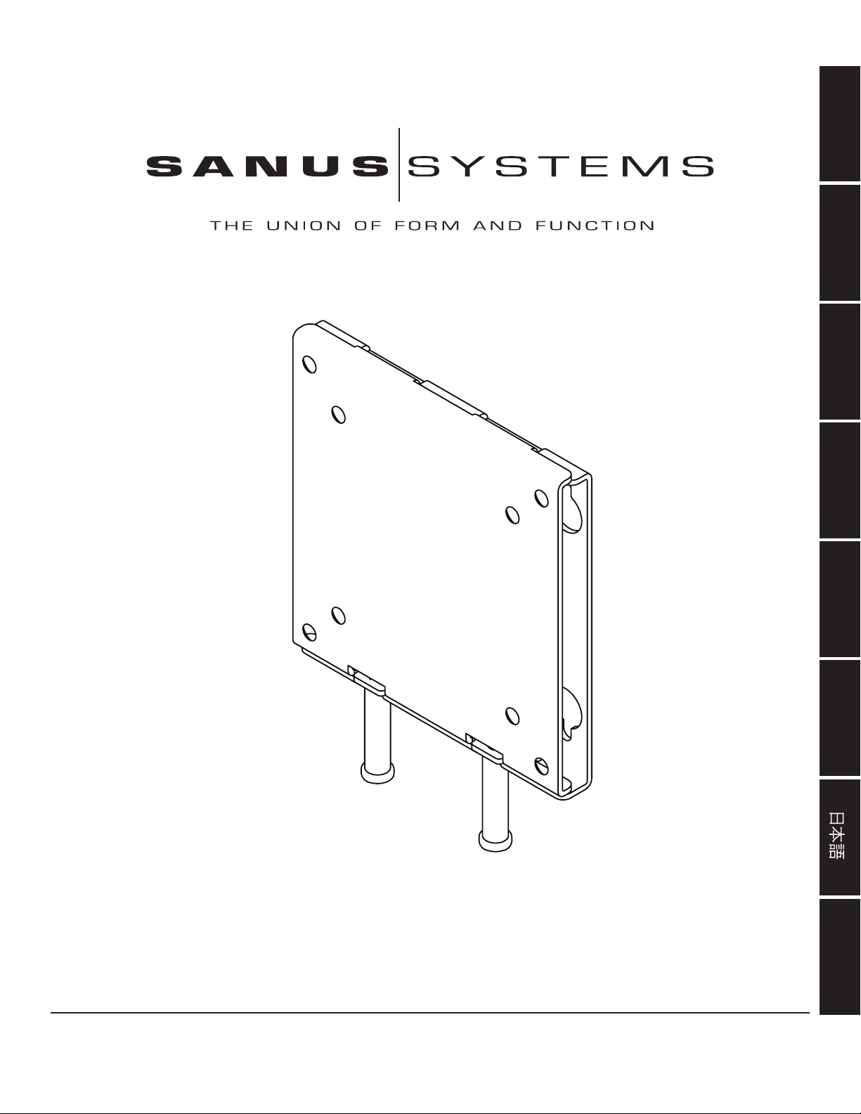
Thank you for choosing a Sanus Systems Vision Mount wall mount. The VMFL1 is designed to mount up to 30” LCD at panel televisions weighing up to 40 lb to a vertical wall. It will allow the television to be just .5” from of the wall.
Safety Warning: If you do not understand these directions, or have any doubts about the safety of the installation, please call a qualied
contractor or contact Sanus at 800.359.5520 or www.sanus.com. Check carefully to make sure that there are no missing or defective
parts. Our customer service representatives can quickly assist you with installation questions and missing or damaged parts. Replacement parts for products purchased through authorized dealers will be shipped directly to you. Never use defective parts. Improper instal-
lation may cause damage or serious injury. Do not use this product for any purpose that is not explicitly specied by Sanus Systems.
Sanus Systems can not be liable for damage or injury caused by incorrect mounting, incorrect assembly, or incorrect use. Please call
Sanus Systems before returning products to the point of purchase.
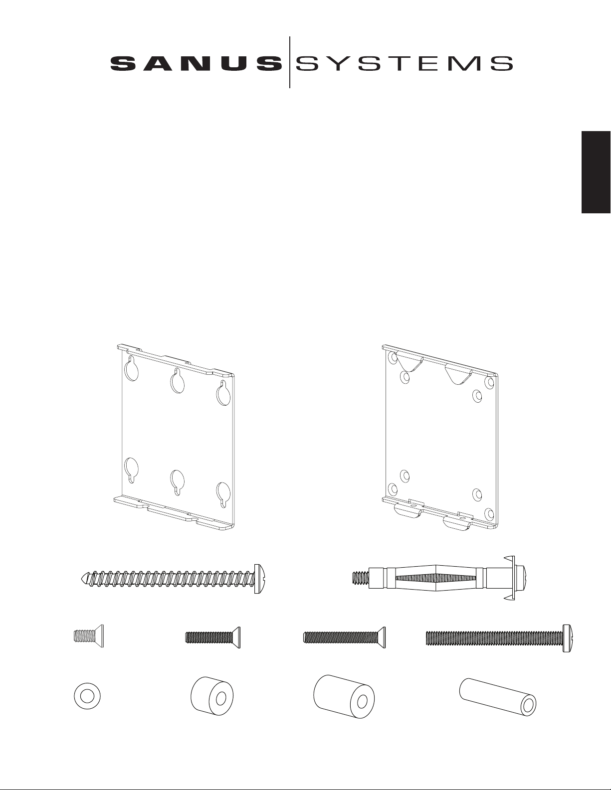
RequireTools: 3/8 drill bit, phillips screw driver
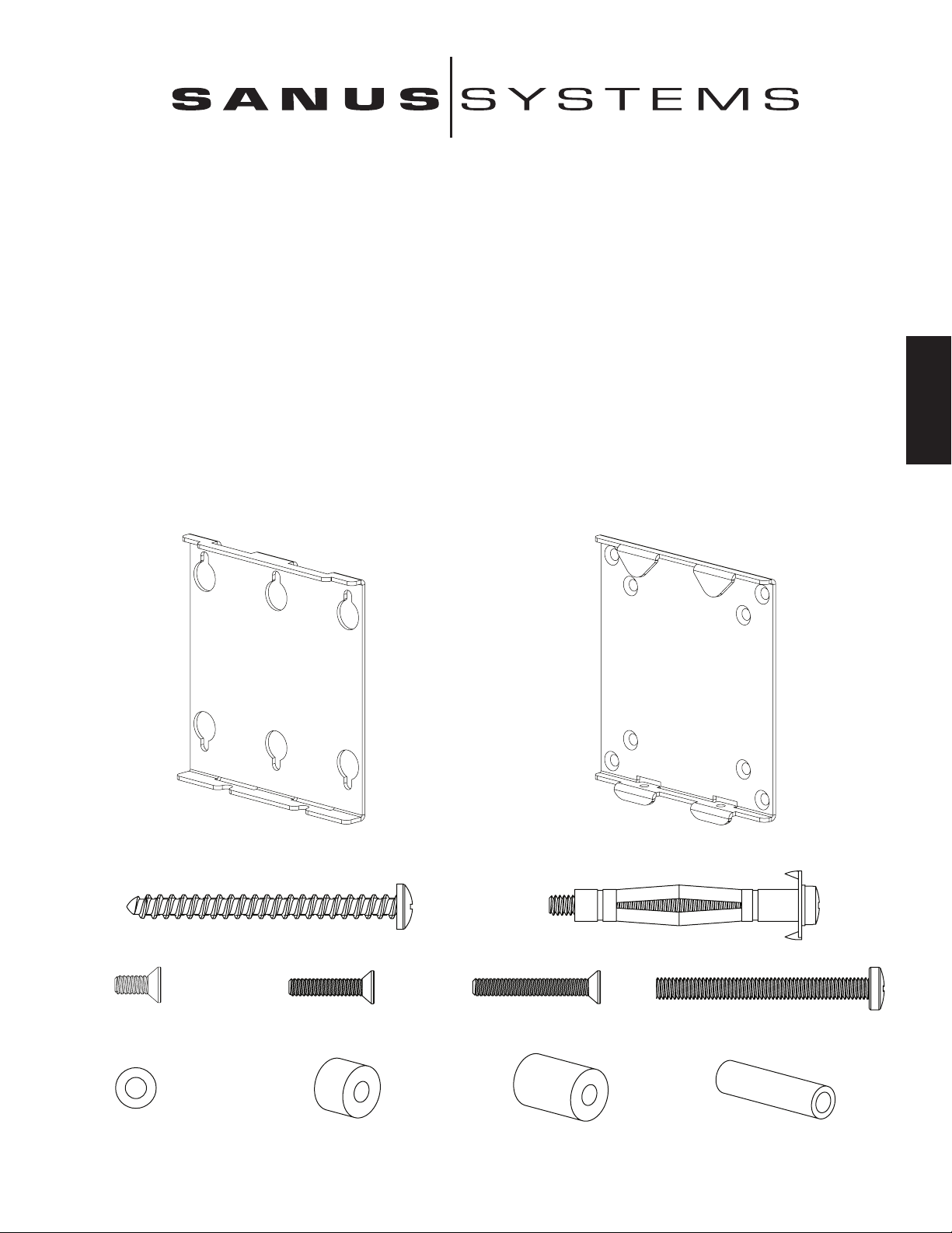
Supplied Parts and Hardware: Some parts not shown as actual size*
ENGLISH
(1) Wall Plate - a* (1) Monitor Bracket - b*
(2) Lag Bolt - c (4) Dry Wall Anchor - d
(4) M4 x 10 mm Bolt - e (4) M4 x 20 mm Bolt - f (4) M4 x 30 mm Bolt - g (2) M5 Locking Bolt - h
(4) M4 Washer - i (4) Small M4 Spacer - j (4) Large M4 Spacer - k (2) M5 Spacer - l
Page 4
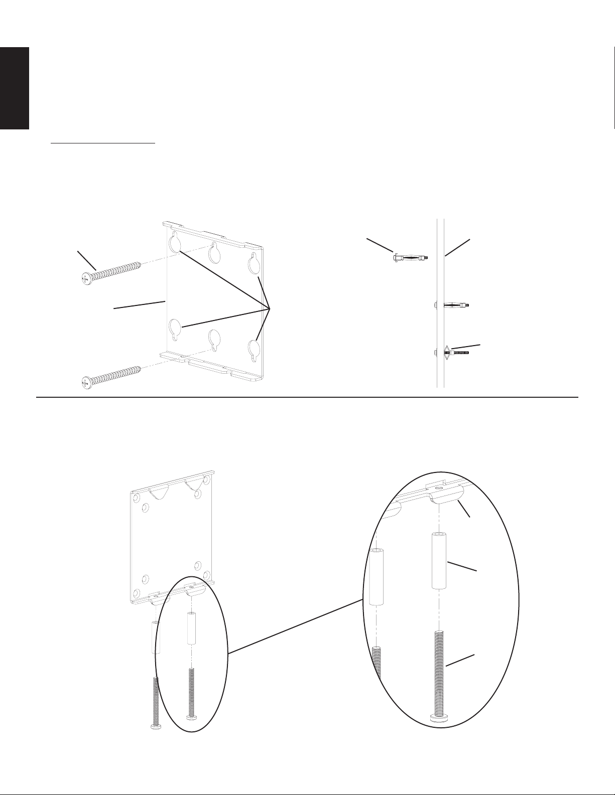
Step 1: Hang Wall Plate
Wood Stud Mounting: First, determine the location of the Wall Plate (a) prior to installation. Use a high quality stud sensor to locate
a stud. Using the Wall Plate as a template and mark two holes in the apporpriate location. Make sure the hole is in the center area of
the stud. Attach the Wall Plate to the wall using two Lag Bolts (c). Make sure the Wall Plate is oriented so the at surface in the center
of the plate is against the wall as shown in Diagram 1a. Proceed to keyhole mount the Wall Plate onto the Lag Bolts. Tighten each Lag
Bolt rmly.
ENGLISH
Drywall Installation: Position the Wall Plate in the desired location on the wall. Using the Wall Plate as a template, mark the location of
the four outer mounting holes. Using a 3/8” drill bit, proceed to drill a 3/8” pilot hole in each marked location. Install a Dry Wall Anchor
(d) in one of the pilot holes and tighten the anchor bolt until it is fully seated. See Diagram 1b. Loosen the anchor bolt approximately
1/4” and repeat process for the three additional pilot holes. Once Wall Plate is keyhole mounted onto the wall, proceed to tighten all 4
anchor bolts rmly.
Note: For Drywall Installations, make sure the Washer is inbetween the head of the anchor bolt and the Wall Plate.
Diagram 1a Diagram 1b
d drill 3/8” pilot hole
c
a drywall mounting holes
tighten anchor bolt until
the Anchor is pulled up
against the wall
Step 2: Install M5 Locking Bolts
Insert each M5 Locking Bolt (h) through a M5 Spacer (l) and thread it into the appropriate hole in the Monitor Bracket (b) as seen in the
Detailed View of Diagram 2. Thread the M5 Locking Bolt into the Monitor Bracket just enough to engage the threading.
Diagram 2 Detailed View
b
l
h
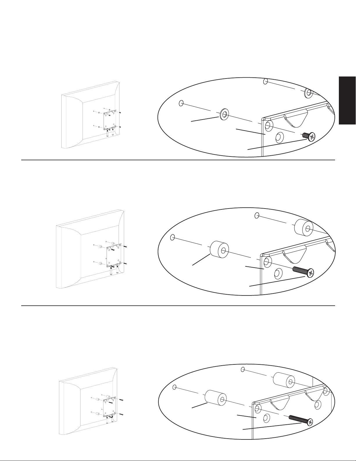
Note: For TVs that have a at back see Step 3. For TVs that have a recessed hole pattern, see Step 4. For TVs that have a deeply
recessed hole pattern, see Step 5.
Page 5
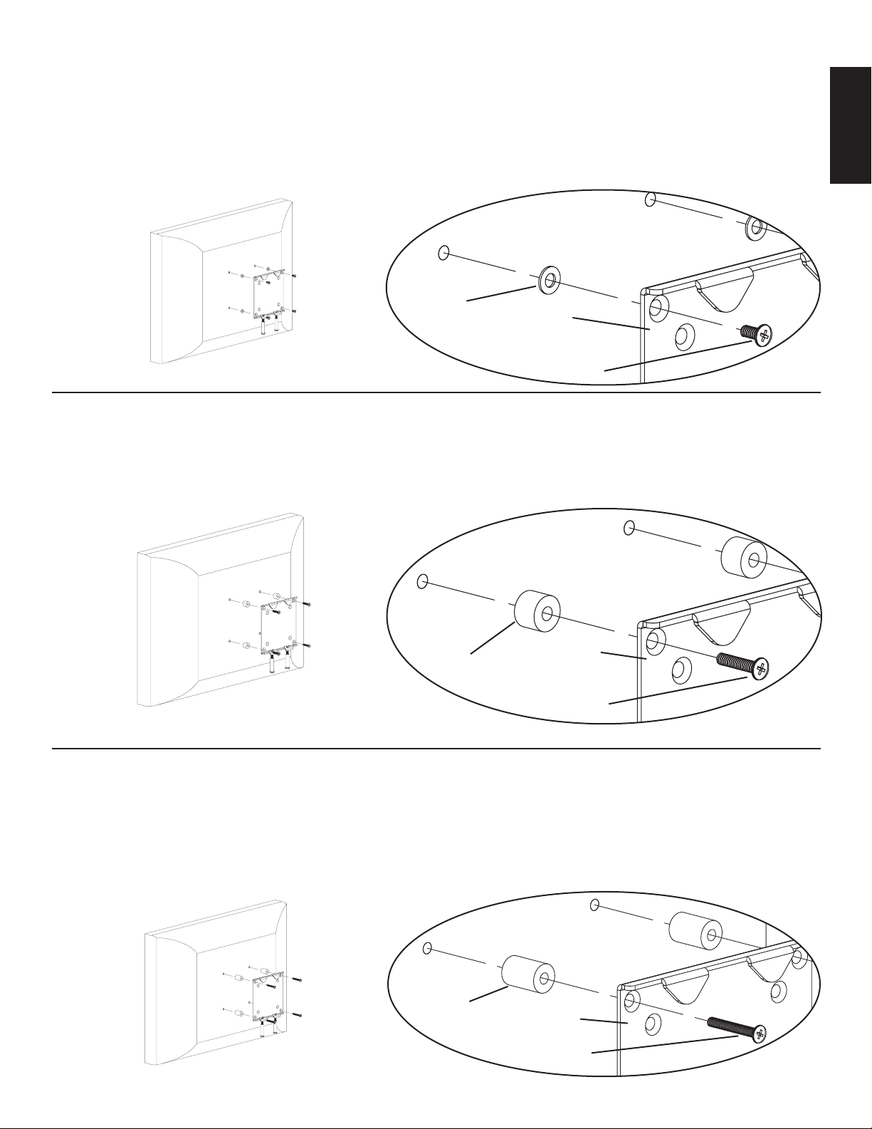
Step 3: Attach Monitor Bracket to at back TV
To attach the Monitor Bracket (b) to the TV, simply insert a M4 x 10 mm Bolt (e) through the countersunk hole in the Monitor Bracket,
the M4 Washer (i) and thread it into the TV. Repeat process until all 4 bolts are secured to the TV. See the Detailed View of Diagram 3
for assistance. Proceed to tighten each bolt with a phillips screw driver.
Note: For installations where the hole pattern is recessed into the back of the TV, see Step 3 or Step 4.
Diagram 3 Detailed View
i
b
e
Step 4: Attach Monitor Bracket to a TV with a recessed hole pattern
To attach the Monitor Bracket (b) to the TV, simply insert a M4 x 20 mm Bolt (f) through the countersunk hole in the Monitor Bracket,
the Small M4 Spacer (j) and thread it into the TV. Repeat process until all 4 bolts are secured to the TV. See the Detailed View of Diagram
4 for assistance. Proceed to tighten each bolt with a phillips screw driver
ENGLISH
Diagram 4 Detailed View
j b
f
Step 5: Attach Monitor Bracket to a TV with a deeply recessed hole pattern
To attach the Monitor Bracket (b) to the TV, simply insert a M4 x 30 mm Bolt (g) through the countersunk hole in the Monitor Bracket,
the Large M4 Spacer (k) and thread it into the TV. Repeat process until all 4 bolts are secured to the TV. See the Detailed View of Diagram 5 for assistance. Proceed to tighten each bolt with a phillips screw driver.
Diagram 5 Detailed View
k
b
g
Page 6
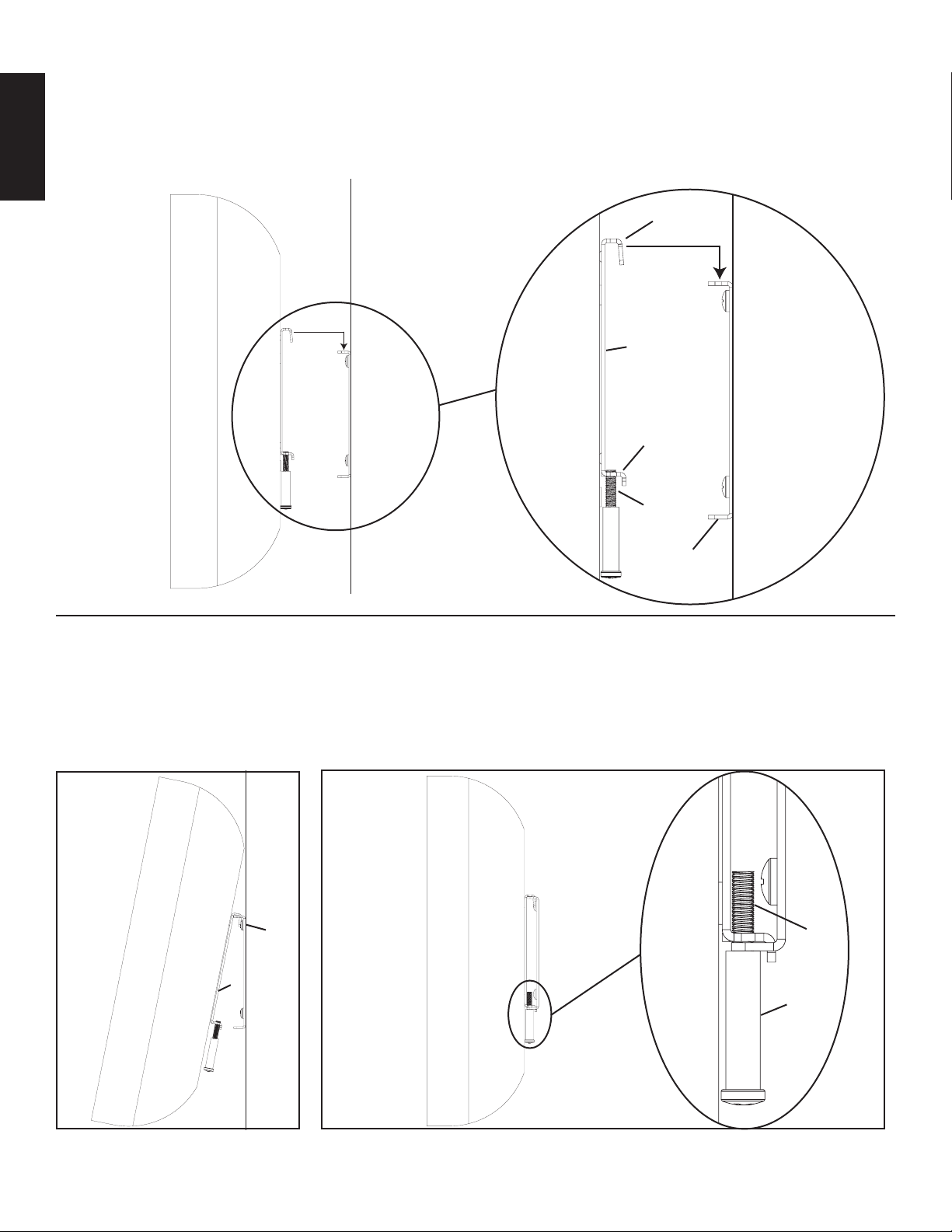
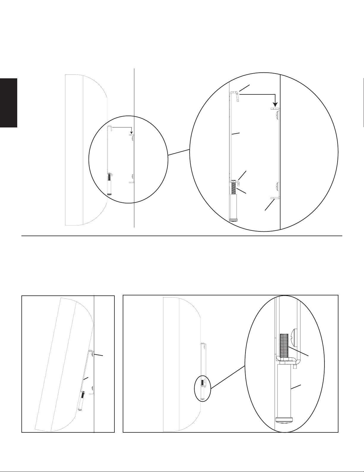
Step 6: Attach Monitor Bracket to Wall Plate
Lift the TV up so the two hooks on the Monitor Bracket (b) align with the slits on the top of the Wall Plate (a). See the Detailed View of
Diagram 6 for assistance. Ensure the Monitor Bracket and Wall Plate are secured together by the top two hooks.
Note: Do not tighten Locking Bolts (h) at this point!
Diagram 6 Detailed View
ENGLISH
hook
b
wall
tab
h
a
Step 7: Cable hook up and lock Monitor Bracket to Wall Plate
To allow for greater space between the wall and your display to install cables, allow the display to hang from the two top hooks on the
Monitor Bracket (b) with the bottom tabs free to move as shown in Diagram 7a. Once all cables are installed, make sure the top two
hooks and the bottom two tabs are engaged with the wall plate. See the Detailed View of Diagram 7b. Proceed to tighten the M5 Locking
Bolt (h) so the Monitor Bracket is secured to the Wall Plate.
Diagram 7a Diagram 7b Detailed View
a h
TV
b
l
wall
Page 7
Instrucciones de armado del modelo: VMFL1
Gracias por elegir el soporte de pared VisionMount™ de Sanus Systems. El modelo VMFL1 ha sido diseñado para montar televisores
con pantalla plana de 30 pulgadas con un peso de hasta 18,2 kg en una pared vertical. Este modelo permite fijar el televisor a apenas
1,3 cm de la pared.
Advertencia de seguridad: Si no entiende estas instrucciones o si tiene alguna duda con respecto a la seguridad de la instalación, llame
a un contratista calicado o llámenos al 800.359.5520 (en EE.UU.) o al 31 (0) 20 5708938 (en Europa). También nos puede visitar en
nuestro sitio www.sanus.com. Revise cuidadosamente para asegurarse de que no hayan piezas faltantes o defectuosas. Nuestros representantes del servicio al cliente pueden ayudarle a responder sus preguntas sobre la instalación o con respecto a las piezas faltantes
o defectuosas. Las piezas de repuesto para los productos comprados a través de un distribuidor autorizado se enviarán directamente a
usted. Nunca use piezas que presenten algún defecto. La instalación incorrecta puede provocar daño o lesiones graves. No use este
producto para nes que no estén especicados explícitamente por Sanus Systems. Sanus Systems no se hace responsable de los daños
ni de las lesiones causadas por el montaje, armado o uso incorrectos. Sírvase llamar a Sanus Systems antes de devolver los productos al
punto de compra.
Herramientas requeridas: Broca de 3/8 pulgada, destornillador phillips
Piezas y tornillería suministradas: Algunas piezas no se muestran del tamaño real*
ESPAÑOL
(1) Placa adaptadora - a* (1) Soporte de monitor - b*
(2) Tirafondo - c (4) Anclaje para panel de yeso - d
(4) Perno M4 x 10 mm - e (4) Perno M4 x 20 mm - f (4) Perno M4 x 30 mm - g (2) Perno de bloqueo M5 - h
(4) Arandela de seguridad M4 - i (4) Espaciador M4 pequeño - j (4) Espaciador M4 grande - k (2) Espaciador M5 - l
Page 8
Paso 1: Colgar la placa de pared
Montaje sobre pie derecho de madera: Primero, determinar la ubicación de la placa de pared (a) antes de la instalación. Utilizar un
detector de vigas de alta calidad para localizar el pie derecho. Utilizar la placa de pared como una plantilla y marcar dos agujeros en la
ubicación correcta. Asegurarse de que el agujero quede bien centrado en el pie derecho. Conectar la placa en la pared con dos tirafondos
(c). Asegurarse que la placa de pared esté orientada de manera que la supercie plana del centro de la placa quede contra la pared, como se
ilustra en el diagrama 1a. Proceder a montar la placa de pared en los tirafondos. Apretar rmemente cada uno de los tirafondos.
Instalación sobre un panel de yeso: Colocar la placa de pared en la ubicación deseada en la pared. Utilizar la placa de pared como una
plantilla y marcar la ubicación de los cuatro agujeros de montaje exteriores. Con una broca de 3/8 pulgada, perforar un agujero piloto de
1 cm en cada punto marcado. Instalar un anclaje (d) en uno de los agujeros piloto y apretar el perno hasta que quede bien asentado en el
anclaje. Ver el diagrama 1b. Aojar el perno de anclaje aproximadamente 0,6 cm y repetir el proceso en los tres agujeros piloto adicionales.
Una vez que la placa se monta en los agujeros de la pared, proceder a apretar rmemente los 4 pernos de anclaje.
Nota: Para instalaciones sobre paneles de yeso, asegurarse de que la arandela esté entre la cabeza del perno de anclaje y la placa de pared.
ESPAÑOL
Diagrama 1a Diagrama 1b
d perforar un agujero
c de 1 cm
a agujeros de montaje
en panel de yeso
apretar el perno hasta
que quede bien
insertado
en el anclaje
contra la pared
Paso 2: Instalar los pernos de bloqueo M5
Pasar cada perno de bloqueo M5 (h) a través de un espaciador M5 (l) e insertarlo en el agujero correspondiente en el soporte de monitor
(b), como se muestra en la vista detallada del diagrama 2. Enroscar el perno de bloqueo M5 en el soporte de monitor sólo lo suciente
para engranar el inicio de la rosca.
Diagrama 2 Vista detallada
b
l
h
Nota: Para los televisores que tienen la parte trasera plana, ver el paso 3. Para los televisores que tienen un patrón de agujeros, ver el paso 4.
Para los televisores que tienen un patrón de agujeros profundos, ver el paso 5.
Page 9
Paso 3: Conectar el soporte de monitor al televisor con la parte trasera plana
Para conectar el soporte de monitor (b) en el televisor, simplemente pasar un perno M4 x 10 mm (e) a través del agujero contrataladrado
del soporte de monitor, la arandela M4 (i) e insertarlo en el televisor. Repetir el proceso hasta que los 4 pernos queden bien asegurados
en el televisor. Ver la vista detallada del diagrama 3 para más ayuda. Proceder a apretar los pernos con un destornillador phillips.
Nota: Para las instalaciones en las que el patrón de agujeros se encuentra hendido en la parte trasera del televisor, ver el paso 3 ó 4.
Diagrama 3 Vista detallada
i
b
e
Paso 4: Conectar el soporte de monitor a un televisor con un patrón de agujeros hendidos
Para conectar el soporte de monitor (b) en el televisor, simplemente pasar un perno M4 x 20 mm (f) a través del agujero contrataladrado del
soporte de monitor, el espaciador M4 pequeño (j) e insertarlo en el televisor. Repetir el proceso hasta que los 4 pernos queden bien asegura-
dos en el televisor. Ver la vista detallada del diagrama 4 para más ayuda. Proceder a apretar los pernos con un destornillador phillips.
ESPAÑOL
Diagrama 4 Vista detallada
j b
f
Paso 5: Conectar el soporte de monitor a un televisor con un patrón de agujeros profundos
Para conectar el soporte de monitor (b) en el televisor, simplemente pasar un perno M4 x 30 mm (g) a través del agujero contrataladrado del
soporte de monitor, el espaciador M4 grande (k) e insertarlo en el televisor. Repetir el proceso hasta que los 4 pernos queden bien asegurados
en el televisor. Ver la vista detallada del diagrama 5 para más ayuda. Proceder a apretar los pernos con un destornillador phillips.
Diagrama 5 Vista detallada
k
b
g
Page 10
Paso 6: Conectar el soporte de monitor a la placa de pared
Levantar el televisor de manera que los dos ganchos que se encuentran en el soporte de monitor (b) se alineen con las aberturas en la
parte superior de la placa de pared (a). Ver la vista detallada del diagrama 6 para más ayuda. Asegurarse de que el soporte de monitor y
la placa de pared estén bien asegurados con los dos ganchos superiores.
Nota: ¡No apretar los pernos de bloqueo (h) en este momento!
Diagrama 6 Vista detallada
gancho
ESPAÑOL
b
pared
pestaña
h
a
Paso 7: Conexión de cables y bloqueo del soporte de monitor en la placa de pared
Para permitir más espacio entre la pared y el mazo de cables, dejar que el mazo cuelgue de los dos ganchos superiores del soporte de
monitor (b) con las pestañas inferiores libres de movimiento, como se ilustra en el diagrama 7a. Una vez que todos los cables estén insta-
lados, asegurarse de que los dos ganchos superiores y las dos pestañas inferiores queden enganchadas con la placa de pared. Ver la vista
detallada del diagrama 7b. Proceder a apretar el perno de bloqueo M5 (h) de manera que el soporte de monitor quede bien asegurado a
la placa de pared.
Diagrama 7a Diagrama 7b Vista detallada
a h
TV
b
l
pared
Page 11
Montageanweisungen für das Modell: VMFL1
Wir freuen uns, dass Sie sich für eine VisionMount™-Wandhalterung von Sanus Systems entschieden haben. Das Gerät VMFL1 ist für
die Montage von LCD-Flachbildfernsehern mit einer Bildschirmdiagonale von 30 Zoll und einem Gewicht von maximal 18,2 kg an einer
vertikalen Wand vorgesehen. Der Fernseher kann in einem Abstand von nur 1,3 cm von der Wand montiert werden.
Sicherheitshinweis: Wenn Sie diese Anweisungen nicht verstehen oder Zweifel an der Sicherheit der Montage haben, rufen Sie einen
Fachmann an oder kontaktieren Sie Sanus Systems telefonisch unter +1-800-359-5520 (USA) oder +31-(0)20-570-8938 (Europa). Oder
besuchen Sie uns im Internet unter www.sanus.com. Überprüfen Sie die Zubehörteile sorgfältig, um sicherzugehen, dass keine Teile fehlen
oder beschädigt sind. Unsere Kundendienstmitarbeiter können Ihnen bei Fragen zur Montage und bei fehlenden oder beschädigten Teilen
schnell weiterhelfen. Ersatzteile für bei autorisierten Fachhändlern gekaufte Sanus-Produkte werden direkt an Ihre Adresse versendet.
Verwenden Sie niemals beschädigte Teile! Unsachgemäße Montage kann Schäden am Gerät und schwere Verletzungen hervorrufen!
Verwenden Sie das Produkt nicht für andere als von Sanus Systems explizit genannte Zwecke. Sanus Systems haftet nicht für Schäden oder
Verletzungen, die durch unsachgemäße Montage, fehlerhaften Zusammenbau oder unsachgemäße Nutzung entstehen. Bitte rufen Sie Sanus
Systems an, bevor Sie Produkte beim Händler reklamieren.
Erforderliche Werkzeuge: Bohrer 3/8 Zoll, Kreuzschlitzschraubendreher
Mitgelieferte Teile und Zubehör: Mit * markierte Teile sind verkleinert dargestellt.
DEUTSCH
(1) Wandplatte – a* (1) Monitorklammer – b*
(2) Holzschraube – c (4) Trockenwanddübel – d
(4) Schraube M4 x 10 mm – e (4) Schraube M4 x 20 mm – f (4) Schraube M4 x 30 mm – g (2) Sicherungsschraube M5 – h
(4) Unterlegscheibe M4 – i (4) Kleines Distanzstück M4 – j (4) Großes Distanzstück M4/M5 – k (2) Distanzstück M5 – l
Page 12

Schritt 1: Anhängen der Wandplatte
Montage an einem Holzbalkenträger: Zunächst die Lage der Wandplatte (a) vor der Montage ermitteln. Mit einem hochwertigen Sensor
einen Träger suchen. Die Wandplatte als Schablone verwenden und die Positionen der beiden Bohrungen markieren. Die Bohrung muss
sich in der Mitte des Holzbalkenträgers benden. Die Wandplatte mit zwei Holzschrauben (c) an der Wand montieren. Die Wandplatte
muss so ausgerichtet sein, dass die ache Fläche in der Mitte der Platte wie in Abbildung 1a zur Wand zeigt. Die Wandplatte über die
Holzschrauben hängen. Die Holzschrauben festziehen.
Trockenwandmontage: Die Wandplatte an der gewünschten Stelle der Wand anordnen. Die Wandplatte als Schablone zur Markierung
der vier äußeren Montagebohrungen verwenden. Mit einem Bohrer 3/8 Zoll eine Bohrung 1 cm für jede markierte Position vorbohren.
Einen Trockenwanddübel (d) in jede der Bohrungen einsetzen und die Dübelschraube festziehen, bis sie richtig sitzt. Siehe Abbildung
1b. Die Dübelschraube etwa 0,6 cm herausdrehen und die Schritte für die drei anderen vorgebohrten Löcher wiederholen. Sobald die
Wandplatte an der Wand montiert ist, die 4 Dübelschrauben festziehen.
Hinweis: Bei Trockenwandmontage darauf achten, dass die Unterlegscheibe sich zwischen dem Kopf der Dübelschraube und
der Wandplatte bendet.
Abbildung 1a Abbildung 1b
d Vorbohren mit einem
c Bohrer 3/8 Zoll
DEUTSCH
a Bohrungen für die Trockenwandmontage
Die Dübelschraube
festziehen, bis
der Dübel von innen
gegen die Wand
gedrückt wird.
Schritt 2: Eindrehen der Sicherungsschrauben M5
In jede der entsprechenden Bohrungen der Monitorklammer (b) wie in der Detailansicht von Abbildung 2 eine Sicherungsschraube M5 (h) mit
einem Distanzstück M5 (l) eindrehen. Die Sicherungsschraube M5 so weit in die Monitorklammer eindrehen, dass sie in dem Gewinde sitzt.
Abbildung 2 Detailansicht
b
l
h
Hinweis: Bei Fernsehern mit einer achen Rückseite entsprechend Schritt 3 verfahren. Bei Fernsehern mit einer vertieften Bohrung an der Rückseite
entsprechend Schritt 4 verfahren. Bei Fernsehern mit einer sehr stark vertieften Bohrung an der Rückseite entsprechend Schritt 5 verfahren.
Page 13

Schritt 3: Montage der Monitorklammer an einem Fernseher mit acher Rückseite
Zum Anbau der Monitorklammer (b) am Fernsehgerät eine Schraube M4 × 10 mm (e) durch die versenkte Bohrung in der Monitorklammer
und die Unterlegscheibe M4 (i) stecken und in den Fernseher eindrehen. Die Arbeitsschritte wiederholen, bis alle 4 Schrauben im
Fernseher sitzen. Siehe dazu Detailansicht in Abbildung 3. Jede Schraube mit einem Kreuzschlitzschraubendreher festziehen.
Hinweis: Bei Montagen von Fernsehern mit vertieften Bohrungen an der Rückseite, entsprechend Schritt 3 oder 4 verfahren.
Abbildung 3 Detailansicht
i
b
e
Schritt 4: Montage der Monitorklammer an einem Fernseher mit vertieften Bohrungen
Zum Anbau der Monitorklammer (b) am Fernsehgerät eine Schraube M4 × 20 mm (f) durch die versenkte Bohrung in der Monitorklammer
und das kleine Distanzstück (j) stecken und in den Fernseher eindrehen. Die Arbeitsschritte wiederholen, bis alle 4 Schrauben im
Fernseher sitzen. Siehe dazu Detailansicht in Abbildung 4. Jede Schraube mit einem Kreuzschlitzschraubendreher festziehen.
DEUTSCH
Abbildung 4 Detailansicht
j b
f
Schritt 5: Montage der Monitorklammer an einem Fernseher mit sehr stark vertieften Bohrungen
Zum Anbau der Monitorklammer (b) am Fernsehgerät eine Schraube M4 × 30 mm (g) durch die versenkte Bohrung in der Monitorklammer
und das große Distanzstück (k) stecken und in den Fernseher eindrehen. Die Arbeitsschritte wiederholen, bis alle 4 Schrauben im
Fernseher sitzen. Siehe dazu Detailansicht in Abbildung 5. Jede Schraube mit einem Kreuzschlitzschraubendreher festziehen.
Abbildung 5 Detailansicht
k
b
g
Page 14

Schritt 6: Montage der Monitorklammer an der Wandplatte
Den Fernseher bis zu den beiden Haken der Monitorklammer (b) anheben und auf die Schlitze an der Oberseite der Wandplatte (a) ausrichten.
Siehe dazu Detailansicht in Abbildung 6. Die Monitorklammer und die Wandplatte müssen durch die beiden oberen Haken gesichert sein.
Hinweis: Die Sicherungsschrauben (h) jetzt noch nicht festziehen!
Abbildung 6 Detailansicht
Haken
b
Wand
Nase
DEUTSCH
h
a
Schritt 7: Sicherung des Kabels und Fixieren der Monitorklammer an der Wandplatte
Um mehr Platz zwischen der Wand und dem Fernseher zur Verlegung der Kabel zu haben, kann der Fernseher an den beiden oberen
Haken der Monitorklammer (b) hängen, während die unteren Nasen sich wie in Abbildung 7a frei bewegen können. Sobald alle Kabel
montiert sind, die beiden oberen Haken und die beiden unteren Nasen in die Wandplatte einrasten lassen. Siehe Detailansicht von
Abbildung 7b. Anschließend die Sicherungsschraube M5 (h) festziehen, so dass die Monitorklammer an der Wandplatte xiert ist.
Abbildung 7a Abbildung 7b Detailansicht
a h
Fernseher
b
l
Wand
Page 15

Instructions d’assemblage pour le modèle : VMFL1
Nous vous remercions d’avoir choisi un montant mural VisionMount™ de Sanus Systems. Le VMFL1 est conçu pour soutenir au
mur des téléviseurs LCD à panneau plat allant jusqu’à 30 pouces et d’un poids maximal de 18,2 kg. Il permettra de placer le téléviseur à
1,3 cm du mur seulement.
Précautions de sécurité : Si vous ne comprenez pas ces instructions ou si vous avez un doute quant à la sécurité de cette installation, veuillez
faire appel à un technicien qualié ou communiquez avec Sanus en composant le 1-800-359-5520 (aux É.-U.), ou le 31 (0) 20 5708938 (pour
l’Europe). Vous pouvez aussi allez sur notre site Web au www.sanus.com. Vériez soigneusement qu’il n’y a aucune pièce manquante ou
défectueuse. Les représentants de notre service à la clientèle peuvent répondre rapidement à toute question concernant l’installation ou les
pièces manquantes ou endommagées. Les pièces de rechange de produits achetés auprès de distributeurs agréés vous seront livrées directement.
N’utilisez jamais de pièces défectueuses. Une installation incorrecte peut entraîner des dommages ou des blessures graves. Ce produit ne doit
être utilisé que pour des usages explicitement spéciés par Sanus Systems. Sanus Systems ne pourra être tenu responsable de dommages ou de
blessures dus à un montage incorrect, à un assemblage incorrect ou à un usage incorrect. Veuillez contacter Sanus Systems avant de retourner
les produits au lieu de vente.
Outils nécessaires : Mèche de 3/8 pouce, tournevis cruciforme
Pièces et matériel fournis : Certaines pièces ne sont pas illustrées grandeur réelle*
(1) Plaque murale - a* (1) Support du moniteur - b*
FRANÇAIS
(2) Tire-fond - c (4) Cheville pour cloison sèche - d
(4) Boulon M4 x 10 mm - e (4) Boulon M4 x 20 mm - f (4) Boulon M4 x 30 mm - g (2) Boulon de blocage M5 - h
(4) Rondelle M4 - i (4) Petite rondelle M4 - j (4) Grande entretoise M4 - k (2) Entretoise M5 - l
Page 16

Etape 1 : Suspension de la plaque murale
Montage sur ossature de bois : Commencez par déterminer l’emplacement de la plaque murale (a) avant l’installation. Servez-vous d’un
détecteur de montants de haute qualité pour repérer un montant. Servez-vous de la plaque murale comme modèle an de marquer deux
emplacements de trous à l’endroit approprié. Assurez-vous que le trou se trouve bien dans la zone centrale du montant. Fixez la plaque murale
sur le mur à l’aide des deux tire-fonds (c). Assurez-vous que la plaque murale est orientée de façon à ce que la surface plane au centre de la
plaque soit contre le mur tel qu’indiqué sur le schéma 1a. Continuez à faire entrer la plaque murale dans les trous de serrure sur les tire-fonds.
Serrez tous les tire-fonds fermement.
Installation sur cloisons sèches : Positionnez la plaque murale à l’emplacement désiré sur le mur. En vous servant de la plaque murale comme
modèle, marquez l’emplacement des quatre trous de montage externes. Avec une mèche de 3/8 pouce, percez un avant-trou de 1 cm sur tous les
emplacements marqués. Installez une cheville pour cloison sèche (d) dans l’un des avant-trous et serrez le boulon d’ancrage jusqu’à ce qu’il soit
complètement logé. Reportez-vous au schéma 1b. Desserrez le boulon d’ancrage d’environ 0,6 cm et recommencez le processus pour les trois
avant-trous supplémentaires. Une fois la plaque murale montée sur le mur, serrez les 4 boulons d’ancrage fermement.
Remarque : Pour les installations sur cloisons sèches, veillez à ce que la rondelle se trouve entre la tête du boulon d’ancrage et la plaque murale.
Schéma 1a Schéma 1b
d percez un avant-trou
c de 1 cm
a trous pour cloison sèche
serrez le boulon
d’ancrage jusqu’à
ce que la cheville soit
FRANÇAIS
relevée
contre le mur
Etape 2 : Installation des boulons de blocage M5
Insérez chacun des boulons de blocage M5 (h) dans une entretoise M5 (l) et vissez-les dans le trou approprié du support du moniteur (b), tel
qu’illustré sur la vue détaillée du schéma 2. Vissez le boulon de blocage M5 dans le support du moniteur, juste assez pour engager le letage.
Schéma 2 Vue détaillée
b
l
h
Remarque : Pour les téléviseurs à panneau arrière plat, reportez-vous à l’étape 3. Pour les téléviseurs dotés d’une conguration de trous de montage en
retrait, reportez-vous à l’étape 4. Pour les téléviseurs dotés d’une conguration de trous de montage profondément en retrait, reportez-vous à l’étape 5.
Page 17

Etape 3 : Fixation du support du moniteur sur un téléviseur à panneau arrière plat
Pour xer le support du moniteur (b) au téléviseur, il vous suft d’insérer un boulon M4 x 10 mm (e) dans le trou fraisé du support du moniteur
et la rondelle M4 (i), et de le visser dans le téléviseur. Recommencez le processus jusqu’à ce que les 4 boulons soient xés au téléviseur.
Reportez vous à la vue détaillée du schéma 3 si vous avez besoin d’aide. Resserrez bien tous les boulons à l’aide d’un tournevis cruciforme.
Remarque : Pour les installations où la conguration de trous de montage est en retrait à l’arrière du téléviseur, reportez-vous à l’étape 3 ou 4.
Schéma 3 Vue détaillée
i
b
e
Etape 4 : Fixation du support du moniteur à un téléviseur doté d’une conguration de trous de montage en retrait
Pour xer le support du moniteur (b) au téléviseur, il vous suft d’insérer un boulon M4 x 20 mm (f) dans le trou fraisé du support du
moniteur et la petite rondelle M4 (j) et de le visser dans le téléviseur. Recommencez le processus jusqu’à ce que les 4 boulons soient
xés au téléviseur. Reportez vous à la vue détaillée du schéma 4 si vous avez besoin d’aide. Resserrez bien tous les boulons à l’aide d’un
tournevis cruciforme.
Schéma 4 Vue détaillée
j b
f
Etape 5 : Fixation du support du moniteur à un téléviseur doté d’une conguration de trous de montage profondément en retrait
Pour xer le support du moniteur (b) au téléviseur, il vous suft d’insérer un boulon M4 x 30 mm (g) dans le trou fraisé du support du
moniteur et la grande entretoise M4 (k) et de le visser dans le téléviseur. Recommencez le processus jusqu’à ce que les 4 boulons soient
xés au téléviseur. Reportez vous à la vue détaillée du schéma 5 si vous avez besoin d’aide. Resserrez bien tous les boulons à l’aide d’un
tournevis cruciforme.
FRANÇAIS
Schéma 5 Vue détaillée
k
b
g
Page 18

Etape 6 : Fixation du support du moniteur à la plaque murale
Soulevez le téléviseur de façon à ce que les deux crochets sur le support du moniteur (b) soient alignés avec les fentes sur la partie supérieure
de la plaque murale (a). Reportez vous à la vue détaillée du schéma 6 si vous avez besoin d’aide. Assurez-vous que le support de moniteur et la
plaque murale sont bien xées l’un à l’autre par les deux crochets du haut.
Remarque : Ne serrez pas les boulons de blocage (h) à ce stade !
Schéma 6 Vue détaillée
crochet
b
mur
patte
h
a
FRANÇAIS
Etape 7 : Suspension du câble et verrouillage du support du moniteur sur la plaque murale
Pour laisser un espace plus grand entre le mur et votre écran pour installer les câbles, laissez l’écran pendre des deux crochets du haut sur le
support du moniteur (b) en laissant les pattes inférieures bouger, tel qu’illustré sur le schéma 7a. Une fois que tous les câbles sont installés,
assurez-vous que les deux crochets du haut et les deux pattes du bas sont engagés dans la plaque murale. Reportez-vous à la vue détaillée du
schéma 7b. Serrez le boulon de blocage M5 (h) de façon à ce que le support du moniteur soit bien xé à la plaque murale.
Schéma 7a Schéma 7b Vue détaillée
a h
Téléviseur
b
l
mur
Page 19

L ' U N I O N E D I F O R M A E F U N Z I O N E
Istruzioni di montaggio per il modello: VMFL1
Grazie per aver scelto un sistema di montaggio per parete Sanus Systems VisionMount™. Il VMFL1 è progettato per montare televisori
a pannello piatto LCD no a 30 pollici che pesano no a 18,2 kg su una parete verticale. In tal modo il televisore sarà ad appena 1,3 cm
dalla parete.
Avvertenza sulla sicurezza: se non si comprendono queste istruzioni o si hanno dubbi sulla sicurezza dell’installazione, rivolgersi a
un installatore specializzato o contattare la Sanus al numero verde USA 800.359.5520 o, in Europa, al numero +31 (0) 20 5708938. È
anche possibile visitare il sito www.sanus.com. Controllare attentamente che non vi siano parti mancanti o difettose. Il nostro servizio
di assistenza clienti potrà rispondere rapidamente alle domande relative all’installazione o alle parti mancanti o danneggiate. Le parti di
ricambio per i prodotti acquistati attraverso i rivenditori autorizzati vengono spedite direttamente al cliente. Non utilizzare parti difettose.
L’installazione errata può causare danni o lesioni gravi. Non utilizzare questo prodotto per scopi diversi da quelli specicamente indicati
dalla Sanus Systems. La Sanus Systems non è responsabile di danni o lesioni causati da montaggio o utilizzo non corretti. Chiamare la
Sanus Systems prima di riportare i prodotti al punto vendita.
Strumenti necessari: punta per trapano da 3/8 pollice, un cacciavite Phillips
Parti e minuteria metallica fornite: in gura alcune parti non sono delle dimensioni reali*
(1) piastra per parete - a* (1) staffa per monitor - b*
(2) tirafondo - c (4) ancora per cartongesso - d
(4) M4 da 10 mm - e (4) bullone M4 da 20 mm - f (4) bullone M4 da 30 mm - g (2) bullone di blocco M5 - h
ITALIANO
(4) rondella M4 - i (4) distanziale M4 piccolo - j (4) distanziale M4 grande - k (2) distanziale M5 - l
Page 20

Fase 1: appendere la piastra a parete
Montaggio per travi di legno: innanzitutto, determinare la posizione della piastra per parete (a) prima dell’installazione. Usare un
rilevatore di travi di legno di alta qualità per individuare la trave di legno nella parete. Utilizzare la piastra a parete come maschera per
contrassegnare i due fori nella posizione appropriata. Assicurarsi che il foro si trovi nell’area centrale della trave di legno. Collegare la
piastra per parete alla parete usando i due tirafondi (c). Assicurarsi che la piastra per parete sia orientata in modo che la supercie piatta
al centro della piastra sia contro la parete come mostrato nella Figura 1a. Procedere il montaggio del foro chiave sui tirafondi. Serrare
fermamente ogni tirafondo.
Installazione su cartongesso: posizionare la piastra per parete nella posizione desiderata sulla parete. Utilizzare la piastra a parete come
maschera, contrassegnare la posizione del quarto foro di montaggio esterno. Usando una punta per trapano da 3/8 pollice, procedere a
forare un foro pilota da 1 cm in ogni posizione contrassegnata. Installare un ancoraggio per cartongesso (d) in uno dei fori pilota e serrare
il bullone di ancoraggio no a quando non è completamente inserita. Vedere la Figura 1b. Allentare il bullone di ancoraggio a circa
0,6 cm e ripetere il processo per tre fori pilota aggiuntivi. Una volta che la piastra per parete è un foro chiave montato sulla parete,
procedere a serrare fermamente i 4 bulloni di ancoraggio.
Nota: per installazioni su cartongesso, assicurarsi che la rondella si trovi tra la testa del bullone di ancoraggio e la piastra per parete.
Figura 1a Figura 1b
d forare un foro
c pilota da 1 cm
a fori di montaggio su cartongesso
serrare il bullone di
ancoraggio no a
quando l’ancoraggio
non viene tirato verso
l’alto contro il muro
Fase 2: installare i bulloni di bloccaggio M5
Inserire ogni bullone di bloccaggio M5 (h) attraverso un distanziale M5 (l) e avvitare nel foro appropriato della staffa per monitor
(b) come illustrato nella Vista dettagliata della Figura 2. Avvitare il bullone di blocco M5 nella staffa del monitor quanto basta per
agganciare la lettatura.
ITALIANO
Figura 2 Vista dettagliata
b
l
h
Nota: per una TV con retro piatto, vedere la Fase 3. Per una TV con maschera di foratura inserita, vedere la Fase 4. Per una TV
con maschera di foratura inserita a fondo, vedere la Fase 5.
Page 21

Fase 3: installare la staffa per monitor a TV con retro piatto
Per collegare la staffa del monitor (b) alla TV, è sufciente inserire un bullone M4 da 10 mm (e) attraverso il foro conico nella staffa del
monitor, la rondella M4 (i) e avvitare nella TV. Ripetere l’operazione no a quando tutti e 4 i bulloni non sono ssati nella TV. Vedere
la vista dettagliata della Figura 3 per assistenza. Procedere serrando i bulloni in modo sicuro con un cacciavite Phillips.
Nota: per installazioni in cui la maschera di foratura è inserita sul retro della TV, vedere il passo 3 o il passo 4.
Figura 3 Vista dettagliata
i
b
e
Fase 4: collegare la staffa del monitor alla TV con una maschera di foratura inserita
Per collegare la staffa del monitor (b) alla TV, è sufciente inserire un bullone M4 da 20 mm (f) attraverso il foro conico nella staffa del
monitor, il piccolo distanziale M4 (j) e avvitare nella TV. Ripetere l’operazione no a quando tutti e 4 i bulloni non sono ssati nella TV.
Vedere la vista dettagliata della Figura 4 per assistenza. Procedere serrando i bulloni in modo sicuro con un cacciavite Phillips.
Figura 4 Vista dettagliata
j b
f
Fase 5: collegare la staffa del monitor alla TV con una maschera di foratura inserita a fondo
Per collegare la staffa del monitor (b) alla TV, è sufciente inserire un bullone M4 da 30 mm (g) attraverso il foro conico nella staffa del
monitor, il grande distanziale M4 (k) e avvitare nella TV. Ripetere l’operazione no a quando tutti e 4 i bulloni non sono ssati nella TV.
Vedere la vista dettagliata della Figura 5 per assistenza. Procedere serrando i bulloni in modo sicuro con un cacciavite Phillips.
Figura 5 Vista dettagliata
ITALIANO
k
b
g
Page 22

Fase 6: installare la staffa per monitor alla piastra per parete
Sollevare la TV verso l’alto in modo che i due ganci sulla staffa del monitor (b) siano allineati con la parte superiore della piastra per
parete (a). Vedere la vista dettagliata della Figura 6 per assistenza. Assicurarsi che la staffa per monitor e la piastra per parete siano ssate
insieme con i due ganci superiori.
Nota: non serrare i bulloni di blocco (h) in questo momento.
Figura 6 Vista dettagliata
gancio
b
parete
linguetta
h
a
Fase 7: aggancio del cavo e blocco della staffa per monitor alla piastra per parete
Per avere più spazio tra la parete e il display per installare i cavi, lasciare appeso il display dai due ganci superiori sulla staffa per monitor
(b) con le linguette inferiori libere di spostarsi come mostrato nella Figura 7a. Una volta installati i cavi, assicurarsi che i due ganci
superiori e le due linguette inferiori siano agganciate con la piastra per parete. Vedere la vista dettagliata della Figura 7b. Procedere a
ITALIANO
serrare il bullone di blocco M5 (h) in modo che la staffa del monitor sia ssata alla piastra per parete.
Figura 7a Figura 7b Vista dettagliata
a h
TV
b
l
parete
Page 23

Инструкция по сборке крепления модели VMFL1
Благодарим Вас за приобретение настенного крепления Sanus Systems VisionMount™. Крепление VMFL1 предназначено
для установки плоскопанельных телевизоров с диагональю до 30 дюймов, весом до 18,2 кг на вертикальные стены. Крепление
обеспечивает расстояние между телевизором и стеной всего 1,3 cм.
Внимание! Если Вам непонятны приведенные ниже инструкции, или если возникают любые сомнения по поводу безопасности
использования установленного устройства, обратитесь к квалифицированному специалисту или в компанию Sanus по телефону
800-359-5520 (США) или 31 (0) 20 5708938 (Европа). Вы также можете посетить наш веб-сайт www.sanus.com. Тщательно проверьте
наличие всех деталей и отсутствие заводского брака. Сотрудники нашей службы работы с покупателями незамедлительно
помогут Вам решить все вопросы, связанные с установкой устройства, а также с недостающими либо поврежденными деталями.
Запасные части к изделиям компании Sanus, приобретенным через уполномоченных агентов по продаже, будут доставлены
непосредственно по указанному Вами адресу. Не используйте бракованные детали. Неправильная установка устройства может
привести к травмированию людей и порче имущества. Это изделие может применяться исключительно в целях, прямо указанных
производителем. Компания Sanus Systems не несет ответственности за вред здоровью или материальный ущерб, причиненный
вследствие неправильной сборки, монтажа и эксплуатации устройства. Решив вернуть изделие в магазин, где Вы его приобрели,
обратитесь, пожалуйста, сначала в компанию Sanus Systems.
Необходимые инструменты: сверло 3/8 дюйма, крестообразная отвертка.
Детали устройства и крепежные детали: Изображены в масштабе*
Настенная крепежная пластина (a*) – 1 шт. Крепежная скоба для монитора (b*) – 1 шт.
Шуруп под ключ (c) – 2 шт. Дюбель для гипсокартона (d) – 4 шт.
Винт M4 x 10 мм (e) – 4 шт. Винт M4 x 20 мм (f) – 4 шт. Винт M4 x 30 мм (g) – 4 шт. Фиксирующий винт M5 (h) – 2 шт.
Шайба M4 Шайба установочная малая M4 Шайба установочная большая M4 Шайба установочная М5
(i) – 4 шт. (j) – 4 шт. (k) – 4 шт. (l) – 2 шт.
PYCCKO
Page 24

Шаг 1. Прикрепление настенной крепежной пластины
Монтаж на деревянной стойке каркасной стены: Перед установкой определите местонахождение настенной пластины (a). Для
определения местонахождения деревянной стойки следует использовать высокочувствительный датчик. Используя настенную
крепежную пластину как шаблон, отметьте соответствующие места для двух отверстий. Убедитесь, что отверстие сделано по
центру стойки. Прикрепите настенную крепежную пластину к стене, используя два шурупа под ключ (c). Убедитесь, что настенная
крепежная пластина повернута плоской поверхностью в центре к стене, как показано на рисунке 1а. Насадите настенную крепежную
пластину на ввинченные шурупы под ключ. Крепко затяните каждый шуруп.
Установка на гипсокартонной стене: Установите настеную пластину в нужное место на стене. Используя настенную крепежную
пластину как шаблон, отметьте на стене местонахождение четырех угловых отверстий. С помощью сверла 3/8 дюйма просверлите
направляющее отверстие в каждой обозначенной точке. Установите в одно из направляющих отверстие дюбель для гипсокартона (d) и
до конца завинтите в него шуруп под ключ. См. рисунок 1b. Отвинтите шуруп обратно приблизительно на 0,6 cм, повторите то же самое
с тремя оставшимися направляющими отверстиями. Посадите настенную пластину на шурупы и крепко завинтите все 4 шурупа.
Примечание: при установке крепления на гипсокартонной стене убедитесь, что шайба находится между головкой шурупа и
настенной пластиной.
Рисунок 1а Рисунок 1b
d Просверлите
c направляющее
отверстие 1 cm
a Отверстия для монтажа
на гипсокартонной стене
Затяните шуруп, чтобы
дюбель уперся
в стену
Шаг 2. Установка фиксирующих винтов M5
Вставьте каждый фиксирующий винт M5 (h) через установочную шайбу M5 (l) и завинтите его в соответствующее отверстие в
крепежной скобе для монитора (b), как показано на увеличенном изображении к рисунку 2. Наживите фиксирующий винт M5 в
крепежную скобу для монитора.
Рисунок 2 Увеличенное изображение
b
PYCCKO
l
h
Примечание: Для монтажа телевизора с плоской задней панелью см. шаг 3. Для монтажа телевизора с углубленными монтажными
отверстиями см. шаг 4. Для монтажа телевизора с сильно углубленными монтажными отверстиями см. шаг 5.
Page 25

Шаг 3. Установка скобы для монитора на телевизоре с плоской задней панелью
Присоедините крепежную скобу (b) к телевизору посредством винта M4 x 10 мм (e) с шайбой М4 (i), ввинченного через скрытое
отверстие в скобе. Аналогично ввинтите все четыре винта чтобы зафиксировать телевизор. Как это сделать, показано на
увеличенном изображении к рисунку 3. Затяните винты с помощью крестообразной отвертки.
Примечание: Если монтажные отверстия на задней панели телевизора углублены, см. шаг 3 или шаг 4.
Рисунок 3 Увеличенное изображение
i
b
e
Шаг 4. Прикрепление крепежных скоб к телевизору с углубленными монтажными отверстиями
Присоедините крепежную скобу (b) к телевизору посредством винта M4 x 20 мм (f) с малой установочной шайбой М4 (j),
ввинченного через скрытое отверстие в скобе. Аналогично ввинтите все четыре винта чтобы зафиксировать телевизор. Как это
сделать, показано на увеличенном изображении к рисунку 4. Затяните винты с помощью крестообразной отвертки.
Рисунок 4 Увеличенное изображение
j b
f
Шаг 5. Прикрепление крепежных скоб к телевизору с сильно углубленными монтажными отверстиями
Присоедините крепежную скобу (b) к телевизору посредством винта M4 x 30 мм (g) с большой установочной шайбой М4 (k),
ввинченного через скрытое отверстие в скобе. Аналогично ввинтите все четыре винта чтобы зафиксировать телевизор. Как это
сделать, показано на увеличенном изображении к рисунку 5. Затяните винты с помощью крестообразной отвертки.
Рисунок 5 Увеличенное изображение
PYCCKO
k
b
g
Page 26

Шаг 6. Установка скобы для монитора на настенной крепежной пластине
Поднимите телевизор так, чтобы два крюка на крепежной скобе для монитора (b) находились напротив прорезей в верхней части
настенной крепежной пластины (a). Как это сделать, показано на увеличенном изображении к рисунку 6. Крепежная скоба для
монитора должна обоими крюками зацепиться за настенную крепежную пластину.
Примечание: Пока не затягивайте фиксирующие винты (h)!
Рисунок 6 Увеличенное изображение
Крюк
b
Стена
Выступ
h
a
Шаг 7. Монтаж кабелей и фиксация скобы для монитора на настенной крепежной пластине
Чтобы увеличить расстояние между экраном и стеной для монтажа кабелей, освободите нижние выступы крепежной скобы для
монитора (b), как показано на рисунке 7а. Вес телевизора будут нести верхние крюки скобы. Установив кабели, снова зафиксируйте
верхние крюки и нижние выступы крепежной скобы на настенной пластине. См. увеличенное изображение к рисунку 7b. Затяните
фиксирующий винт М5 (h), чтобы зафиксировать крепежную скобу для монитора к настенной пластине.
Рисунок 7а Рисунок 7b Увеличенное изображение
PYCCKO
a h
Телевизор
b
l
Стена
Page 27

VMFL1 モデルの組み立て説明書
Sanus Systems VisionMount™ 壁掛け製品をお買い上げいただきありがとうございます。VMFL1 は、最大 30 インチ、
18.2 kg までの液晶フラットパネルテレビを垂直な壁面に取り付けるよう設計されています。当製品のご利用により、テレビを壁か
らわずか 1.3 cm のところに設置することができます。
安全性に関する警告: ここに記載されている説明ではよくわからない場合、もしくは設置上の安全性について疑問がある場合は、
有資格の契約業者にお電話いただくか、Sanus (米国: 800-359-5520 もしくは、ヨーロッパ: 31-(0)-20-5708938) までご連
絡ください。弊社ウェブサイト www.sanus.com もご覧いただけます。不足あるいは破損している部品がないか注意深く確認して
ください。弊社のカスタマーサービスの担当者が、設置に関するご質問または部品の不足や損傷について迅速に対応させていただ
きます。指定販売店でお求めいただいた製品については、交換部品をお客様に直接お届けいたします。破損した部品は絶対に使用
しないでください。設置方法が不適切な場合、破損や深刻なケガを引き起こすおそれがあります。Sanus Systems が明記してい
る目的以外でこの製品を使用しないでください。Sanus Systems は、取り付け、組立、使用が正しく行われていないことに起因す
る破損、ケガについては責任を負いかねます。製品をご購入された販売店に返品する前に Sanus Systems までご連絡ください。
必要な工具:3/8 インチ のドリルビット、プラスドライバー
同梱部品および金具:実サイズで表示されていない部品があります*
(1) 壁面プレート - a* (1) モニター取り付け金具 - b*
(2) ラグボルト- c (4) ドライウォール用のアンカー - d
(4) M4 x 10 mm ボルト - e (4) M4 x 20 mm ボルト - f (4) M4 x 30 mm ボルト - g (2) M5 締め付けボルト - h
(4) M4 ワッシャー - i (4) M4 スペーサー (小) - j (4) M4 スペーサー (大) - k (2) M5 スぺーサー - l
Page 28

手順 1:壁面プレートを掛ける
木製の間柱に取り付ける:設置する前に、まず壁面プレート (a) の位置を決めておきます。 高性能の間柱探知機を使って、間柱の
位置を調べます。壁面プレートをテンプレートにして、 適切な位置に 2 つの穴の印を付けます。穴が間柱の中心にあることを確認
します。2 本のラグボルト (c) を使って、壁面プレートを壁に取り付けます。図 1a のように、プレート中央の平らな面が壁に接する
ように壁面プレートの向きを確認します。壁面プレートの鍵穴をラグボルトに載せて取り付けます。各ラグボルトをしっかりと固定
します。
ドライウォールに設置する:壁面プレートを取り付ける位置を決めます。壁面プレートをテンプレートにして、4隅の取り付け穴の位
置に印を付けます。3/8 インチのドリルビットを使って、印を付けた各位置に 1 cm の下穴を開けておきます。下穴の 1 つにドライ
ウォール用のアンカー (d) を差し込み、アンカーボルトが完全に固定されるまで締め付けます。図 1b をご覧ください。アンカーボ
ルトを約 0.6 cm 緩め、残りの 3 つの下穴についても同じ作業を繰り返します。壁面プレートを鍵穴を使って壁に取り付けたら、ア
ンカーボルトを 4 つともしっかりと固定します。
注意:ドライウォールに設置する場合、アンカーボルトのヘッドと壁面プレートの間にワッシャーを挿入していることを確認します。
図 1a 図 1b
d 1 cm の下穴を
c 開けます
a ドライウォール用の取り付け穴
アンカーが壁に
密着するまで
アンカーボルトを締
め付けます
手順 2:M5 締め付けボルトを設置する
図 2 の詳細図のように、各 M5 締め付けボルト (h) を M5 スペーサー (l) に通し、モニター取り付け金具 (b) の適切な穴に差し
込みます。 M5 締め付けボルトは、モニター取り付け金具にねじ込めるところまで差し込みます。
図 2 詳細図
b
l
h
注意:背面が平らなテレビについては、手順 3 をご覧ください。穴が奥まった位置にあるテレビについては、手順 4 をご覧ください。穴が奥深
い位置にあるテレビについては、手順 5 をご覧ください。
Page 29

手順 3:背面が平らなテレビにモニター取り付け金具を取り付ける
このようなテレビにモニター取り付け金具 (b) を取り付ける場合は、M4 x 10 mm ボルト (e) を、モニター取り付け金具の皿穴
と M4 ワッシャー (i) に通し、テレビに差し込みます。この作業を繰り返して、ボルトを 4 本ともテレビにしっかりと固定します。詳し
くは、図 3 の詳細図をご覧ください。各ボルトをプラスドライバーで締め付けます。
注意:テレビの背面の奥まったところにある穴に設置する場合は、手順 3 または手順 4 をご覧ください。
図 3 詳細図
i
b
e
手順 4:奥まった位置に穴のあるテレビにモニター取り付け金具を取り付ける
このようなテレビにモニター取り付け金具 (b) を取り付ける場合は、M4 x 20 mm ボルト (f) を、モニター取り付け金具の皿穴
と M4 スペーサー (小) (j) に通し、テレビに差し込みます。この作業を繰り返して、ボルトを 4 本ともテレビにしっかりと固定しま
す。詳しくは、図 4 の詳細図をご覧ください。各ボルトをプラスドライバーで締め付けます。
図 4 詳細図
j b
f
手順 5:奥深い位置に穴のあるテレビにモニター取り付け金具を取り付ける
このようなテレビにモニター取り付け金具 (b) を取り付ける場合は、M4 x 30 mm ボルト (g) を、モニター取り付け金具の皿穴
と M4 スペーサー (大) (k) に通し、テレビに差し込みます。この作業を繰り返して、ボルトを 4 本ともテレビにしっかりと固定しま
す。詳しくは、図 5 の詳細図をご覧ください。各ボルトをプラスドライバーで締め付けます。
図 5 詳細図
k
b
g
Page 30

手順 6:壁面プレートにモニター取り付け金具を取り付ける
モニター取り付け金具 (b) の 2 つのフックが、壁面プレート (a) の上部にあるスリットと同じ高さになるようにテレビを持ち上げ
ます。詳しくは、図 6 の詳細図をご覧ください。モニター取り付け金具と壁面プレートが、上部の 2 つのフックによってしっかりと接
合されていることを確認します。
注意:この時点では締め付けボルト (h) を締めないでください。
図 6 詳細図
フック
b
壁面
タブ
h
a
手順 7:ケーブルを接続し、 モニター取り付け金具を壁面プレートに固定する
ケーブルを設置するために壁面とディスプレイの間のスペースを広げる場合は、図 7a のように、ディスプレイをモニター取り付け
金具 (b) の上部にある 2 つのフックに引っ掛けて、下部のタブは自由に動くようにしておきます。ケーブルをすべて設置した後、上
部の 2 つのフックと下部の 2 つのタブが壁面プレートにはめ込まれていることを確認します。図 7b の詳細図をご覧ください。M5
締め付けボルト (h) を締め付けて、モニ ター取り付け金具を壁面プレートに固定します。
図 7a 図 7b 詳細図
a h
テレビ
b
l
壁面
Page 31

VMFL1 型号装配说明
感谢您选用 Sanus Systems VisionMount™ 墙架。VMFL1 设计用于将 30 英寸的平板液晶电视机安装至垂直的墙面上,承重
可达 18.2 公斤。使用此产品可将电视机移离墙面 1.3 厘米。
安全警告:如果您不理解这些说明或对安装的安全性有任何疑问,请致电有资格的承包商或与 Sanus 联系,联系电话:
800.359.5520(美国)或 31 (0) 20 5708938(欧洲)。您也可以访问我们的网站 www.sanus.com。请仔细检查以确保零件无缺少
或缺陷。我们的客户服务代表会迅速为您的安装问题提供协助,以及解决零件缺少或缺陷的问题。通过授权经销商所购产
品的替换零件将直接送货上门。切勿使用有缺陷的零件。安装不正确可能会导致损坏或严重受伤。切勿将本品用于 Sanus
Systems 未明示的任何其它目的。Sanus Systems 对由于安装不正确、装配不正确或使用不当引起的损坏或受伤不承担任何
责任。退货至购买点前请先致电 Sanus Systems。
必需的工具:3/8 英寸 钻头,飞利浦螺丝刀
所提供的零件和五金件:某些零件不是按实际尺寸显示*
(1) 墙板 - a* (1) 显示器架 - b*
(2) 方头螺栓 - c (4) 清水墙膨胀螺丝 - d
(4) M4 x 10 mm 螺钉 - e (4) M4 x 20 mm 螺钉 - f (4) M4 x 30 mm 螺钉 - g (2) M5 防松螺栓 - h
(4) M4 垫圈 - i (4) M4 小间隔块 - j (4) M4 大间隔块 - k (2) M5 间隔块 - l
中文
Page 32

步骤 1:安装墙板
木立筋安装:安装前先确定墙板 (a) 的安装位置。使用高质的墙筋传感器找到墙筋。请先将墙板作为样板在适当的地方标出
两个孔的位置。请确保钻孔位于墙筋的中心。用两个方头螺栓 (c) 将墙板安装到墙面上。 请确保墙板方向正确,即墙板中央
的平面如图 1a 所示紧贴墙面。以锁孔式将墙板安装到每个方头螺栓上。最后旋紧每个方头螺栓。
清水墙安装:确定墙板安装在墙面上的适当位置。以墙板为样板,标出四个外侧安装孔的位置。用 3/8 英寸钻头在每个标
记的位置钻出 1 厘米深的导向孔。在其中一个导向孔中安装清水墙膨胀螺丝 (d),然后旋紧锚定螺栓直到完全就位。 请参见
图 1b。 将该锚定螺栓松出大约 0.6 厘米并在其它三个导向孔中重复以上的步骤。按锁孔方式将墙板安装到墙面上后,旋紧
四个锚定螺栓。
注意:在清水墙安装中,请确保垫圈位于锚定螺栓头和墙板中间。
图 1a 图 1b
钻出 1 厘米的
d 导向孔
c
a 清水墙安装孔
旋紧锚定螺栓直到拉
紧膨胀螺丝使其
紧贴墙面
步骤 2:安装 M5 防松螺栓
将每个 M5 防松螺栓 (h) 穿过 M5 间隔块 (l),然后旋入显示器架 (b) 上相应的孔中(如图 2 的详细视图所示)。 将 M5 防松
螺栓旋入显示器架,使螺栓头刚好露出螺孔口。
图 2 详细视图
b
l
h
中文
注意:平背面电视机的安装请参见步骤 3。背面为凹入式孔框架的电视机,请参见步骤 4。背面为深凹式孔框架的电视机,
请参见步骤 5。
Page 33

步骤 3:将显示器架安装到平背面电视机上。
要将显示器架 (b) 安装到电视机上,只要将 M4 x 10 mm 螺钉 (e) 穿过显示器架上的埋头孔和 M4 垫圈 (i),最后旋入电视
机。 重复以上步骤直到四个螺钉都完全插入电视机中。请参考图 3 的详细视图可获得帮助。最后使用飞利浦螺丝刀旋紧每
个螺钉。
注意:对于孔框架凹入电视机背部的安装,请参见步骤 3 或步骤 4。
图 3 详细视图
i
b
e
步骤 4:将显示器架安装到凹入式孔框架的电视机上
要将显示器架 (b) 安装到电视机上,只要将 M4 x 20 mm 螺钉 (f) 穿过显示器架上的埋头孔和 M4 小间隔块 (j),最后旋入电
视机。重复以上步骤直到四个螺钉都完全插入电视机中。请参考图 4 的详细视图可获得帮助。最后使用 飞利浦螺丝刀旋紧
每个螺钉。
图 4 详细视图
j b
f
步骤 5:将显示器架安装到深凹式孔框架的电视机上
要将显示器架 (b) 安装到电视机上,只要将 M4 x 30 mm 螺钉 (g) 穿过显示器架上的埋头孔和 M4 大间隔块 (k),最后旋入电
视机。重复以上步骤直到四个螺钉都完全插入电视机中。请参考图 5 的详细视图可获得帮助。最后使用飞利浦螺丝刀旋紧
每个螺钉。
图 5 详细视图
k
b
g
中文
Page 34

步骤 6:将显示器架安装到墙板上
抬起电视机使显示器架 (b) 上的两个钩子与墙板 (a) 顶部的两条狭缝对齐。请参考图 6 的详细视图可获得帮助。请确保显示
器架通过顶部的两个钩子与墙板完全契合在一起。
注意:此时切勿旋紧防松螺栓 (h)。
图 6 详细视图
钩子
b
墙面
突起
h
a
步骤 7:用钩子钩住缆线并将显示器架锁定在墙板上
要使墙面和显示器之间存在更大的空间以便安装线缆,您可以使用显示器架 (b) 顶部的两个钩子将显示器挂起,但是不固定
底部的突起(如图 7a 所示)。所有的线缆都安装完毕后,请确保顶部的两个钩子和底部的两个突起均与墙板连接。请参见
图 7b 的详细视图。最后旋紧 M5 防松螺栓 (h) 使显示器架牢牢固定在墙板上。
图 7a 图 7b 详细视图
a h
电视机
b
l
墙面
中文
 Loading...