

Page 1
ESPAÑOL DEUTSCH FRANÇAIS ITALIANO PYCCKO
Spanish German French Italian Russian Japanese Mandarin
Sanus Systems 2221 Hwy 36 West, Saint Paul, MN 55113 USA 11.16.05
Customer Service: (800) 359-5520 • (651) 484-7988 • fax (651) 636-0367
Customer Service Europe: 31 (0)20 5708938 • fax 31 (0)20 5708989
See complementary Sanus products at www.sanus.com
中文
ENGLISH
International Assembly Instructions for model VMCC1
VMCC1ins_010606_ML.indd 1 1/16/06 10:31:46 AM
Page 2

VMCC1ins_010606_ML.indd 2 1/16/06 10:31:46 AM
Page 3
ENGLISH
Assembly Instructions for Model: VMCC1
Thank you for choosing the Sanus Systems VMCC1. The VMCC1 is designed to mount a center channel speaker below a Sanus VMSA,
VMAA, VMAA18, VMAA26, VMDD or a VMDD26 Flat Panel Wall Mount.
Safety Warning: If you do not understand these directions, or have any doubts about the safety of the installation, please call a qualified contractor or contact Sanus at 800.359.5520 or www.sanus.com. Check carefully to make sure that there are no missing or defective
parts. Our customer service representatives can quickly assist you with installation questions and missing or damaged parts. Replacement parts for products purchased through authorized dealers will be shipped directly to you. Never use defective parts. Improper installation may cause damage or serious injury. Do not use this product for any purpose that is not explicitly specified by Sanus Systems.
Sanus Systems can not be liable for damage or injury caused by incorrect mounting, incorrect assembly, or incorrect use. Please call
Sanus Systems before returning products to the point of purchase.
Required Tools: Phillips screw driver and crescent wrench.
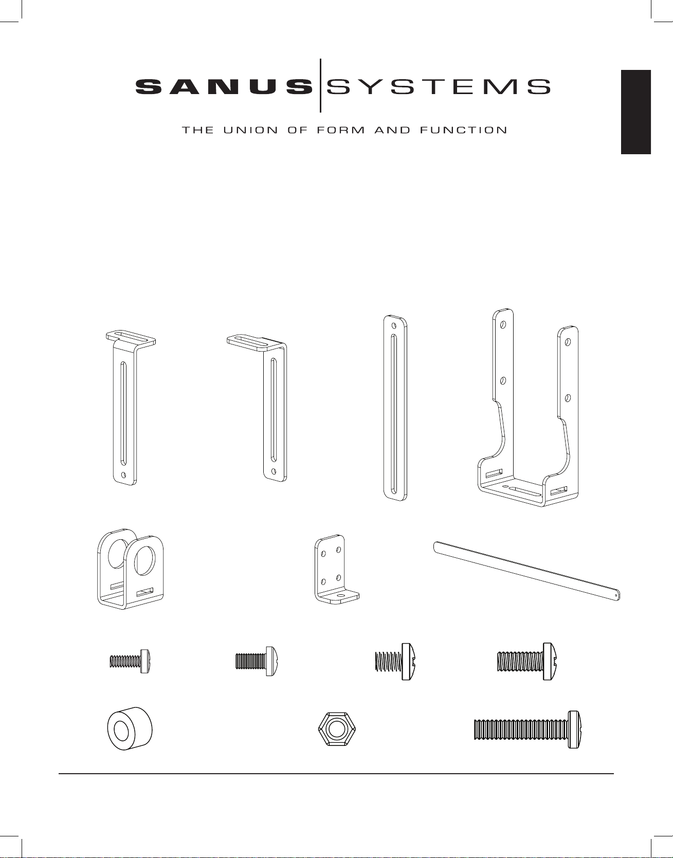
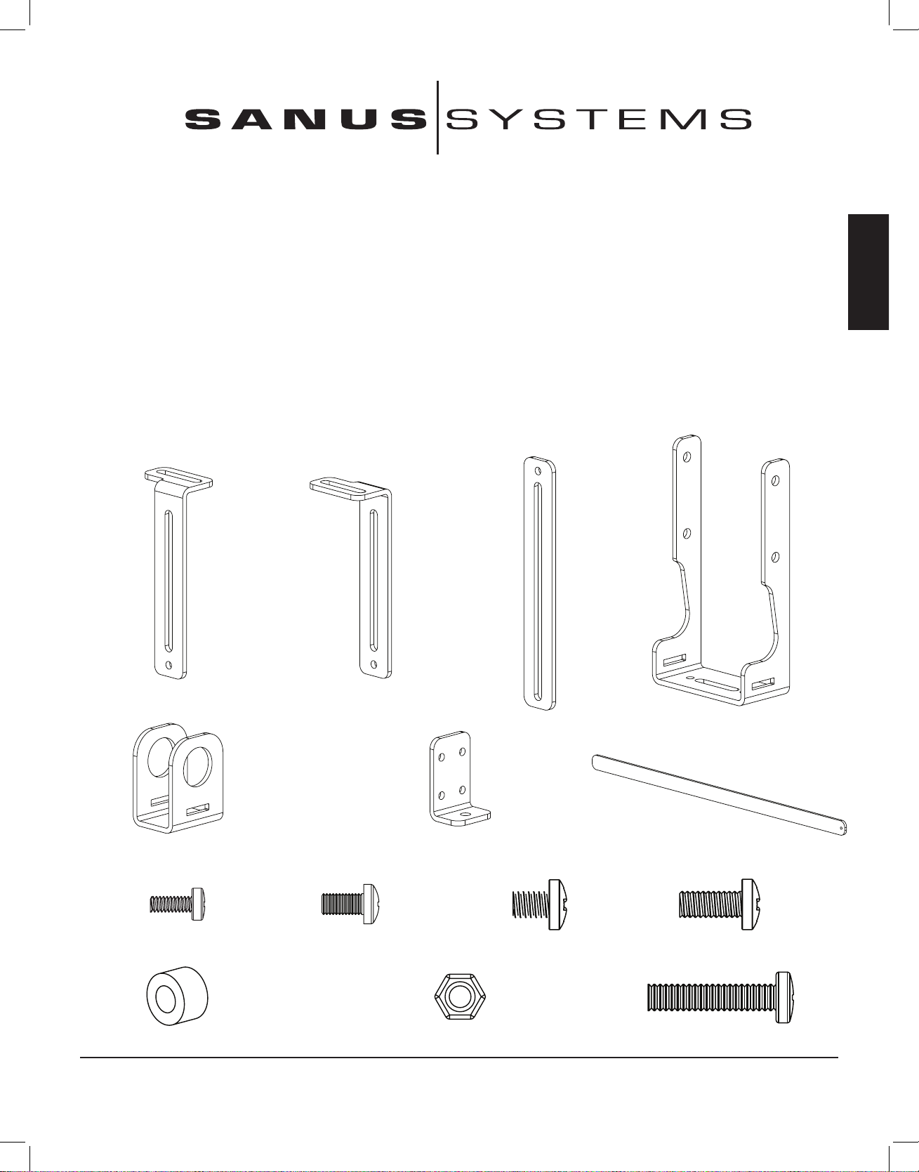
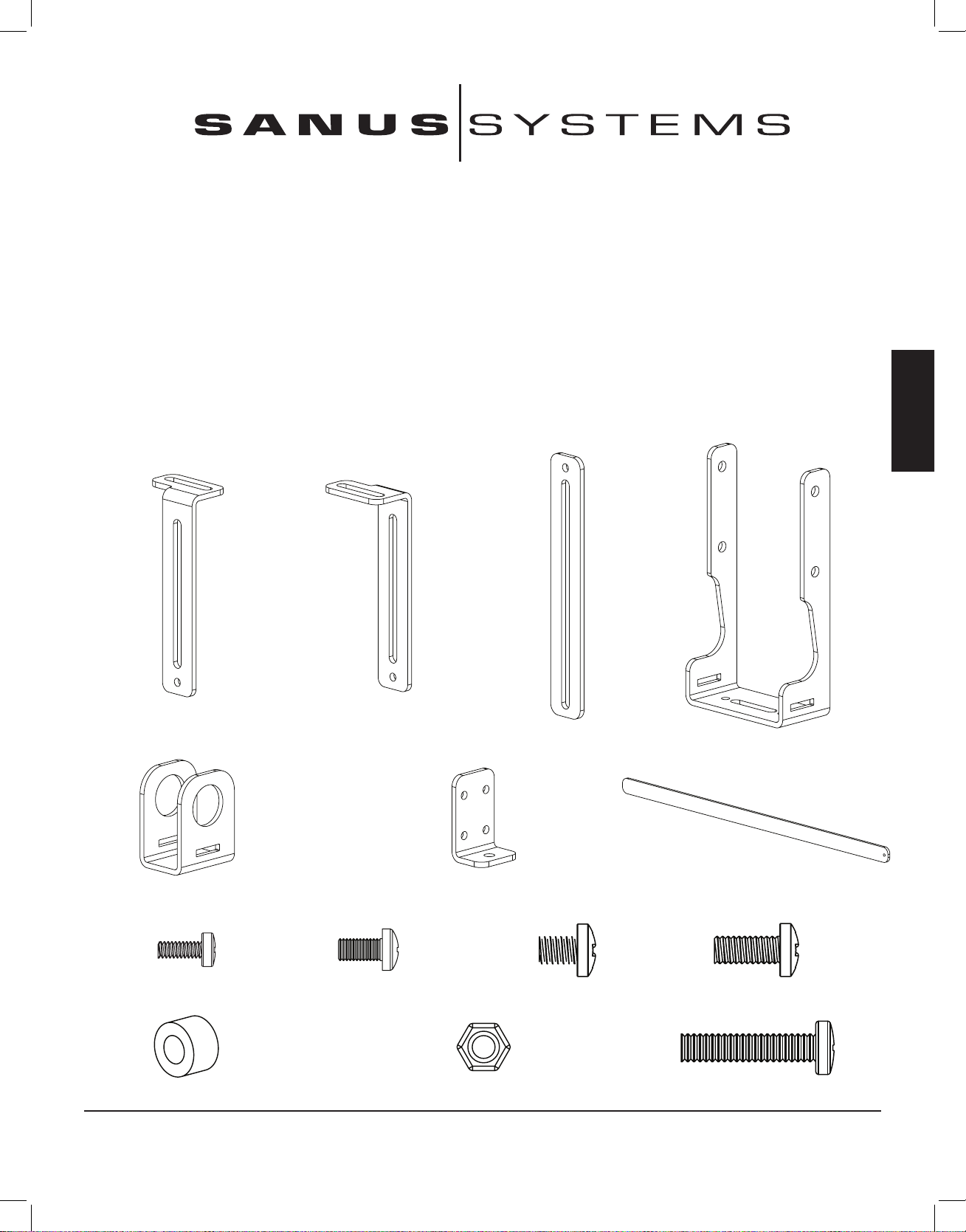
Supplied Parts and Hardware: Hardware shown as actual size.
(1) Left Upper Extension - a (1) Right Upper Extension- b
(2) Lower Extension - c (2) Axis Bracket - d
(2) Bar Bracket - e (2) Speaker Bracket - f (1) Support bar - g
(2) M4 x 10 Bolt - h (2) M5 x 10 Bolt - i (10) 1/4 - 20 x 3/8 Bolt - j (10) 1/4 - 20 x 5/8 Bolt - k
(2) Spacer - l (8) 1/4 - 20 Nut - m (2) 1/4 - 20 x 1500 Bolt - n
Sanus Systems 2221 Hwy 36 West, Saint Paul, MN 55113 11.16.05
Customer Service: 800.359.5520. See complementary Sanus products at www.sanus.com
VMCC1ins_010606_ML.indd 3 1/16/06 10:31:51 AM
Page 4
ENGLISH
For assembly information for the VMSA, VMAA, VMAA18 and VMAA26 see the Steps 1 through 6. For assembly
information for the VMDD and VMDD26 see Steps 7 through 12.
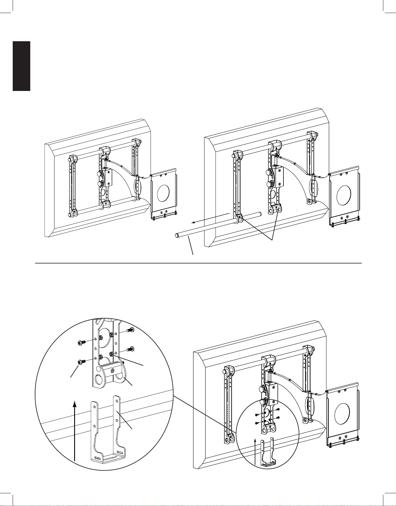
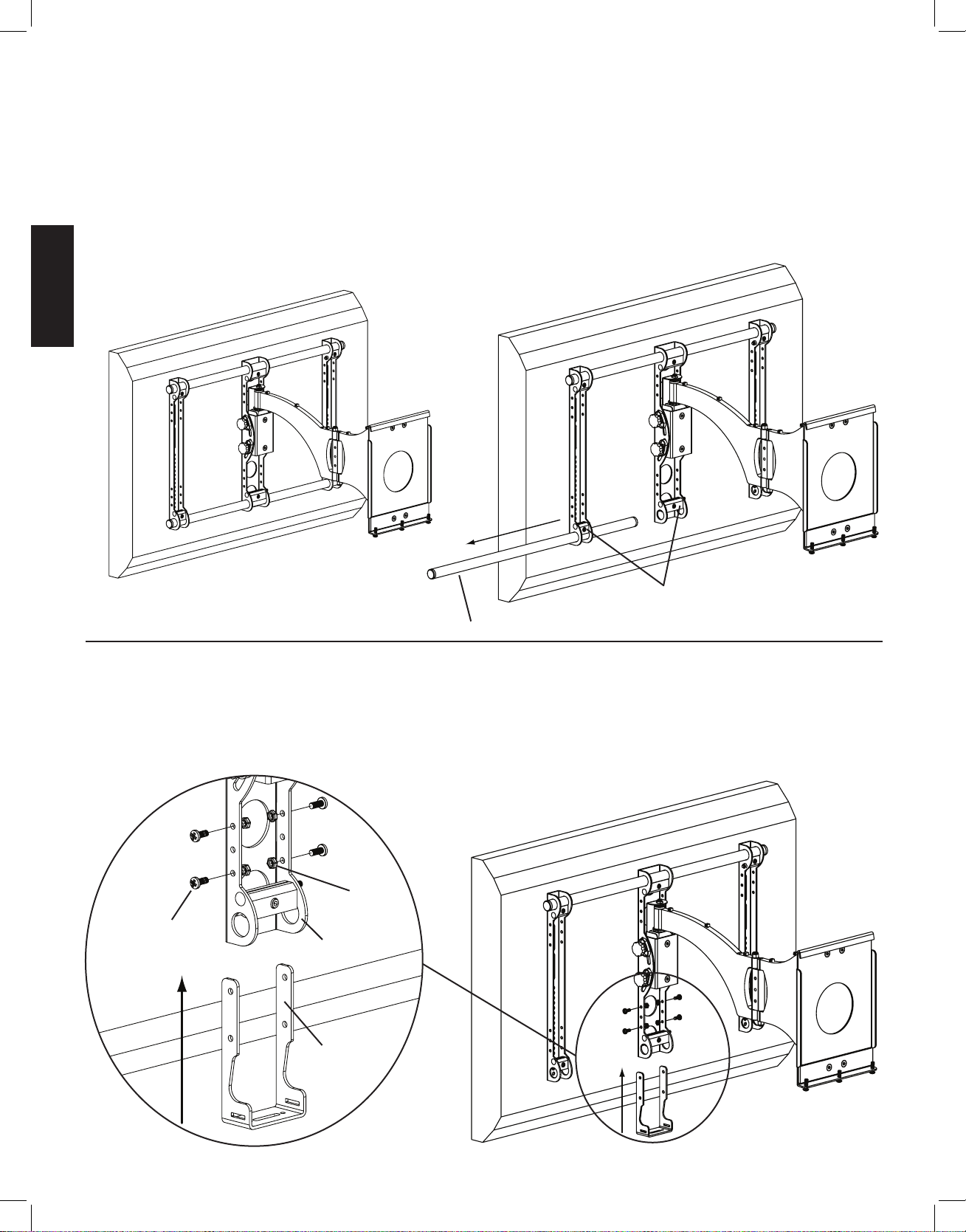
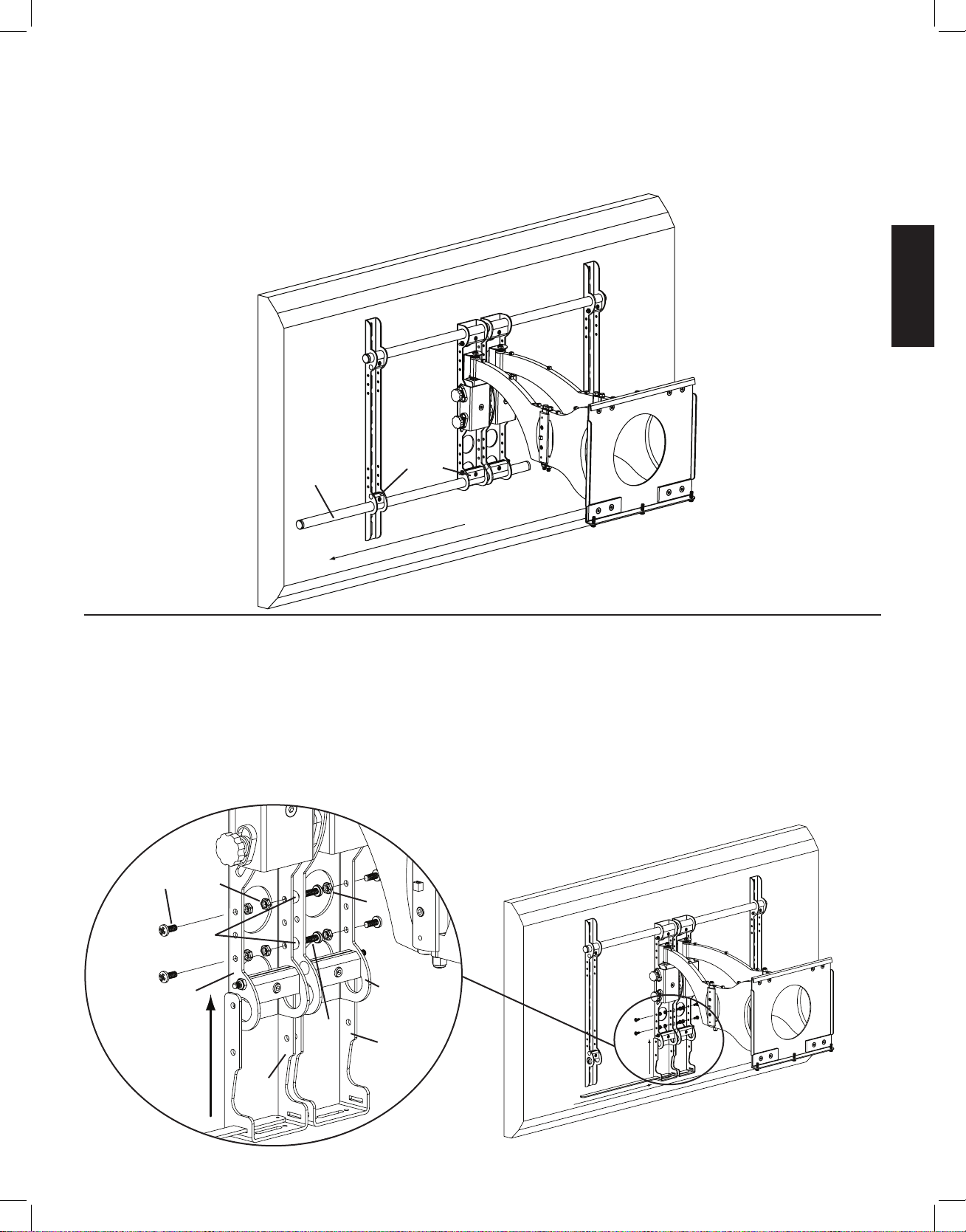
Step 1: Remove mount from Wall Plate and remove lower Cross Tube from the mount assembly.
Remove the mount from the wall plate. Loosen the Allen Bolts in the lower three Vise Assemblies and remove the lower Cross Tube from
the mount assembly. See Diagrams 1a and 1b below.
Diagram 1a Diagram 1b
vise assemblies
cross tube
Step 2: Add Axis Brackets
Position the Axis Bracket (d) so it fits over the Axis Assembly on the mount. Insert a 1/4 - 20 x 5/8 Bolt (k) through the Axis Bracket,
Axis Assembly and into a 1/4 - 20 Nut (m). Repeat process until the Axis Bracket is secured with four 1/4 - 20 x 5/8 Bolts and four 1/4
- 20 Nuts. Tighten each Bolt with a phillips screw driver until secure. See Diagram 2 below.
Detailed View Diagram 2
m
k
axis assembly
d
VMCC1ins_010606_ML.indd 4 1/16/06 10:31:53 AM
Page 5
ENGLISH
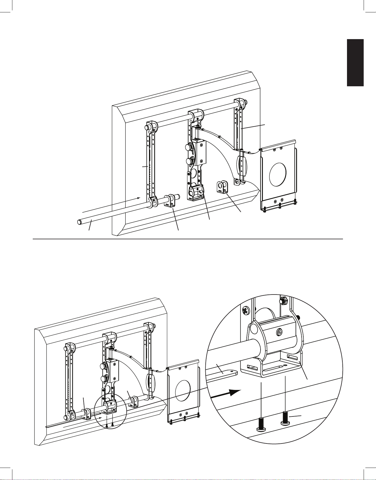
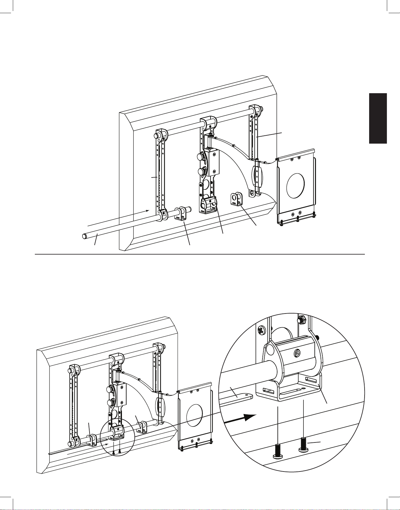
Step 3: Add Bar Brackets
Slide the lower Cross Tube through the Bar Bracket (e), the Axis Assembly, a second Bar Bracket and through the second Monitor Bracket. Tighten all three Vise Assemblies secure the Cross Tube once it is slid through the second Monitor Bracket. See Diagram 3 below.
Diagram 3
monitor bracket
monitor
bracket
e
axis assembly
cross tube e
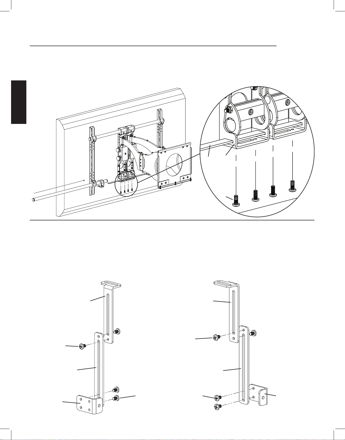
Step 4: Add Support bar
Slide the Support Bar (g) through the Bar Bracket (e), Axis Bracket (d) and through the other Bar Bracket. Make sure the Support Bar
is centered on the wall mount. Thread each 1/4 - 20 x 5/8 Bolt (k) through each hole in the bottom of the Axis Bracket until they bottom
out in the Support bar. See Diagram 4 below.
Diagram 4 Detailed View
g
d
e
e
k
VMCC1ins_010606_ML.indd 5 1/16/06 10:31:55 AM
Page 6
ENGLISH
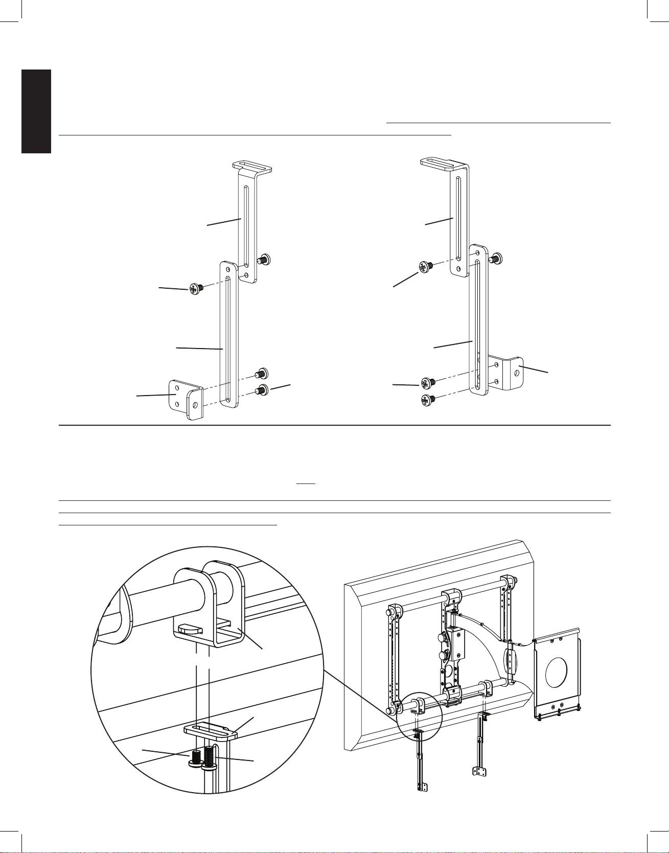
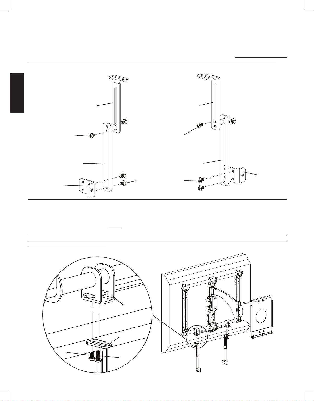
Step 5: Congure Speaker Attachments
Configure the Speaker Attachments as shown in the Diagrams below. Tighten all Bolts with a Phillips screw driver. Repeat process for
the second Speaker Attachment. The Extension assemblies can be adjusted vertically to adjust the vertical position of the speaker. The
depth of the speaker can be adjusted by using the front set of holes or the back set of holes in the Speaker Bracket (f). The Upper Extensions can be adjusted using the slot in the top to adjust the depth of the speaker. Note: In rare occasions, the Lower Extensions may not
be used. In this case, Speaker Bracket (f) may be attached directly to the Upper Extensions (a,b)
Conguration 1 Conguration 2
a b
j j
c c
f
j j
f
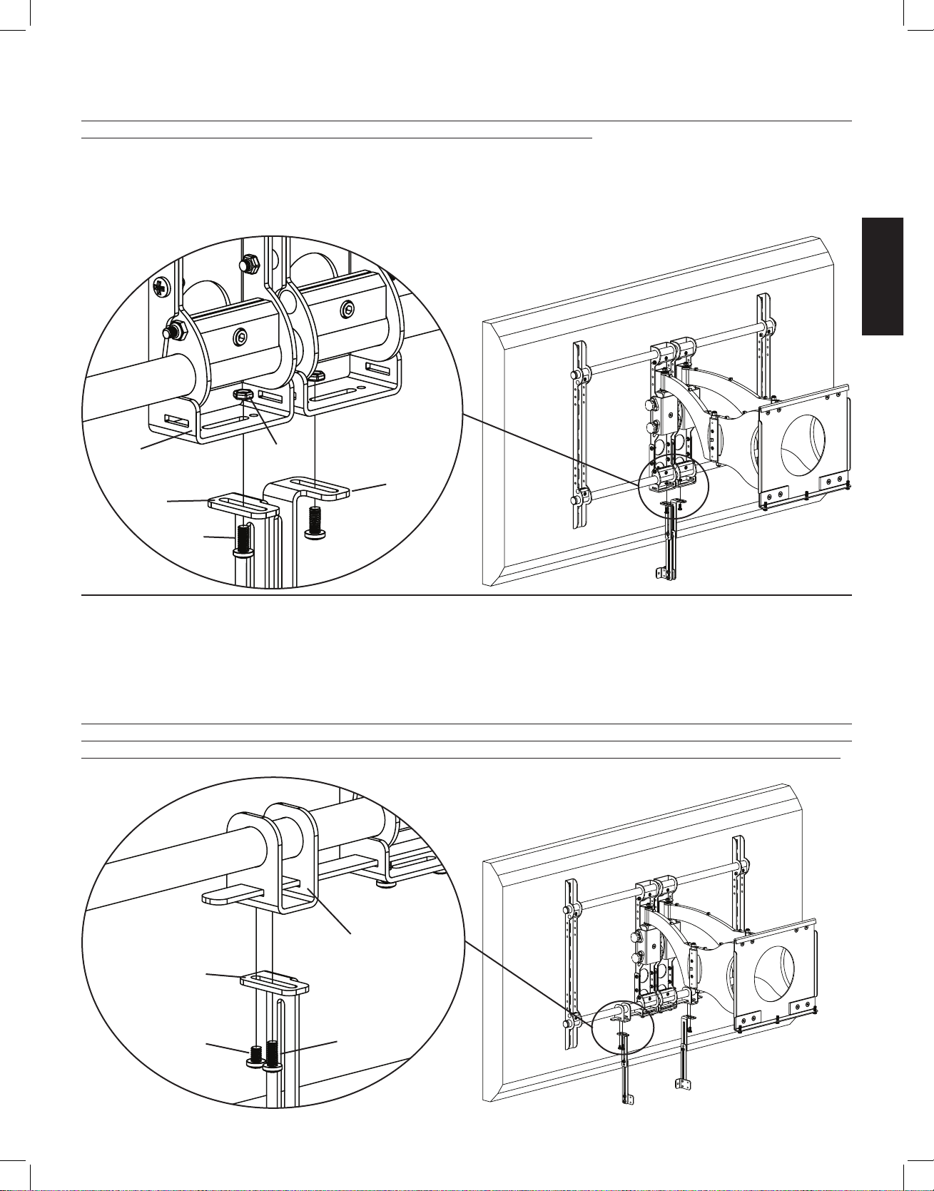
Step 6: Add Speaker Attachments to assembly
Thread a 1/4 - 20 x 3/8 Bolt (j) up through each Upper Extension (a,b) and into the Bar Bracket (e). Tighten to secure the Upper Extension. Thread a 1/4 - 20 x 5/8 Bolt (k) up through each of the Upper Extensions. Do not tighten the 1/4 - 20 x 5/8 Bolts at this time, you
will tighten these so they bottom out into the Support Bar after the speaker is attached.
Note: For Speakers that have threaded inserts that are spaced between 1.75 inches and 15.5 inches use configuration 1. If the threaded
inserts on the speaker are spaced wider than 15.5 inches, the tabs on the Speaker Brackets should face away from each other. In Diagram
6, Speaker Brackets shown facing toward each other.
Detailed View Diagram 6
e
a,b
j
k
VMCC1ins_010606_ML.indd 6 1/16/06 10:31:57 AM
Page 7
ENGLISH
Assembly Instructions for the VMDD and VMDD26 at panel wall mounts.
Step 7: Remove mount from Wall Plate and remove lower Cross Tube from the mount assembly.
Remove the mount from the wall plate. Loosen the Allen Bolts in the lower four Vise Assemblies and remove the lower Cross Tube from
the mount assembly. See Diagram 7 below.
Diagram 7
vise
assemblies
cross tube
Step 8: Add Axis Brackets
If the threaded inserts on your speaker are spaced between 1.5 inches and 5.7 inches, you do NOT need to use the
Support Bar (g) for the installation.
Position the Axis Bracket (d) so it fits the Axis Assembly on the mount. Insert 1/4 - 20 x 5/8 Bolt (k) through the outer side of the Axis
Bracket, Axis Assembly, and into a 1/4 - 20 Nut (m). Insert a 1/4 - 20 x 1.5 Bolt (n) through the inner side of the Axis Bracket, a Spacer
(l), the inner edge of the adjacent Axis Bracket. Thread it into a 1/4 20 Nut. Slide the Support Bar through the slots in each Axis Bracket
until centered with the wall mount. See Diagram 8 below.
Detailed View
Diagram 8
k m
m
l
axis assembly axis assembly
n
d
d
VMCC1ins_010606_ML.indd 7 1/16/06 10:31:59 AM
Page 8

ENGLISH
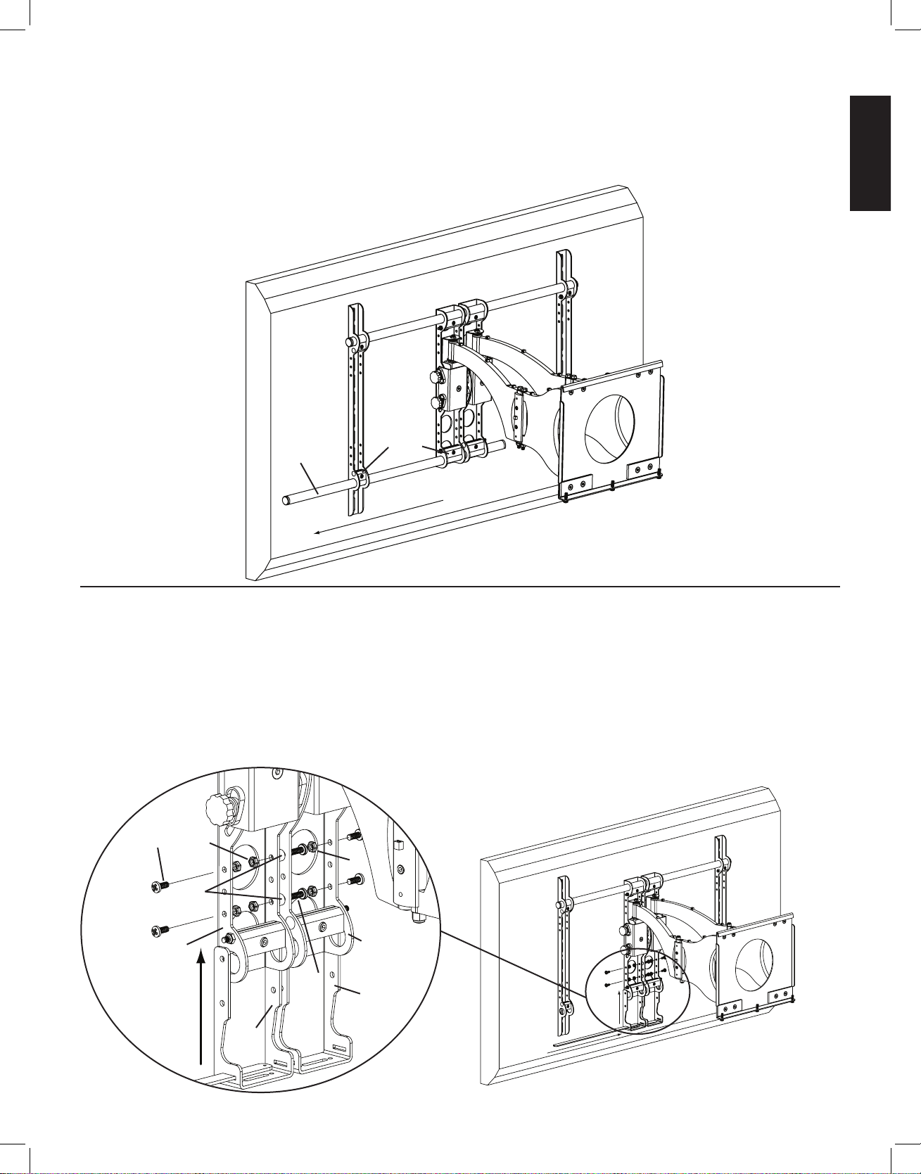
Step 9: Add Bar Brackets
Note: If the Support Bar was not installed in Step 8, only re-install the cross tube in this step.
Slide the lower Cross Tube through the first Monitor Bracket, first Bar Bracket (e), both Axis Assemblies, a second Bar Bracket and
through the second Monitor Bracket. Tighten all four Vise Assemblies to secure the Cross Tube once it is slid through the second Monitor Bracket. Thread each 1/4 - 20 x 5/8 Bolt (k) through each hole in the bottom of the Axis Bracket (d) until they bottom out against the
Support Bar (g). See Diagram 9 below.
Diagram 9 Detailed View
g d
k
Step 10: Congure Speaker Attachments - Support Bar Not installed. If using Support Bar, see Step 5 for conguration.
Configure the Speaker Attachments as seen below. Tighten all Bolts with a Phillips screw driver. Repeat process for the second Speaker
Attachment. See Diagrams below. The Extensions (a,b,c) can be adjusted vertically to adjust the vertical position of the speaker. The
depth of the speaker can be adjusted by using the front set of holes or the back set of holes in the Speaker Bracket (f). The Upper Extensions can be adjusted using the slot in the top to adjust the depth of the speaker. Note: In rare occasions, the Lower Extensions may not
be used.
Conguration 3 Conguration 4
a b
j
j
c c
j j f
f
VMCC1ins_010606_ML.indd 8 1/16/06 10:32:02 AM
Page 9
ENGLISH
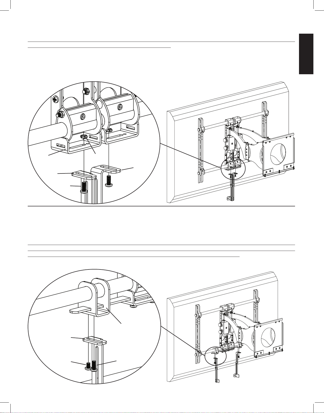
Step 11: Add Speaker Attachments to assembly - Support Bar not installed
Thread a 1/4 - 20 x 3/8 Bolt (j) up through each Upper Extension (a,b) and through the slot in the Axis Bracket (d) and into a 1/4 - 20
Nut (m). Tighten so Upper Extension is secured. See Diagram 11 below.
Note: For Speakers that have threaded inserts that are spaced between 3.75 and 5.7 inches apart the tabs of the Speaker Brackets should
face away from each other. If the threaded inserts on the speaker are spaced between 1.5 and 3.75 inches, the tabs on the Speaker Brackets should face each other. In example shown below, Speaker Brackets are configured for 3.75 to 5.7 inch threaded insert spacing.
Detailed View Diagram 11
d m
a
b
j
Step 12: Add Speaker Attachments to assembly - Support Bar installed
Thread a 1/4 - 20 x 3/8 Bolt (j) up through each Upper Extension (a,b) and into the Bar Bracket (e). Tighten so the Upper Extension is secured to the Bar Bracket. Thread a 1/4 - 20 x 5/8 Bolt (k) up through each of the Upper Extensions. Do not tighten the 1/4 - 20 x 5/8 Bolts
at this time, you will tighten these so they bottom out against the Support Bar after the speaker is attached. See Diagram 12 below.
Note: For Speakers that have threaded inserts that are spaced between 5.7 and 15.5 inches wide, the tabs of the Speaker Brackets should
face each other. If the threaded inserts on the speaker are spaced wider than 15.5 inches, the tabs on the Speaker Brackets should face
away from each other. In Example shown below, Speaker Brackets are configured for the 5.7 to 15.5 range.
Detailed View Diagram 12
e
a,b
j k
VMCC1ins_010606_ML.indd 9 1/16/06 10:32:06 AM
Page 10
ENGLISH
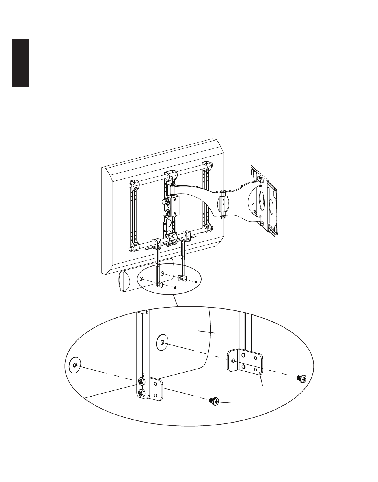
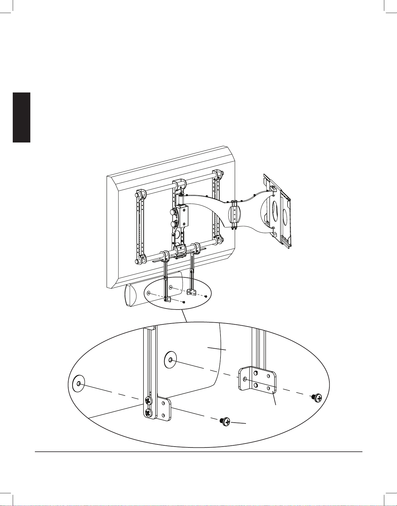
Step 13: Add center channel to VMCC1
Slide the Bar Brackets (e) until the Speaker Brackets (f) line up with the threaded inserts on the back of the speaker. Select the proper
bolt for your center channel speaker by hand threading the M4 x 10 Bolt (h), M5 x 10 Bolt (i) or 1/4 - 20 x 3/8 Bolt (j) into the into the
threaded inserts in the back of the speaker to determine which fits. Once you have selected the proper bolt, insert it through each of the
Speaker Brackets and thread it into the center channel. Tighten each Bolt with a Phillips screw driver. See Diagram 13 below.
You can now center the speaker with the TV by sliding it left or right. Once it is positioned, tighten the 1/4 - 20 x 5/8 Bolt (k), installed
in Step 6, until it bottoms out against the Support Bar.
To adjust the vertical placement of the speaker, loosen the 1/4 - 20 x 3/8 Bolts connecting the Upper and Lower Extension arms and
reposition the arms until center channel is at desired position.
See Step 5 for depth adjustment of speaker.
Diagram 13
speaker
f
j
Sanus Systems 2221 Hwy 36 West, Saint Paul, MN 55113 11.16.05
Customer Service: 800.359.5520. See complementary Sanus products at www.sanus.com
VMCC1ins_010606_ML.indd 10 1/16/06 10:32:08 AM
Page 11
ESPAÑOL
Instrucciones de ensamblaje del modelo: VMCC1
Gracias por elegir el producto VMCC1 de Sanus Systems. El modelo VMCC1 está diseñado para instalar altavoces centrales debajo de
un montaje para instalación mural de pantallas planas Sanus VMSA, VMAA, VMAA18, VMAA26, VMDD o VMDD26.
Advertencia de seguridad: Si no entiende estas instrucciones o si tiene alguna duda con respecto a la seguridad de la instalación, llame a
un contratista calificado o llámenos al 800.359.5520 (en EE.UU.) o al 31 (0) 20 5708938 (en Europa). También nos puede visitar en nuestro
sitio www.sanus.com. Revise los productos cuidadosamente para asegurarse de que no falte ninguna pieza ni esté defectuosa. Nuestros
representantes del servicio de atención al cliente podrán ayudarle rápidamente respondiendo a sus preguntas sobre la instalación o con
respecto a piezas que falten o estén defectuosas. Las piezas de repuesto para los productos comprados a través de un distribuidor autorizado
se enviarán directamente a usted. Nunca use piezas defectuosas. La instalación incorrecta puede provocar daños o lesiones graves. No utilice
este producto para otro fin que no sea el explícitamente especificado por Sanus Systems. Sanus Systems no será responsable por daños ni
lesiones debidos al montaje, ensamblaje o uso incorrectos. Llame a Sanus Systems antes de devolver los productos al punto de compra.
Herramientas necesarias: Destornillador Phillips y llave ajustable.
Piezas y tornillería suministrada: La tornillería se muestra a tamaño real.
(1) Extensión superior izquierda- a (1) Extensión superior derecha- b
(2) Extensión inferior - c (2) Soporte del eje - d
(2) Soporte de la barra - e (2) Soporte del altavoz - f (1) Barra soporte - g
(2) Perno M4 x 10 - h (2) Perno M5 x 10 - i (10) Perno 1/4 - 20 x 3/8 - j (10) Perno 1/4 - 20 x 5/8 - k
(2) Espaciador - l (8) Tuerca 1/4 - 20 - m (2) Perno 1/4 - 20 x 1.5 - n
Sanus Systems 2221 Hwy 36 West, Saint Paul, MN 55113 USA 16-11-05
Servicio de atención al cliente: (800) 359-5520. Vea los productos complementarios de Sanus en el sitio www.sanus.com
VMCC1ins_010606_ML.indd 11 1/16/06 10:32:08 AM
Page 12
ESPAÑOL
Para obtener información sobre el ensamblaje para los modelos VMSA, VMAA, VMAA18 y VMAA26, vea los pasos
1 a 6. Para obtener información sobre el ensamblaje para los modelos VMDD y VMDD26, vea los pasos 7 a 12.
Paso 1: Separación del montaje de la placa para pared y del tubo transversal inferior del conjunto de montaje
Retire el montaje de la placa para pared. Afloje los pernos allen situados en las tres placas de sujeción inferiores y retire el tubo transversal
inferior del conjunto de montaje. Vea los diagramas 1a y 1b más abajo.
Diagrama 1a Diagrama 1b
placas de sujeción
tubo transversal
Paso 2: Adición de los soportes del eje
Coloque el soporte del eje (d) de modo que encaje en el montaje sobre el conjunto del eje. Inserte un perno 1/4 - 20 x 5/8 (k) a través del
soporte del eje, el conjunto del eje y en una tuerca 1/4 - 20 (m). Repita el proceso hasta que el soporte del eje esté sujeto con cuatro pernos
1/4 - 20 x 5/8 y cuatro tuercas 1/4 - 20. Apriete cada perno con un destornillador Phillips hasta asegurarlos. Vea el diagrama 2 más abajo.
Vista detallada Diagrama 2
m
k
conjunto del eje
d
VMCC1ins_010606_ML.indd 12 1/16/06 10:32:09 AM
Page 13
ESPAÑOL
Paso 3: Adición de los soportes de la barra
Deslice el tubo transversal inferior a través del soporte de la barra (e), el conjunto del eje, un segundo soporte de la barra y a través del
segundo soporte del monitor. Apriete las tres placas de sujeción y asegure el tubo transversal una vez que haya pasado por el segundo
soporte del monitor. Vea el diagrama 3 más abajo.
Diagrama 3
soporte del monitor
soporte
del monitor
e
conjunto del eje
tubo transversal e
Paso 4: Adición de la barra soporte
Deslice la barra soporte (g) a través del soporte de la barra (e), el soporte del eje (d) y a través del otro soporte de la barra. Asegúrese de
que la barra soporte esté centrada en el montaje para instalación mural. Enrosque un perno 1/4 - 20 x 5/8 (k) a través de cada agujero de
la parte inferior del soporte del eje hasta que toque fondo en la barra soporte. Vea el diagrama 4 más abajo.
Diagrama 4 Vista detallada
g
d
e
e
k
VMCC1ins_010606_ML.indd 13 1/16/06 10:32:09 AM
Page 14
ESPAÑOL
Paso 5: Conguración de los dispositivos de sujeción de los altavoces
Configure los dispositivos de sujeción de los altavoces como se muestra en el siguiente diagrama. Apriete todos los pernos con un destornillador
Phillips. Repita el proceso con el segundo dispositivo de sujeción del altavoz. Los conjuntos de extensión pueden ajustarse verticalmente para cambiar
la posición vertical del altavoz. La profundidad del altavoz puede ajustarse usando los agujeros delanteros o traseros del soporte del altavoz (f). Las
extensiones superiores pueden ajustarse usando la ranura de la parte superior para cambiar la profundidad del altavoz. Nota: En contadas ocasiones,
las extensiones inferiores no pueden usarse. En tal caso, el soporte del altavoz (f) puede fijarse directamente en las extensiones superiores (a,b).
Conguración 1 Conguración 2
a b
j j
c c
f
j j
f
Paso 6: Adición de los dispositivos de sujeción de los altavoces al conjunto
Enrosque un perno 1/4 - 20 x 3/8 (j) a través de cada una de las extensiones superiores (a,b) y en el soporte de la barra (e). Apriételos para
asegurar la extensión superior. Enrosque un perno 1/4 - 20 x 5/8 (k) a través de cada una de las extensiones superiores. No apriete todavía los
pernos 1/4 - 20 x 5/8 por completo; lo hará después de acoplar el altavoz, de tal modo que alcancen el nivel más bajo en la barra soporte.
Nota: Use la configuración 1 para altavoces con insertos roscados espaciados entre 4,4 cm y 39,4 cm. Si los insertos roscados están
espaciados más de 39,4 cm, las pestañas de los soportes del altavoz deben mirar hacia lados opuestos. En el diagrama 6 se ven los
soportes del altavoz enfrentados entre sí.
Vista detallada Diagrama 6
e
a,b
j
k
VMCC1ins_010606_ML.indd 14 1/16/06 10:32:10 AM
Page 15
ESPAÑOL
Instrucciones de ensamblaje para los montajes para instalación mural de pantallas planas VMDD y VMDD26
Paso 7: Separación del montaje de la placa para pared y del tubo transversal inferior del conjunto de montaje
Retire el montaje de la placa para pared. Afloje los pernos allen situados en las cuatro placas de sujeción inferiores y retire el tubo
transversal inferior del conjunto de montaje. Vea el diagrama 7 más abajo.
Diagrama 7
placas
de sujeción
tubo transversal
Paso 8: Adición de los soportes del eje
Si los insertos roscados de su altavoz están espaciados entre 3,8 cm y 14,5 cm, usted NO necesitará usar la barra
soporte (g) en la instalación.
Coloque el soporte del eje (d) de modo que encaje en el conjunto del eje situado en el montaje. Inserte un perno 1/4 - 20 x 5/8 (k) a través del
lateral externo del soporte del eje, el conjunto del eje y en una tuerca 1/4 - 20 (m). Inserte un perno 1/4 - 20 x 1.5 (n) a través del lateral interno
del soporte del eje, un espaciador (l) y el borde interno del soporte del eje adyacente. Enrósquelo en una tuerca 1/4 - 20. Deslice la barra soporte a
través de las ranuras situadas en cada soporte del eje hasta que esté centrada en el montaje para instalación mural. Vea el diagrama 8 más abajo.
Vista detallada
Diagrama 8
k m
m
l
conjunto del eje conjunto del eje
n
d
d
VMCC1ins_010606_ML.indd 15 1/16/06 10:32:11 AM
Page 16
ESPAÑOL
Paso 9: Adición de los soportes de la barra
Nota: Si la barra soporte no se instaló en el paso 8, en este paso sólo reinstale el tubo transversal.
Deslice el tubo transversal inferior a través del primer soporte del monitor, el primer soporte de la barra (e), ambos conjuntos del eje, un
segundo soporte de la barra y el segundo soporte del monitor. Apriete las cuatro placas de sujeción para asegurar el tubo transversal una
vez que haya pasado por el segundo soporte del monitor. Enrosque un perno 1/4 - 20 x 5/8 (k) en cada uno de los agujeros de la parte
inferior del soporte del eje (d) hasta que toque fondo en la barra soporte (g). Vea el diagrama 9 más abajo.
Diagrama 9 Vista detallada
g d
k
Paso 10: Conguración de los dispositivos de sujeción de los altavoces - Barra soporte no instalada. Si usa la barra
soporte, vea la conguración en el paso 5.
Configure los dispositivos de sujeción de los altavoces como se muestra a continuación. Apriete todos los pernos con un destornillador
Phillips. Repita el proceso con el segundo dispositivo de sujeción del altavoz. Vea los diagramas más abajo. Las extensiones (a,b,c)
pueden ajustarse verticalmente para cambiar la posición vertical del altavoz. La profundidad del altavoz puede ajustarse usando los
agujeros delanteros o traseros del soporte del altavoz (f). Las extensiones superiores pueden ajustarse usando la ranura de la parte
superior para cambiar la profundidad del altavoz. Nota: En contadas ocasiones, las extensiones inferiores no pueden usarse.
Conguración 3 Conguración 4
a b
j
j
c c
j j f
f
VMCC1ins_010606_ML.indd 16 1/16/06 10:32:11 AM
Page 17
ESPAÑOL
Paso 11: Adición de los dispositivos de sujeción de los altavoces al montaje - Barra soporte no instalada
Enrosque un perno 1/4 - 20 x 3/8 (j) a través de cada extensión superior (a,b) y de la ranura del soporte del eje (d), y en una tuerca
1/4 - 20 (m). Apriételo para asegurar la extensión superior. Vea el diagrama 11 más abajo.
Nota: En los altavoces con insertos roscados espaciados entre 9,5 cm y 14,5 cm, las pestañas de los soportes del altavoz deben mirar
hacia lados opuestos. Si los insertos roscados de los altavoces están espaciados entre 3,8 cm y 9,5 cm, las pestañas de los soportes del
altavoz deben estar enfrentadas entre sí. En el ejemplo que se muestra a continuación, los soportes del altavoz están configurados para
que haya un espaciado entre insertos roscados de 9,5 cm a 14,5 cm.
Vista detallada Diagrama 11
d m
a
b
j
Paso 12: Adición de los dispositivos de sujeción de los altavoces al montaje - Barra soporte instalada
Enrosque un perno 1/4 - 20 x 3/8 (j) a través de cada una de las extensiones superiores (a,b) y en el soporte de la barra (e). Apriételo
para asegurar la extensión superior al soporte de la barra. Enrosque un perno 1/4 - 20 x 5/8 (k) a través de cada una de las extensiones
superiores. No apriete todavía los pernos 1/4 - 20 x 5/8 por completo; lo hará después de acoplar el altavoz, de modo que alcancen el
nivel más bajo en la barra soporte. Vea el diagrama 12 más abajo.
Nota: En los altavoces con insertos roscados espaciados entre 14,5 cm y 39,4 cm, las pestañas de los soportes del altavoz deben estar enfrentadas
entre sí. Si los insertos roscados de los altavoces están espaciados más de 39,4 cm, las pestañas de los soportes del altavoz deben estar mirar hacia
lados opuestos. En el ejemplo que se muestra a continuación, los soportes del altavoz están configurados para un rango de 14,5 cm a 39,4 cm.
Vista detallada Diagrama 12
e
a,b
j k
VMCC1ins_010606_ML.indd 17 1/16/06 10:32:13 AM
Page 18
ESPAÑOL
Paso 13: Adición del canal central al VMCC1
Deslice los soportes de la barra (e) hasta alinear los soportes del altavoz (f) con los insertos roscados de la parte trasera del altavoz. Para
seleccionar el perno apropiado para su altavoz central, enrosque manualmente el perno M4 x 10 (h), el M5 x 10 (i) o el 1/4 - 20 x 3/8
(j) en el inserto roscado ubicado en la parte trasera del altavoz para ver cuál encaja. Una vez seleccionado el perno apropiado, insértelo
a través de los soportes del altavoz y enrósquelo en el canal central. Apriete todos los pernos con un destornillador Phillips. Vea el
diagrama 13 más abajo.
Podrá entonces centrar el altavoz con el televisor desplazándolo hacia la izquierda o la derecha. Una vez que esté en posición, apriete el
perno 1/4 - 20 x 5/8 (k), instalado en el paso 6, hasta alcanzar el punto más bajo en la barra soporte.
Para ajustar la posición vertical del altavoz, afloje el perno 1/4 - 20 x 3/8 que conecta los brazos de extensión superior e inferior y
reubique los brazos hasta que el canal central alcance la posición deseada.
Vea el paso 5 para ajustar la profundidad del altavoz.
Diagrama 13
altavoz
f
j
Sanus Systems 2221 Hwy 36 West, Saint Paul, MN 55113 USA 16-11-05
Servicio de atención al cliente: (800) 359-5520. Vea los productos complementarios de Sanus en el sitio www.sanus.com
VMCC1ins_010606_ML.indd 18 1/16/06 10:32:13 AM
Page 19
DEUTSCH
Montageanweisungen für Modell VMCC1
Wir freuen uns, dass Sie sich für Modell VMCC1 von Sanus Systems entschieden haben. Mit Modell VMCC1 wird ein Centerlautsprecher unter
einer Flachbildschirmwandhalterung der Modelle VMSA, VMAA, VMAA18, VMAA26, VMDD oder VMDD26 von Sanus angebracht.
Sicherheitshinweis: Wenn Sie diese Anweisungen nicht verstehen oder Zweifel an der Sicherheit der Montage haben, rufen Sie einen Fachmann
an oder kontaktieren Sie Sanus Systems telefonisch unter +1-800-359-5520 (USA) oder +31-(0)20-570-8938 (Europa). Sie können uns auch im
Internet unter www.sanus.com besuchen. Überprüfen Sie die Zubehörteile sorgfältig, um sicherzugehen, dass keine Teile fehlen oder beschädigt
sind. Unsere Kundendienstmitarbeiter können Ihnen bei Fragen zur Montage und bei fehlenden oder beschädigten Teilen schnell weiterhelfen.
Ersatzteile für bei autorisierten Fachhändlern gekaufte Produkte werden direkt an Ihre Adresse versandt. Verwenden Sie niemals beschädigte Teile!
Unsachgemäße Montage kann Schäden am Gerät und schwere Verletzungen hervorrufen. Verwenden Sie das Produkt nicht für andere als von Sanus
Systems explizit genannte Zwecke. Sanus Systems haftet nicht für Schäden oder Verletzungen, die durch unsachgemäße Montage, fehlerhaften
Zusammenbau oder unsachgemäße Nutzung entstehen. Bitte rufen Sie Sanus Systems an, bevor Sie Produkte beim Händler reklamieren.
Erforderliche Werkzeuge: Kreuzschlitzschraubendreher und Rollgabelschlüssel
Mitgelieferte Teile und Zubehör: Zubehör maßstäblich dargestellt.
(1) Ansatzstück links oben – a 1) Ansatzstück rechts oben – b
(2) Ansatzstück unten – c (2) Achsenhalterung – d
(2) Stangenhalterung – e (2) Lautsprecherhalterung – f (1) Stützschiene – g
(2) Schraube M4 x 10 – h (2) Schraube M5 x 10 – i (10) Schraube 1/4-20 x 3/8 – j (10) Schraube 1/4-20 x 5/8 – k
(2) Distanzstück - l (8) Mutter 1/4-20 – m (2) Schraube 1/4-20 x 1500 – n
D I E E I N H E I T V O N F O R M U N D F U N K T I O N
Sanus Systems 2221 Hwy 36 West, Saint Paul, MN 55113, USA 16.11.05
Kundendienst: 800.359.5520. Siehe ergänzende Sanus-Produkte unter www.sanus.com.
VMCC1ins_010606_ML.indd 19 1/16/06 10:32:14 AM
Page 20

DEUTSCH
Für die Montage an den Modellen VMSA, VMAA, VMAA18 und VMAA26 siehe Schritt 1 bis 6. Für die Montage an
Modell VMDD und VMDD26 siehe Schritt 7 bis 12.
Schritt 1: Halterung von der Wandplatte abnehmen und untere Querstange aus der Halterung herausziehen.
Halterung von der Wandplatte abnehmen. Die Inbusschrauben in den drei unteren Spannvorrichtungen lockern und die untere Querstange
aus der Halterung herausziehen. Siehe Abbildung 1a und 1b.
Abbildung 1a Abbildung 1b
Spannvorrichtungen
Querstange
Schritt 2: Anbringen der Achsenhalterungen
Achsenhalterung (d) so positionieren, dass sie auf die Achseneinheit der Halterung geschoben werden kann. Eine Schraube 1/4-20 x 5/8 (k) durch
die Achsenhalterung, die Achseneinheit und in die Mutter 1/4-20 (m) eindrehen. Vorgang wiederholen, bis die Achsenhalterung mit vier Schrauben
1/4-20 x 5/8 und vier Muttern 1/4-20 sicher befestigt ist. Alle Schrauben mit einem Kreuzschlitzschraubendreher festziehen. Siehe Abbildung 2.
Detailansicht Abbildung 2
m
k
Achseneinheit
d
VMCC1ins_010606_ML.indd 20 1/16/06 10:32:14 AM
Page 21

DEUTSCH
Schritt 3: Anbringen der Stangenhalterungen
Die untere Querstange durch die Stangenhalterung (e), die Achseneinheit, eine weitere Stangenhalterung und die zweite Monitorhalterung
schieben. Die Querstange durch die zweite Monitorhalterung schieben und alle drei Spannvorrichtungen fest an die Querstange
anschrauben. Siehe Abbildung 3.
Abbildung 3
Monitorhalterung
Monitor-
halterung
e
Achseneinheit
Querstange e
Schritt 4: Anbringen der Stützschiene
Die Stützschiene (g) durch die Stangenhalterung (e), die Achsenhalterung (d) und durch die andere Stangenhalterung schieben. Die
Stützschiene muss mit der Wandhalterung mittig ausgerichtet sein. Alle Schrauben 1/4-20 x 5/8 (k) durch die Bohrungen an der Unterseite
der Achsenhalterung eindrehen, bis sie an die Stützschiene stoßen. Siehe Abbildung 4.
Abbildung 4 Detailansicht
g
d
e
e
k
VMCC1ins_010606_ML.indd 21 1/16/06 10:32:15 AM
Page 22

DEUTSCH
Schritt 5: Konguration der Lautsprecherhalterungen
Die Lautsprecherhalterungen werden wie in der Abbildung unten dargestellt konfiguriert. Alle Schrauben mit einem Kreuzschlitzschraubendreher festziehen. Den Vorgang für die zweite Lautsprecherhalterung wiederholen. Die zusammengefügten Ansatzstücke können vertikal
verstellt werden, um die vertikale Position der Lautsprecher einzustellen. Die Lautsprechertiefe wird mit den vorderen bzw. hinteren
Bohrungen in der Lautsprecherhalterung (f) eingestellt. Das obere Ansatzstück kann an dem oberen Schlitz verstellt werden, um die
Lautsprechertiefe einzustellen. Hinweis: Es kann vorkommen, dass das untere Ansatzstück nicht verwendet werden muss. In diesem Fall
wird die Lautsprecherhalterung (f) direkt an den oberen Ansatzstücken (a, b) angebracht.
Konguration 1 Konguration 2
a b
j j
c c
f
j j
f
Schritt 6: Anbringen der Lautsprecherhalterungen an der Einheit
Je eine Schraube 1/4-20 x 3/8 (j) nach oben durch alle oberen Ansatzstücke (a, b) und in die Stangenhalterung (e) eindrehen. Festziehen, um das
obere Ansatzstück zu befestigen. Je eine Schraube 1/4-20 x 5/8 (k) nach oben durch alle oberen Ansatzstücke eindrehen. Die Schrauben 1/4-20 x 5/8
zu diesem Zeitpunkt noch nicht festziehen. Sie werden nach dem Anbringen der Lautsprecher bis an die Stützschiene gedreht und festgezogen.
Hinweis: Für Lautsprecher mit Gewindeeinsätzen im Abstand von 4,4 cm bis 39,4 cm Konfiguration 1 verwenden. Beträgt der Abstand
der Gewindeeinsätze an den Lautsprechern über 39,4 cm, müssen die Winkel der Lautsprecherhalterungen voneinander wegweisen. In
Abbildung 6 weisen die Lautsprecherhalterungen aufeinander zu.
Detailansicht Abbildung 6
e
a,b
j
k
VMCC1ins_010606_ML.indd 22 1/16/06 10:32:15 AM
Page 23

DEUTSCH
Montageanweisungen für die Flachbildschirmwandhalterungen Modell VMDD und VMDD26
Schritt 7: Halterung von der Wandplatte abnehmen und untere Querstange aus der Halterung herausziehen.
Halterung von der Wandplatte abnehmen. Die Inbusschrauben in den vier unteren Spannvorrichtungen lockern und die untere Querstange
aus der Halterung herausziehen. Siehe Abbildung 7.
Abbildung 7
Spann-
vorrichtungen
Querstange
Schritt 8: Anbringen der Achsenhalterungen
Beträgt der Abstand der Gewindeeinsätze an dem Lautsprecher zwischen 3,8 cm und 14,5 cm, wird die Stützschiene
zur Befestigung NICHT benötigt.
Achsenhalterung (d) so positionieren, dass sie auf die Achseneinheit der Halterung geschoben werden kann. Eine Schraube 1/4-20 x 5/8
(k) durch die Außenseite der Achsenhalterung, die Achseneinheit und in die Mutter 1/4-20 (m) eindrehen. Eine Schraube 1/4-20 x 1,5 (n)
durch die Innenseite der Achsenhalterung, ein Distanzstück (l) und die Innenseite der daneben befindlichen Achsenhalterung eindrehen.
Die Schraube in eine Mutter 1/4-20 eindrehen. Die Stützschiene durch die Schlitze in den Achsenhalterungen schieben, bis sie mit der
Wandhalterung mittig ausgerichtet sind. Siehe Abbildung 8.
Detailansicht
Abbildung 8
k m
m
l
Achseneinheit Achseneinheit
n
d
d
VMCC1ins_010606_ML.indd 23 1/16/06 10:32:16 AM
Page 24

DEUTSCH
Schritt 9: Anbringen der Stangenhalterungen
Hinweis: Wenn die Stützschiene in Schritt 8 nicht angebaut wurde, in diesem Schritt nur die Querstange wieder anbauen.
Die untere Querstange durch die erste Monitorhalterung, die erste Stangenhalterung (e), beide Achseneinheiten, die zweite
Stangenhalterung und die zweite Monitorhalterung schieben. Die Querstange durch die zweite Monitorhalterung schieben und alle vier
Spannvorrichtungen fest an die Querstange anschrauben. Alle Schrauben 1/4-20 x 5/8 (k) durch die Bohrungen an der Unterseite der
Achsenhalterung (d) eindrehen, bis sie an die Stützschiene (g) stoßen. Siehe Abbildung 9.
Abbildung 9 Detailansicht
g d
k
Schritt 10: Konguration der Lautsprecherhalterungen – Stützschiene nicht angebaut. Wird die Stützschiene verwendet,
siehe Schritt 5 zur Konguration.
Lautsprecherhalterungen wie unten dargestellt konfigurieren. Alle Schrauben mit einem Kreuzschlitzschraubendreher festziehen. Den
Vorgang für die zweite Lautsprecherhalterung wiederholen. Siehe folgende Abbildungen. Die Ansatzstücke (a, b, c) können vertikal
verstellt werden, um die vertikale Position der Lautsprecher einzustellen. Die Lautsprechertiefe wird mit den vorderen bzw. hinteren
Bohrungen in der Lautsprecherhalterung (f) eingestellt. Das obere Ansatzstück kann an dem oberen Schlitz verstellt werden, um die
Lautsprechertiefe einzustellen. Hinweis: Es kann vorkommen, dass das untere Ansatzstück nicht verwendet werden muss.
Konguration 3 Konguration 4
a b
j
j
c c
j j f
f
VMCC1ins_010606_ML.indd 24 1/16/06 10:32:17 AM
Page 25

DEUTSCH
Schritt 11: Anbringen der Lautsprecherhalterungen an der Einheit – Stützschiene nicht angebaut
Je eine Schraube 1/4-20 x 3/8 (j) nach oben durch alle oberen Ansatzstücke (a, b) und durch den Schlitz in der Achsenhalterung (d) in
eine Mutter 1/4-20 (m) eindrehen. Festziehen, um das obere Ansatzstück zu befestigen. Siehe Abbildung 11.
Hinweis: Für Lautsprecher mit Gewindeeinsätzen im Abstand von 9,5 cm bis 14,5 cm müssen die Winkel der Lautsprecherhalterungen
voneinander wegweisen. Wenn die Gewindeeinsätze an den Lautsprechern einen Abstand zwischen 3,8 cm und 9,5 cm aufweisen,
müssen die Winkel der Lautsprecherhalterungen aufeinander zu weisen. Im unteren Beispiel wurden die Lautsprecherhalterungen für
einen Abstand von 9,5 cm bis 14,5 cm zwischen den Gewindeeinsätzen konfiguriert.
Detailansicht Abbildung 11
d m
a
b
j
Schritt 12: Anbringen der Lautsprecherhalterungen an der Einheit – Stützschiene angebaut
Je eine Schraube 1/4-20 x 3/8 (j) nach oben durch alle oberen Ansatzstücke (a, b) und in die Stangenhalterung (e) eindrehen. Festziehen,
um das obere Ansatzstück an der Stangenhalterung zu befestigen. Je eine Schraube 1/4-20 x 5/8 (k) nach oben durch alle oberen
Ansatzstücke eindrehen. Die Schrauben 1/4-20 x 5/8 zu diesem Zeitpunkt noch nicht festziehen. Sie werden nach dem Anbringen der
Lautsprecher bis an die Stützschiene gedreht und festgezogen. Siehe Abbildung 12.
Hinweis: Für Lautsprecher mit Gewindeeinsätzen im Abstand von 14,5 cm bis 39,4 cm müssen die Winkel der Lautsprecherhalterungen
aufeinander zu weisen. Wenn die Gewindeeinsätze an den Lautsprechern einen Abstand von über 39,4 cm aufweisen, müssen die Winkel
der Lautsprecherhalterungen voneinander wegweisen. Im unteren Beispiel sind die Lautsprecherhalterungen für einen Bereich zwischen
14,5 cm und 39,4 cm konfiguriert.
Detailansicht Abbildung 12
e
a, b
j k
VMCC1ins_010606_ML.indd 25 1/16/06 10:32:18 AM
Page 26

DEUTSCH
Schritt 13: Anbringen des Centerlautsprechers an Modell VMCC1
Stangenhalterungen (e) so einschieben, dass die Lautsprecherhalterungen (f) mit den Gewindeeinsätzen auf der Rückseite des Lautsprechers
ausgerichtet sind. Die richtige Schraube für den Centerlautsprecher durch probeweises Eindrehen der Schrauben M4 x 10 (h), M5 x 10 (i) und
1/4-20 x 3/8 (j) in die Gewindeeinsätze auf der Rückseite des Lautsprechers auswählen. Die passende Schraube durch die Lautsprecherhalterungen
einführen und in den Centerlautsprecher eindrehen. Alle Schrauben mit einem Kreuzschlitzschraubendreher festziehen. Siehe Abbildung 13.
Der Lautsprecher kann nun mit dem Fernseher mittig ausgerichtet werden, indem er nach links oder rechts geschoben wird. Wenn sich der
Lautsprecher in der richtigen Position befindet, die Schraube 1/4-20 x 5/8 (k) (in Schritt 6 eingebaut) festziehen, bis sie an die Stützschiene stößt.
Zur Einstellung der vertikalen Position des Lautsprechers die Schrauben 1/4-20 x 3/8, durch die das obere und untere Ansatzstück
zusammengehalten werden, lockern und die Arme neu positionieren, bis der Centerlautsprecher sich in der gewünschten Position befindet.
Siehe Schritt 5 für die Tiefeneinstellung des Lautsprechers.
Abbildung 13
Lautsprecher
f
j
Sanus Systems 2221 Hwy 36 West, Saint Paul, MN 55113, USA 16.11.05
Kundendienst: 800.359.5520. Siehe ergänzende Sanus-Produkte unter www.sanus.com.
VMCC1ins_010606_ML.indd 26 1/16/06 10:32:19 AM
Page 27

FRANÇAIS
Instructions d’assemblage pour le modèle : VMCC1
Nous vous remercions d’avoir choisi le VMCC1 de Sanus Systems. Le VMCC1 permet d’installer une enceinte de haut parleur centrale sous
un montant mural Sanus VMSA, VMAA, VMAA18, VMAA26, VMDD ou un montant mural VMDD26 pour téléviseur à écran plat.
Avertissements relatifs à la sécurité : Si vous ne comprenez pas ces instructions ou si vous avez un doute quant à la sécurité de cette installation, veuillez
faire appel à un technicien qualifié ou communiquez avec Sanus en composant le 1-800-359-5520 (aux É.-U.), ou le 31 (0) 20 5708938 (pour l’Europe). Vous pouvez
aussi allez sur notre site Web au www.sanus.com. Vérifiez soigneusement la trousse afin de vous assurer qu’il n’y a aucune pièce manquante ou défectueuse.
Les représentants de notre service à la clientèle peuvent répondre rapidement à toute question concernant l’installation ou les pièces manquantes ou
endommagées. Les pièces de rechange de produits achetés auprès de distributeurs agréés vous seront livrées directement. N’utilisez jamais de pièces
défectueuses. Une installation incorrecte peut entraîner des dommages ou des blessures graves. Ce produit ne doit être utilisé que pour des usages
explicitement spécifiés par Sanus Systems. Sanus Systems ne pourra être tenu responsable de dommages ou de blessures dus à un montage incorrect,
à un assemblage incorrect ou à un usage incorrect. Veuillez contacter Sanus Systems avant de retourner les produits au point de vente.
Outils nécessaires : tournevis cruciforme et clé à molette
Pièces et matériel fournis : Le matériel est illustré grandeur réelle.
(1) Extension supérieure gauche - a (1) Extension supérieure droite- b
(2) Extension inférieure - c (2) Support d’axe - d
(2) Support de barre - e (2) Support du haut-parleur - f (1) Barre de soutien - g
(2) Boulon M4 x 10 - h (2) Boulon M5 x 10 - i (10) Boulon 1/4 - 20 x 3/8 - j (10) Boulon 1/4 - 20 x 5/8 - k
(2) Entretoise - l (8) Écrou 1/4-20 - m (2) Boulon 1/4 - 20 x 1500 - n
L’ U N I O N D E L A F O R M E E T D E L A F O N C T I O N
Sanus Systems 2221 Hwy 36 West, Saint Paul, MN 55113 USA 11.16.05
Service à la clientèle : 800.359.5520. Pour les produits Sanus complémentaires, visitez le site www.sanus.com
VMCC1ins_010606_ML.indd 27 1/16/06 10:32:20 AM
Page 28

FRANÇAIS
Pour obtenir de l’information sur l’assemblage des modèles VMSA, VMAA, VMAA18 et VMAA26, reportez-vous aux étapes
1 à 6. Pour obtenir de l’information sur l’assemblage des modèles VMDD et VMDD26, reportez-vous aux étapes 7 à 12.
Étape 1 : Retrait du montant de la plaque murale et du tube transversal au bas du montant.
Retirez le montant de la plaque murale. Desserrez les vis Allen dans les trois étaux inférieurs et retirez le tube transversal inférieur du
montant. Reportez-vous aux schémas 1a et 1b ci-dessous.
Schéma 1a Schéma 1b
étaux
tube transversal
Étape 2 : Ajout des supports d’axe
Positionnez le support d’axe (d) de sorte qu’il coiffe l’assemblage de l’axe sur le montant. Insérez un boulon 1/4 - 20 x 5/8 (k) qui
traversera le support d’axe et l’assemblage de l’axe pour se loger dans un écrou 1/4 - 20 (m). Répétez la procédure jusqu’à ce que
le support d’axe soit bien fixé au montant par quatre boulons 1/4 - 20 x 5/8 et quatre écrous 1/4 - 20. Serrez chaque boulon avec un
tournevis cruciforme jusqu’à ce que l’assemblage soit solide. Reportez-vous au schéma 2 ci-dessous.
Vue détaillée Schéma 2
m
k
assemblage de l’axe
d
VMCC1ins_010606_ML.indd 28 1/16/06 10:32:20 AM
Page 29

FRANÇAIS
Étape 3 : Ajout des supports de barre
Glissez le tube transversal inférieur à travers le support de barre (e), l’assemblage de l’axe, le second support de barre et le second
support du moniteur. Serrez les trois étaux sur le tube transversal une fois qu’il a glissé à travers le second support du moniteur. Reportezvous au schéma 3 ci-dessous.
Schéma 3
support du moniteur
support
du
moniteur
e
assemblage de l’axe
tube transversal e
Étape 4 : Ajout de la barre de soutien
Glissez la barre de soutien (g) à travers le support de barre (e), le support d’axe (d) et l’autre soutien de barre. Assurez-vous que la barre
de soutien est centrée sur le montant mural. Enfilez un boulon 1/4 - 20 x 5/8 (k) dans chaque trou de la partie inférieure du soutien d’axe
jusqu’à ce qu’il soit fermement appuyé sur la barre de soutien. Reportez-vous au schéma 4 ci-dessous.
Schéma 4 Vue détaillée
g
d
e
e
k
VMCC1ins_010606_ML.indd 29 1/16/06 10:32:20 AM
Page 30

FRANÇAIS
Étape 5 : Conguration des pièces de xation du haut-parleur
Configurez les pièces de fixation du haut-parleur tel qu’il est indiqué dans les schémas ci-dessous. Serrez tous les boulons avec un
tournevis cruciforme. Répétez la procédure pour la deuxième pièce de fixation du haut-parleur. Les extensions sont réglables à la
verticale de manière à s’ajuster à la position verticale du haut-parleur. La profondeur du haut-parleur peut être réglée en utilisant la série
de trous à l’avant ou la série de trous à l’arrière du support du haut-parleur (f). Les extensions supérieures peuvent être réglées en utilisant
la fente sur le dessus pour régler la profondeur du haut-parleur. Remarque : En de rares occasions, on ne peut pas utiliser les extensions
inférieures. En pareil cas, le support du haut-parleur (f) peut être fixé directement aux extensions supérieures (a, b).
Conguration 1 Conguration 2
a b
j j
c c
f
j j
f
Étape 6 : Ajout des pièces de xation du haut-parleur à l’assemblage
Enfilez un boulon 1/4 - 20 x 3/8 (j) à travers chaque extension supérieure (a, b) et dans le support de barre (e). Serrez pour bien fixer
l’extension supérieure. Enfilez un boulon 1/4 - 20 x 5/8 (k) à travers chacune des extensions supérieures. Ne serrez pas les boulons
1/4 - 20 x 5/8 pour l’instant, vous le ferez jusqu’à ce qu’ils s’appuient fermement sur la barre de soutien après avoir fixé le haut-parleur.
Remarque : Pour les haut-parleurs dotés d’inserts filetés espacés de 4,4 cm à 39,4 cm, utilisez la configuration 1. Si les inserts filetés
sur le haut-parleur sont espacés de plus de 39,4 cm, les pattes sur les supports de haut-parleur doivent être orientées dans des directions
opposées. Dans le schéma 6, les supports du haut-parleur sont face à face.
Vue détaillée Schéma 6
e
a, b
j
k
VMCC1ins_010606_ML.indd 30 1/16/06 10:32:21 AM
Page 31

FRANÇAIS
Instructions d’assemblage des montants muraux VMDD et VMDD26 pour téléviseurs à écran plat.
Étape 7 : Retrait du montant de la plaque murale et du tube transversal inférieur du montant.
Retirez le montant de la plaque murale. Desserrez les vis Allen des quatre étaux inférieurs et retirez le tube transversal inférieur du
montant. Reportez-vous au schéma 7 ci-dessous.
Schéma 7
assemblages
tube des étaux
transversal
Étape 8 : Ajout des supports d’axe
Si les inserts letés sur le haut-parleur sont espacés de 3,8 cm à 14,5 cm, vous N’AVEZ PAS BESOIN de la barre
de soutien (g) pour l’installation.
Positionnez le support d’axe (d) de sorte qu’il s’adapte bien à l’assemblage de l’axe sur le montant. Insérez un boulon 1/4 - 20 x 5/8 (k)
qui traversera le côté extérieur du support d’axe et l’assemblage de l’axe pour se loger dans un écrou 1/4 - 20 (m). Insérez un boulon
de 1/4 - 20 x 1,5 (n) en passant par la face intérieure du support de l’axe, et posez une entretoise (l) sur la face interne du support d’axe
adjacent. Enfilez ce boulon dans un écrou 1/4 20. Glissez la barre de soutien à travers les deux fentes dans chaque support d’axe jusqu’à
ce qu’elle soit centrée par rapport au montant mural. Reportez-vous au schéma 8 ci-dessous.
Vue détaillée
Schéma 8
k m
m
l
assemblage assemblage
de l’axe de l’axe
n
d
d
VMCC1ins_010606_ML.indd 31 1/16/06 10:32:22 AM
Page 32

FRANÇAIS
Étape 9 : Ajout des supports de barre
Remarque : Si la barre de soutien n’a pas été installée à l’étape 8, réinstallez seulement le tube transversal au
cours de la présente étape.
Glissez le tube transversal inférieur à travers le premier support de moniteur (e), les deux assemblages de l’axe, le second support de
barre et le second support du moniteur. Serrez les quatre étaux pour fixer le tube transversal une fois qu’il est passé à travers le second
support du moniteur. Enfilez un boulon 1/4 - 20 x 5/8 (k) dans chaque trou dans la partie inférieure du soutien de l’axe (d) jusqu’à ce tous
les boulons soient fermement appuyés sur la barre de soutien. Reportez-vous au schéma 9 ci-dessous.
Schéma 9 Vue détaillée
g d
k
Étape 10 : Congurez les pièces de xation du haut-parleur - sans installer de barre de soutien. Si vous utilisez une barre
de soutien, suivez les instructions de conguration fournies à l’étape 5.
Configurez les pièces de fixation du haut-parleur tel qu’indiqué ci-dessous. Serrez tous les boulons avec un tournevis cruciforme. Répétez la
procédure pour la deuxième pièce de fixation du haut-parleur. Reportez-vous aux schémas ci-dessous. Les extensions (a, b, c) sont réglables à
la verticale de manière à s’ajuster à la position verticale du haut-parleur. La profondeur du haut-parleur peut être réglée en utilisant la série de
trous à l’avant ou la série de trous à l’arrière du support du haut-parleur (f). Les extensions supérieures peuvent être réglées en utilisant la fente
sur le dessus pour régler la profondeur du haut-parleur. Remarque : En de rares occasions, on ne peut pas utiliser les extensions inférieures.
Conguration 3 Conguration 4
a b
j
j
c c
j j f
f
VMCC1ins_010606_ML.indd 32 1/16/06 10:32:22 AM
Page 33

FRANÇAIS
Étape 11 : Ajout des pièces de xation du haut-parleur à l’assemblage - sans installer de barre de soutien
Faites passer un boulon 1/4 - 20 x 3/8 (j) dans chaque extension supérieure (a, b) et à travers la fente dans le support d’axe (d) pour le loger
enfin dans un écrou 1/4 - 20 (m). Serrez le tout afin que l’extension supérieure soit bien fixée. Reportez-vous au schéma 11 ci-dessous.
Remarque : Si les inserts filetés sont espacés de 9,5 cm à 14,5 cm sur les haut-parleurs, les pattes des supports de haut-parleur doivent être orientées en directions opposées. Si les inserts filetés sont espacés de 3,8 cm à 9,5 cm, les pattes des supports de haut-parleur doivent être posées
face à face. Dans l’exemple ci-dessous, les supports de haut-parleur sont configurés pour des inserts filetés espacés de 9,5 cm à 14,5 cm.
Vue détaillée Schéma 11
d m
a
b
j
Étape 12 : Ajout des pièces de xation du haut-parleur à l’assemblage - Avec installation de la barre de soutien
Enfilez un boulon 1/4 - 20 x 3/8 (j) à travers chaque extension supérieure (a, b) et dans le support de barre (e). Serrez de manière à bien
fixer l’extension supérieure au support de barre. Enfilez un boulon 1/4 - 20 x 5/8 (k) à travers chacune des extensions supérieures. Ne
serrez pas les boulons 1/4 - 20 x 5/8 pour l’instant, vous le ferez jusqu’à ce qu’ils s’appuient sur la barre de soutien après avoir fixé le
haut-parleur. Reportez-vous au schéma 12 ci-dessous.
Remarque : Si les inserts filetés sont espacés de 14,5 cm à 39,4 cm en largeur sur les haut-parleurs, les pattes des supports de haut-parleur
doivent être face à face. Si les inserts filetés sont espacés d’une largeur de plus de 39,4 cm, les pattes des supports de haut-parleur doivent
être orientées dans des directions opposées. Dans l’exemple ci-dessous, les supports de haut-parleur sont configurés pour des inserts
filetés espacés de 14,5 cm à 39,4 cm.
Vue détaillée Schéma 12
e
a, b
j k
VMCC1ins_010606_ML.indd 33 1/16/06 10:32:24 AM
Page 34

FRANÇAIS
Étape 13 : Ajout de l’enceinte centrale du haut-parleur au montant VMCC1
Glissez les supports de barre (e) jusqu’à ce que les supports de haut-parleurs (f) soient alignés avec les inserts filetés à l’arrière du
haut-parleur. Sélectionnez le boulon approprié pour l’enceinte centrale du haut-parleur en essayant tour à tour les boulons M4 x 10 (h),
M5 x 10 (i) ou 1/4 - 20 x 3/8 (j) dans les inserts filetés à l’arrière du haut-parleur afin de déterminer lequel est le bon. Une fois que vous
avez sélectionné les boulons appropriés, insérez-les à travers les supports de haut-parleur et vissez-les dans l’enceinte centrale. Serrez
tous les boulons avec un tournevis cruciforme. Reportez-vous au schéma 13 ci-dessous.
Vous pouvez maintenant centrer le haut-parleur par rapport au téléviseur en le glissant à gauche ou à droite. Une fois que le haut-parleur
est positionné, serrez le boulon 1/4 - 20 x 5/8 (k), installé à l’étape 6, jusqu’à ce qu’il soit fermement appuyé sur la barre de soutien.
Pour régler la position verticale du haut-parleur, desserrez un peu les boulons 1/4 - 20 x 3/8 qui connectent les bras supérieurs et
inférieurs et repositionnez les bras à la position voulue.
Reportez-vous à l’étape 5 pour le réglage de la profondeur du haut-parleur.
Schéma 13
haut-parleur
f
j
Sanus Systems 2221 Hwy 36 West, Saint Paul, MN 55113 USA 11.16.05
Service à la clientèle : 800.359.5520. Pour les produits Sanus complémentaires, visitez le site www.sanus.com
VMCC1ins_010606_ML.indd 34 1/16/06 10:32:24 AM
Page 35

ITALIANO
Istruzioni di montaggio per il modello: VMCC1
Grazie per aver scelto il prodotto VMCC1 della Sanus Systems. Il VMCC1 è progettato per montare un altoparlante per canale centrale
sotto una staffa per parete per pannelli piatti Sanus VMSA, VMAA, VMAA18, VMAA26, VMDD o VMDD26.
Avvertenza sulla sicurezza: Se non si comprendono queste istruzioni o si hanno dubbi sulla sicurezza dell’installazione, rivolgersi a un installatore
specializzato o contattare la Sanus al numero verde USA 800.359.5520 o, in Europa, al numero +31 (0) 20 5708938. È anche possibile visitare il sito
www.sanus.com.
Controllare con attenzione che non vi siano parti mancanti o difettose. Il nostro servizio di assistenza clienti potrà rispondere
rapidamente alle domande relative all’installazione o alle parti mancanti o danneggiate. Le parti di ricambio per i prodotti acquistati attraverso
i rivenditori autorizzati vengono spedite direttamente al cliente. Non utilizzare parti difettose. L’installazione errata può causare danni o lesioni
gravi. Non utilizzare questo prodotto per scopi diversi da quelli specificamente indicati dalla Sanus Systems. La Sanus Systems non
è responsabile
di danni o lesioni causati da montaggio o utilizzo non corretti. Chiamare la Sanus Systems prima di riportare i prodotti al punto vendita.
Strumenti necessari: cacciavite Phillips e chiave a cremagliera.
Parti e minuteria metallica fornite: la minuteria metallica è mostrata nelle dimensioni reali.
(1) estensione superiore sinistra - a (1) estensione superiore destra - b
(2) estensione inferiore - c (2) staffa per asse - d
(2) staffa per barra - e (2) staffa per altoparlante - f (1) barra di supporto - g
(2) bullone M4 x 10 - h (2) bullone M5 x 10 - i (10) bullone 1/4 - 20 x 3/8 - j (10) bullone 1/4 - 20 x 5/8 - k
(2) distanziale - l (8) dado 1/4- 20 - m (2) bullone 1/4 - 20 x 1500 - n
Sanus Systems 2221 Hwy 36 West, Saint Paul, MN 55113 USA 11.16.05
Assistenza clienti: numero verde USA 800.359.5520. Vedere i prodotti complementari Sanus al sito www.sanus.com
VMCC1ins_010606_ML.indd 35 1/16/06 10:32:25 AM
Page 36

ITALIANO
Per informazioni per il montaggio dei modelli VMSA, VMAA, VMAA18 e VMAA26 vedere le fasi da 1 a 6. Per
informazioni per il montaggio per i modelli VMDD e VMDD26 vedere le fasi da 7 a 12.
Fase 1: rimuovere il montaggio dalla piastra per parete e rimuovere il tubo trasversale inferiore dal gruppo di montaggio.
Rimuovere il montaggio dalla piastra per parete. Allentare i bulloni esagonali nelle tre morse inferiori e rimuovere il tubo trasversale
inferiore dal gruppo di montaggio. Vedere le Figure 1a e 1b di seguito.
Figura 1a Figura 1b
gruppi morsa
tubo trasversale
Fase 2: aggiungere le staffe alle assi
Posizionare la staffa dell’asse (d) in modo che si adatti sul gruppo dell’asse sul montaggio. Inserire un bullone 1/4 - 20 x 5/8 (k) attraverso la
staffa dell’asse, il gruppo dell’asse e in un dado da 1/4 - 20 (m). Ripetere l’operazione fino a quando la staffa dell’asse non è fissata con quattro
bulloni 1/4 - 20 x 5/8 e quattro dadi 1/4 - 20. Serrare ogni bullone in modo sicuro con un cacciavite Phillips. Vedere la Figura 2 di seguito.
Vista dettagliata Figura 2
m
k
gruppo asse
d
VMCC1ins_010606_ML.indd 36 1/16/06 10:32:25 AM
Page 37

ITALIANO
Fase 3: aggiungere le staffe alla barra
Fare scorrere il tubo trasversale inferiore attraverso la staffa della barra (e), il gruppo dell’asse, una seconda staffa della barra e attraverso
la seconda staffa del monitor. Serrare tutti e tre i gruppi nella morsa per fissare il tubo trasversale una volta che ha attraversato la seconda
staffa per monitor. Vedere la Figura 3 di seguito.
Figura 3
staffa del monitor
staffa del
monitor
e
gruppo asse
tubo trasversale e
Fase 4: aggiungere le staffe alla barra
Fare scorrere la barra di supporto (g) attraverso la staffa della barra (e), la staffa dell’asse (d), e attraverso l’altra staffa del monitor. Assicurarsi che la barra di supporto sia centrata sul supporto per parete. Avvitare ciascun bullone da 1/4 - 20 x 5/8 (k) in ciascun foro sulla
parte inferiore della staffa dell’asse fino a quando non toccano il fondo della barra di supporto. Vedere la Figura 4 di seguito.
Figura 4 Vista dettagliata
g
d
e
e
k
VMCC1ins_010606_ML.indd 37 1/16/06 10:32:26 AM
Page 38

ITALIANO
Fase 5: congurare gli attacchi degli altoparlanti
Configurare gli attacchi degli altoparlanti come mostrato nelle figure che seguono. Serrare tutti i bulloni con un cacciavite Phillips. Ripetere l’operazione
per il secondo attacco per altoparlante. I gruppi di estensione possono essere regolati verticalmente per regolare la posizione verticale dell’altoparlante.
La profondità dell’altoparlante può essere regolata usando il set anteriore o posteriore di fori sulla staffa dell’altoparlante (f). Le estensioni superiori
possono essere regolate usando l’alloggiamento nella parte superiore per regolare la profondità dell’altoparlante. Nota: in rare occasioni, non è possibile
utilizzare le estensioni inferiori. In questo caso, la staffa dell’altoparlante (f) può essere attaccata direttamente alle estensioni superiori (a,b)
Congurazione 1 Congurazione 2
a b
j j
c c
f
j j
f
Fase 6: aggiungere gli attacchi per altoparlante al gruppo
Avvitare un bullone 1/4 - 20 x 3/8 (j) in su attraverso l’estensione superiore (a,b) e nella staffa per barra (e). Serrare per fissare l’estensione
superiore. Avvitare un bullone 1/4 - 20 x 5/8 (k) in su attraverso ogni estensione superiore. Non serrare i bulloni da 1/4 - 20 x 5/8 in
questo momento, ma quando toccano il fondo della barra di supporto dopo che l’altoparlante è stato collegato.
Nota: per gli altoparlanti che presentano inserti filettati con spaziatura compresa tra i 4,4 cm e i 39,4 cm utilizzare la configurazione 1.
Se gli inserti filettati sull’altoparlante presentano una spaziatura superiore a 39,4 cm, le linguette presenti sulle staffe per altoparlante
sono rivolte lontane l’una dall’altra. Nella Figura 6, le staffe pera altoparlante sono rivolte l’una verso l’altra.
Vista dettagliata Figura 6
e
a,b
j
k
VMCC1ins_010606_ML.indd 38 1/16/06 10:32:26 AM
Page 39

ITALIANO
Istruzioni per il montaggio per le staffe per parete per pannelli piatti VMDD e VMDD26.
Fase 7: rimuovere il montaggio dalla piastra per parete e rimuovere il tubo trasversale inferiore dal gruppo di montaggio.
Rimuovere il montaggio dalla piastra per parete. Allentare i bulloni esagonali nelle quattro re morse inferiori e rimuovere il tubo
trasversale inferiore dal gruppo di montaggio. Vedere la Figura 7 di seguito.
Figura 7
gruppi
morsa
tubo trasversale
Fase 8: aggiungere le staffe alle assi
Se gli inserti lettati sull’altoparlante sono a una distanza compresa tra 3,8 cm e 14,5 cm, NON è necessario
utilizzare la barra di supporto (g) per l’installazione.
Posizionare la staffa dell’asse (d) in modo che si adatti sul gruppo dell’asse sul montaggio. Inserire un bullone 1/4 - 20 x 5/8 (k) attraverso il lato
esterno dellla staffa dell’asse, il gruppo dell’asse e in un dado da 1/4 - 20 (m). Inserire un bullone 1/4 - 20 x 1,5 (n) attraverso il lato interno dellla
staffa dell’asse, un distanziale (l), il bordo interno della staffa dell’asse adiacente. Avvitare in un dado 1/4 20. Fare scorrere la barra di supporto
attraverso gli alloggiamenti in ciascuna staffa per asse fino a quando non viene centrata con la staffa per parete. Vedere la Figura 8 di seguito.
Vista dettagliata
Figura 8
k m
m
l
gruppo asse gruppo asse
n
d
d
VMCC1ins_010606_ML.indd 39 1/16/06 10:32:27 AM
Page 40

ITALIANO
Fase 9: aggiungere le staffe alla barra
Nota: se la barra di supporto non è stata installata durante la fase 8, durante questa fase reinstallare solo il tubo trasversale.
Fare scorrere il tubo trasversale inferiore attraverso la prima staffa per monitor, la prima staffa della barra (e), entrambi i gruppi dell’asse,
una seconda staffa della barra e attraverso la seconda staffa del monitor. Serrare tutti e quattro i gruppi nella morsa per fissare il tubo
trasversale una volta che ha attraversato la seconda staffa per monitor. Avvitare ciascun bullone da 1/4 - 20 x 5/8 (k) in ciascun foro sulla
parte inferiore della staffa dell’asse (d) fino a quando non toccano il fondo della barra di supporto (g). Vedere la Figura 9 di seguito.
Figura 9 Vista dettagliata
g d
k
Fase 10: congurare gli attacchi per gli altoparlanti - la barra di supporto non è installata. Se si utilizza la barra di supporto, vedere la fase 5 per la congurazione.
Configurare gli attacchi degli altoparlanti come mostrato di seguito. Serrare tutti i bulloni con un cacciavite Phillips. Ripetere l’operazione
per il secondo attacco per altoparlante. Vedere le figure di seguito. Le estensioni (a,b,c) possono essere regolate verticalmente per
regolare la posizione verticale dell’altoparlante. La profondità dell’altoparlante può essere regolata usando il set anteriore o posteriore
di fori sulla staffa dell’altoparlante (f). Le estensioni superiori possono essere regolate usando l’alloggiamento nella parte superiore per
regolare la profondità dell’altoparlante. Nota: in rare occasioni, non è possibile utilizzare le estensioni inferiori.
Congurazione 3 Congurazione 4
a b
j
j
c c
j j f
f
VMCC1ins_010606_ML.indd 40 1/16/06 10:32:28 AM
Page 41

ITALIANO
Fase 11: aggiungere gli attacchi per altoparlante al gruppo - barra di supporto non installata
Avvitare un bullone 1/4 - 20 x 3/8 (j) in su attraverso l’estensione superiore (a,b) e attraverso l’alloggiamento nella staffa dell’asse (d) e
nel dado da 1/4 - 20 (m). Serrare in modo da fissare l’estensione superiore. Vedere la Figura 11 di seguito.
Nota: per gli altoparlanti che presentano inserti filettati con una spaziatura tra 9,5 cm e 14,5 cm, le linguette presenti sulle staffe per
altoparlante sono rivolte lontane l’una dall’altra. Se gli inserti filettati sull’altoparlante presentano una spaziatura compresa tra 3,8 cm
e 9,5 cm, le linguette presenti sulle staffe per altoparlante sono rivolte lontane l’una verso l’altra. Nell’esempio riportato di seguito, le
staffe per altoparlante sono configurate per una spaziatura tra gli inserti filettati da 9,5 cm a 14,5 cm.
Vista dettagliata Figura 11
d m
a
b
j
Fase 12: aggiungere gli attacchi per altoparlante al gruppo - barra di supporto non installata
Avvitare un bullone 1/4 - 20 x 3/8 (j) in su attraverso l’estensione superiore (a,b) e nella staffa per barra (e). Serrare in modo che l’estensione superiore
sia fissata alla staffa della barra. Avvitare un bullone 1/4 - 20 x 5/8 (k) in su attraverso ogni estensione superiore. Non serrare i bulloni da 1/4 - 20 x 5/8
in questo momento, ma quando toccano il fondo della barra di supporto dopo che l’altoparlante è stato collegato. Vedere la Figura 12 di seguito.
Nota: per gli altoparlanti che presentano inserti filettati con una spaziatura tra 14,5 cm e 39,4 cm, le linguette presenti sulle staffe
per altoparlante sono rivolte l’una verso l’altra. Se gli inserti filettati sull’altoparlante presentano una spaziatura superiore a 39,4 cm,
le linguette presenti sulle staffe per altoparlante sono rivolte lontane l’una dall’altra. Nell’esempio riportato di seguito, le staffe per
altoparlante sono configurate per una spaziatura tra gli inserti filettati da 14,5 cm a 39,4 cm.
Vista dettagliata Figura 12
e
a,b
j k
VMCC1ins_010606_ML.indd 41 1/16/06 10:32:29 AM
Page 42

ITALIANO
Fase 13: aggiungere un canale centrale al VMCC1
Fare scorrere la staffe per barra (e) fino a quando le staffe per altoparlante (f) non sono allineate con gli inserti filettati sul retro dell’altoparlante.
Selezionare il bullone corretto per il canale centrale avvitando a mano il bullone M4 x 10 (h), M5 x 10 (i) o 1/4 - 20 x 3/8 (j) negli inserti
filettati sul retro dell’altoparlante per stabilire quale è quello adatto. Una volta selezionato il bullone corretto, inserirlo attraverso ogni staffa
per altoparlante e avvitarlo nel canale centrale. Serrare ogni bullone con un cacciavite Phillips. Vedere la Figura 13 di seguito.
A questo punto l’altoparlante può essere centrato con la TV facendolo scorrere verso sinistra o verso destra. Una volta posizionato,
serrare il bullone 1/4 - 20 x 5/8 (k), installato durante la fase 6, fino a quando non tocca la barra di supporto.
Per regolare la posizione verticale dell’altoparlante, allentare i bulloni 1/4 - 20 x 3/8 collegandoli ai bracci di estensione superiore e
inferiore e riposizionare i bracci fino a quando il canale centrale non si trova nella posizione desiderata.
Vedere la fase 5 per la regolazione della profondità dell’altoparlante.
Figura 13
altoparlante
f
j
Sanus Systems 2221 Hwy 36 West, Saint Paul, MN 55113 USA 11.16.05
Assistenza clienti: numero verde USA 800.359.5520. Vedere i prodotti complementari Sanus al sito www.sanus.com
VMCC1ins_010606_ML.indd 42 1/16/06 10:32:30 AM
Page 43

PYCCKO
Инструкция по сборке крепления модели VMCC1
Благодарим Вас за приобретение изделия компании Sanus Systems VMCC1. Крепление VMCC1 предназначено для
установки колонки центрального канала под настенными креплениями для плоскопанельных телевизоров Sanus
VMSA, VMAA, VMAA18, VMAA26, VMDD или VMDD26.
Внимание: Если Вам непонятны приведенные ниже инструкции, или если возникают любые сомнения по поводу безопасности
использования установленного устройства, обратитесь к квалифицированному специалисту или в компанию Sanus по
телефону 800-359-5520 (США) или 31 (0) 20 5708938 (Европа). Вы также можете посетить наш веб-сайт www.sanus.com.
Тщательно проверьте наличие всех деталей и отсутствие заводского брака. Сотрудники нашей службы работы с покупателями
незамедлительно помогут Вам решить все вопросы, связанные с установкой устройства, а также с недостающими либо
поврежденными деталями. Запасные части к изделиям компании Sanus, приобретенным через уполномоченных агентов по
продаже, будут доставлены непосредственно по указанному Вами адресу. Не используйте бракованные детали. Неправильная
установка устройства может привести к травмированию людей и порче имущества. Это изделие может применяться
исключительно в целях, указанных производителем. Компания Sanus Systems не несет ответственности за вред здоровью или
материальный ущерб, причиненный вследствие неправильной сборки, монтажа и эксплуатации устройства. Решив вернуть
изделие в магазин, где Вы его приобрели, обратитесь, пожалуйста, сначала в компанию Sanus Systems.
Необходимые инструменты: Крестообразная отвертка и трубный ключ.
Детали устройства и крепежные детали: Детали изображены в реальном размере.
Левый верхний удлинитель (a) – 1 шт. Правый верхний удлинитель (b) – 1 шт.
Нижний удлинитель (c) – 2 шт. Осевая скоба (d) – 2 шт.
Крепежная скоба (e) – 2 шт. Крепежная скоба колонки (f) – 2 шт. Опорная планка (g) – 1 шт.
Винт M4 x 10 (h) – 2 шт. Винт M4 x 30 (i) – 2 шт. Винт 1/4 - 20 x 3/8 (j) – 10 шт. Винт 1/4 - 20 x 5/8 (k) – 10 шт.
Шайба установочная (l) – 2 шт. Гайка 1/4-20 (m) - 8 шт. Винт 1/4 - 20 x 1500 (n) – 2 шт.
Sanus Systems 2221 Hwy 36 West, Saint Paul, MN 55113 USA 16.11.05
Служба работы с покупателями: 800.359.5520. См. дополнительные изделия производства Sanus на веб-сайте www.sanus.com
VMCC1ins_010606_ML.indd 43 1/16/06 10:32:31 AM
Page 44

PYCCKO
Информация по сборке для устройств VMSA, VMAA, VMAA18 и VMAA26 приведена в пунктах Шаг 1-6. Информация
по сборке для устройств VMDD и VMDD26 приведена в пунктах Шаг 7-12.
Шаг 1. Снятие крепления с настенной крепежной пластины и удаление нижней поперечной трубки из крепления.
Снимите крепление с настенной крепежной пластины. Ослабьте шестигранные винты в трех нижних зажимных
устройствах и выньте нижнюю поперечную трубку из крепления. См. рисунки 1a и 1b ниже.
Рисунок 1а Рисунок 1b
зажимное приспособление
поперечная трубка
Шаг 2. Крепление осевых скоб
Установите осевую скобу (d) так, чтобы она соответствовала осевому узлу на креплении. Вставьте винт 1/4 - 20 x 5/8 (k)
через осевую скобу, осевой узел в гайку 1/4 - 20 (m). Аналогично зафиксируйте осевую скобу с помощью всех четырех
винтов 1/4 - 20 x 5/8 и четырех гаек 1/4 - 20. Затяните все винты с помощью крестообразной отвертки. См. рисунок 2 ниже.
Увеличенное изображение Рисунок 2
m
k
осевой узел
d
VMCC1ins_010606_ML.indd 44 1/16/06 10:32:31 AM
Page 45

PYCCKO
Шаг 3. Установка крепежных скоб
Проденьте нижнюю поперечную трубку через крепежную скобу (e), осевой узел, вторую крепежную скобу и через
вторую крепежную скобу для монитора. Затяните все три зажимные устройства, когда поперечная трубка пройдет
через вторую крепежную скобу для монитора. См. рисунок 3 ниже.
Рисунок 3
крепежная скоба для монитора
крепежная скоба
для монитора
e
осевой узел
поперечная трубка e
Шаг 4. Установка опорной планки
Проденьте опорную планку (g) через крепежную скобу (e), осевую скобу (d) и через вторую крепежную скобу.
Опорная планка должна быть центрирована по настенному креплению. Завинтите каждый винт 1/4 - 20 x 5/8 (k) через
отверстия внизу осевой скобы так, чтобы они достигли нижней части опорной планки. См. рисунок 4 ниже.
Рисунок 4 Увеличенное изображение
g
d
e
e
k
VMCC1ins_010606_ML.indd 45 1/16/06 10:32:32 AM
Page 46

PYCCKO
Шаг 5. Конфигурирование креплений колонки
Сконфигурируйте крепления колонки, как показано на рисунке ниже. Затяните все винты с помощью крестообразной
отвертки. Повторите то же самое для другого крепления колонки. Собранные удлинители могут быть отрегулированы
по вертикали для регулировки положения колонки по вертикали. Глубина колонки регулируется с помощью ряда
передних или задних отверстий в крепежной скобе колонки (f). Верхние удлинители регулируются с помощью прорези
вверху для регулировки глубины колонки. Примечание: нижние удлинители иногда могут не использоваться. В этом
случае крепежная скоба колонки (f) может прикрепляться непосредственно к верхним удлинителям (a,b)
Конфигурация 1 Конфигурация 2
a b
j j
c c
f
j j
f
Шаг 6. Присоединение креплений колонки к сборке
Завинтите винт 1/4 - 20 x 3/8 (j) через каждый верхний удлинитель (a,b) в крепежную скобу (e). Затяните, чтобы закрепить
верхний удлинитель. Завинтите винт 1/4 - 20 x 5/8 (k) через каждый верхний удлинитель. Пока не затягивайте винты 1/4
- 20 x 5/8, их следует затянуть до упора в нижнюю часть опорной планки после установки колонки.
Примечание: Для колонок, которые имеют резьбовые вставки на расстоянии от 4,4 см до 39,4 см, используйте конфигурацию 1.
Если резьбовые вставки расположены на растоянии больше 39,4 см, выступы крепежных скоб колонки должны быть
обращены в противоположные стороны. На рисунке 6 крепежные скобы колонки обращены прямо друг к другу.
Увеличенное изображение Рисунок 6
e
a,b
j
k
VMCC1ins_010606_ML.indd 46 1/16/06 10:32:32 AM
Page 47

PYCCKO
Инструкция по сборке для настенных креплений плоскопанельных телевизоров VMDD и VMDD26
Шаг 7. Снятие крепления с настенной крепежной пластины и удаление нижней поперечной трубки из крепления.
Снимите крепление с настенной крепежной пластины. Ослабьте шестигранные винты в четырех нижних зажимных
устройствах и выньте нижнюю поперечную трубку из крепления. См. рисунок 7 ниже.
Рисунок 7
зажимные
поперечная устройства
трубка
Шаг 8. Крепление осевых скоб
Если резьбовые вставки колонки расположены на расстоянии от 3,8 см до 14,5 см, НЕТ необходимости использовать
опорную планку (g) для установки.
Установите осевую скобу (d) так, чтобы она соответствовала осевому узлу на креплении. Вставьте винт 1/4 - 20 x
5/8 (k) через внешнюю сторону осевой скобы и осевой узел в гайку 1/4 - 20 (m). Вставьте винт 1/4 - 20 x 1.5 (n) через
внутреннюю сторону осевой скобы, установочную шайбу (l) и внутреннюю сторону смежной осевой скобы. Завинтите
его в гайку 1/4 20. Проденьте опорную планку через прорези в каждой осевой скобе, она должна быть центрирована
по настенному креплению. См. рисунок 8 ниже.
Увеличенное изображение
Рисунок 8
k m
m
l
осевой узел осевой узел
n
d
d
VMCC1ins_010606_ML.indd 47 1/16/06 10:32:33 AM
Page 48

PYCCKO
Шаг 9. Установка крепежных скоб
Примечание: Если опорная планка не была установлена на шаге 8, установите здесь только поперечную трубку.
Проденьте нижнюю поперечную трубку через крепежную скобу монитора, первую крепежную скобу (e), оба осевых узла,
вторую крепежную скобу и через вторую крепежную скобу для монитора. Затяните все четыре зажимные устройства, когда
поперечная трубка пройдет через вторую крепежную скобу для монитора. Завинтите каждый винт 1/4 - 20 x 5/8 (k) через
каждое отверстие внизу осевой скобы (d) так, чтобы они достигли нижней части опорной планки (g). См. рисунок 9 ниже.
Рисунок 9 Увеличенное изображение
g d
k
Шаг 10. Конфигурирование креплений колонки без установки опорной планки. При использовании опорной планки, см.
конфигурацию в шаге 5.
Сконфигурируйте крепления колонки, как показано ниже. Затяните все винты с помощью крестообразной отвертки.
Повторите то же самое для другого крепления колонки. См. рисунки внизу. Удлинители (a,b,c) могут быть отрегулированы
по вертикали для регулировки положения колонки по вертикали. Глубина колонки регулируется с помощью ряда
передних или задних отверстий в крепежной скобе колонки (f). Верхние удлинители регулируются с помощью прорези
вверху для регулировки глубины колонки. Примечание: нижние удлинители иногда могут не использоваться.
Конфигурация 3 Конфигурация 4
a b
j
j
c c
j j f
f
VMCC1ins_010606_ML.indd 48 1/16/06 10:32:34 AM
Page 49

PYCCKO
Шаг 11. Присоединение креплений колонки к сборке без установки опорной планки
Завинтите винт 1/4 - 20 x 3/8 (j) через каждый верхний удлинитель (a,b) и через прорезь осевой скобы (d) в гайку
1/4 - 20 (m). Затяните, чтобы закрепить верхний удлинитель. См. рисунок 11 ниже.
Примечание: для колонок, которые имеют резьбовые вставки на расстоянии от 9,5 см до 14,5 см от выступов крепежных
скоб колонки, они должны быть обращены в разные стороны. Если резьбовые вставки расположены на расстоянии от
3,8 см до 9,5 см, выступы крепежных скоб колонки должны быть обращены прямо друг к другу. В приведенном ниже
примере, крепежные скобы колонки сконфигурированы для резьбовых вставок на расстоянии от 9,5 см до 14,5 см.
Увеличенное изображение Рисунок 11
d m
a
b
j
Шаг 12. Присоединение креплений колонки к сборке с установкой опорной планки
Завинтите винт 1/4 - 20 x 3/8 (j) через каждый верхний удлинитель (a,b) в крепежную скобу (e). Затяните, чтобы закрепить верхний
удлинитель к крепежной скобе. Завинтите винт 1/4 - 20 x 5/8 (k) через каждый верхний удлинитель. Пока не затягивайте винты
1/4 - 20 x 5/8, их следует затянуть до упора в нижнюю часть опорной планки после установки колонки. См. рисунок 12 ниже.
Примечание: для колонок, которые имеют резьбовые вставки на расстоянии от 14,5 см до 39,4 см, выступы крепежных
скоб колонки должны быть обращены друг к другу. Если резьбовые вставки расположены на расстоянии больше
39,4 см, выступы крепежных скоб колонки должны быть обращены в противоположные стороны. В приведенном ниже
примере, крепежные скобы колонки сконфигурированы для резьбовых вставок на расстоянии от 14,5 см до 39,4 см.
Увеличенное изображение Рисунок 12
e
a,b
j k
VMCC1ins_010606_ML.indd 49 1/16/06 10:32:35 AM
Page 50

PYCCKO
Шаг 13. Установка колонки центрального канала на VMCC1
Передвигайте крепежные скобы (e) пока крепежные скобы колонки (f) не будут выровнены с резьбовыми вставками
в задней части колонки. Выберите подходящие для колонки центрального канала винты, ввинчивая вручную винты
M4 x 10 (h), M5 x 10 (i) или 1/4 - 20 x 3/8 (j) в резьбовые вставки в задней части колонки. Выбрав подходящий винт,
вставьте его через каждую крепежную скобу колонки и ввинтите его в колонку центрального канала. Затяните все
винты с помощью крестообразной отвертки. См. рисунок 13 ниже.
Теперь можно отрегулировать положение колонки относительно телевизора, перемещая ее влево или вправо. Определив
положение, затяните установленные на шаге 6 винты 1/4 - 20 x 5/8 (k) до упора в нижнюю часть опорной планки.
Для регулировки вертикального положения колонки, ослабьте винты 1/4 - 20 x 3/8 в верхних и нижних удлинителях и
установите колонку центрального канала в нужное положение.
См. шаг 5 для регулировки глубины колонки.
Рисунок 13
колонка
f
j
Sanus Systems 2221 Hwy 36 West, Saint Paul, MN 55113 USA 16.11.05
Служба работы с покупателями: 800.359.5520. См. дополнительные изделия производства Sanus на веб-сайте www.sanus.com
VMCC1ins_010606_ML.indd 50 1/16/06 10:32:36 AM
Page 51

VMCC1 モデルの組み立て説明書
Sanus Systems VMCC1 をお買い上げいただきありがとうございます。VMCC1 は、Sanus VMSA、VMAA、VMAA18、
VMAA26、VMDD、VMDD26 フラットパネル壁面取付具の下にセンターチャンネルスピーカーを取り付けるように設計されています。
安全性に関する警告:ここに記載されている説明ではよくわからない場合、もしくは設置上の安全性について疑問がある場合は、有資格の契約業
者にお電話いただくか、Sanus (米国: 800-359-5520 もしくは、ヨーロッパ: 31-(0)-20-5708938) までご連絡ください。弊社ウェブサイト
www.sanus.com もご覧いただけます。不足あるいは破損している部品がないか注意深く確認してください。弊社のカスタマーサービ
スの担当者が、設置に関するご質問または部品の不足や損傷について迅速に対応させていただきます。指定販売店でお求めい
ただいた製品については、交換部品をお客様に直接お届けいたします。破損した部品は絶対に使用しないでください。設置方法
が不適切な場合、破損や深刻なケガを引き起こすおそれがあります。Sanus Systems が明記している目的以外でこの製品を
使用しないでください。Sanus Systems は、取り付け、組立、使用が正しく行われていないことに起因する破損、ケガについて
は責任を負いかねます。製品をご購入された販売店に返品する前に Sanus Systems までご連絡ください。
必要な工具:プラスドライバーとモンキーレンチ
同梱部品および金具:金具は実サイズで表示されています。
(1) 左上拡張部品 - a (1) 右上拡張部品 - b
(2) 下部拡張部品 - c (2) 軸取付金具 - d
(2) 支柱取付金具 - e (2) スピーカー取付金具 - f (1) 支柱 - g
(2) M4 x 10 ボルト - h (2) M5 x 10 ボルト - i (10) 1/4 - 20 x 3/8 ボルト - j (10) 1/4 - 20 x 5/8 ボルト - k
(2) スペーサー - l (8) 1/4 - 20 ナット - m (2) 1/4 - 20 x 1500 ボルト - n
Sanus Systems 2221 Hwy 36 West, Saint Paul, MN 55113 USA 11.16.05
カスタマーサービス:800.359.5520. その他の Sanus 製品については www.sanus.com をご覧ください
VMCC1ins_010606_ML.indd 51 1/16/06 10:32:37 AM
Page 52

VMSA、VMAA、VMAA18、VMAA26 の組み立てについては、手順 1 から手順 6 をご覧ください。VMDD と VMDD26
の組み立てについては、手順 7 から手順 12 をご覧ください。
手順 1:壁面プレートから取付具を取り外して、取付組立部品から下のクロスチューブを取り外す。
壁面プレートから取付具を取り外します。下方の 3 つのバイス組立部品にあるアレンボルトを緩めて、取付組立部品から下のほ
うのクロスチューブを取り外します。下の図 1a と 1b をご覧ください。
図 1a 図 1b
バイス組立部品
クロスチューブ
手順 2:軸取付金具の取り付け
軸取付金具 (d) を取付具の軸組立部品にぴったり合うように設置します。1/4 - 20 x 5/8 ボルト (k) を軸金具、軸組立部品、
1/4 - 20 ナット (m) の順に通します。1/4 -20 x 5/8 ボルト 4 本と 1/4 - 20 ナット 4 本で軸取付金具が固定されるまで、
繰り返します。各ボルトをプラスドライバーで締めて、固定します。下の図 2 をご覧ください。
詳細図 図 2
m
k
軸組立部品
d
VMCC1ins_010606_ML.indd 52 1/16/06 10:32:38 AM
Page 53

手順 3:支柱取付金具の取り付け
下にあるクロスチューブを支柱取付金具 (e)、軸組立部品、2 番目の支柱取付金具、2番目のモニター取付金具に通します。クロ
スチューブに 2 番目のモニター取付金具を通したら、3 つのバイス組立部品をすべて締めて、クロスチューブを固定します。下の
図 3 をご覧ください。
図 3
モニター取付用金具
モニター
取付金具
e
軸組立部品
クロスチューブ e
手順 4:支柱の取り付け
支柱 (g) を支柱取付金具(e)、軸取付金具(d)、もう 1 つの支柱取付金具に通します。支柱が壁面取付具の中央になるように確認し
ます。各 1/4 - 20 x 5/8 ボルト (k) を、支柱内に届くまで、軸取付金具の下にある各穴に通します。下の図 4 をご覧ください。
図 4 詳細図
g
d
e
e
k
VMCC1ins_010606_ML.indd 53 1/16/06 10:32:38 AM
Page 54

手順 5:スピーカー付属品の設定
下の図に示されているように、スピーカーの付属品を設定します。プラスドライバーですべてのボルトを締めます。2 番目のスピー
カー付属品も同じように取り付けます。スピーカーの高さを調整するために、拡張組立部品を縦方向で調整できます。スピーカー
の奥行は、スピーカー取付金具 (f) の前後にある穴を使用して調整できます。上部拡張部品は上部にあるスロットを使用して、ス
ピーカーの奥行を調整できます。注意:まれに、下の拡張部品が不要な場合もあります。この場合は、スピーカー取付金具 (f) は上
の拡張部品 (a、b) に直接取り付けることができます。
設定 1 設定 2
a b
j j
c c
f
j j
f
手順 6:スピーカー付属品を組立部品に設置
1/4 - 20 x 3/8 ボルト (j) を上向きにそれぞれ、上部拡張部品 (a、b) 支柱取付金具 (e) に通します。上部拡張部品を固定しま
す。1/4 - 20 x 5/8 ボルト (k) を上向きにそれぞれ上部拡張部品に通します。ここでは、1/4 - 20 x 5/8 ボルトを締めません。
ボルトは、スピーカーが設置された後支柱内に届くまで、締めつけます。
注意:4.4 cm から 39.4 cm までの間隔のねじ込みインサートのあるスピーカーでは、設定 1 を使用します。スピーカーのねじ
込みインサートの間隔が 39.4 cm より広い場合、スピーカー取付金具のタブはお互いに外向きにします。図 6 では、スピーカー
取付金具はお互いに外向きになっています。
詳細図 図 6
e
a,b
j
k
VMCC1ins_010606_ML.indd 54 1/16/06 10:32:39 AM
Page 55

VMDD と VMDD26 フラットパネル壁面取付具の組み立て説明書。
手順 7:壁面プレートの取付具を取り外して、取付組立部品から下のクロスチューブを取り外す。
壁面プレートから取付具を取り外します。下のほうの 4 つのバイス組立部品にあるアレンボルトを緩めて、取付組立部品から下
のほうのクロスチューブを取り外します。下の図 7 をご覧ください。
図 7
バイス
組立部品
クロスチューブ
手順 8:軸取付金具の取り付け
スピーカーのねじ込みインサートの間隔が 3.8 cm から 14.5 cm までの場合、設置の際に支柱 (g) を使用する必要はあり
ません。
軸取付金具 (d) を取付具の軸組立部品にぴったり合うように設置します。1/4 - 20 x 5/8 ボルト (k) を軸取付金具の外側、軸
組立部品、1/4 - 20 ナット (m) の順に通します。1/4 - 20 x 1.5 ボルト (n) を軸取付金具の内側、スペーサー (l)、隣の軸取付
金具の内端に通します。1/4 20 ナットに通します。支柱を各軸金具のスロットにスライドさせて、壁面取付具と揃うようにしま
す。下の図 8 をご覧ください。
詳細図
図 8
k m
m
l
軸組立部品 軸組立部品
n
d
d
VMCC1ins_010606_ML.indd 55 1/16/06 10:32:40 AM
Page 56

手順 9:棒金具の取り付け
注意:手順 8 で支柱が取り付けられていない場合は、この手順でクロスチューブをもう一度取り付けます。
下にあるクロスチューブを最初のモニター取付金具、最初の支柱取付金具 (e)、両方の軸組立部品、2 番目の支柱取付金具、2番
目のモニター取付金具に通します。クロスチューブに 2 番目のモニター取付金具を通したら、4 つのバイス組立部品をすべて締
めて、クロスチューブを固定します。各 1/4 - 20 x 5/8 ボルト (k) を、支柱 (g) に届くまで、軸取付金具 (d) の底にある各穴に
通します。下の図 9 をご覧ください。
図 9 詳細図
g d
k
手順 10:スピーカー付属品の設定 - 支柱を取り付けない場合。支柱を使用する場合の設定手順は、手順 5 をご覧ください。
以下のように、スピーカー付属品を設定します。プラスドライバーですべてのボルトを締めます。2 番目のスピーカー付属品も同じ
ように取り付けます。下の図をご覧ください。スピーカーの高さを調整するために、拡張組立部品 (a、b、c) を縦方向で調整でき
ます。スピーカーの奥行は、スピーカー取付金具 (f) の前後にある穴を使用して調整できます。上部拡張部品は上部にあるスロッ
トを使用して、スピーカーの奥行を調整できます。注意:まれに、下の拡張部品が不要な場合もあります。
設定 3 設定 4
a b
j
j
c c
j j f
f
VMCC1ins_010606_ML.indd 56 1/16/06 10:32:41 AM
Page 57

手順 11:スピーカー付属品を組立部品に設置 - 支柱を取り付けない場合
1/4 - 20 x 3/8 ボルト ( j) を上向きに、それぞれ上部拡張部品 (a、b)、軸金具 (d) のスロット、1/4 - 20 ナット (m) を通しま
す。上部拡張部品を固定します。下の図 11 をご覧ください。
注意:ねじ込みインサートの間隔が 9.5 cm から 14.5 cm のスピーカーでは、スピーカー取付金具のタブはお互いに外向きに
します。ねじ込みインサートの間隔が 3.8 cm から 9.5 cm のスピーカーでは、スピーカー取付金具のタブはお互いに内向きに
します。下の例では、スピーカー取付金具は、9.5 cm から 14.5 cm 間での間隔のねじ込みインサート用に設定されています。
詳細図 図 11
d m
a
b
j
手順 12:スピーカー付属品を組立部品に設置 - 支柱を取り付ける場合
1/4 - 20 x 3/8 ボルト (j) を上向きにそれぞれ、上部拡張部品 (a、b) 支柱取付金具 (e) に通します。上部拡張部品が支柱取
付金具に固定されるように締め付けます。1/4 - 20 x 5/8 ボルト (k) を上向きにそれぞれ上部拡張部品に通します。ここでは、
1/4 - 20 x 5/8 ボルトを締めません。ボルトは、スピーカーが設置された後支柱に届くまで、締めつけます。下の図 12 をご覧く
ださい。
注意:ねじ込みインサートの間隔が 14.5 cm から 39.4 cm のスピーカーでは、スピーカー取付金具のタブはお互いに内向きに
します。ねじ込みインサートの間隔が 39.4 cm より広いスピーカーでは、スピーカー取付金具のタブはお互いに外向きにしま
す。下の例では、スピーカー金具は、14.5 cm から 39.4 cm の範囲に設定されています。
詳細図 図 12
e
a,b
j k
VMCC1ins_010606_ML.indd 57 1/16/06 10:32:42 AM
Page 58

手順 13:センターチャンネルを VMCC1に設置
支柱取付金具 (e) をスピーカー取付金具 (f) がスピーカーの背面の差し込み口と並ぶまでスライドさせます。手で M4 x 10 ボ
ルト (h)、M5 x 10 ボルト (i)、1/4 - 20 x 3/8 ボルト ( j) をスピーカーの背面のねじ込みインサートに通して、どのボルトがセ
ンターチャンネルスピーカーに適しているかを選択します。適切なボルトを選択したら、それぞれのスピーカー取付金具に差し込
み、センターチャンネルに通します。プラスドライバーでそれぞれのボルトを締めます。下の図 13 をご覧ください。
スピーカーを左右にスライドさせて、テレビの中央になるようにします。位置が決まったら、手順 6 で取り付けた 1/4 - 20 x 5/8
ボルト (k) を支柱に届くまで締め付けます。
スピーカーの高さを調整するには、上下部の拡張アームに接続している 1/4 - 20 x 3/8 ボルトを緩めて、センターチャンネルが
希望の位置になるように位置を変更します。
スピーカーの奥行の調整については、手順 5 をご覧ください。
図 13
スピーカー
f
j
Sanus Systems 2221 Hwy 36 West, Saint Paul, MN 55113 USA 11.16.05
カスタマーサービス:800.359.5520. その他の Sanus 製品については www.sanus.com をご覧ください
VMCC1ins_010606_ML.indd 58 1/16/06 10:32:43 AM
Page 59

中文
VMCC1 型号装配说明
感谢您选用 Sanus Systems VMCC1。VMCC1 设计用于在 Sanus VMSA、VMAA、VMAA18、VMAA26、VMDD 或 VMDD26
平板墙架下安装中置音箱。
安全警告:如果您不理解这些说明或对安装的安全性有任何疑问,请致电有资格的承包商或与 Sanus 联系,联系电话:800.359.5520(美国)或
31 (0) 20 5708938(欧洲)。您也可以访问我们的网站 www.sanus.com。请仔细检查以确保零件无缺少或缺陷。我们的客户服务代表会
迅速为您的安装问题提供协助,以及解决零件缺少或缺陷的问题。通过授权经销商所购产品的替换零件将直接送货上门。切勿
使用有缺陷的零件。安装不正确可能会导致损坏或严重受伤。切勿将本品用于 Sanus Systems 未明示的任何其它目的。
Sanus
Systems 对由于安装不正确、装配不正确或使用不当引起的损坏或受伤不承担任何责任。退货至购买点前请先致电 Sanus Systems
。
必需的工具:飞利浦螺丝刀和活动扳手。
所提供的零件和五金件:按实际尺寸显示五金件。
(1) 左上延伸臂 - a (1) 右上延伸臂 - b
(2) 下延伸臂 - c (2) 轴托架 - d
(2) 杆托架 - e (2) 音箱托架 - f (1) 支撑杆 - g
(2) M4 x 10 螺钉 - h (2) M5 x 10 螺钉 - i (10) 1/4 - 20 x 3/8 螺钉 - j (10) 1/4 - 20 x 5/8 螺钉 - k
(2) 间隔块 - l (8) 1/4 - 20 螺母 - m (2) 1/4 - 20 x 1500 螺钉 - n
Sanus Systems 2221 Hwy 36 West, Saint Paul, MN 55113 USA 11.16.05
客户服务:800.359.5520. 有关 Sanus 公司的其它产品,请登录公司网站 www.sanus.com
VMCC1ins_010606_ML.indd 59 1/16/06 10:32:44 AM
Page 60

中文
VMSA、VMAA、VMAA18 和 VMAA26 的装配说明见步骤 1 至 6。VMDD 和 VMDD26 的装配说明见步骤 7 至 12。
步骤 1:从墙板上取下架子,然后从架装配体上取出下面一根横管。
从墙板上取下架子。旋松下面三个虎钳组件中的艾伦螺钉,从架装配体中取出下面的横管。请参见下面的图 1a 和图 1b。
图 1a 图 1b
虎钳组件
横管
步骤 2:安装轴托架
定好轴托架 (d) 的位置,将它安装到架子上的轴装配体上。旋入 1/4 - 20 x 5/8 螺钉 (k),使其穿过轴托架、轴装配体,旋入
1/4 - 20 螺母 (m)。重复此过程,直到用四个 1/4 - 20 x 5/8 螺钉和四个 1/4 - 20 螺母固定住轴托架。用飞利浦螺丝刀旋紧
每个螺钉以确保牢固。请参见下面的图 2。
详细视图 图 2
m
k
轴装配体
d
VMCC1ins_010606_ML.indd 60 1/16/06 10:32:44 AM
Page 61

中文
步骤 3:安装杆托架
将下方横管穿过杆托架 (e)、轴装配体、第二个杆托架和第二个显示器架。横管穿过第二个显示器架后旋紧所有三个虎钳组
件将其牢牢固定。请参见下面的图 3。
图 3
显示器架
显示器架
e
轴装配体
横管 e
步骤 4:安装支撑杆
将支撑杆 (g) 穿过杆托架 (e)、轴托架 (d) 和另一个杆托架。确保支撑杆位于墙架中央。将每个 1/4 - 20 x 5/8 螺钉 (k) 旋入
轴托架底部的每个孔中直至触及支撑杆底部。请参见下面的图 4。
图 4 详细视图
g
d
e
e
k
VMCC1ins_010606_ML.indd 61 1/16/06 10:32:45 AM
Page 62

中文
步骤 5:装配音箱附件
如下图所示装配音箱附件。用飞利浦螺丝刀旋紧所有螺钉。对第二个音箱附件重复此操作过程。在垂直方向上调整延伸臂装配
体可以调整音箱的垂直位置。音箱距墙的距离则通过使用音箱托架 (f) 前面的孔或是后面的孔来调整。通过顶部的槽调整上延
伸臂可调整音箱距墙的距离。注意:个别场合可能不使用下延伸臂。此时,音箱托架 (f) 可直接安装到上延伸臂 (a,b) 上。
装配 1 装配 2
a b
j j
c c
f
j j
f
步骤 6:将音箱附件安装到装配体
将 1/4 - 20 x 3/8 螺钉 (j) 向上穿过两根上延伸臂 (a,b),旋入杆托架 (e)。旋紧螺钉牢固安装上延伸臂。旋入 1/4 - 20 x 5/8
螺钉 (k),使其向上穿过两根上延伸臂。此时请不要旋紧 1/4 - 20 x 5/8 螺钉,音箱装好后再旋紧这些螺钉使其顶到支撑杆
底部。
注意:如果音箱的螺孔间距介于 4.4 cm 和 39.4 cm 之间,请使用装配 1。如果音箱上的螺孔间距大于 39.4 cm,音箱托架上
的突起则应互相背对。图 6 中,音箱托架为互相面对。
详细视图 图 6
e
a,b
j
k
VMCC1ins_010606_ML.indd 62 1/16/06 10:32:45 AM
Page 63

中文
VMDD 和 VMDD26 平板墙架装配说明。
步骤 7:从墙板上取下架子,然后从架装配体上取出下面一根横管。
从墙板上取下架子。旋松下面四个虎钳组件中的艾伦螺钉,从架装配体中取出下面的横管。请参见下面的图 7。
图 7
虎钳组件
横管
步骤 8:安装轴托架
如果音箱的螺孔间距介于 3.8 cm 和 14.5 cm 之间,安装时无需使用支撑杆 (g)。
定好轴托架 (d) 的位置,将它安装到架子上的轴装配体上。旋入 1/4 - 20 x 5/8 螺钉 (k),使其穿过轴托架的外侧、轴装配
体,并旋入 1/4 - 20 螺母 (m)。旋入 1/4 - 20 x 1.5 螺钉 (n),使其穿过轴托架的内侧、间隔块 (l)、相邻轴托架的内侧,然后
旋入到 1/4 20 螺母中。将支撑杆穿过每个轴托架上的槽,最后位于墙架中间。请参见下面的图 8。
详细视图
图 8
k m
m
l
轴装配体 轴装配体
n
d
d
VMCC1ins_010606_ML.indd 63 1/16/06 10:32:46 AM
Page 64

中文
步骤 9:安装杆托架
注意:如果步骤 8 中未安装支撑杆,在此步骤中重新安装横管即可。
将下方横管穿过第一个显示器架、第一个杆托架 (e)、两个轴装配体、第二个杆托架和第二个显示器架。横管穿过第二个显
示器架后,旋紧全部四个虎钳组件以将其牢牢固定。将 1/4 - 20 x 5/8 螺钉 (k) 分别旋入轴托架 (d) 底部的各个孔中直至触
及支撑杆 (g) 底部。请参见下面的图 9。
图 9 详细视图
g d
k
步骤 10:装配音箱附件 - 未装支撑杆。如果使用支撑杆,请参见步骤 5 中的装配。
如下图所示装配音箱附件。用飞利浦螺丝刀旋紧所有螺钉。对第二个音箱附件重复此操作过程。请参见下图。在垂直方向上
调整延伸臂 (a,b,c) 即可调整音箱的垂直位置。音箱距墙的距离则可通过使用音箱托架 (f) 前面的孔或是后面的孔来调整。通
过顶部的槽调整上延伸臂可调整音箱距墙的距离。请注意:个别场合可能不使用下延伸臂。
装配 3 装配 4
a b
j
j
c c
j j f
f
VMCC1ins_010606_ML.indd 64 1/16/06 10:32:47 AM
Page 65

中文
步骤 11:将音箱附件安装到装配体上 - 未安装支撑杆
将两个 1/4 - 20 x 3/8 螺钉 (j) 分别向上穿过两根上延伸臂 (a,b) 及轴托架 (d) 上的槽,最后旋入 1/4 - 20 螺母 (m) 中。务必
旋紧以保证上延伸臂安装牢固。请参见下面的图 11。
注意:如果音箱的螺孔间距介于 9.5 cm 和 14.5 cm 之间,音箱托架上的突起应该互相背对。如果音箱上的螺孔间距介于 3.8
cm 和 9.5 cm 之间,音箱托架上的突起应该互相面对。下图所示音箱托架的装配适用于螺孔间距介于 9.5 cm 和 14.5 cm 之
间的音箱。
详细视图 图 11
d m
a
b
j
步骤 12:将音箱附件安装到装配体上 - 已安装支撑杆
将 1/4 - 20 x 3/8 螺钉 (j) 向上穿过两根上延伸臂 (a,b),旋入杆托架 (e)。旋紧螺钉,使上延伸臂牢固安装到杆托架中。旋入
1/4 - 20 x 5/8 螺钉 (k),使其向上穿过两根上延伸臂。此时请不要旋紧 1/4 - 20 x 5/8 螺钉,音箱装好后再旋紧这些螺钉使
其顶到支撑杆底部。请参见下面的图 12。
注意:如果音箱的螺孔间距介于 14.5 cm 和 39.4 cm 之间,音箱托架上的突起应该互相面对。如果音箱上的螺孔间距大于
39.4 cm,音箱托架上的突起则应互相背对。下图所示音箱托架的装配适用于螺孔间距介于 14.5 cm 和 39.4 cm 之间的音箱。
详细视图 图 12
e
a,b
j k
VMCC1ins_010606_ML.indd 65 1/16/06 10:32:48 AM
Page 66

中文
步骤 13:将中置音箱安装到 VMCC1
滑动杆托架 (e),使音箱托架 (f) 与音箱背面的螺孔对齐。为您的中置音箱挑选合适的螺钉,方法是用手将 M4 x 10 螺钉 (h)、
M5 x 10 螺钉 (i) 或者 1/4 - 20 x 3/8 螺钉 (j) 旋入音箱背面的螺孔,以判定哪种螺钉最合适。挑选出合适的螺钉后,将其旋
入每个音箱托架,然后旋入中置音箱中。用飞利浦螺丝刀旋紧每个螺钉。请参见下面的图 13。
现在您可以左右滑动音箱使其位于电视机下方的中心位置。定好位置后,旋紧步骤 6 中安装的 1/4 - 20 x 5/8 螺钉 (k),使
该螺钉顶到支撑杆。
要调整音箱的垂直位置,请旋松连接上下延伸臂的 1/4 - 20 x 3/8 螺钉,然后重新调整臂的位置直至中置音箱处于理想位置。
要调整音箱与墙的间距请参见步骤 5。
图 13
音箱
f
j
Sanus Systems 2221 Hwy 36 West, Saint Paul, MN 55113 USA 11.16.05
客户服务:800.359.5520. 有关 Sanus 公司的其它产品,请登录公司网站 www.sanus.com
VMCC1ins_010606_ML.indd 66 1/16/06 10:32:49 AM
 Loading...