

Page 1
VMAA18
(6901-100016 <04>)
Thank you for choosing the Sanus VMAA18 wall mount. The Sanus VMAA18 wall mount is
designed to support a monitor sized up to 50 in. (127cm) and weighing up to 59 kg (130
lbs). The mount is adjustable; it will tilt +5° to -15°, swivel to ±90°, and roll ±6.°
WARNING
This product contains small items that could be a choking hazard if swallowed.
Keep these items away from young children!
CAUTION
This product is designed for use in wood stud walls only! The wall must be capable of
supporting up to ve times the weight of the monitor and mount combined. If you
have any doubts about the ability of the wall to support the monitor, contact Sanus
Customer Service, or a qualied contractor.
CAUTION
Do not use this product for any purpose not explicitly specied by Sanus Systems.
Improper installation or use may cause personal injury and/or property damage. If
you do not understand these instructions, or if you have doubts about the safety
of the installation, contact Sanus Customer Service. Sanus is not liable for injury or
damage caused by incorrect installation or use.
Sanus Systems 2221 Hwy 36 West, Saint Paul, MN 55113 USA
US Customer Service: 1-800-359-5520 • info@sanus.com • www.sanus.com
©2008 Milestone AV Technologies
Page 2
3/16 in.
5/16 x 2.5 in.
1/4-20 x 2.0 in.
1/4-20
5/16-18 x 1 in.
M4 x 12mm
M5 x 12mm
M6 x 12mm
M8 x 16mm
M4 x 30mm
M5 x 30mm
M6 x 35mm
M8 x 40mm
M8
M6 / M8
M4 / M5
M6 / M8
M4 / M5
5/16 in.
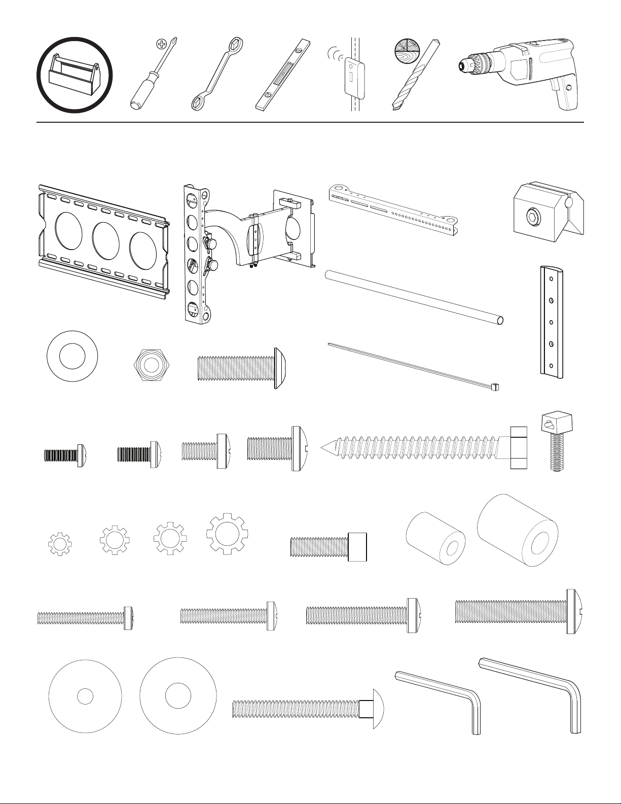
Supplied Parts and Hardware
Before starting assembly verify all parts are included and undamaged If any parts are missing or damaged do not return the item
to your dealer; contact Sanus Customer Service Never use damaged parts!
[06] x 4
[11] x 4
[01] x 1 [02] x 1
[07] x 4
[12] x 4
[13] x 4
[08] x 2
[14] x 4
[03] x 2
[04] x 2
[09] x 10
[15] x 4
[05] x 4
[10] x 1
[16] x 2
[17] x 4M4[18] x 4M5[19] x 4M6[20] x 4
[24] x 4
[29] x 4
[28] x 8
[25] x 4
[21] x 4
[30] x 4
[26] x 4
[22] x 4
7/32 in.
[31] x 1
[23] x 4
[27] x 4
3/16 in.
[32] x 1
6901-100016 <04>
Page 3
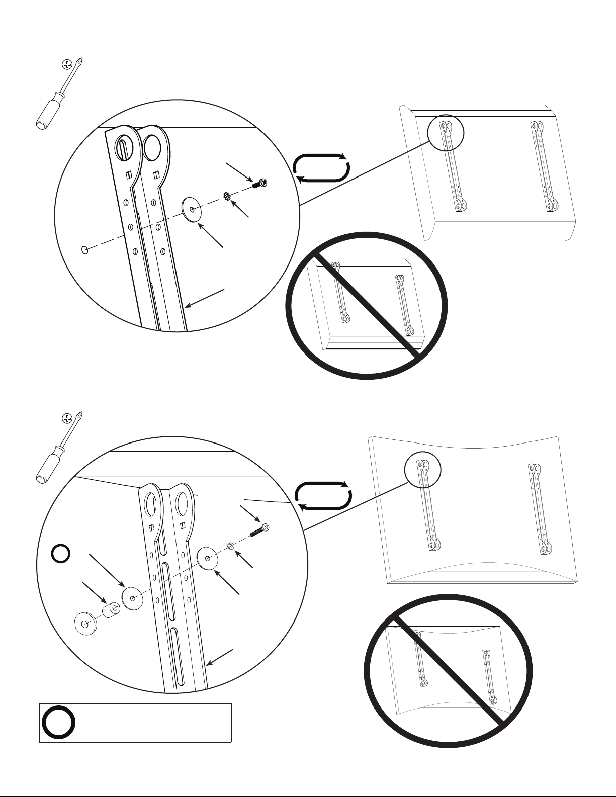
1: Attach Brackets to Monitor
001429.eps
FPM70-Brackets not level
OPT
OPT
For Monitors with a Flat Back
[11], [12],
[13], [14]
[17], [18],
[19], [20]
[28], [29]
[03]
4x
[28]
[22], [23]
For Monitors with a Curved Back or Obstruction
[11], [12],
[13], [14]
[17], [18],
[19], [20]
[28], [29]
[03]
4x
Use washer [28] with M4 or M5
hardware only.
6901-100016 <04>
Page 4

2: Install Vise Assemblies
001438.eps
FPM70-Arm Attachment Detail
001438.eps
FPM70-Arm Attachment Detail
[31]
[05]
[30]
[07]
[03]
4x
NOTE
Do not overtighten the nut [07]. The vise assembly [05] must
rotate freely around the carriage bolt [30].
3: Install Arm Assembly to Monitor
2x
[04]
[04]
[03]
2x
6x
[02]
[03]
[05]
[04]
NOTE
Do not overtighten the fastener in
the vise assemblies [05]. Tighten
only enough to prevent the tubes
[04] from moving.
6901-100016 <04>
Page 5

4: Install Wall Plate
001439.eps
Attach Plate to Wall
3/16 in.
NOTE
This product must only be used with wood studs
spaced 30 - 40 cm (12 - 16 in.) on center.
[01]
NOTE
Do not overtighten the lag bolts [15]. Tighten only
until the washer [06] is pulled rmly against the wall
plate [01]. Periodic maintenance may be required.
[15]
[06]
6901-100016 <04>
Page 6

[32]
5: Attach Arm to Wall Plate
HEAVY! You will need
assistance with this step.
[02]
CAUTION
Avoid potential injuries or property
damage! Ensure the safety bolts [08]
are secure. Periodic maintenance
may be required.
[01]
[08]
6901-100016 <04>
Page 7

[32]
OPT
6: Install Preventer
Install the preventer [10] on the left side if
you want the arm to fold to the left. Install
the preventer on the right side if you want
the arm to fold to the right.
7: Install Cable Management
[16]
Be sure to leave enough slack in the
cables to allow the monitor to move
freely. Use the cable ties [09] and wire
clips [16] to secure the cables to the
brackets [03] and arm [02].
[10]
[21]
[09]
[16]
NOTE
6901-100016 <04>
[09]
[03]
Page 8

8: Adjust Monitor Position
[31]
Adjust Level
[A]
Adjust Left / Right Swivel
[B]
[C]
CAUTION
Avoid potential injuries or property damage! Remove the safety
bracket [B] only to adjust the swivel tension nut [C]. Be sure to replace
the safety bracket after adjusting the swivel tension nut. The hex hole
in the safety bracket must seat over the swivel tension nut.
[B]
6901-100016 <04>
Page 9

Adjust Up / Down Pitch
NOTE
Adjust the pitch tension by tightening or
loosening the tension knobs [D].
[D]
[31]
Extend or Retract Arm
CAUTION
Avoid potential injuries or property damage!
Do not remove the adjustment nut [E];
tighten or loosen only as necessary for easy
arm adjustment.
6901-100016 <04>
[E]
[E]
Page 10

Milestone AV Technologies, Inc. and its affiliated corporations and subsidiaries (collectively, “Milestone”), intend to make this manual accurate and complete. However, Milestone makes no
claim that the information contained herein covers all details, conditions, or variations. Nor does it provide for every possible contingency in connection with the installation or use of this
product. The information contained in this document is subject to change without notice or obligation of any kind. Milestone makes no representation of warranty, expressed or implied,
regarding the information contained herein. Milestone assumes no responsibility for accuracy, completeness or sufficiency of the information contained in this document.
6901-100016 <04>
 Loading...