

Page 1
Assembly Instructions for Model: EFAV-II
Thank you for choosing the Sanus Systems Model EFAV-II. Every effort has
been made to ensure that your Sanus Systems furniture is perfect. If you have
questions or feel that there is a problem of any kind, please contact us at
800-359-5520 or at www.sanus.com. We can quickly help with any issues
regarding assembly or missing parts. Replacement parts for Sanus systems
products purchased through authorized dealers will be shipped directly to you.
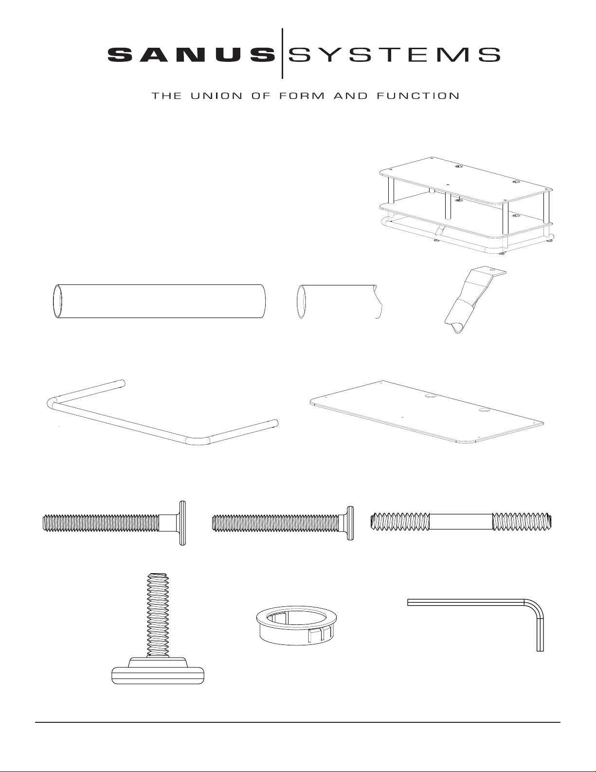
Supplied Parts List: (All threaded fasteners are shown full scale)
8” Pillar - A
Metal Base - D
Top Bolt - F
Qty. 5
Qty. 5
Qty. 1
3” Cope Tube - B
Pan head Bolt - G
Qty. 5
Qty. 4
Angled Center Support - C
Qty. 1
Video Shelf - E
Qty. 2
Shelf Connector - H
Qty. 5
Wire Bushing - J
Qty. 4
Floor Glide - I
Qty. 5
Sanus Systems 2221 Hwy 36 West, Saint Paul, MN 55113 2.01.06 (000009)
Customer Service: 800.359.5520. See complementary Sanus products at www.sanus.com
Allen Key - K
Qty. 1
Page 2
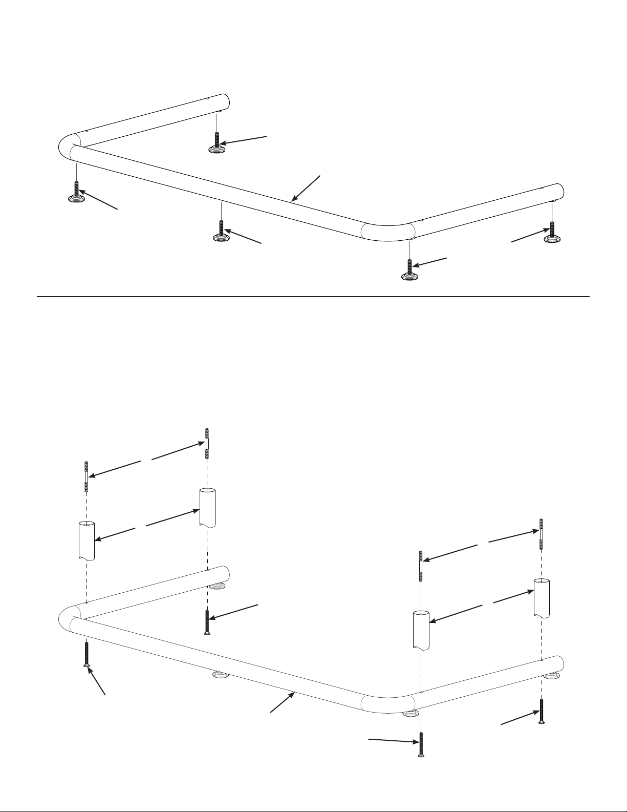
Step 1 - Attach Floor Glides to Metal Frame
Thread the fi ve Floor Glides (I) into the Metal Base (D).
I
I
Diagram 1
D
I
I
Step 2 - Attach 3” Cope Tubes to Metal Base
Thread a Shelf Connector (H) securely into the four 3” Cope Tubes (B).
NOTE: Do not tighten the Pan Head Bolts (G) until the entire EFAV-II is assembled.
Place a Pan Head Bolt (G) through each of the four holes in the Metal Base (D); then, thread them into the four 3” Cope
Tubes (B).
Diagram 2
H
B
I
H
G
G
D
G
B
G
Page 3

Step 3 - Place a Video Shelf on the Metal Base
Align four holes in a Video Shelf (E) with the Shelf Connectors (H) threaded into the 3” Cope T ubes (B) in Step 2; then, place
the Video Shelf onto the 3” Cope Tubes.
Diagram 3
H
B
Step 4 - Secure the Angled Center Support to the Video Shelf
NOTE: Make sure the coped end of the Angled Center Support (C) fi ts over the Metal Base (D).
Attach the Angled Center support (C) to the bottom of the Video Shelf (E) by threading a Pan Head Bolt (G) up through the
Angled Center Support, the Video Shelf, and into an 8” Pillar (A).
A
E
H
B
Diagram 4
E
C
D
G
Page 4

Step 5 - Attach 8” Pillars
By hand, fi rmly thread an 8” Pillar (A) to the four Shelf Connectors (H) protruding through the Video Shelf (E).
Diagram 5
A
H
E
NOTE
If you are installing addditional shelves, refer to the Assembly Instructions for Model: EFVS-II.
Step 6 - Secure Video Shelf to 8” Pillars
Place the Video Shelf (E) on the 8” Pillars (A); then, using the Allen Key (K) and fi ve T op Bolts (F), secure the Video Shelf
to the 8” Pillars.
H
D
Using the same Allen Key (K) tighten the four Pan Head Bolts (G) used to attach the Metal Base (D) to the 3” Cope Tubes
(B) in Step 2.
Diagram 6
F
A
I
D
F
E
F
A
A
I
Page 5

Step 7 - Install Wire Bushings
Snap the four Wire Bushings (J) into the four holes in the Video shelves (E).
Diagram 7
E
J
E
J
Sanus Systems 2221 Hwy 36 West, Saint Paul, MN 55113 2.01.06 (000009)
Customer Service: 800.359.5520. See complementary Sanus products at www.sanus.com
 Loading...