

Page 1
Assembly Instructions for Model: AFV48
Thank you for choosing the Sanus AFV48. If you do not
understand these directions, or have any doubts about
the safety of the installation, please contact Sanus at
800.359.5520 or www.sanus.com. Check carefully to make
sure that there are no missing or defective parts. Our
customer service representatives can quickly assist you
with installation questions and missing or damaged parts.
Replacement parts for products purchased through authorized
dealers will be shipped directly to you. Never use defective
parts. Improper installation may cause damage or serious
injury. Do not use this product for any purpose that is not
explicitly specifi ed by Sanus. Sanus can not be liable for
damage or injury caused by incorrect assembly, or incorrect
use. Please contact Sanus before returning products to the
point of purchase.
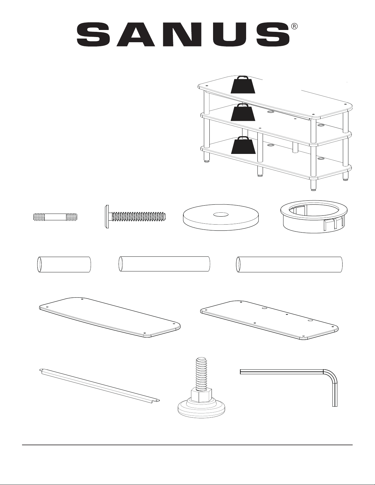
Supplied Parts and Hardware
1/4-20
200 lbs
90.9 kg
200 lbs
90.9 kg
200 lbs
90.9 kg
DO NOT EXCEED
WEIGHT LIMITS!
Shelf Connector - A
Qty. 10
3” Pillar - E
Qty. 6
Front Brace - J
Top Bolt - B
Top Shelf - H
Qty. 1
Qty. 1
Qty. 6
7” Pillar - F
Qty. 4
Spacer - C
Foot - K
Qty. 6
Qty. 2
Grommet - D
Qty. 4
9” Pillar - G
Qty. 6
Bottom & Middle Shelf - I
Qty. 2
Allen Key - L
Qty. 1
Sanus 6436 City West Parkway, Eden Prairie, MN 55344 03.09.12 (6901-100073 <01>)
Customer Service: 800.359.5520. See complementary Sanus products at www.sanus.com
Page 2
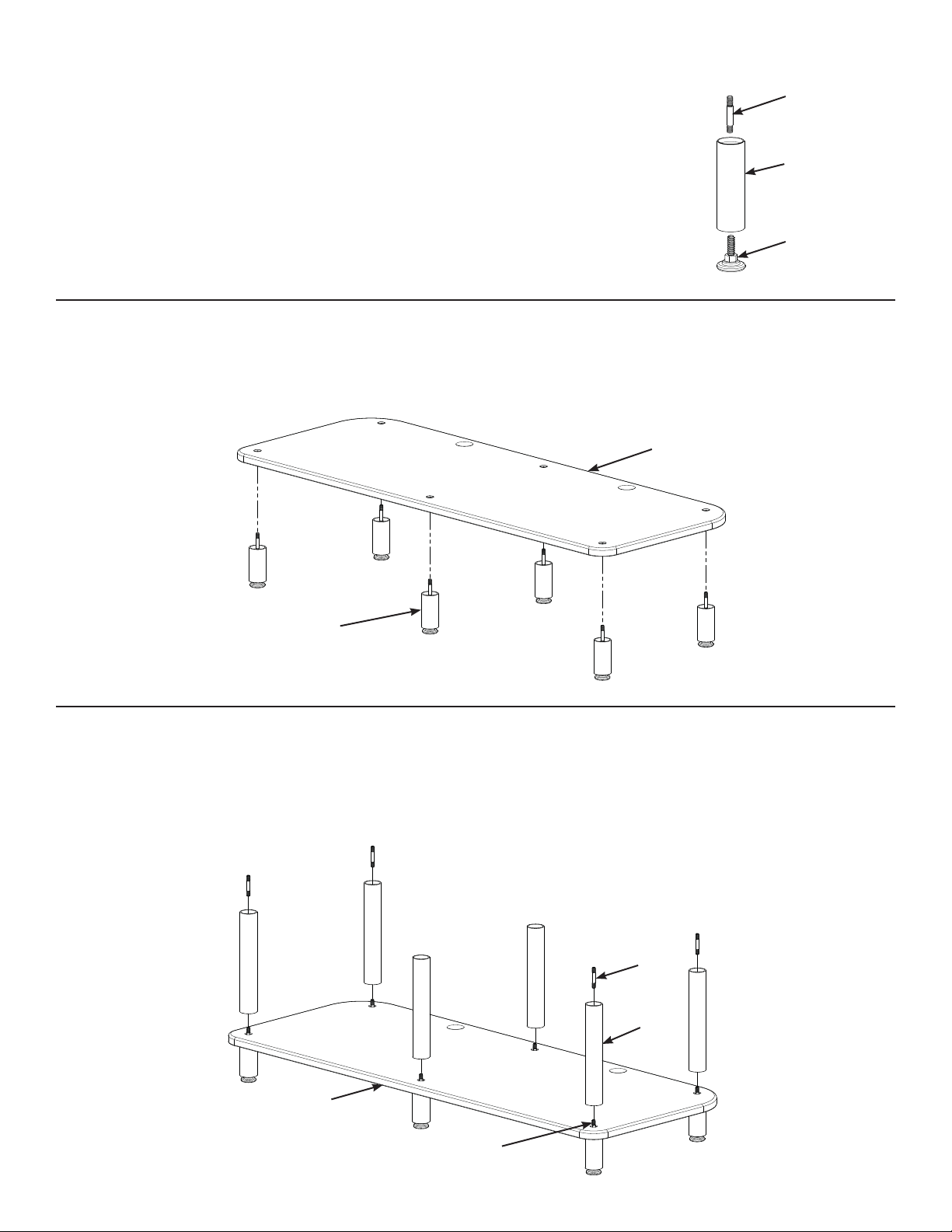
Step 1: Foot Assembly
Diagram 1
Thread a Foot (K) into each 3” Pillar (E).
Thread a Shelf Connector (A) into the other end of the 3” Pillar (E) until tight.
Repeat this process for each remaining 3” Pillar.
Step 2: Add Bottom Shelf
Insert each Foot Assembly from Step 1 through the Bottom Shelf (I) as shown in Diagram 2.
Diagram 2
I
A
E
K
Foot
Assembly
Step 3: Add 9” Pillars
Thread a 9” Pillar (G) onto each exposed Shelf Connector (A) until tight.
Thread a Shelf Connector (A) into the top of the four 9” Pillars (G) as shown in Diagram 3.
Diagram 3
A
G
I
A
Page 3

Step 4: Add Middle Shelf
Place the Middle Shelf (I) on the 9” Pillars (G). A Shelf Connector (A) should be protruding above the Middle Shelf at each
corner.
Place two Top Bolts (B) through the Middle Shelf (I) and thread them into both middle 9” Pillars (G) as shown in Diagram 4.
Using the Allen Key (L), tighten both Top Bolts (B).
Diagram 4
B
Step 5: Add 7” Pillars
Thread and hand tighten a 7” Pillar (F) onto each exposed Shelf connector (A).
I
A
G
Press a Grommet (D) into each wire management hole in the Bottom and Middle Shelf (I) as shown in Diagram 5.
Diagram 5
F
A
I
I
D
D
Page 4

Step 6: Add Top Shelf
Place the Front Brace (J) on the two front 7” Pillars (F) as shown in Diagram 6 and Detail A.
Place the Top Shelf (H) (with its curved edge towards the front) on the Front Brace (J), and 7” Pillars (F) as shown in
Diagram 6.
Insert two Top Bolts (B) through the holes in the Top Shelf (H), Front Brace (J) and two front 7” Pillars (F) as shown in
Diagram 6 and Detail A.
Place a Spacer (C) on both rear 7” Pillars (F) as shown in Diagram 6 and Detail B.
Insert two Top Bolts (B) through the holes in the Top Shelf (H), two Spacers (C) and two rear 7” Pillars (F) as shown in
Diagram 6 and Detail B
Use the Allen Key (L), tighten the four Tops Bolts (B).
Diagram 6
H
J
F
Detail A
B
Detail B
B
H
C
F
Curved edge
towards front
Sanus 6436 City West Parkway, Eden Prairie, MN 55344 03.09.12 (6901-100073 <01>)
Customer Service: 800.359.5520. See complementary Sanus products at www.sanus.com
 Loading...