

Page 1
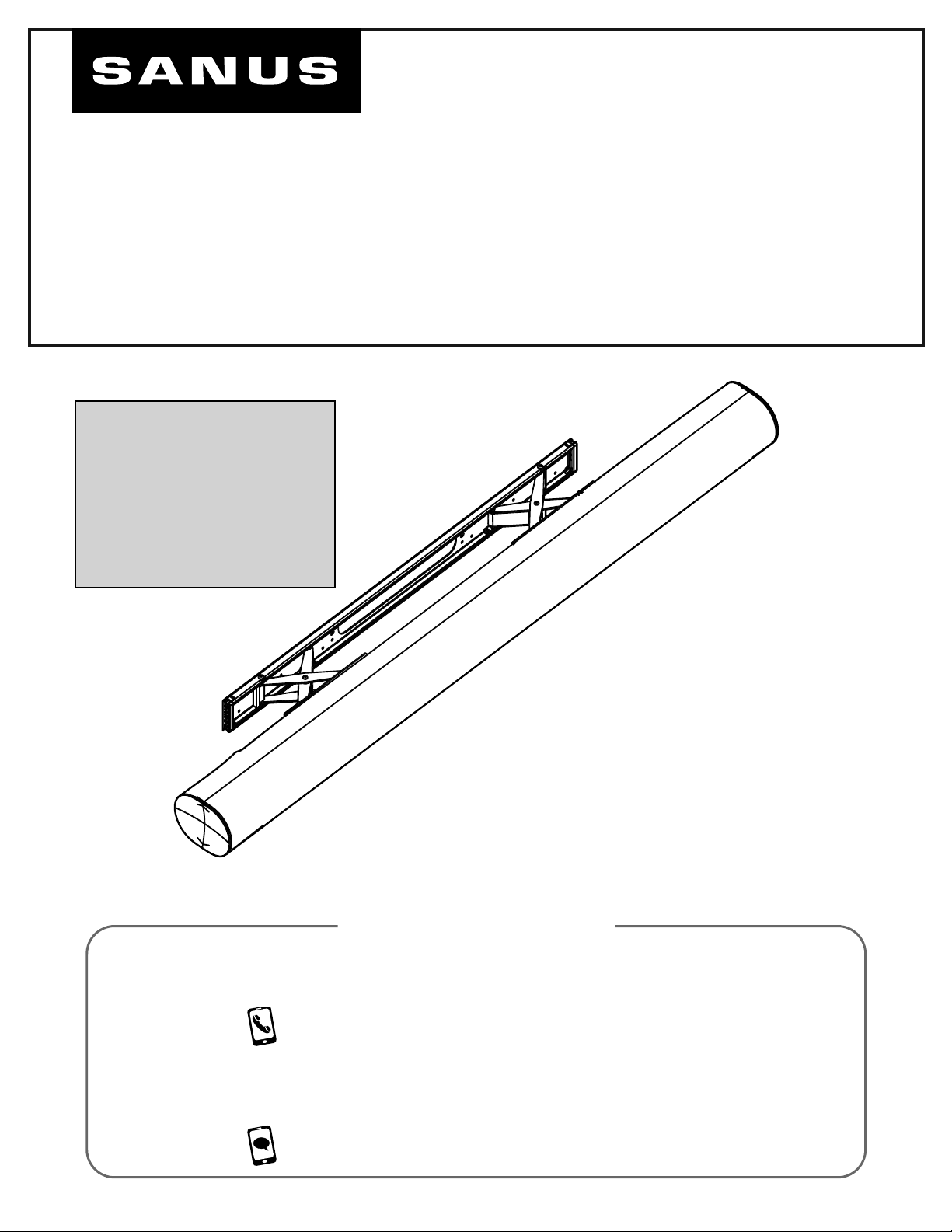
WSSAWM1
SOUNDBAR WALL MOUNT
DESIGNED FOR
Sonos® Arc
INSTRUCTION MANUAL
This mount is designed
to support Sonos® Arc™
soundbar and works with
SANUS and other TV
mount brands.
™
WE’RE HERE TO HELP
If you have any questions along the way, our US-based
install experts are standing by to help.
Call us at: US: 800-359-5520
UK: 0800 056 2853
EMEA: +31 (0) 495 580 852
Or, chat at: US: SANUS.com/chatSP
Page 2
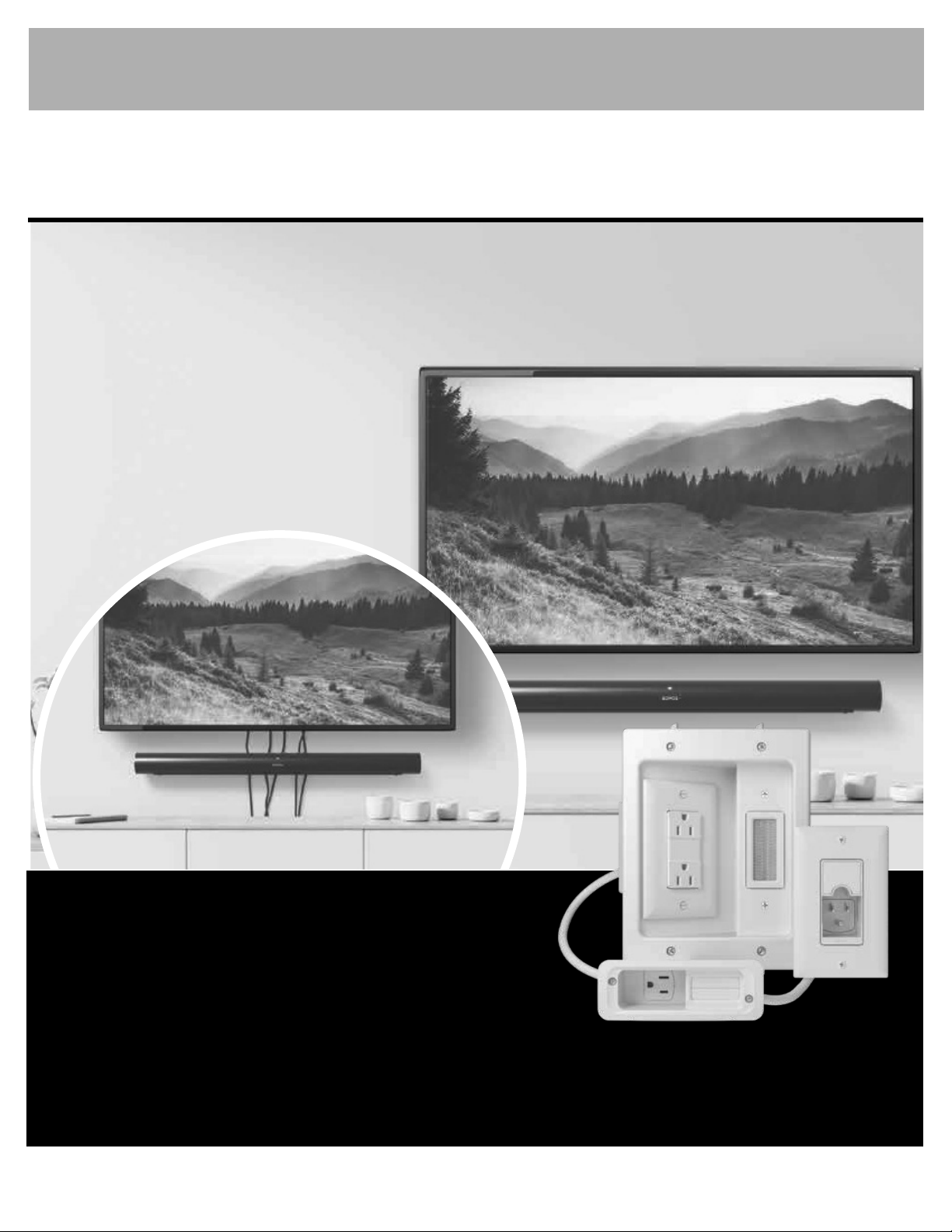
YOU’D LOVE THIS KIT!
Complete your installation by hiding your cables with the
In-Wall Power Kit for Soundbar + Mounted TV
• Works perfectly with the
Sonos® Arc™ Wall Mount
• Hides all cabling behind the wall
• Can power multiple devices
• Safe and easy to install with no
electrician needed
BEFORE
IN-WALL
POWER KIT
FOR SOUNDBAR + MOUNTED TV
Model WSIWPSB1-W1
Check out SANUS.com, SONOS.com, or Amazon.com!
2
Available in the U.S. only
Page 3
IMPORTANT SAFETY INSTRUCTIONS. READ ENTIRE MANUAL PRIOR TO USE. SAVE THESE INSTRUCTIONS
Before getting started, let’s make sure this product is perfect for you!
CAUTION: To avoid potential personal injuries and property damage:
This soundbar mount is only designed for use with the Sonos® Arc™ speaker.
•
Please read through these instructions completely to be sure you’re comfortable with this easy install process.
•
Do not use this product for any purpose not explicitly specified by manufacturer.
•
Manufacturer is not responsible for damage or injury caused by incorrect assembly or use.
•
If you do not understand these instructions or have doubts about the safety of the installation, assembly or use of this product,
•
contact Customer Service.
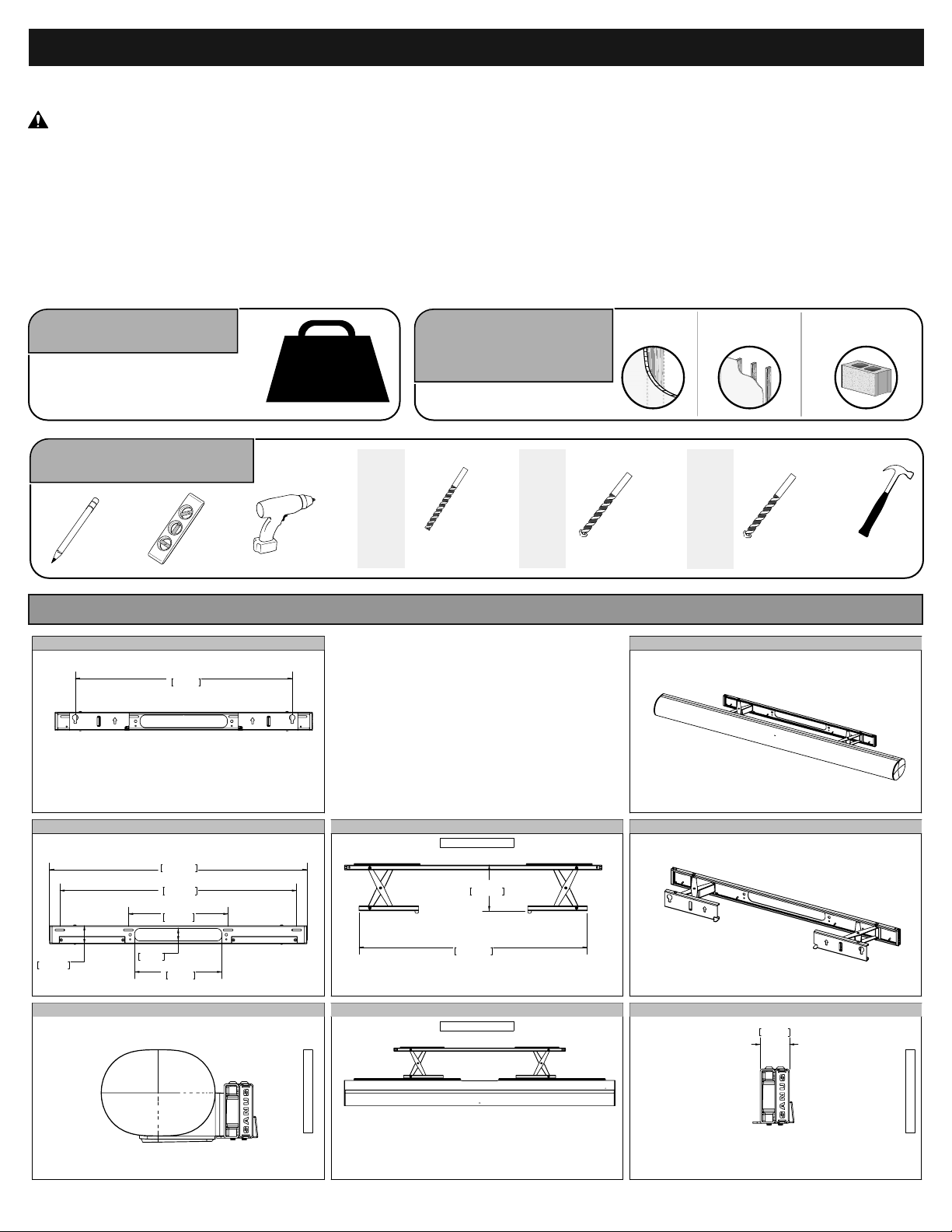
Weight Limit
DO NOT EXCEED
Tools Needed
23.98in
609mm
Level
Pencil
DIMENSIONS IN. [MM]
TV INTERFACE
14 lbs.
(6.4 kg)
Electric Drill
Wall
Construction
13/32 in.
(10 mm)
Install
Drywall
Drill Bit
Install
Wood Stud
Dry wall Wood stud
1/8 in.
(3 mm)
Wood
Drill Bit
Install
Concrete
Drill Bit
3-D
Concrete block/
Solid concrete
13/32 in.
(10 mm)
Concrete
Hammer
50.8mm
WALL PLATE
2.00in
FULLY ASSEMBLED MOUNT
1.38in
35mm
28.45in
722.6mm
26.16in
664.4mm
11.02in
280mm
9.65in
245mm
TOP VIEW - TV MOUNTED
WALL IS ON RIGHT
WALL IS ON TOP
5.05in
128.4mm
25.21in
640.4mm
TOP VIEW
WALL IS ON TOP
SIMULATED 55"
FLAT SCREEN TV
3-D
SIDE VIEW
1.08in
27.4mm
WALL IS ON RIGHT
3
Page 4
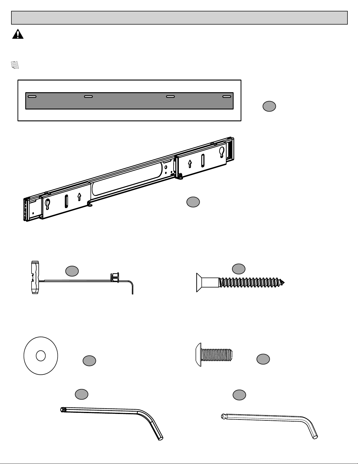
SUPPLIED PARTS AND HARDWARE
WARNING:
This product contains small items that could be a choking hazard if swallowed.
Before starting assembly, verify all parts are included and undamaged. If any parts are missing or damaged,
DO NOT return the damaged item to your dealer; Contact Sanus (See back page). Never use damaged parts!
NOTE: Not all hardware included in this kit will be used.
Wall Template
(qty. 1)
1
Soundbar Mount
(qty. 1)
2
Drywall/Concrete Anchors
(qty. 4)
3
M4/M5 Washer
(qty. 4)
5
5/64 Hex Key
7
(qty. 1)
Screw
(qty. 4)
4
M5 x 14 mm Screw
6
M3 Ball Hex Key
8
(qty. 1)
(qty. 2)
4
Page 5
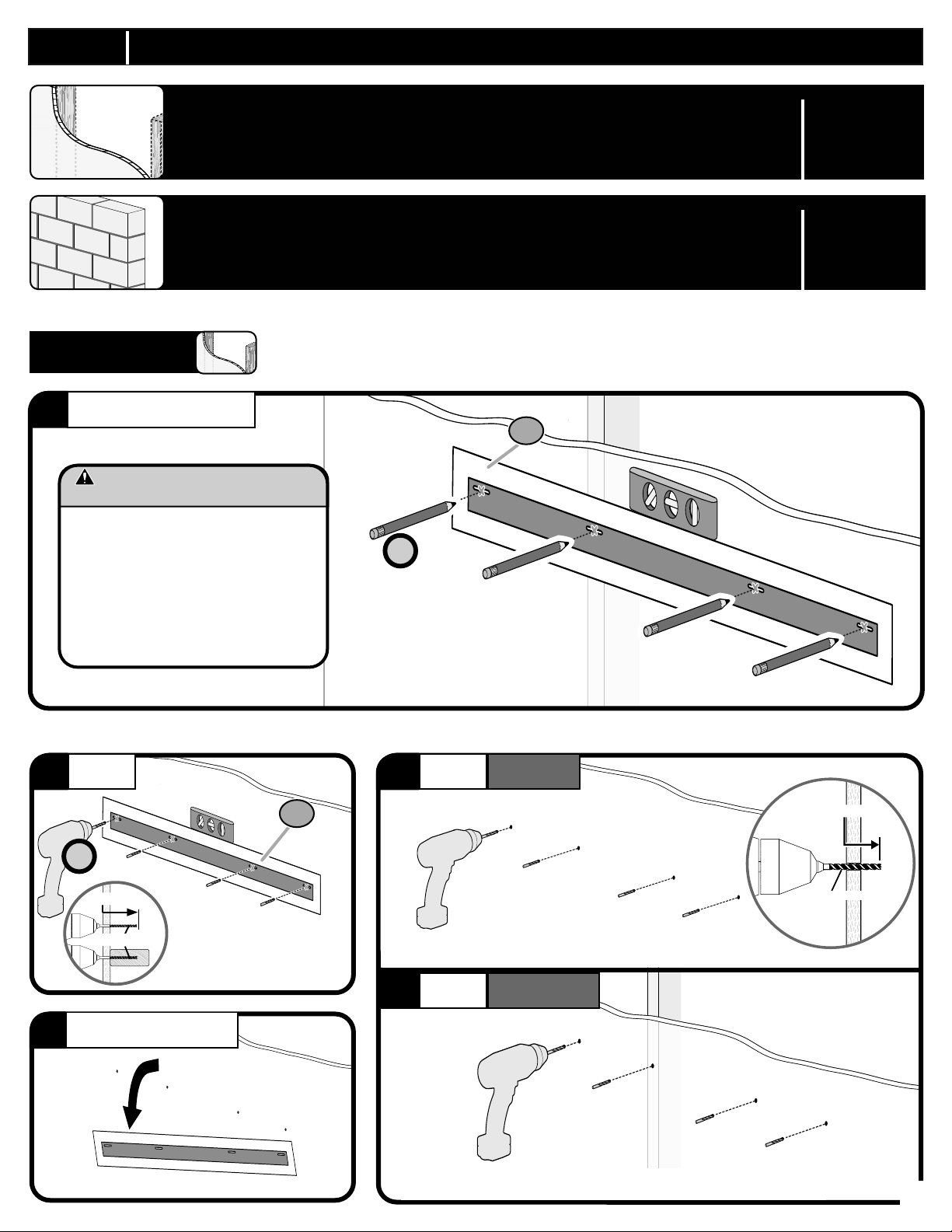
STEP 1 ATTACH SOUNDBAR MOUNT TO WALL
Drywall Installation /
Drywall + Wood Stud Installation
Page 5
Concrete Block/
Solid Concrete Installation
STEP 1A
POSITION TEMPLATE
1
CAUTION: Avoid potential personal
injury or property damage!
● Drywall covering the wall must not
exceed 1/2 in. (1.2 cm).
● Minimum wood stud size:
nominal 2 x 4 in. (5.1 x 10.2 cm)
actual 1 ½ x 3 ½ in. (3.8 x 8.9 cm)
● Stud centers must be verified
● IMPORTANT: Ensure wall plate is level
before drilling.
Page 7
Drywall Installation
1
4X
DRILL
2
4X
3 in. (76.2 mm)
1/8 in. (3.0 mm)
REMOVE TEMPLATE
3
1
Drill 1/8 in. (3.0 mm) pilot holes to
verify wall.
DRILL
4a
If pilot hole is located in drywall, drill 13/32 in. (10 mm) hole.
DRILL
4b
If pilot hole is located on a stud, proceed to Step 5.
DRYWALL
WOOD STUD
1 in. (25 mm)
13/32 in. (10 mm)
5
Page 6

INSERT DRYWALL/CONCRETE ANCHORS
5
IMPORTANT:
• Use anchors for drywall and concrete only. Do not use with wood studs.
• If pilot hole is located on a stud, anchor is not needed. Screw directly into stud. Then use anchors for remaining screws in drywall.
5a
3
5b
5c 5d
3
3
3
SECURELY TIGHTEN
6
2
5
4
6
Page 7
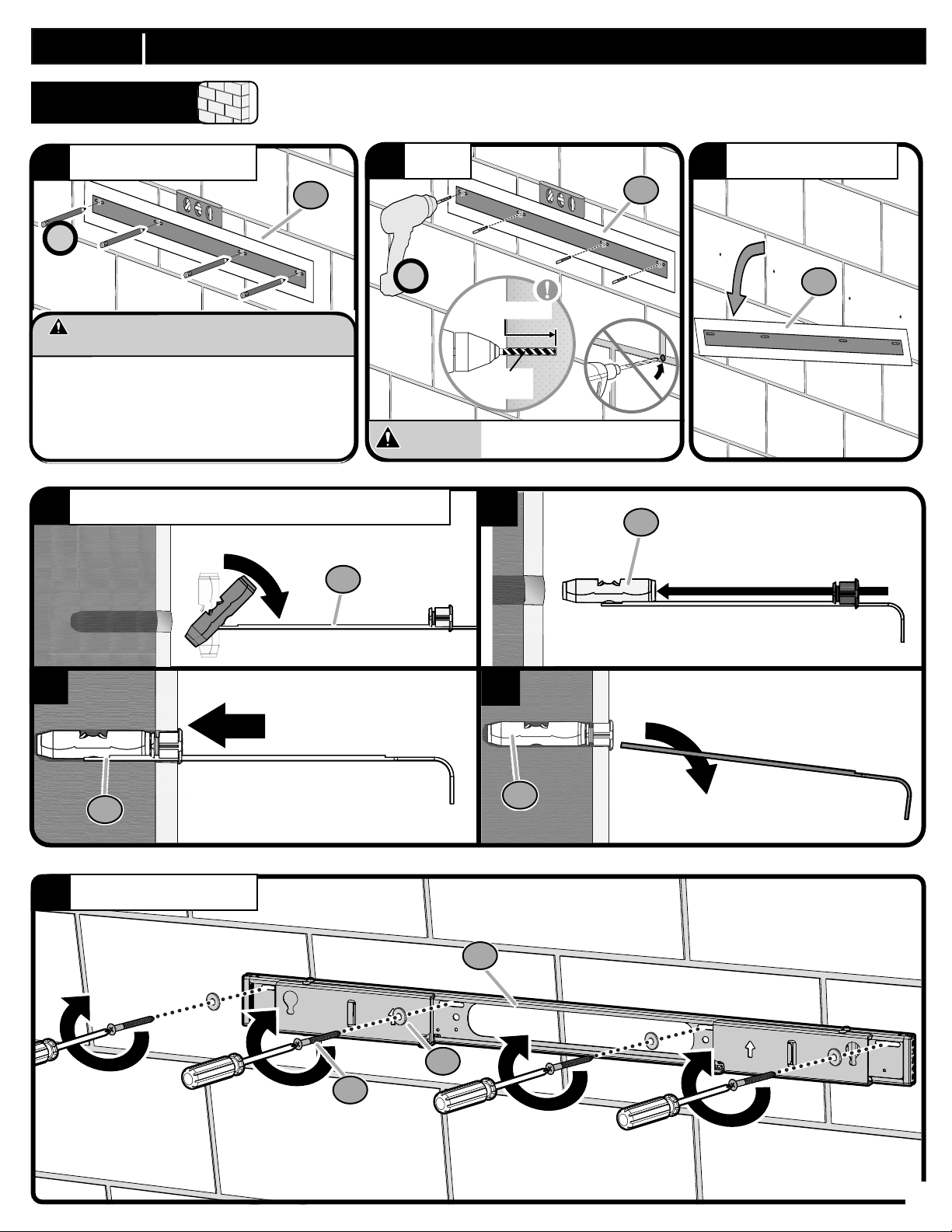
STEP 1C ATTACH SOUNDBAR MOUNT TO WALL
STEP 1C
POSITION TEMPLATE
1
4X
CAUTION: Avoid potential personal injury or
property damage!
● Minimum solid concrete thickness: 8 in. (20.3 cm)
● Minimum concrete block size: 8 x 8 x 16 in. (20.3 x
20.3 x 40.6 cm)
● Minimum horizontal space between fasteners: 16
in. (40.6 cm)
4a
INSERT DRYWALL/CONCRETE ANCHORS
Concrete Installation
1
DRILL
2
4X
CAUTION:
3 in. (7.6 cm)
13/32 in.
(10 mm)
Never drill into the mortar
between blocks.
4b
REMOVE TEMPLATE
REMOVE TEMPLATE
3
3
1
1
3
4c
5
3
4d
3
3
SECURELY TIGHTEN
2
5
4
7
Page 8
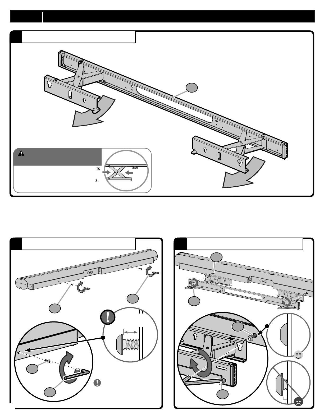
STEP 2 ATTACH SOUNDBAR TO SOUNDBAR MOUNT
OPEN MOUNT BRACKETS
1
2
CAUTION: Avoid potential
personal injury or property damage!
The brackets contain potential pinch points
during operation. Keep fingers away from
pinch points when retracting the brackets.
(see arrows)
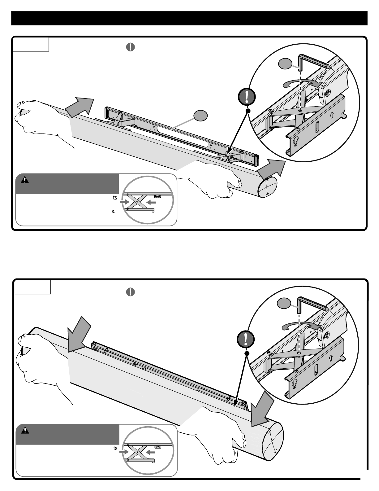
INSERT SOUNDBAR SCREWS
2
ATTACH SOUNDBAR AND SECURELY TIGHTEN
3
6
8
8
6
≈ 1/4 in.
(6.35 mm)
6
6
IMPORTANT:
8
8
Partially insert the bolt leaving
a 1/8”-1/4” gap between the
bolt head and speaker.
8
Page 9
ADJUSTMENTS
RETRACT
CAUTION: Avoid potential
personal injury or property damage!
The brackets contain potential pinch points
during operation. Keep fingers away from
pinch points when retracting the brackets.
(see arrows)
IMPORTANT:
Tighten to a locked position if desired.
Otherwise, keep tension loose for free movement.
2
7
EXTEND
CAUTION: Avoid potential
personal injury or property damage!
The brackets contain potential pinch points
during operation. Keep fingers away from
pinch points when retracting the brackets.
(see arrows)
IMPORTANT:
Tighten to a locked position if desired.
Otherwise, keep tension loose for free movement.
7
9
Page 10

101112
Page 11

Page 12

Español
¡TE ENCANTARÍA ESTE KIT! IN-WALL POWER KIT
PARA BARRA DE SONIDO + TV FIJADO A LA PARED
COMPLETE LA INSTALACIÓN OCULTANDO LOS CABLES CON EL IN-WALL POWER
KIT PARA BARRA DE SONIDO + TV FIJADO A LA PARED
• Funciona perfectamente con el soporte de pared Sonos® Arc
™
• Oculta todo el cableado tras la pared
• Proporciona alimentación a múltiples dispositivos
• Seguro y fácil de instalar sin necesidad de llamar a un electricista
¡VISITE SANUS.COM, SONOS.COM, BESTBUY.COM O AMAZON.COM!
Disponible solo en EE. UU.
ES
INSTRUCCIONES DE SEGURIDAD IMPORTANTES. LEA TODO EL MANUAL ANTES DEUTILIZAR EL PRODUCTO POR PRIMERA VEZ. CONSERVE ESTAS INSTRUCCIONES
Esta montura está diseñada para la barra de sonido Sonos® Arc™ y funciona con SANUS y otras marcas de monturas de TV.
¡Antes de empezar, asegúrese de que este es el producto adecuado para usted!
PRECAUCIÓN: Para evitar posibles lesiones personales y daños materiales:
• Esta montura para barra de sonido está diseñada solo para usarse con el altavoz Sonos® Arc™.
• Lea atentamente estas instrucciones para asegurarse de que está familiarizado conel sencillo proceso de instalación.
• No utilice este producto para ningún otro propósito que no sea el especificado explícitamente por el fabricante.
• El fabricante no se responsabiliza de ningún daño o lesión resultante del montaje incorrecto o el uso indebido del producto.
• Si no entiende las instrucciones o si tiene dudas acerca de la seguridad de la instalación, el montaje o el uso del producto, póngase en contacto con
el servicio deatención al cliente.
NO EXCEDA
el límite de peso
6,4 kg
(14 lb.)
13/32 in.
(10 mm)
hormigón
MartilloBroca
Herramientas
necesarias
Lápiz
Nivel
Taladro eléctrico
yeso
Paneles de
Broca
13/32 in.
(10 mm)
Montante
de madera
Broca
1/8 in.
(3 mm)
madera
Hormigón
DIMENSIONES
PIEZAS Y ELEMENTOS DE MONTAJE SUMINISTRADOS
PÁGINA 3
PÁGINA 4
Antes de comenzar a montar la unidad, verifique que dispone de todas las piezas yque se encuentran en buen estado. Si no dispone de todas
las piezas o alguna está dañada, NO devuelva el elemento defectuoso al distribuidor. Póngase en contacto con el servicio de atención al
cliente. Nunca utilice piezas en mal estado.
ADVERTENCIA:
RIESGO DE ATRAGANTAMIENTO. Este producto contiene piezas pequeñas que, en caso de ser tragadas, podrían causar
asfixia.
NOTA: No se utilizarán todos los elementos de montaje incluidos en este kit.
PASO 1 FIJAR A LA PARED LA MONTURA PARA BARRA DE SONIDO
PÁGINA 5
Instalación de paneles de yeso /
Instalación de paneles de yeso + postes de madera
Instalación en paredes de hormigón sólido o en bloques de hormigón
Página 5
Página 7
Page 13

1A
COLOCAR LA PLANTILLA
1
Instalación de paneles de yeso
PÁGINA 5
PRECAUCIÓN: Evite posibles lesiones físicas y daños materiales. • El yeso que recubre la pared no debe exceder los 1,2 cm (1/2 pulg.). • Tamaño
mínimo del montante de madera: común 5,1 x 10,2 cm (2 x 4 pulg.) nominal 3,8 x 8,9 cm (1 ½ x 3 ½ pulg.) • Debe comprobar los montantes centrales.
• Importante: asegúrese de que la plantilla de la pared esté nivelada antes de perforar.
TALADRAR
2
Taladre orificios de prueba de 1/8 pulg. (3,0 mm) para comprobar el material de la pared.
RETIRAR LA PLANTILLA
3
TALADRAR
4
4a. Si el orificio guía está en un panel de yeso, taladre un orificio de 13/32 pulg. (10 mm).
4b. Si el orificio piloto está en un montante, continúe con el Paso 5.
INSERTAR ANCLAJES
5
IMPORTANTE:
• Use anclajes únicamente para paneles de yeso y hormigón. No se deben utilizar en montantes de madera.
• Si el orificio piloto está ubicado en un montante, no se necesita anclaje. Atornille directamente en el montante. Luego use anclajes
para los tornillos restantes en paneles de yeso.
APRETAR FIRMEMENTE
6
1B
Instalación en paredes de hormigón sólido o en bloques de hormigón
PÁGINA 7
PRECAUCIÓN: Evite posibles lesiones físicas y daños materiales.
• Espesor mínimo del hormigón: 20,3 cm (8 pulg.). • Tamaño mínimo del bloque de hormigón: 20,3 x 20,3 x 40,6 cm (8 x 8 x 16 pulg.). • Espacio
horizontal mínimo entre los elementos de sujeción: 40,6 cm (16 pulg.).
COLOCAR LA PLANTILLA
1
TALADRAR ORIFICIOS EN LOS CENTROS DE LOS MONTANTES
2
NOTA: Nunca perfore el cemento que une los bloques
RETIRAR LA PLANTILLA
3
INSERTAR ANCLAJES
4
APRETAR FIRMEMENTE
5
PASO 2 FIJAR A LA PARED LA MONTURA PARA BARRA DE SONIDO
1
ABRIR LOS SOPORTES DE LA MONTURA
PÁGINA 8
PRECAUCIÓN: ¡Evite posibles lesiones personales o daños materiales! Los soportes del televisor contienen puntos de compresión
potenciales que podrían lastimarlo durante la instalación. Mantenga los dedos alejados de los puntos de compresión cuando repliegue el
televisor (ver flechas).
2
INSERTAR LOS TORNILLOS DE LA BARRA DE SONIDO
IMPORTANTE: Inserte parcialmente el perno dejando un hueco de 1/8pulg. - 1/4pulg. entre la cabeza y el altavoz.
3
FIJAR LA BARRA DE SONIDO Y APRETAR FIRMEMENTE
AJUSTES
PÁGINA 9
EXTENDER/RETRAER
IMPORTANTE: apriete hasta que quede fijo si lo desea. Si no, déjelo un poco suelto para que pueda moverse.
PRECAUCIÓN: ¡Evite posibles lesiones personales o daños materiales! Los soportes del televisor contienen puntos de compresión
potenciales que podrían lastimarlo durante la instalación. Mantenga los dedos alejados de los puntos de compresión cuando repliegue el
televisor (ver flechas).
13
Page 14

Français
FR
Ce support est conçu pour prendre en charge la barre de son Sonos® Arc™ et fonctionne avec SANUS et d’autres marques de support pour téléviseur.
INFORMATIONS IMPORTANTES CONCERNANT LA SÉCURITÉ – CONSERVEZ CES INSTRUCTIONS – VEUILLEZ LIRE ATTENTIVEMENT LE MANUEL AVANT D'UTILISER CE PRODUIT
Avant de commencer, assurons-nous que ce support vous convient parfaitement!
ATTENTION: Évitez les risques de blessures corporelles ou de dommages matériels!
• Ce support pour barre de son est uniquement conçu pour être utilisé avec l’enceinte Sonos® Arc™.
• Ce produit est conçu pour une utilisation sur des montants en bois, des murs en béton plein et en bloc de béton - NE l’installez PAS seul sur
une cloison sèche.
• Le mur doit pouvoir supporter cinq fois le poids total du téléviseur et du support.
• N’utilisez pas ce produit à d’autres fins que celles spécifiées par le fabricant.
• Le fabricant n’est pas responsable des blessures ou des dommages causés par une mauvaise utilisation ou un montage incorrect.
Poids limite
6,4 kg
(14 lb.)
13/32 in.
(10 mm)
Béton
MarteauForet
PAGINA 3
Outils requis
DIMENSIONS
Crayon
Niveau
Perceuse
electrique
Installation de
cloisons sèches
Foret
13/32 in.
(10 mm)
Installation de
montant en bois
Foret
1/8 in.
(3 mm)
madera
béton
Installation de
PIÈCES ET QUINCAILLERIE FOURNIES
AVERTISSEMENT : Ce produit contient de petites pièces qui peuvent représenter un risque d'étouffement si elles sont avalées.
Avant de commencer l’assemblage, assurez-vous qu’il ne manque aucune pièce et qu’elles ne sont pas endommagées. Si une pièce est
manquante ou endommagée, contactez le service à la clientèle et non le détaillant. N’utilisez jamais de pièces endommagées!
REMARQUE: Les pièces fournies ne doivent pas nécessairement être toutes utilisées.
ÉTAPE 1 FIXEZ LE SUPPORT POUR BARRE DE SON AU MUR
Montage sur cloison sèche /
Installation de cloisons sèches et de colombages en bois
Installation de béton coulé ou de blocs de béton
Page 5
Page 7
PAGINA 4
PAGINA 5
14
Page 15

1A
POSITIONNEZ LE GABARIT
1
Montage sur cloison sèche
PAGE 5
ATTENTION : Évitez les risques de blessures corporelles ou de dommages matériels! • L’épaisseur du revêtement de cloison sèche ne
doit pas excéder 1,2 cm (1/2po). • Taille minimum des montants en bois: nominale 5,1 x 10,2 cm (2 x 4 po), réelle 3,8 x 8,9 cm (1 ½ x 3 ½ po). • Les
centres des montants doivent être vérifiés.
PERCER
2
• Important: assurez-vous que le gabarit mural est de niveau avant de percer.
Percez des avant-trous de 3,0mm (1/8 pouce) pour vérifier le mur.
RETIREZ LE GABARIT
3
PERCER
4
4a. Si l’avant-trou est situé dans la cloison sèche, percez un trou de 10mm (13/32pouce).
4b. Si l’avant-trou est situé sur un montant en bois, passez à l’étape 5).
INSÉREZ LES CHEVILLES
5
IMPORTANT: Utilisez des ancrages pour cloison sèche et béton uniquement. Ne les utilisez pas avec des montants de bois.
Si le trou pilote est situé sur un montant, l'ancrage n'est pas nécessaire. Visser directement dans le goujon. Ensuite, utilisez des ancrages pour
les vis restantes dans les cloisons sèches.
SERREZ CORRECTEMENT
6
1B
ATTENTION : Évitez les risques de blessures corporelles ou de dommages matériels! • Épaisseur minimale du béton solide: 20,3 cm (8 po) • Dimension
minimale du bloc de béton: 20,3 x 20,3 x 40,6 cm (8 x 8 x 16 po)
POSITIONNEZ LE GABARIT
1
PERCEZ DES TROUS AU CENTRE DES MONTANTS
2
NOTA: Prenez soin de ne jamais percer dans le mortier entre les blocs.
RETIREZ LE GABARIT
3
INSÉREZ LES CHEVILLES
4
SERREZ CORRECTEMENT
5
ÉTAPE 2 FIXEZ LE SUPPORT POUR BARRE DE SON AU MUR
1
OUVREZ LES PATTES DE FIXATION
ATTENTION : Évitez les risques potentiels de blessures corporelles ou de dommages matériels! Les pattes de fixation pour téléviseur contiennent des points
de pincement potentiels lors de leur utilisation. Éloignez vos doigts des points de pincement lorsque vous rétractez le téléviseur (voir les flèches).
2
INSÉREZ LES VIS DE LA BARRE DE SON
IMPORTANT: Insérez partiellement le boulon, en laissant un espace de 1/8 à 1/4pouce entre la tête de boulon et l’enceinte.
3
FIXEZ LA BARRE DE SON ET SERREZ CORRECTEMENT
RÉGLAGES
EXTENSION / RÉTRACTION
Installation de béton coulé ou de blocs de béton
PAGE 7
PAGE 8
PAGE 9
IMPORTANT: Serrez en position bloquée si vous le souhaitez. Autrement, laissez la tension lâche pour permettre le mouvement.
ATTENTION : Évitez les risques potentiels de blessures corporelles ou de dommages matériels! Les pattes de fixation pour téléviseur contiennent des points
de pincement potentiels lors de leur utilisation. Éloignez vos doigts des points de pincement lorsque vous rétractez le téléviseur (voir les flèches).
15
Page 16

Deutsch
DE
Diese Halterung wurde für die Soundbar Sonos® Arc™ entwickelt und funktioniert mit SANUS und anderen Marken für TV-Halterungen.
WICHTIGE SICHERHEITSHINWEISE – BEWAHREN SIE DIESE HINWEISE SORGFÄLTIG AUF – LESEN SIE VOR DEM GEBRAUCH
DES PRODUKTS BITTE DAS GESAMTE HANDBUC
Stellen Sie vor Montagebeginn sicher, dass diese Halterung für Sie geeignet ist!
VORSICHT: Vermeiden Sie Verletzungen und Sachschäden!
• Diese Soundbar-Halterung eignet sich nur für die Verwendung mit dem Lautsprecher Sonos® Arc™
• Dieses Produkt ist für die Montage an Wänden mit Holzträgern oder an Massivbeton- und Betonblockwänden bestimmt. NICHT an einer
reinen Gipskartonwand montieren
• Die Wand muss das Fünache des Gesamtgewichts des Fernsehers und der Halterung tragen können
• Verwenden Sie dieses Produkt nur für die vom Hersteller ausdrücklich angegebenen Zwecke
• Der Hersteller haftet nicht für Schäden oder Verletzungen, die durch unsachgemäße Montage, unsachgemäßen Zusammenbau oder
unsachgemäße Verwendung verursacht wurden
Zulässiges
Höchstgewicht
Erforderlichen
Werkzeuge
Stift
6,4 kg
(14 lb.)
Wasserwaage
Elektrobohrer
installieren
Trockenbau
13/32 in.
(10 mm)
Bohreinsatz
Holzbolzen
installieren
Bohreinsatz
1/8 in.
(3 mm)
Beton
installieren
Bohreinsatz
13/32 in.
(10 mm)
für Stein
Hammer
ABMESSUNGEN
IM LIEFERUMFANG ENTHALTENE TEILE UND BEFESTIGUNGSMATERIAL
SEITE 3
SEITE 4
WARNUNG: Dieses Produkt enthält kleine Teile, die beim Verschlucken zum Erstickungstod führen können.
Prüfen Sie vor Montagebeginn, ob alle Teile vorhanden und unbeschädigt sind. Falls Teile fehlen oder beschädigt sind, bringen Sie das Produkt nicht zum Händler zurück, sondern
wenden Sie sich an den Kundendienst. Verwenden Sie niemals beschädigte Teile!
HINWEIS: Es wird nicht das gesamte mitgelieferte Befestigungsmaterial verwendet.
SCHRITT 1 BEFESTIGEN DER SOUNDBAR-HALTERUNG AN DER WAND
Gipskartonplatten-Option
Installation von Trockenbau- und Holzpfosten
Massivbeton- oder Betonblock
Seite 5
Seite 7
SEITE 5
16
Page 17

1A
SCHABLONE ANSETZEN
1
Vermeiden Sie Verletzungen und Sachschäden! Die Gipsschicht der Wand muss mindestens 1,2 mm (1/2") betragen.
BOHREN
2
Gipskartonplatten-Option
SEITE 5
Bohren Sie 1/8Zoll (3,0mm) tiefe Vorbohrungen, um die Wand zu überprüfen.
SCHABLONE ENTFERNEN
3
BOHREN
4
4a. Wenn sich die Vorbohrung im Trockenbau befindet, bohren Sie ein Loch von 13/32Zoll (10mm).
4b. Wenn sich die Vorbohrung auf einem Holzbalken befindet, fahren Sie mit Schritt 5 fort.
DÜBEL EINSETZEN
4
WICHTIG: Verwenden Sie Dübel nur für Trockenbau und Beton. Verwenden Sie keine Dübel bei Holzbalken.
Befindet sich das Pilotloch an einem Bolzen, wird kein Anker benötigt. Direkt in den Bolzen einschrauben. Verwenden Sie dann Anker für die
verbleibenden Schrauben im Trockenbau.
FEST ANZIEHEN
5
1B
Massivbeton- oder Betonblock
VORSICHT: Vermeiden Sie Verletzungen und Sachschäden!
● Mindestdicke der Massivbetonwand: 203 mm (8")
● Mindestmaße des Betonblocks: 203 x 203 x 406 mm (8 x 8 x 16")
SCHABLONE ANSETZEN
1
LÖCHER IN DIE BALKENMITTEN BOHREN
2
SCHABLONE ENTFERNEN
3
DÜBEL EINSETZEN
4
FEST ANZIEHEN
5
SCHRITT 2 BEFESTIGEN DER SOUNDBAR-HALTERUNG AN DER WAND
1
ANSCHLUSSPLATTEN ÖFFNEN
VORSICHT: Vermeiden Sie mögliche Verletzungen und Sachschäden! An manchen Stellen der TV-Anschlussplatten besteht bei der
Benutzung Einklemmgefahr. Halten Sie die Finger von diesen Stellen fern, wenn Sie den Fernseher zurückziehen. (siehe Pfeile)
2
SOUNDBAR-SCHRAUBEN EINSETZEN
WICHTIG: Führen Sie die Schraube teilweise ein und lassen Sie einen Spalt von 1/8–1/4Zoll zwischen Schraubenkopf und Lautsprecher.
3
SOUNDBAR BEFESTIGEN UND SICHER FESTZIEHEN
EINSTELLUNGEN
AUSZIEHEN/EINFAHREN
SEITE 7
SEITE 8
SEITE 9
WICHTIG: Ziehen Sie sie gegebenenfalls in einer verriegelten Position fest. Lassen Sie sie andernfalls unarretiert, damit sie frei beweglich
ist.
VORSICHT: Vermeiden Sie mögliche Verletzungen und Sachschäden! An manchen Stellen der TV-Anschlussplatten besteht bei der
Benutzung Einklemmgefahr. Halten Sie die Finger von diesen Stellen fern, wenn Sie den Fernseher zurückziehen. (siehe Pfeile)
17
Page 18

Nederlands
NL
Deze bevestiging is ontworpen ter ondersteuning van de Sonos® Arc™-soundbar en is geschikt voor SANUS en andere merken tv-beugels.
BELANGRIJKE VEILIGHEIDSINSTRUCTIES – BEWAAR DEZE INSTRUCTIES – LEES DE VOLLEDIGE HANDLEIDING VOORAFGAAND AAN HET GEBRUIK
Controleer voor u begint of deze wandbevestiging ook voor u geschikt is!
LET OP: Voorkom lichamelijk letsel en materiële schade!
• Deze soundbarbeugel is uitsluitend ontworpen voor gebruik met de Sonos® Arc™-luidspreker.
• Dit product is ontworpen voor gebruik in muren met houten constructie, muren van massief beton en muren van
cementblokken - NIETgebruiken voor alleen gipsplaten
• De wand moet geschikt zijn om vijf keer het gecombineerde gewicht van de tv en de montagesteun te ondersteunen
• Gebruik dit product niet voor doeleinden die niet expliciet zijn gespecificeerd door de fabrikant
• De fabrikant is niet verantwoordelijk voor schade of letsel als gevolg van onjuiste montage of verkeerd gebruik
Maximaal
gewicht
Benodigde
gereedschap
Potlood
6,4 kg
(14 lb.)
Wateras
Boormachine
installieren
Trockenbau
13/32 in.
(10 mm)
Bit voor
boormachine
Holzbolzen
installieren
Bit voor
boormachine
1/8 in.
(3 mm)
Beton
installieren
Bit voor
boormachine
13/32 in.
(10 mm)
Steen
Hamer
AFMETINGEN
BIJGELEVERDE ONDERDELEN EN MATERIALEN
PAGINA 3
PAGINA 4
WAARSCHUWING: Dit product bevat kleine onderdelen die verstikkingsgevaar kunnen opleveren als ze worden ingeslikt.
Controleer vóór de montage of alle onderdelen onbeschadigd aanwezig zijn. Mochten er onderdelen ontbreken of beschadigd zijn, breng het
beschadigde item dan niet terug naar de dealer, maar neem contact op met de klantenservice. Gebruik nooit beschadigde onderdelen!
OPMERKING: Niet alle bijgeleverde materialen zullen worden gebruikt.
STAP 1 DE SOUNDBARBEUGEL AAN DE MUUR BEVESTIGEN
Gipsplaat
/
Installatie van gipsplaten en houten stijlen
Massief beton of betonblokken
PAGINA 5
Pagina 5
Pagina 7
18
Page 19

1A
HET SJABLOON POSITIONEREN
1
Gipsplaat
PAGINA 5
LET OP: Voorkom lichamelijk letsel of materiële schade! Gipsplaten die de muur bedekken, mogen niet dunner zijn dan 1,2 mm (1/2 in.).
Minimale grootte houten drager: nominaal 51 x 102 mm (2 x 4 in.), werkelijk 38 x 89 mm (1½ x 3½ in.)
BOREN
2
Boor proefgaten van 3,0 mm (1/8 inch) om de muur te controleren.
TA BORT MALLEN
3
BOREN
4
4a. Als er een geleidegat in de gipsplaat zit, boort u een gat van 10 mm (13/32 inch).
4b. Als er een geleidegat op een drager zit, ga naar stap 5.
DE ANKERS PLAATSEN
5
BELANGRIJK: Gebruik alleen ankers bij gipsplaten en beton. Gebruik geen ankers bij houten dragers.
Als het geleidegat zich op een stijl bevindt, is anker niet nodig. Schroef rechtstreeks in de stijl. Gebruik dan ankers voor de resterende
schroeven in gipsplaat.
STEVIG AANDRAAIEN
6
1B
Massief beton of betonblokken
PAGINA 7
LET OP: Voorkom lichamelijk letsel of materiële schade!
● Minimale dikte massief beton: 203 mm (8 in.)
● Minimale grootte betonblok: 203 x 203 x 406 mm (8 x 8 x 16 in.)
HET SJABLOON POSITIONEREN
1
GATEN BOREN IN HET MIDDEN VAN DE DRAGERS
2
TA BORT MALLEN
3
DE ANKERS PLAATSEN
4
STEVIG AANDRAAIEN
5
STAP 2 DE SOUNDBARBEUGEL AAN DE MUUR BEVESTIGEN
1
OPEN DE MONTAGEBEUGELS
PAGINA 8
LET OP: Voorkom lichamelijk letsel of materiële schade! De tv-beugels kunnen knelgevaar opleveren tijdens het gebruik. Houd uw vingers uit
de buurt van knelpunten bij het intrekken van de tv (zie de pijlen).
2
PLAATS DE SOUNDBARSCHROEVEN
BELANGRIJK: Plaats de bout gedeeltelijk en laat een opening van 1/8-1/4 inch vrij tussen de boutkop en de luidspreker.
3
BEVESTIG DE SOUNDBAR EN ZET DEZE STEVIG VAST
AANPASSINGEN
PAGINA 9
INTREKKEN/UITTREKKEN
BELANGRIJK: Zet de beugel indien gewenst vast in een vergrendelde positie. Draait de beugel niet volledig vast wanneer u deze vrij wilt
kunnen bewegen.
LET OP: Voorkom lichamelijk letsel of materiële schade! De tv-beugels kunnen knelgevaar opleveren tijdens het gebruik. Houd uw vingers uit
de buurt van knelpunten bij het intrekken van de tv (zie de pijlen).
19
Page 20

Svenska
SV
Detta fäste är utformat för att stödja Sonos® Arc™-ljudspelare och fungerar med SANUS och andra varumärke av TV-fästen.
VIKTIGA SÄKERHETSANVISNINGAR – SPARA DESSA ANVISNINGAR – LÄS HELA BRUKSANVISNINGEN INNAN DU ANVÄNDER DENNA PRODUKT
Innan du börjar bör du se till att det här monteringsfästet är perfekt för dig!
FÖRSIKTIGHET: Undvik personskada och skada på egendom!
• Det här ljudspelarfästet är endast konstruerat för användning med Sonos® Arc™-högtalaren.
• Den här produkten är utformad för att användas i träregelväggar, väggar av massiv betong och betongblocksväggar – MONTERA INTE i
enbart gipsvägg.
• Väggen måste kunna bära en vikt på upp till fem gånger TV och upphängning tillsammans.
• Använd inte denna produkt för andra ändamål än de som uttryckligen omnämns av tillverkaren.
• Tillverkaren kan inte hållas ansvarig för skador eller olycksfall som förorsakats av felaktig montering eller användning.
Viktgräns
6,4 kg
(14 lb.)
Borrbit för
träfiberplatta
13/32 in.
(10 mm)
Hammare
Verktyg som
behövs
MÅTT
Penna
Vattenpass
Elborr
Gipsplaten
installeren
13/32 in.
(10 mm)
Borrbit för
träfiberplatta
installeren
Houten stud
(3 mm)
Borrbit för
träfiberplatta
1/8 in.
Beton
installeren
SIDAN 3
MEDFÖLJANDE DELAR OCH MONTERINGSTILLBEHÖR
SIDAN 4
VARNING: Den här produkten innehåller små delar som kan utgöra kvävningsrisk om de sväljs.
Innan du påbörjar hopmonteringen ska du kontrollera att alla delar finns med och är intakta. Om någon del saknas eller är skadad ska du inte returnera den
skadade produkten till din återförsäljare, utan vända dig direkt till kundtjänst. Använd aldrig skadade delar!
OBS: Inte alla monteringstillbehör som medföljer kommer att användas.
STEG 1 FÄST LJUDSPELARFÄSTEN PÅ VÄGGEN
Alternativ för träfiberplatta
Gips och träskruvinstallation
Alternativ för massiv betong eller betongblock
/
Sidan 5
Sidan 7
20
Page 21

1A
PLACERA MALLEN
1
FÖRSIKTIGT: Undvik eventuella personskador och materiella skador! Gipsskiva som täcker väggen får inte vara mindre än 1,2 mm (1/2 tum). Minsta
storlek på träregel: nominell 51 x 102 mm (2 x 4 tum) faktisk 38 x 89 mm (1½ x 3½ tum)
BORRA HÅL I REGLARNAS MITT
2
Borra testhål på 3,0 mm (1/8 tum) för att verifiera väggen.
TA BORT MALLEN
3
BORRA
4
4a. Om testhålet är beläget i en gipsvägg ska du borra ett hål på 10 mm (13/32 tum).
4b. Om testhålet är beläget på en regel behövs ingen plugg, gå vidare till Steg 5.
SÄTT I ANKARE
5
VIKTIGT: Använd endast pluggar för gipsvägg och betong. Använd inte med träreglar.
Om pilothålet är beläget på en tapp, behövs ingen ankare. Skruva direkt i dubben. Använd sedan ankare för återstående skruvar i gipsvägg.
DRA ÅT ORDENTLIGT
6
Alternativ för träfiberplatta
SIDAN 5
1B
FÖRSIKTIGT: Undvik eventuella personskador och materiella skador!
● Minimitjocklek på massiv betong: 203 mm (8 tum)
● Minimistorlek på betongblock: 203 x 203 x 406 mm (8 x 8 x 16 tum)
PLACERA MALLEN
1
BORRA HÅL I REGLARNAS MITT
2
TA BORT MALLEN
3
SÄTT I ANKARE
4
DRA ÅT ORDENTLIGT
5
STEG 2 FÄST LJUDSPELARFÄSTEN PÅ VÄGGEN
1
ÖPPNA FÄSTENA
Alternativ för massiv betong eller betongblock
FÖRSIKTIGT: Undvik eventuella personskador och materiella skador! TV-fästena har punkter som utgör potentiell klämrisk under användning. Håll
fingrarna borta från klämpunkter när du fäller in TV:n. (se pilarna)
2
SÄTT I SKRUVARNA FÖR LJUDSPELAREN
VIKTIGT: Sätt in skruven delvis och lämna ett mellanrum på 1/8”–1/4” mellan skruvhuvudet och högtalaren.
FÄST LJUDSPELAREN OCH DRA ÅT ORDENTLIGT
3
JUSTERINGAR
VIKTIGT: Dra åt till ett låst läge om så önskas. Behåll annars åtdragningen lös för fri rörelse.
SIDAN 7
SIDAN 8
SIDAN 9
FÖRSIKTIGT: Undvik eventuella personskador och materiella skador! TV-fästena har punkter som utgör potentiell klämrisk under användning. Håll
fingrarna borta från klämpunkter när du fäller in TV:n. (se pilarna)
21
Page 22

Русский
RU
Данное крепление предназначено для установки звуковой панели Sonos® Arc™ и совместимо с кронштейнами для
телевизоров от компании SANUS и других производителей.
ВАЖНЫЕ ИНСТРУКЦИИ ПО ТЕХНИКЕ БЕЗОПАСНОСТИ – СОХРАНИТЕ ЭТИ ИНСТРУКЦИИ – ПЕРЕД ЭКСПЛУАТАЦИЕЙ ИЗДЕЛИЯ ПОЛНОСТЬЮ ПРОЧТИТЕ ДАННОЕ РУКОВОДСТВО
Перед началом установки необходимо убедиться, что это крепление подходит для вашего телевизора!
ВНИМАНИЕ! Соблюдайте осторожность во избежание получения травм и повреждения имущества!
• Это крепление для звуковой панели предназначено для использования только с динамиком Sonos® Arc™.
• Изделие предназначено для использования на деревянных стойках, стенах из бетона и бетонных блоков. ЗАПРЕЩАЕТСЯ установка только на гипсокартоне.
• Стена должна выдерживать нагрузку, в пять раз превышающую общий вес телевизора и крепления.
• Не используйте изделие для какой-либо цели, явно не оговоренной производителем.
• Производитель не несет ответственности за повреждение оборудования или получение пользователем травмы по причине неправильной сборки или эксплуатации изделия.
Предельная
масса
необходимые
инструменты
Карандаш
РАЗМЕРЫ
6,4 kg
(14 lb.)
Уровень
Электродрель
Сверло по
гипсокартону
13/32 in.
(10 mm)
Молоток
13/32 in.
(10 mm)
установка
гипсокартона
Сверло по
гипсокартону
установка
деревянной стойки
1/8 in.
(3 mm)
Сверло по
гипсокартону
бетонная
установка
стр.
3
ПОСТАВЛЯЕМЫЕ КОМПЛЕКТУЮЩИЕ И КРЕПЕЖНЫЕ ЭЛЕМЕНТЫ
ПРЕДУПРЕЖДЕНИЕ! В составе изделия есть мелкие детали, которые могут вызвать удушье при проглатывании.
Перед сборкой убедитесь, что все детали имеются в наличии и не повреждены. Если какая-либо деталь отсутствует или повреждена, не возвращайте изделие дилеру;
обратитесь в центр обслуживания клиентов. Не используйте поврежденные детали!
ПРИМЕЧАНИЕ. При монтаже используются не все включенные в комплект поставки крепежные элементы.
ШАГ 1 УСТАНОВИТЕ КРЕПЛЕНИЕ ДЛЯ ЗВУКОВОЙ ПАНЕЛИ НА СТЕНУ
крепление на гипсокартон /
Установка гипсокартона и деревянных шпилек
крепление на стену из бетона или бетонных блоков
стр. 5
стр. 7
стр.
стр.
4
5
22
Page 23

1A
ПРИЛОЖИТЕ ШАБЛОН
1
ВНИМАНИЕ! СОБЛЮДАЙТЕ ОСТОРОЖНОСТЬ ВО ИЗБЕЖАНИЕ ПОЛУЧЕНИЯ ТРАВМ ИЛИ ПОВРЕЖДЕНИЯ ИМУЩЕСТВА!
● Толщина гипсокартона, покрывающего стену, не должна быть меньше 12,7 mm (1/2 дюйма).
● Минимальный размер деревянной стойки: номинальный 51 x 102 мм (2 x 4 дюйма); фактический 38 x 89 мм (1½ x 3½ дюйма)
ПРОСВЕРЛИТЕ ОТВЕРСТИЯ ПО ЦЕНТРАМ СТОЕК
2
Просверлите пробные отверстия 3,0мм (1/8дюйма), чтобы проверить стену.
СНИМИТЕ ШАБЛОН
3
дрель
4
4a. Если пробное отверстие приходится на гипсокартон, просверлите отверстие 10мм (13/32дюйма).
4b. Если пробное отверстие приходится на деревянную стойку, перейдите к шагу 5.
ВБЕЙТЕ ДЮБЕЛИ
5
ВАЖНО! Используйте дюбели только для гипсокартона и бетона. Не используйте при установке в деревянные стойки.
Если пилотное отверстие расположено на шпильке, анкер не нужен. Вкрутите прямо в шпильку. Затем используйте анкеры для оставшихся винтов в гипсокартоне.
НАДЕЖНО ЗАТЯНИТЕ
6
крепление на гипсокартон
стр.
5
1B
крепление на стену из бетона или бетонных блоков
ВНИМАНИЕ! Соблюдайте осторожность во избежание получения травм или повреждения имущества!
● Минимальная толщина бетонной стены: 203 мм (8 дюймов)
● Минимальный размер бетонного блока: 203 x 203 x 406 мм (8 x 8 x 16 дюймов)
●
ПРИЛОЖИТЕ ШАБЛОН
1
ПРОСВЕРЛИТЕ ОТВЕРСТИЯ ПО ЦЕНТРАМ СТОЕК
2
СНИМИТЕ ШАБЛОН
3
ВБЕЙТЕ ДЮБЕЛИ
4
НАДЕЖНО ЗАТЯНИТЕ
5
ШАГ 2 УСТАНОВИТЕ КРЕПЛЕНИЕ ДЛЯ ЗВУКОВОЙ ПАНЕЛИ НА СТЕНУ
1
ОТКРОЙТЕ МОНТАЖНЫЕ КРОНШТЕЙНЫ
ВНИМАНИЕ! Соблюдайте осторожность для предотвращения возможных травм или повреждения имущества! В телевизионных кронштейнах имеются зоны, в которых во время работы
возможно защемление. Во время перемещения телевизора держите свои пальцы подальше от таких зон защемления. (См. стрелки)
2
ВСТАВЬТЕ ВИНТЫ КРЕПЛЕНИЯ ЗВУКОВОЙ ПАНЕЛИ
ВАЖНО! ЧАСТИЧНО ВВЕРНИТЕ БОЛТ, ОСТАВИВ ЗАЗОР В 1/8–1/4ДЮЙМА МЕЖДУ ГОЛОВКОЙ БОЛТА И ДИНАМИКОМ.
3
УСТАНОВИТЕ ЗВУКОВУЮ ПАНЕЛЬ И НАДЕЖНО ЗАТЯНИТЕ
Регулировки
ВАЖНО! При необходимости затяните кронштейн, чтобы зафиксировать его на месте. Или не затягивайте, чтобы обеспечить свободное перемещение.
стр.
стр.
стр.
7
8
9
ВНИМАНИЕ! Соблюдайте осторожность для предотвращения возможных травм или повреждения имущества! В телевизионных кронштейнах имеются зоны, в которых во время работы
возможно защемление. Во время перемещения телевизора держите свои пальцы подальше от таких зон защемления. (См. стрелки)
23
Page 24

中文
ZH
该支架用于支撑 Sonos® Arc™ 条形音箱,并可与 SANUS 和其他电视支架品牌配合使用。
重要安全说明 – 保存这些说明 – 使用本产品之前,请阅读完本说明书
在开始安装之前,我们首先来确认此支架是否适合您!
注意:避免潜在人身伤害和财产损毁!
• 本条形音箱支架仅设计用于 Sonos® Arc™ 扬声器。
• 此产品用于木墙柱、实心混凝土和混凝土砌块墙 — 不要仅安装在干墙上
• 墙壁的承重力必须至少达到电视机和墙壁支架总重量的五倍
• 请勿将此产品用于制造商明确指定以外的其他目的
• 对因不当安装或不当使用而造成的损失或伤害,制造商不承担任何责任
重量限制
6,4 kg
(14 lb.)
必需的工具
铅笔
水平仪
电钻
壁板安装
壁板钻头
13/32 in.
(10 mm)
木钉安装
1/8 in.
(3 mm)
壁板钻头
混凝土安装
壁板钻头
13/32 in.
(10 mm)
锤子
尺寸
配套零件和配件
第 4 页
第 4 页
警告:此产品包含若吞咽可能引致窒息危险的小部件。在开始装配以前,先确定所有零件均已提供且完好无损。如果有零件缺失或受损,请勿将受损
零件返回至经销商;请联系客户服务部。切勿使用受损零件!
注意:并非包含的所有配件均要使用。
步骤 1 将条形音箱支架安装到墙壁
壁板选项 / 石膏板和木钉安装
实心混凝土或混凝土砌块选项
第 4 页
第 5 页
第 7页
24
Page 25

1A
定位模板
1
警告:避免潜在人身伤害或财产损毁!
● 墙上覆盖的干式墙不能薄于 1,2 mm (1/2 in.)
壁板选项
● 最小木墙柱尺寸:标称 51 x 102 mm (2 x 4 in.) 实际 38 x 89 mm (1½ x 3½ in.)
在墙柱中心钻孔
2
钻一个 3.0 mm (1/8 in.) 的测试孔来确认墙壁构造。
移除模板
3
钻头
4
4a. 如果导孔位于干式墙上,则钻一个 10 mm (13/32 in.) 的孔。
4. 如果导孔位于墙柱上,转至步骤 5.
插入锚栓
5
重要提示:只能针对干式墙和混凝土墙使用锚栓。不要在木墙柱上使用。
如果导向孔位于双头螺栓上,则不需要锚固。直接拧入螺柱。然后,用锚钉固定干墙中的剩余螺钉。
牢固地拧紧
6
第 5 页
1B
警告:避免潜在人身伤害或财产损毁!
• 实心混凝土最小厚度:203 mm (8 in.)
• 混凝土砌块最小尺寸:203 x 203 x 406 mm (8 x 8 x 16 in.)
定位模板
1
在墙柱中心钻孔
2
移除模板
3
插入锚栓
4
牢固地拧紧
5
实心混凝土或混凝土砌块选项
步骤 2 将条形音箱支架安装到墙壁
打开安装托架
1
注意:避免潜在人身伤害或财产损毁!操作过程中,电视机托架可能形成夹点。缩进电视机时,确保手指远离夹点。(如箭头所示)
插入条形音箱螺钉
2
重要提示: 部分插入螺栓,在螺栓头和扬声器之间留出 1/8-1/4 英寸的间隙。
安装条形音箱并将螺钉牢固地拧紧
3
调节
重要提示:如果需要,将其拧紧至锁定位置。否则,请保持松松的状态以便能够自由移动。
注意:避免潜在人身伤害或财产损毁!操作过程中,电视机托架可能形成夹点。缩进电视机时,确保手指远离夹点。(如箭头所示)
第 7 页
第 8 页
第 9 页
25
Page 26

日本語
JA
このマウントは、Sonos® Arc™ サウンドバーに対応するように設計されており、SANUSやその他
のブランドのテレビマウントに使用できます。
安全のための重要な説明 – この説明書を保管しておいてください – 本製品を使用する前に、説明書全体をよくお読みください
作業を始める前に、このマウントがお使いのテレビに適しているかどうかを確認します。
注 意: 起こりうる人身事故や物的損害が発生しないようにご注意ください。
• このサウンドバーマウントは、Sonos® Arc™ スピーカー専用に設計されています。
● この製品は、木製スタッド、コンクリート、またはコンクリートブロック製の壁への取り付け専用です。石膏ボードだけの壁には取り付
けないでください。
● テレビを掛ける壁は、テレビとマウントの合計重量の5倍の重量に耐えられなければなりません。
● 本製品の製造元によって明示的に指定されている以外の目的で本製品を使用しないでください。
● 間違った組み立てや使用が原因の物的または人的損害に対し、製造元は一切責任を負いません。
鉛筆
6,4 kg
(14 lb.)
水準器
電気ドリル
トール
乾式壁のインス
壁ボード用
ドリルビット
13/32 in.
(10 mm)
の取り付け
ウッドスタッド
1/8 in.
(3 mm)
壁ボード用
ドリルビット
トール
具体的なインス
石工用
ドリルビット
13/32 in.
(10 mm)
ハンマー
重量制限
必要なツール
3
寸法
付属している部品およびハードウェア
ぺージ
4
ぺージ
警告:本製品には、誤って飲み込むと窒息する危険性のある、小さな部品が含まれています。
組み立て始める前に、部品がすべて揃っており、破損していないことを確認してください。足りない部品や破損している部品がある場合は、販売店に
返品せずに、カスタマーサービスまでご連絡ください。破損した部品は絶対に使用しないでください。
注 記:付属の金具をすべて使用するわけではありません。
5
5
ぺージ
7
ぺージ
ぺージ
手順 1 サウンドバーマウントを壁に取り付ける
壁板オプション / 乾式壁とウッドスタッドの取り付け
打放しコンクリートまたは コンクリートブロックオプション
26
Page 27

1A
テンプレートを配置する
1
注意:負傷したり壁面を傷付けたりしないように注意してください。
● 壁面を覆う石膏ボードは 1,2 mm (1/2 インチ)以上でなくてはいけません。
● 最小の木製スタッドの寸法: 公称寸法 51 x 102 mm (2 x 4 インチ) 実寸法 38 x 89 mm (1½ x 3½ インチ)
スタッドの中心に穴を開ける
2
壁を確認するために3.0 mm(1/8インチ)のテスト用の穴を開けてください。
テンプレートを外す
3
ドリル
4
4a. パイロット穴が石膏ボードにある場合は、 10mm (13/32インチ)の穴を開けます。
4b. パイロット穴がスタッド上にある場合は、手順5に進んでください。
アンカーを差し込む
5
重要: アンカーは石膏ボードやコンクリートのみに使用してください。 木製スタッドには使用しないでください。
下穴がスタッドにある場合、アンカーは必要ありません。スタッドに直接ねじ込みます。次に、乾式壁の残りのネジにアンカーを使用しま
す。
ネジで固定する
6
壁板オプション
5
ぺージ
1B
打放しコンクリートまたは コンクリートブロックオプション
7
注意:負傷したり壁面を傷付けたりしないように注意してください。
● 打放しコンクリートの最小厚:203 mm(8 インチ)
● コンクリートブロックの最小サイズ:203 x 203 x 406 mm(8 x 8 x 16 インチ)
●
テンプレートを配置する
1
スタッドの中心に穴を開ける
2
テンプレートを外す
3
アンカーを差し込む
4
ネジで固定する
5
ステップ 2 サウンドバーマウントを壁に取り付ける
マウントブラケットを開く
1
8
注意:負傷したり壁面を傷付けたりしないように注意してください。テレビの壁掛けブラケットには、指を挟まれやすい箇所があります。テレビを押し
込むときに、これらの箇所に指を近づけないようにしてください(矢印を参照)。
サウンドバーのネジを挿入する
2
重要: ボルトの頭とスピーカーの間に1/8~1/4インチの隙間を空けてボルトを軽く挿入します。
サウンドバーを取り付けてしっかりと締め
3
調整
重要:必要に応じてロックした位置に締め付けます。それ以外の場合は、自由に動かせるように緩めた状態にしておきます。
9
注意:負傷したり壁面を傷付けたりしないように注意してください。テレビの壁掛けブラケットには、指を挟まれやすい箇所があります。テレビを押し
込むときに、これらの箇所に指を近づけないようにしてください(矢印を参照)。
ぺージ
ぺージ
ぺージ
27
Page 28

Call us at: US: 800-359-5520
UK: 0800 056 2853
EMEA: +31 (0) 495 580 852
Or, chat at: US: SANUS.com/chatSP
Legrand AV Inc.and its affiliated corporations and subsidiaries (collectively, “Legrand”), intend to make this manual accurate and complete. However, Legrand makes no claim that the information
contained herein covers all details, conditions, or variations. Nor does it provide for every possible contingency in connection with the installation or use of this product. The information contained
in this document is subject to change without notice or obligation of any kind. Legrand makes no representation of warranty, expressed or implied, regarding the information contained herein.
Legrand assumes no responsibility for accuracy, completeness or sufficiency of the information contained in this document.
©2020 Legrand AV Technologies. All rights reserved. Sanus is a division of Legrand. All other brand names or marks are used for identification purposes and are trademarks of their respective owners.
Legrand AV Inc. • 6436 City West Parkway • Eden Prairie, MN 55344 USA
6901-602630-00
 Loading...