

Page 1
3
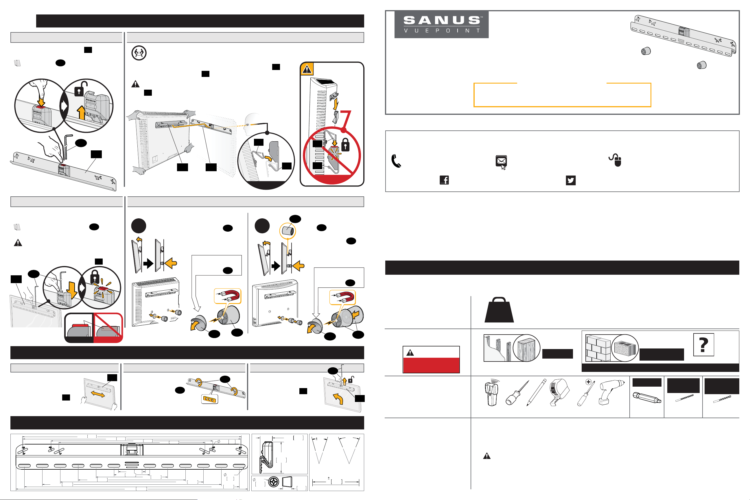
Attach TV to Wall Plate
Unlock the Wall Plate
3.1
Press the button on wall plate 10 to
release the safety latch.
NOTE: “L” pin 16 is provided to
release or engage the safety latch when
your TV is installed.
16
10
3.3
Press down on the safety latch until the
button pops up AND you hear a "click".
engage the safety latch.
Lock the Wall Plate
NOTE: If needed, use “L” pin 16 to
CAUTION: Avoid potential personal
injury or property damage! The safety
latch must be locked, so the TV is
securely fastened to the wall plate 10.
16
10
3.2
Hang Your TV
HEAVY! Use assistance with this step.
Use two people to hang the TV, to visually ensure TV bracket
hung correctly onto wall plate 10 (see side view).
IMPORTANT: DO NOT lower TV straight down onto wall
plate 10 -- this will engage the lock. Safety latch must be released
for proper installation (See STEP 3.1).
01
01 10
Side View
3.4
No Tilt Feature (OPTIONAL
Place magnetic
A B
leveling feet 14 in
the lower corners of
the TV.
For non-metal back
TVs, use adhesivebacked disc
)
.
15
01
is
10
09
01
10
Side View
If you used spacers
09
in STEP 1.2,
stack both magnetic
leveling feet 14
together and place in
the lower center of
the TV.
For non-metal back
TVs, use adhesivebacked disc
15
F
61
Instruction Manual
We’ll Make It Stress-Free
If you have any questions along the way, just give us a call.
1-888-333-9952 We’re ready to help!
Thank you for choosing Sanus VuePoint! Please take a moment to let us know how we did:
Call us: 1-888-333-9952 Email us: info@sanus.com Leave a review: vuepoint.sanus.com
Find us on Facebook: SANUS Follow us on Twitter @sanussystems
Milestone AV Technologies and its a liated corporations and subsidiaries (collectively, “Milestone”), intend to make this manual accurate and complete. However, Milestone makes no claim that the
information contained herein covers all details, conditions, or variations. Nor does it provide for every possible contingency in connection with the installation or use of this product. The information
contained in this document is subject to change without notice or obligation of any kind. Milestone makes no representation of warranty, expressed or implied, regarding the information contained herein.
Milestone assumes no responsibility for accuracy, completeness or su ciency of the information contained in this document.
©2015 Milestone AV Technologies. All rights reserved. Sanus is a division of Milestone.
All other brand names or marks are used for identifi cation purposes and are trademarks of their respective owners.
SANUS • 6436 City West Parkway • Eden Prairie, MN 55344 USA
IMPORTANT SAFETY INSTRUCTIONS
.
Before getting started, let’s make sure this mount is perfect for you!
– SAVE THESE INSTRUCTIONS – PLEASE READ ENTIRE MANUAL PRIOR TO USE
6902-002149 00
Button
Adjustments
Lateral Shift
Slide the TV side to side.
Make sure your TV is
locked to wall plate
(STEP 3.3).
10
Dimensions
19.69 500.0
Side View Side View
10
( in. [mm] )
609.6
11.81
23.62
300.0
24.00
Level
Remove the TV.
Loosen both screws 13,
adjust level, then retighten
the screws (STEP 2.3).
600.0
3.94 100.0
2.95
25.50
647.7
450.0
7.87
200.0
16.00
17.72
75.0
406.4
15.75 400.0
15
23.62
13
0.20
0.34
8.8
600.0
5.1
14
Remove the TV
Disconnect your cables.
1.12
28.6
1.10
27.9
10
LEVELING
Unlock wall plate
(STEP 3.1).
Lift the TV up and away.
2.77
70.3
0.98
25.0
15
16
1.5°
1.5°
3.40
86.4
LATERAL SHIFT
14
10
5°
OPTIONAL
TILT
1
2
3
4
Does your TV
(including accessories)
weigh more than
135 lbs. (61 kg)?
What is your
wall made of?
CAUTION:
DO NOT install
into drywall alone
Do you have all of
the tools needed?
Ready to begin?
135 lbs.
(61 kg)
Please read through these instructions completely to be sure you’re comfortable with this easy install process.
Also check your TV owner’s manual to see if there are any special requirements for mounting your TV.
If you do not understand these instructions or have doubts about the safety of the installation, assembly or use
of this product, contact Customer Service at 1-888-333-9952.
CAUTION: Avoid potential personal injuries and property damage!
● This product includes directions and hardware for use with wood studs – DO NOT install into drywall alone.
● The wall must be capable of supporting fi ve times the weight of the TV and mount combined.
● Do not use this product for any purpose not explicitly specifi ed by manufacturer.
● Manufacturer is not responsible for damage or injury caused by incorrect assembly or use.
No — Perfect!
Yes — This mount is NOT compatible. Visit MountFinder.Sanus.com or call
1-888-333-9952 to fi nd a compatible mount.
Drywall with
wood studs?
Perfect!
Call Customer Service: 1-888-333-9952
ScrewdriverTape MeasureStud Finder Awl Pencil
Electric Drill Square Driver Bit
Solid concrete or
concrete block?
Concrete kit required
[NOT INCLUDED]
INCLUDED
Wood Stud
Applications
1/8 in. (3.2 mm)
Wood
Drill Bit Drill Bit
Unsure?
Concrete
Applications
5/16 in. (8 mm)
Concrete
Page 2
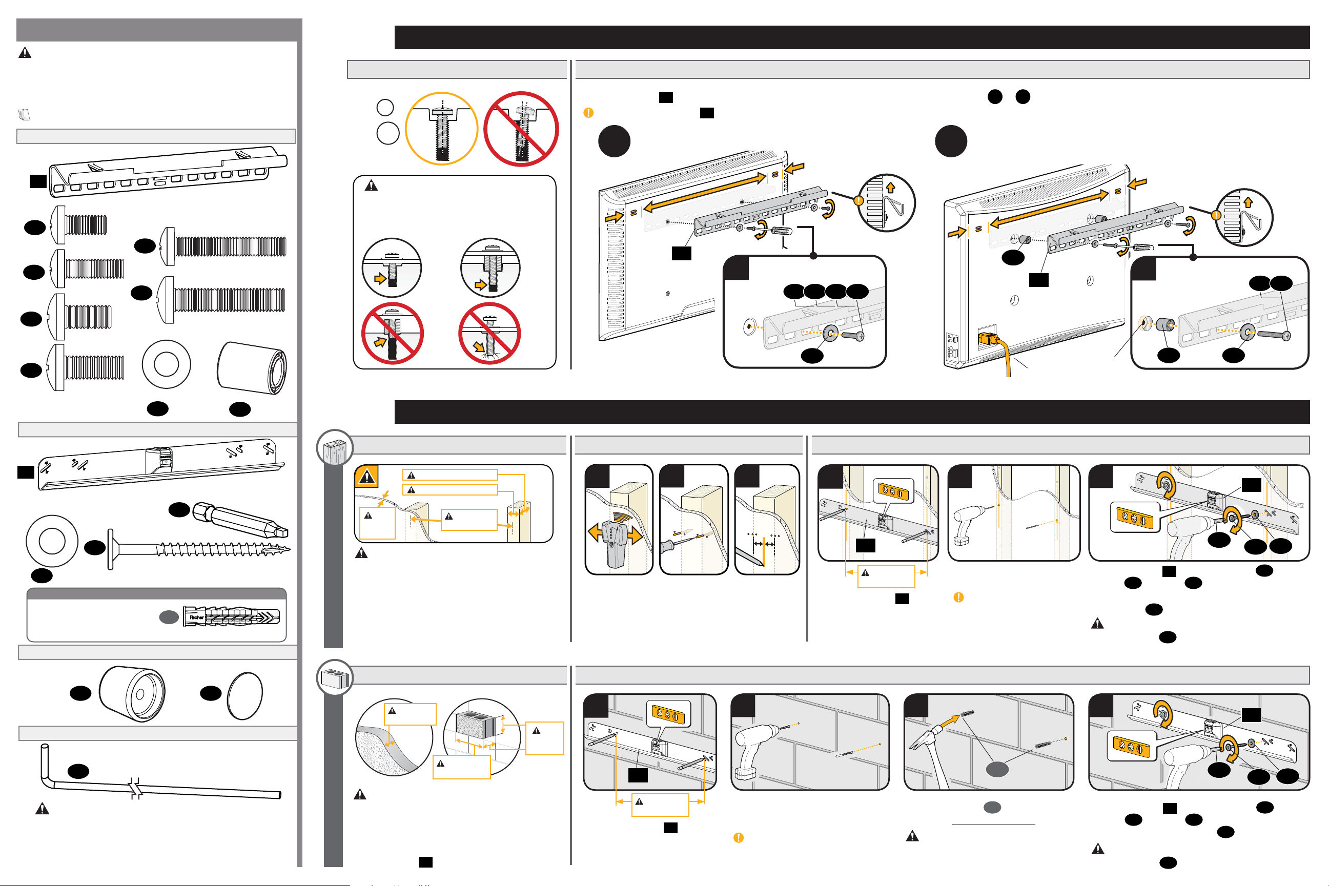
Parts and Hardware
WARNING: This product contains small items that could be a
choking hazard if swallowed. Before starting assembly, verify all parts
are included and undamaged. If any parts are missing or damaged, do
not return the damaged item to your dealer; contact Customer Service.
Never use damaged parts!
NOTE: Not all hardware included will be used.
Parts and Hardware for STEP 1
TV Bracket
01
x1
TV Screws
02
x2
03
x2
04
x2
05
x2
09
Parts and Hardware for STEP 2
Wall Plate
M6 x 12mm
M6 x 20mm
M8 x 16mm
M8 x 20mm
06
x2
07
x2
Washers
08
M6/M8
x2
M6 x 35mm
M8 x 35mm
Spacers
22mm
x2
09
1
Attach TV Bracket to TV
Select Your TV Screws
1.1
M6
M8
CAUTION: Verify thread engagement of the
screw or spacer/screw combination in STEP 1.2.
— Too short will not hold the TV
— Too long will damage the TV
Correct Correct
To o
Short
Attach Wall Plate to Wall
2
2.1A
Verify Your Wall
To o
Long
Attach the TV Bracket
1. 2
Center TV bracket 01 on your TV's hole pattern and securely attach using hardware confi guration A or
IMPORTANT: TV bracket 01 must be oriented on the TV as shown.
A B
• Flat Back TV [AND TV closer to the wall]
Top of TV
• Rounded Back TV
• Extra Space Needed [for cables or inset holes]
01
A
02 03 04 05
08
2.2A
Find the Stud Centers
2.3A
Attach the Wall Plate
B
, depending on your TV needs.
09
01
Inset
Cables
Holes
Top of TV
B
06 07
09 08
10
x1
Washers
Wood Screws (Wall Plate Screws)
13
x2
12
x2
Concrete Anchor Kit (NOT INCLUDED)
For concrete installations:
*
Contact customer service at
1-888-333-9952 to have these
anchors shipped directly to you.
Parts for STEP 3 (OPTIONAL)
Stando
(Magnetic Leveling Feet)
Part for Adjustments
**
14
x2
“L” Pin
16
x1
#10 x 2 1/2 in.
*
Driver Bit (Square)
11
x1
1
C
x2
Fischer UX8x50R Anchor
(Adhesive backed)
Disc
15
x2
Min. 3 1/2 in. (89 mm)
Min. 1 1/2 in. (38 mm)
Max.
5/8 in.
(16 mm)
CAUTION: Avoid potential personal injuries and
property damage!
● Drywall covering the wall must not exceed 5/8 in. (16 mm).
● Minimum wood stud size: common 2 x 4 in. (51 x 102 mm)
nominal 1½ x 3½ in. (38 x 89 mm).
● Minimum horizontal space between fasteners: 16 in. (406 mm).
● Stud centers must be verified – not all walls have
conventional 16 in. (406 mm).
WOOD STUD OPTION 2A
2.1B
Verify Your Wall
Min. 8 in.
(203 mm)
(406 mm)
Min. 16 in.
(406 mm)
Min. 16 in.
Min.
8 in.
(203 mm)
1
Locate the
studs using a
stud fi nder.
2.2B
1
2 3
Probe the wall
with an awl or
drill bit to verify
the stud edges.
Attach the Wall Plate
Mark the
center of
both studs.
2 3 4
10
1
10
Min. 16 in.
(406 mm)
Position wall plate 10 at your
desired height. Level, then
mark the two hole locations.
2
Drill two pilot holes using a
1/8 in. (3.2 mm) drill bit.
IMPORTANT: Pilot holes
must be drilled to a depth of
2.5 in. (63 mm).
C
1
*
3
11
Install wall plate 10 with two washers
screws
Adjust leveling, if needed, then securely tighten
both screws
13
, using bit 11.
13
.
10
13
12
12
and
CAUTION: Improper use could reduce the holding
power of screws 13. DO NOT over-tighten the screws.
10
11
13
12
WARNING: This product contains a magnet. If an implanted
**
medical device such as a pacemaker or implantable cardioverter defi brillator
(ICD) is in use, magnetic fi elds may a ect the operation of those devices,
resulting in serious injury or death. If you have an implanted medical device,
keep at least 13 cm (5 in.) between your device and the magnet. Please consult
with your physician or medical professional prior to using this product.
CAUTION: Avoid potential personal injuries and
property damage!
● Minimum solid concrete thickness: 8 in. (203 mm).
● Minimum concrete block size: 8 x 8 x 16 in. (203 x 203 x 406 mm).
● Minimum horizontal space between fasteners: 16 in. (406 mm).
CONCRETE OPTION 2B
● Mount wall plate
10
directly onto the concrete surface.
Min. 16 in.
(406 mm)
Position wall plate 10 at your
desired height. Level, then
mark the two hole locations.
Drill two pilot holes using a 5/16 in.
(8 mm) masonry drill bit.
IMPORTANT: Pilot holes must be
drilled to a depth of 2.75 in. (70 mm).
Never drill into the mortar between blocks.
Insert two anchors
included in Concrete Anchor Kit *).
C
(Fischer UX8x50R
1
CAUTION: Be sure the anchors are
seated flush with the concrete surface.
10
Install wall plate
screws
Securely tighten both screws 13.
13
, using bit 11.
with two washers
12
and
CAUTION: Improper use could reduce the holding
power of screws 13. DO NOT over-tighten the screws.
 Loading...