

Page 1
SLF
WE’RE HERE TO HELP
226
INSTRUCTION MANUAL
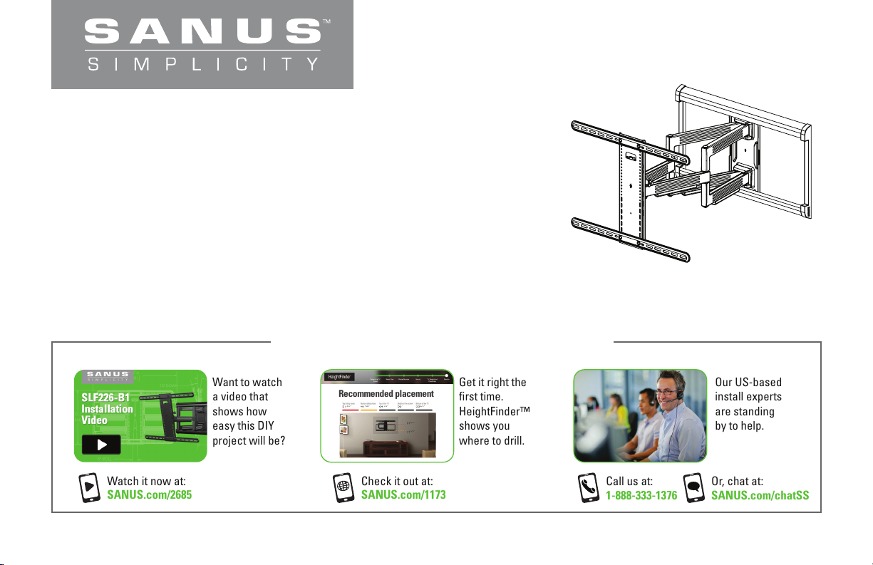
Watch it now at:
SANUS.com/2685
Want to watch
a video that
shows how
easy this DIY
project will be?
Recommended placement
Check it out at:
SANUS.com/1173
Get it right the
first time.
HeightFinder™
shows you
where to drill.
Call us at:
1-888-333-1376
Our US-based
install experts
are standing
by to help.
Or, chat at:
SANUS.com/chatSS
Page 2
IMPORTANT SAFETY INSTRUCTIONS – PLEASE READ MANUAL PRIOR TO USE – SAVE THESE INSTRUCTIONS
Please read through these instructions completely to be sure you’re comfortable with this easy install process.
Check your TV owner’s manual to see if there are any special requirements for mounting your TV.
If you do not understand these instructions or have doubts about the safety of the installation, assembly or use of this product, contact Customer Service.
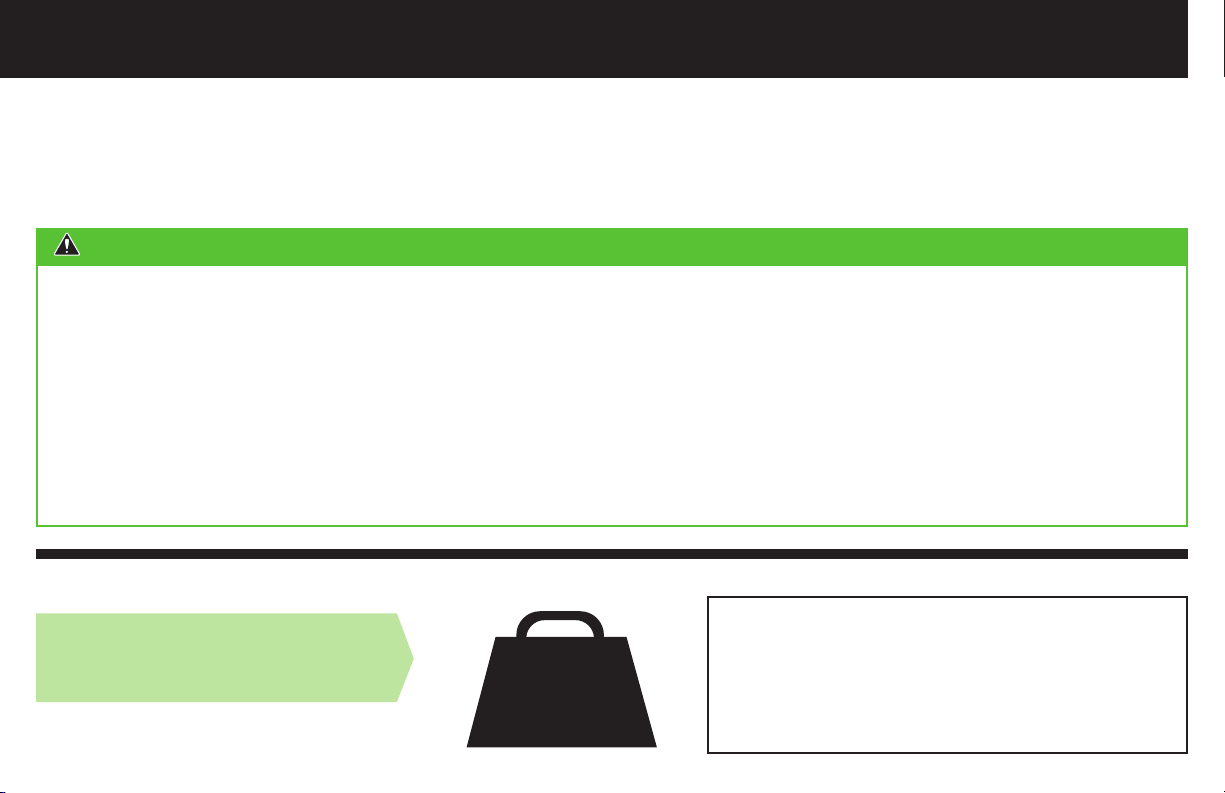
CAUTION: Avoid potential personal injuries and property damage!
● This product is designed ONLY to be installed into wood studs, solid concrete or concrete block.
— DO NOT INSTALL INTO DRYWALL ALONE — DRYWALL ALONE WILL NOT HOLD THE WEIGHT OF YOUR TV.
● This product is designed for INDOOR USE ONLY.
● The wall must be capable of supporting five times the weight of the TV and mount combined.
● Do not use this product for any purpose not explicitly specified by manufacturer.
● Manufacturer is not responsible for damage or injury caused by incorrect assembly or use.
TV Weight Limit
(including accessories)
DO NOT EXCEED
2
135 lbs.
(61.2 kg)
If your TV (plus accessories) weighs MORE,
this mount is NOT compatible.
Visit Simplicity.SANUS.com or call customer
service to find a compatible mount.
Page 3
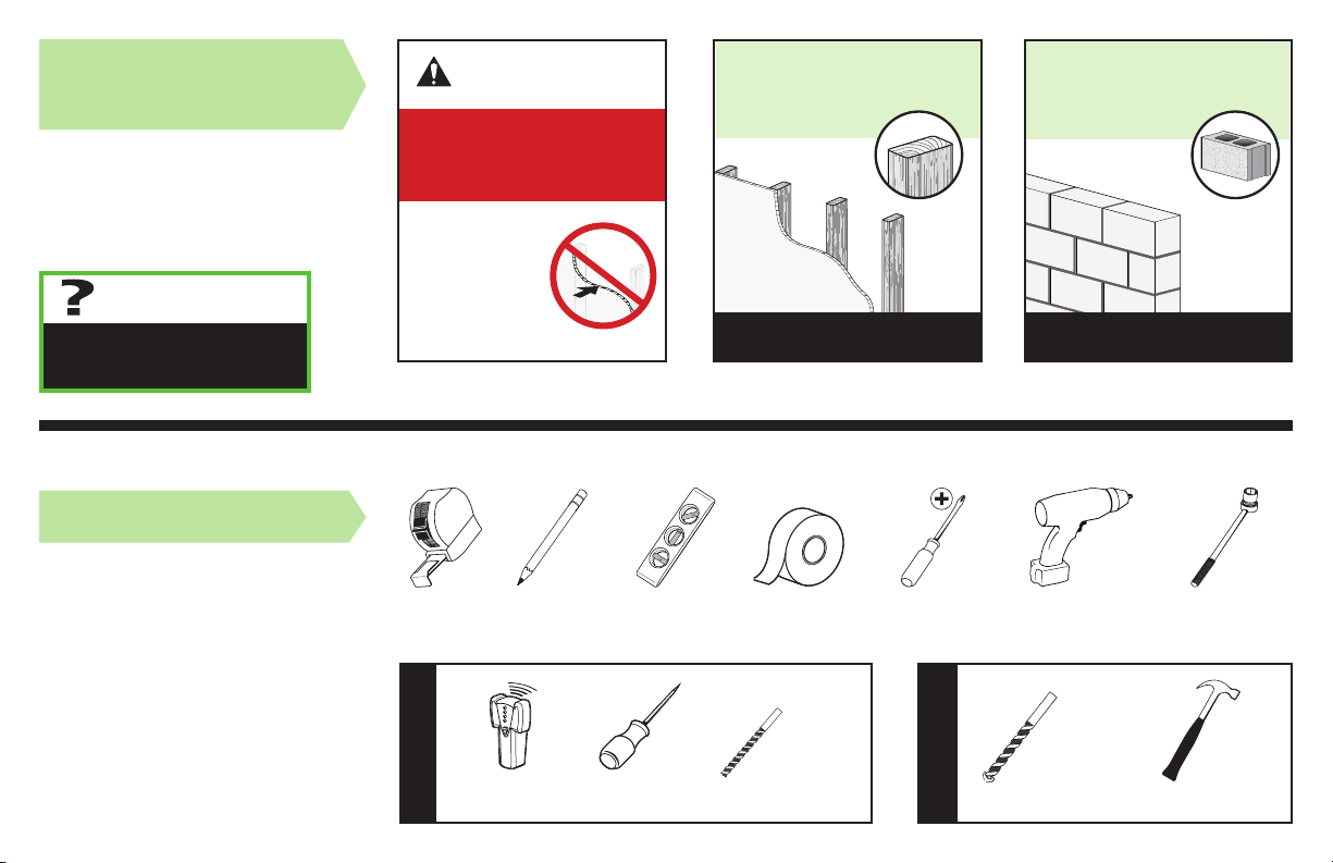
Wall
Construction
ONLY install on
these acceptable
wall types.
Unsure
Call Customer Service
888-333-1376
Tools Needed
CAUTION:
DO NOT install
in drywall alone
Drywall alone
will NOT hold
the weight of
your TV.
wood studs Solid concrete or
concrete block
ACCEPTABLE ACCEPTABLE
1/2 in.
(13 mm)
Measure
Wood Stud Install
Pencil Level Tape
Stud
Finder
Awl
7/32 in.
(5.5 mm)
Wood
Drill Bit
ScrewdriverTape
(10 mm)
Concrete
Concrete Install
Drill Bit
Electric
Drill
3/8 in.
Socket
Wrench
Hammer
3
Page 4

Dimensions
TV INTERFACE
23.6
600
3.9
100
WALL PLATE
23.6
600
15.2
387
25.8
655
FULLY ASSEMBLED MOUNT
27.6
701
17.7
450
5° ROLL
4
24.0
610
16.0
406
27.6
701
in.
3-D
[mm]
15.7
3.9
400
100
0.33
8.4
17.7
450
11.5
293
TOP VIEW - EXTENDED
40° - 85°
TOP VIEW - RETRACTED
2.7
67
SIDE VIEW - EXTENDED
15° DOWN
4° UP
26
658
SIDE VIEW - RETRACTED
15.1
384
Page 5
Supplied Parts and Hardware
M8 x 25mm
M8 x 50mm
M8 x 45mm
M8 x 35mm
M8 x 16mm
M8 x 20mm
2.5mm
22mm
M6 x 20mmM6 x 12mm
M4 x 12mm
M6 x 35mm
M4 x 35mm
M5 x 10mm
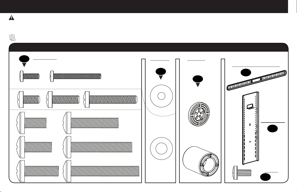
WARNING: This product contains small items that could be a choking hazard if swallowed.
Before starting assembly, verify all parts are included and undamaged. If any parts are missing or damaged, do not return the damaged item to
your dealer; contact Customer Service. Never use damaged parts!
NOTE: Not all hardware included will be used.
STEP 1 Parts and Hardware
M4
M6
M8
TV Screws
01
(qty. 4 each) [Only one size fits your TV]
Washers
(qty. 4 each)
02
M4
M6/M8
Spacers
(qty. 4 each)
[If necessary]
03
M4/M6/M8
M4/M6/M8
Horizontal TV Bracket
(qty. 2)
04
Vertical
TV Bracket
05
(qty. 1)
TV Bracket
Screw
06
(qty. 4)
5
Page 6
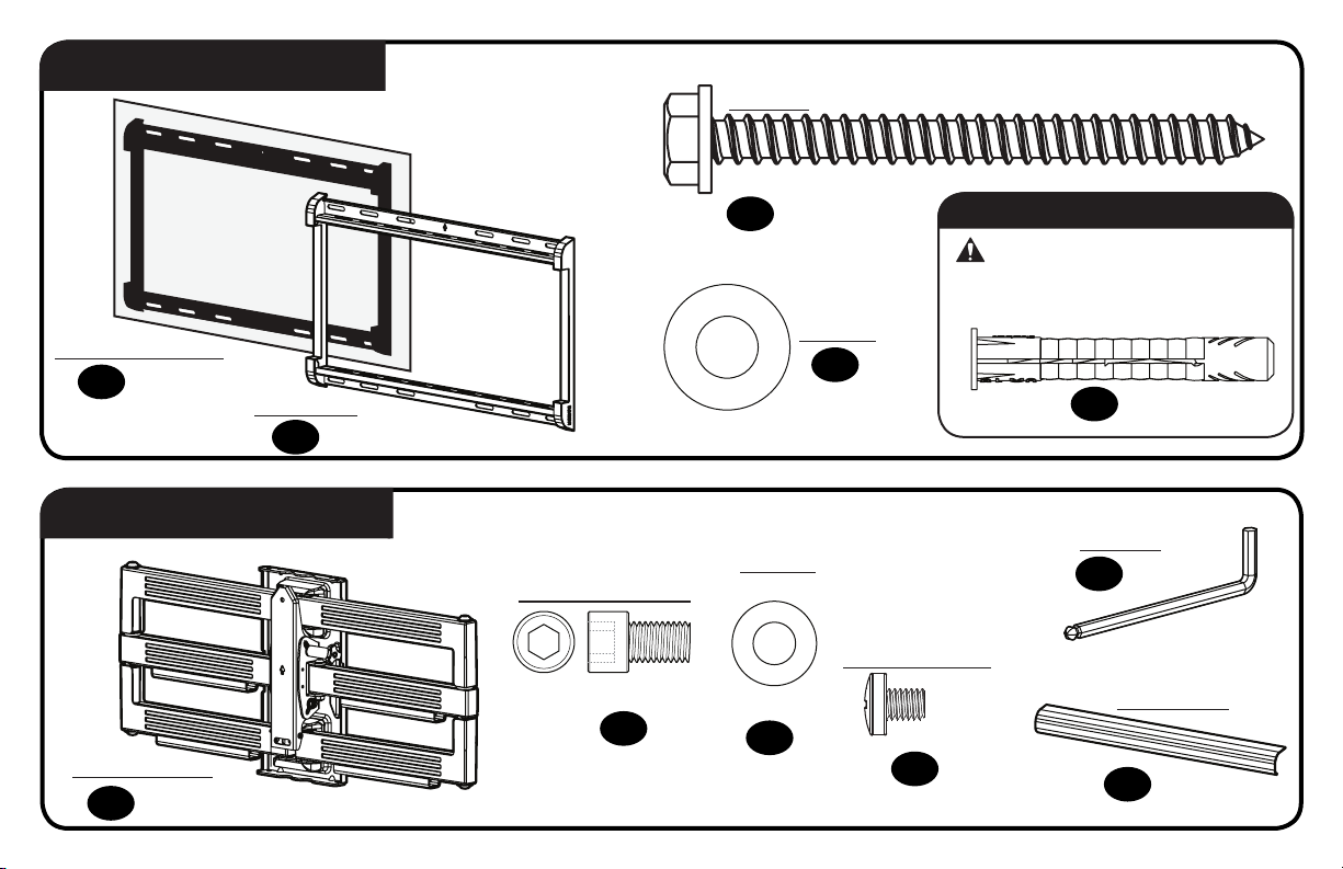
STEP 2 Parts and Hardware
Lag Bolt
5/16 in. x 3 ½ in.
(qty. 5)
09
For concrete installations ONLY
CAUTION:
Do not use in drywall or wood
Drilling Template
(qty. 1)
07
STEP 3 Parts and Hardware
Arm Assembly
(qty. 1)
12
6
Wall Plate
(qty. 1)
08
Wall Plate Screw
1/4-20 x 3/8 in.
13
(qty. 4)
5/16 in.
Washer
(Wall Plate Screw)
1/4 in.
14
(qty. 4)
Washer
10
(qty. 5)
Locking Screw
M5 x 6mm
15
(qty. 1)
Concrete Anchor
(qty. 5)
11
Hex Key
(qty. 1)
16
Cover Plate
(qty. 2)
17
3/16 in.
Page 7
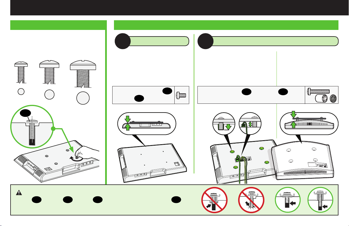
STEP 1 Attach Brackets to TV
1.2 Select TV Screw Length and Spacers1.1 Select TV Screw Diameter
Only one screw size fits your TV.
M4
M6
01
M8
Use short TV screws
Spacers
NO SPACER SPACER NEEDED
A B
• Flat Back TV
[TV brackets
lay flat on your TV]
01
not needed.
03
CAUTION: Verify adequate thread engagement with your
screw 01, washer 02, spacer 03 combination AND TV bracket 04.
— Too short will not hold your TV. — Too long will damage your TV.
• Flat Back TV with
Extra Space Needed
[for deep inset holes
or cable interference]
.
Use long TV screws 01 and spacers
create extra space between the TV and TV bracket.
Inset Holes Cables Rounded Back
Too Short
Too Long
• Rounded or
Irregular Back TV
[TV brackets NOT
resting flat on your TV]
03
to
Correct
7
Page 8
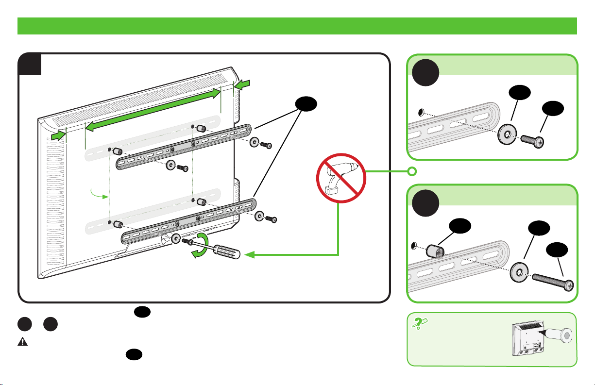
1.3 Attach TV Brackets to Your TV
1
04
TV HOLE
PATTERN
TYPICAL INSTALLATION ILLUSTRATED.
Center Horizontal TV brackets 04 over your TV's hole pattern and attach using screw combination
or
A
CAUTION: Avoid potential personal injuries and property damage! DO NOT use power tools for
this step. Tighten the screws
8
you selected for your TV.
B
only enough to secure the TV brackets to the TV.
01
A
NO SPACER
B
SPACER NEEDED
03
If your TV included
inset spacers or wall
mount adapters, see
Troubleshooting (PAGE 21).
02
01
02
01
Page 9
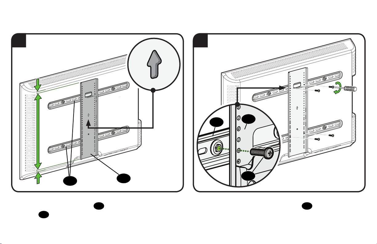
2 3
04
Position the vertical TV bracket 05 over the horizontal TV
brackets 04 and center with your TV.
05
04
05
06
Secure the assembly with the four screws 06.
9
Page 10

STEP 2A Attach Wall Plate Wood Stud Installation
CAUTION: Avoid potential personal injury or property damage!
● Drywall covering the wall must not exceed 5/8 in. (16 mm)
● Minimum wood stud size: nominal 2 x 4 in. (51 x 102 mm) actual 1 ½ x 3 ½ in. (38 x 89 mm)
● Minimum horizontal space between fasteners: 16 in. (406 mm)
● Stud centers must be verified
1
Locate studs. Verify the center of the stud(s) using an awl, a thin nail,
or an edge to edge stud finder.
10
MAX 5/8 in. (16 mm)
MIN.
16 in.
(406 mm)
2
07
Level the drilling template 07 and align the hole pattern over the
center of your studs, then tape in place.
Page 11

3 4
3 ½ in. (89 mm)
7/32 in.
07
(5.5 mm)
10
09
08
Drill pilot holes then remove the drilling template 07.
IMPORTANT: Be sure to drill into the center of the stud.
IMPORTANT: Pilot holes must be drilled to a depth of 3 ½ in. (89 mm),
using a 7/32 in. (5.5 mm) diameter drill bit.
Install the wall plate 08 using four lag bolts 09 and washers 10.
Tighten all lag bolts only until they are pulled firmly against the wall plate.
CAUTION: Improper use could reduce the holding power of the
lag bolt. DO NOT over-tighten the lag bolts.
Go to STEP 3 on PAGE 14.
11
Page 12

STEP 2B Attach Wall Plate
Solid Concrete or Concrete Block Installation
CAUTION: Avoid potential personal injury or property damage!
● Mount wall plate 08 directly onto concrete surface (no wall covering)
● Minimum solid concrete thickness: 8 in. (203 mm)
● Minimum concrete block size: 8 x 8 x 16 in. (203 x 203 x 406 mm)
● Minimum horizontal space between fasteners: TOP RAIL = 8 in. (203 mm), BOTTOM RAIL = 16 in. (406 mm)
● For concrete applications, arm
12
(STEP 3) must remain centered in wall plate 08. Keep this in mind when selecting wall plate location
1 2
07
MIN.
16 in.
(406 mm)
Level the drilling template 07 and tape in place.
12
07
3 ¾ in. (95 mm)
3/8 in.
(10 mm)
Drill FIVE pilot holes into solid concrete as shown (three on top).
CAUTION: Never drill into the mortar between blocks.
IMPORTANT: Pilot holes must be drilled to a depth of 3 ¾ in. (95 mm),
using a 3/8 in. (10 mm) diameter drill bit.
Page 13

3
4
10
09
08
11
Remove drilling template 07 and insert five concrete anchors 11.
CAUTION: Be sure the anchors are seated flush with the
concrete surface.
Install the wall plate 08 using five lag bolts 09 and washers 10.
Tighten all lag bolts only until they are pulled firmly against the wall plate.
CAUTION: Improper use could reduce the holding power of the
lag bolt. DO NOT over-tighten the lag bolts.
13
Page 14

STEP 3 Attach TV to Wall Plate
3.1 Attach Arm Assembly to Wall Plate
1
12
08
Position the arm assembly 12 on the wall plate
into the wall plate channel, then rotating the bottom toward the wall.
14
08
by tilting the top
2
16
08
12
Secure with four wall plate screws 13 and washers
hex key 16.
14
13
using
14
Page 15

3.2 Attach TV to Arm Assembly
HEAVY! You may need assistance with this step.
1
12
05 05
05
12
Hang your TV onto the arm assembly 12 by first hooking the top
support of vertical TV bracket 05, then resting the TV into place.
2
12
15
Lock your TV to the arm assembly 12 with locking screw 15.
CAUTION: Avoid potential personal injury or property damage!
This locking screw 15 must be installed to secure the TV onto the
arm assembly
12
.
15
Page 16

3.3 Install Cover Plates
Store hex key 16 in wall plate 08, for future use.
NOTE: Before installing the cover plates, use the hex key 16 to make any necessary adjustments as shown on pages 18 - 20.
Bow the middle of each cover plate 17 to slip the ends into the channels of the wall plate 08.
16
17
08
16
17
08
17
16
Page 17

Manage Cables
1. Remove the four cable covers C.
NOTE: fully extend arms
2. Route your cables through the arms 12 shown — to avoid pinching.
3. Reattach the cable covers C over the cables.
12
to ensure enough slack in cables.
C
1
C
2
3
C
17
Page 18

TV Adjustments
TILT ADJUSTMENT
Your TV should adjust easily when moved, then stay in place.
If your TV is too loose or too tight, adjust the side tension knob
by hand or use hex key 16.
NOTE: Once your TV is in place, tighten the tension knob
prevent unwanted movement.
Tighten
Loosen
T
LEVEL ADJUSTMENT
Adjust the leveling of your TV by turning the level screw L.
T
to
T
L
18
Page 19

LATERAL SHIFT
13
14
17
2a
08
1b
3
12
1a
1. Disconnect cables and remove your TV (PAGE 20).
2. Remove the cover plates 17 and the four screws 13 /washers
14
from wall plate 08.
3. Reposition the arm assembly 12 on the wall plate (STEP 3.1).
2b
13
14
08
17
4b
5a
12
5b
4. Reattach the four screws 13 /washers 14 (STEP 3.1) and
replace the cover plates 17 (STEP 3.3).
5. Hang your TV onto the arm assembly 12 following STEP 3.2.
4a
19
Page 20

REMOVING THE TV
HEAVY! You may need assistance with this step.
3
12
2
1. Disconnect cables.
2. Remove screw 15.
3. Lift TV up and off the arm assembly 12.
20
1
15
Page 21

Troubleshooting
TV Supplied Spacers
TV SUPPLIED SPACERS
Use your TV supplied spacer for:
A B
• Flat Back TV [TV brackets lay flat on your TV]
NOTE:
M8 screws can be used without the washer for extra thread engagement.
FLAT BACK
a
• Flat Back TV with Extra Space Needed
ROUND BACK CABLES
If you are uncertain about your hardware selection,
contact Customer Service at 1-888-333-1376.
Use your TV supplied spacer and spacer 03 for:
• Rounded or Irregular Back TV
[for deep inset holes or cable interference]
NOTE:
M8 screws can be used without the washer for extra thread engagement.
[TV bracket s NOT resting flat on your TV]
b
TV Supplied
Spacer
CAUTION: Avoid potential injury or property damage!
Use the correct screw length for adequate thread engagment.
Correct
– Too short will
not hold the TV.
– Too long will
damage the TV.
Too Short
Too Long
TV Supplied
Spacer
03
CAUTION: Avoid potential injury or property damage!
Use the correct screw length for adequate thread engagment.
Correct
– Too short will
not hold the TV.
– Too long will
damage the TV.
Too Short
Too Long
21
Page 22

ESPAÑOL
Lea atentamente estas instrucciones en su totalidad para asegurarse de que está familiarizado con el sencillo proceso de instalación.
Consulte igualmente el manual de su televisor para conocer si existen requisitos especiales para el montaje de su aparato.
Si no entiende las instrucciones o si tiene dudas acerca de la seguridad de la instalación, el montaje o el uso del producto, póngase en contacto
con el Servicio de Atención al Cliente o llame a nuestro servicio técnico al número 1-888-333-1376 .
- LEA TODO ESTE MANUAL ANTES DE UTILIZAR ESTE PRODUCTO - GUARDE ESTAS INSTRUCCIONES
INSTRUCCIONES IMPORTANTES DE SEGURIDAD
PRECAUCIÓN: Evite posibles lesiones personales y daños materiales.
● Este producto se ha diseñado para su uso en montantes de madera, hormigón macizo y paredes de bloques de hormigón:
NO lo instale en paredes únicamente de yeso
● La pared debe ser capaz de soportar hasta cinco veces el peso combinado del televisor y la montura
● No utilice este producto para ningún otro propósito que no sea el explícitamente especificado por el fabricante
● El fabricante no se responsabiliza de ningún daño o lesión resultante del montaje incorrecto o el uso indebido
Peso máximo
(incluidos los accesorios)
NO EXCEDAS
La construcción
de su pared
SOLAMENTE instalar
en estos tipos
aceptables de la pared.
¿No está seguro?
Llame al Servicio de Atención al Cliente
22
61,2 kg
(135 lbs.)
PRECAUCIÓN:
NO
instalar en
panel de
yeso solo
Instalación en panels de
yeso solo NO soportará
el peso de su TV.
Si su TV (incluidos los accesorios) pesa MÁS, esta montura
NO es compatible.
Visite vuepoint.sanus.com o llame al número 1-888-333-1376
para encontrar una montura compatible.
Montantes de madera Hormigón macizo o
bloque de hormigón
ACEPTABLE ACEPTABLE
Page 23

herramientas
necesarias
métrica
Lápiz Nivel Cinta
Adhesiva
13 mm
(1/2 in.)
DestornilladorCinta
Taladro
eléctrico
Llave de
vaso
Montantes
de Madera
Dimensiones
Piezas y accesorios suministrados
Localizador
de
montantes
Punzón
5,5 mm
(7/32'')
Madera
Broca
Montantes
de Cemento
10 mm
(3/8'')
Hormigón
Broca
VER PÁGINA 4
VER PÁGINAS 5-6
Martillo
ADVERTENCIA: Este producto contiene piezas pequeñas que, si fuesen tragadas, podrían producir asfixia.
Antes de iniciar el ensamblaje, compruebe que todas las piezas estén incluidas y en buenas condiciones. Si faltan piezas o alguna está dañada,
no devuelva el artículo al distribuidor; póngase en contacto con el servicio de atención al cliente. Nunca utilice piezas deterioradas.
NOTA: No todos los accesorios incluidos deberán utilizarse.
SOLO para instalaciones en hormigón
PRECAUCIÓN: No se debe utilizar en paredes de yeso ni de madera
PASO 1 Colocar las placas de sujeción en el televisor
11
x5
UX10 x 60R
VER PÁGINA 7
1,1 Seleccione el diámetro de los tornillos para el televisor VER PÁGINA 7
Solo un tamaño de tornillo es compatible con su TV.
23
Page 24

ESPAÑOL
1,2 Seleccione la longitud de los tornillos para el televisor VER PÁGINA 7
SIN ESPACIADOR CON ESPACIADOR
A B
• Televisor con dorso plano
[Los soportes del televisor
manera plana en él]
Use los tornillos del televisor cortos 01.
No hacen falta espaciadores
04
se apoyan de
03
.
PRECAUCIÓN: Verifique que el tornillo o la combinación de tornillo
televisor 04 enrosquen correctamente. Si el tornillo es demasiado corto no sostendrá el televisor. Si es demasiado largo dañará el televisor.
• Televisor con dorso plano
con necesidad de espacio adicional
[para orificios empotrados o interferencia de cables]
Use los tornillos del televisor largos
espacio adicional entre el televisor y el soporte.
01
arandelas 02, espaciador 03 y placas de sujeción del
,
01
y los espaciadores
• Televisores con dorso plano o irregular
[Los soportes del televisor
manera plana en él]
03
para crear
04
NO se apoyan de
1,3 Arme las placas de sujeción del televisor VER PÁGINA 8
Para televisores que incluyen separadores insertados o aros adaptadores para soportes murales, see Solución de problemas en página 21.
A
1. Centre los soportes horizontales del televisor
eligió para su televisor.
PRECAUCIÓN: Evite posibles lesiones personales y daños materiales. NO use herramientas eléctricas en este paso. Apriete los
tornillos
2. Coloque el soporte vertical del televisor
3. Fije el conjunto con los cuatro tornillos
24
01
con la fuerza adecuada para fijar el soporte del televisor al aparato.
04
sobre el patrón de orificios del aparato y fíjelos combinando los tornillos
05
sobre los soportes horizontales
06
.
04
y céntrelo con el aparato.
B
o
que
Page 25

ESPAÑOL
PASO 2A Fijar la placa mural
PRECAUCIÓN: Evite lesiones personales y daños materiales.
● El yeso que recubre la pared no debe exceder los 16 mm (5/8'')
● Tamaño mínimo del montante de madera: común 51 mm x 102 mm (2'' x 4'') nominal 38 mm x 89 mm (1 ½'' x 3 ½'')
● Espacio horizontal mínimo entre los elementos de sujeción: 406 mm (16'')
1. Localice los montantes. Verifique el centro de los montantes con un punzón o un clavo delgado, o bien utilice un detector de bordes de montantes.
2. Nivele la plantilla de placa mural 07 y fíjela con cinta adhesiva en el lugar.
3. Realice los orificios guía y retire la plantilla de placa mural 07.
IMPORTANTE: Asegúrese de perforar el centro del montante.
IMPORTANTE: Los orificios deben realizarse con una mecha de 5,5 mm (7/32'') de diámetro hasta una profundidad de 89 mm (3 ½'').
4. Instale la placa mural 08 usando cuatro tornillos tirafondo 09 y arandelas 10. Ajuste los tornillos tirafondo solamente hasta que queden
firmes contra la placa mural.
para montantes de madera
VER PÁGINA 10
PRECAUCIÓN: El uso indebido podría reducir la capacidad de retención de los tornillos tirafondo. NO ajuste en exceso los tornillos tirafondo.
PASO 2B Fijar la placa mural
para hormigón sólido o bloques de cemento
VER PÁGINA 12
PRECAUCIÓN: Evite lesiones personales y daños materiales.
● Instale la placa mural
● Espesor mínimo del hormigón: 203 mm (8'')
● Tamaño mínimo del bloque de cemento: 203 x 203 x 406 mm (8'' x 8'' x 16'')
● Espacio horizontal mínimo entre los elementos de sujeción: RIELES SUPERIOR= 203 mm (8''), RIELES INFERIOR= 406 mm (16'')
● Para aplicaciones sobre hormigón, el brazo
hora de seleccionar la ubicación de la placa de pared
08
directamente sobre la superficie de hormigón
12
(PASO 3) debe permanecer centrado en la placa de pared
08
. Téngalo en cuenta a la
1. Nivele la plantilla de placa mural 07 y fíjela con cinta adhesiva en el lugar.
2. Realice los CINCO orificios guía en el hormigón sólido. Nunca perfore el cemento que une los bloques.
IMPORTANTE: Los orificios guía deben realizarse con una mecha de 10 mm (3/8'') de diámetro hasta una profundidad de 95 mm (3¾'').
25
Page 26

ESPAÑOL
3. Retire la plantilla de placa mural 07 e introduzca los anclajes para cemento 11.
PRECAUCIÓN: Cerciórese de que los anclajes queden nivelados respecto de la superficie de hormigón.
4. Instale la placa mural 08 usando cinco tornillos tirafondo 09 y arandelas 10. Ajuste los tornillos tirafondo solamente hasta que queden
firmes contra la placa mural.
PRECAUCIÓN: El uso indebido podría reducir la capacidad de retención de los tornillos tirafondo. NO ajuste en exceso los tornillos tirafondo.
PASO 3 Fije el televisor a la placa mural
3,1 Fijar el módulo del brazo a la placa mural
1. Ubique el módulo del brazo 12 sobre la placa mural
la parte inferior hacia la pared.
2. Fije usando los cuatro tornillos 13 y arandelas
3,2 Acoplar el televisor al módulo del brazo
¡ELEMENTO PESADO! Es posible que necesite ayuda en este paso.
1. Para colgar el televisor del módulo del brazo 12, enganche el soporte superior y luego apoye el televisor en su lugar.
2. Fije el televisor al brazo 12 con un tornillo
15
PRECAUCIÓN: Evite el riesgo de lesiones y daños materiales. Este tornillo
3,3 Instalar las tapas
Guarde la llave hexagonale 16 en la placa mural 08, para su uso en el futuro.
NOTA: Antes de instalar las tapas, use las llaves hexagonales para realizar cualquier ajuste necesario, como se muestra en las páginas 18-20.
Arquee la parte media de cada tapa 17 para introducir los extremos en los canales de la placa mural 08.
26
08
inclinando la parte superior dentro del canal de la placa mural, y rotando luego
14
con la llave hexagonal 16.
.
15
debe instalarse para fijar el televisor al ensamblaje del brazo
VER PÁGINA 14
VER PÁGINA 14
VER PÁGINA 15
VER PÁGINA 16
12
.
Page 27

Organizar los cables
1. Retire la cubierta de los cables C. NOTA: Extienda el brazo 12 por completo antes de pasar los cables.
2. Pase los cables por el brazo
12
3. Vuelva a colocar la cubierta de los cables C por sobre los cables.
.
VER PÁGINA 17
ESPAÑOL
Ajustes del televisor
AJUSTE DE LA INCLINACIÓN
El televisor debe acomodarse fácilmente al moverlo, y luego quedar en su lugar. Si el televisor está demasiado suelto o demasiado ajustado, ajuste la
perilla de tensión lateral T manualmente o con la llave hexagonal 16.
NOTA: Una vez que el televisor esté en su lugar, ajuste las perillas de tensión T para evitar un movimiento indeseado.
AJUSTE DEL NIVEL
Ajuste el nivel de su televisor girando el tornillo L de ajuste de nivel con la ayuda de la llave hexagonal 16.
DESPLAZAMIENTO LATERAL DEL TELEVISOR
1: Retire el televisor (PÁGINA 20). 2: Retire las tapas 17 y los cuatro tornillos 13 de la placa mural 08. 3: Vuelva a ubicar el módulo del brazo
sobre la placa mural (PASO 3,1). 4: Vuelva a colocar los cuatro tornillos (PASO 3,1) y las tapas (PASO 3,3). 5: Cuelgue el televisor del módulo del
brazo siguiendo las instrucciones del PASO 3,2.
EXTRACCIÓN DEL TELEVISOR
1. Desconecte todos los cables. 2. Retire el tornillo 15. 3. Levante el televisor y retírelo del módulo del brazo 12.
Solución de problemas
ESPACIADORES SUMINISTRADOS CON EL TELEVISOR
A
• Televisor con dorso plano [Los soportes del televisor
• Televisor con dorso plano con necesidad de espacio adicional [para orificios empotrados o interferencia de cables]
B
04
se apoyan de manera plana en él]
• Televisores con dorso plano o irregular [Los soportes del televisor
NOTA:
Los tornillos M8 se pueden utilizar sin las arandelas para lograr un mayor enrosque del tornillo.
PRECAUCIÓN: Evite posibles lesiones personales y daños materiales.
— Si es demasiado corto, no sujetará el televisor. — Si es demasiado largo, dañará el televisor.
Use la longitud de tornillo adecuada para la rosca correspondiente.
Si no está seguro acerca de cuáles son las herramientas que debe utilizar,
póngase en contacto con el Servicio de Atención al Cliente al 1-888-333-1376.
04
NO se apoyan de manera plana en él]
VER PÁGINA 18
VER PÁGINA 18
VER PÁGINA 18
VER PÁGINA 19
VER PÁGINA 20
VER PÁGINA 21
27
Page 28

Thank you for choosing SANUS Simplicity! Please take a moment to let us know how we did:
Call us: 1-888-333-1376 Email us: info@sanus.com Leave a review: simplicity.SANUS.com
SANUS SIMPLICITY LIMITED WARRANTY
What the Warranty Covers:
SANUS warrants its products to be free of defects in material and workmanship for the product's Warranty Period. The Warranty Period starts on the original purchase date of the product.
What the Period of Coverage Is:
This Limited Warranty extends only to the original purchaser of the product and not to any subsequent owner. If still owned by the original purchaser, all SANUS Simplicity products are covered
by a limited product warranty for five (5) years from the original purchase date of the product.
How to Get Warranty Service and What We Will Do:
For warranty claims made during the Warranty Period, SANUS will replace any defective product part free of charge. If a part of your SANUS Simplicity product fails, call SANUS at 1-888-333-1376
to make a warranty claim. We will discuss the problem with you and once we confirm the product is under warranty, we will ship replacement parts at no cost to you within 72 hours. This Limited
Warranty does not cover the costs of removing and replacing defective parts from your SANUS Simplicity product. So, if your problem requires a repair technician, you must pay any labor charges.
Additional Limits on the Warranty:
The Limited Warranty is automatically void if your SANUS Simplicity product is modified in any way, improperly installed, taxed beyond its stated weight capacity or otherwise misused or abused. All SANUS
products are intended for indoor use only and any outdoor use voids this Limited Warranty. The Limited Warranty for wall and ceiling mounts is void if the mount is moved from its initial installation.
How State Laws Relate to the Warranty:
To the maximum extent permitted by applicable law, SANUS disclaims any other warranties, express or implied, including warranties of fitness for a particular purpose and warranties of
merchantability. In any event, no express or implied warranty can last longer than the term stated above (“What The Period of Coverage Is”). Some states do not allow disclaimers of implied
warranties or limitations on how long an implied warranty lasts, so these limitations may not apply to you.
SANUS will not be liable for any damages whatsoever arising out of the use or inability to use its products, even if SANUS has been advised of the possibility of such damages. To the maximum extent
permitted by applicable law, SANUS disclaims any responsibility for incidental or consequential damages (such as the cost of repairing or replacing other property which damaged when the device
does not work properly). Some states do not allow the exclusion or limitation of incidental or consequential damages, so the above limitation or exclusion may not apply to you.
Milestone AV Technologies and its aliated corporations and subsidiaries (collectively, “Milestone”), intend to make this manual accurate and complete. However, Milestone makes no
claim that the information contained herein covers all details, conditions, or variations. Nor does it provide for every possible contingency in connection with the installation or use of this
product. The information contained in this document is subject to change without notice or obligation of any kind. Milestone makes no representation of warranty, expressed or implied,
regarding the information contained herein. Milestone assumes no responsibility for accuracy, completeness or suciency of the information contained in this document.
©2018 Milestone AV Technologies. All rights reserved. SANUS is a division of Milestone.
All other brand names or marks are used for identification purposes and are trademarks of their respective owners.
Milestone Global Headquarters • 6436 City West Parkway • Eden Prairie, MN 55344 USA
6903-302010 00
 Loading...