

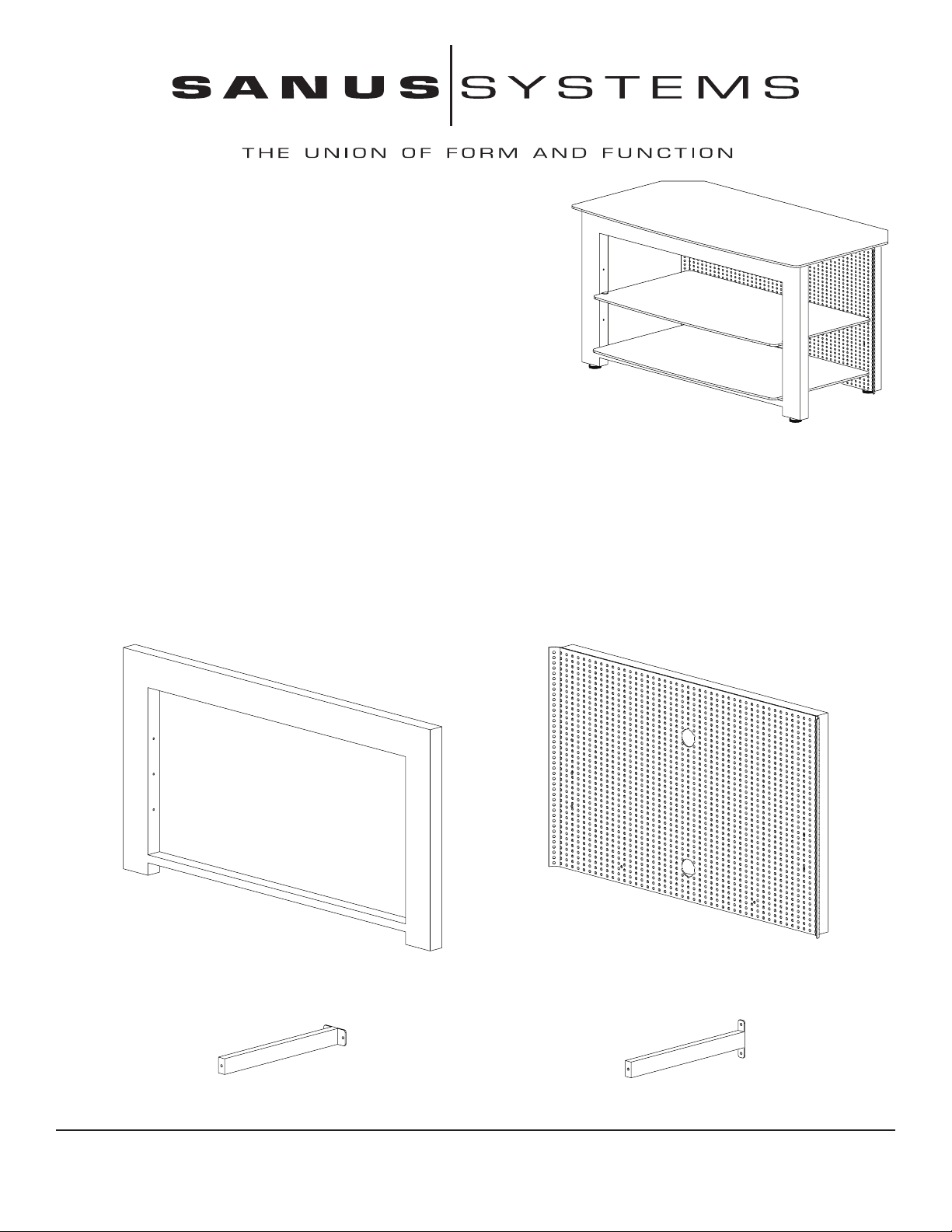
Assembly Instructions for Model: SFV41
Thank you for choosing the Steel Furniture line from Sanus Systems. If you
do not understand these directions, or have any doubts about the safety
of the installation, please call a qualied contractor or contact Sanus at
800.359.5520 or www.sanus.com. Our customer service representatives
can quickly assist you with installation questions and missing or damaged
parts. Replacement parts for products purchased through authorized
dealers will be shipped directly to you. Check carefully to make sure that
there are no missing or defective parts. Sanus Systems can not be liable
for damage or injury caused by incorrect mounting, incorrect assembly,
or incorrect use. Please call Sanus Systems before returning products to
the point of purchase.
CSAV, Inc. and its afliated corporations and subsidiaries (collectively, “CSAV”), intend to make this manual accurate and
complete. However, CSAV makes no claim that the information contained herein covers all details, conditions, or variations.
Nor does it provide for every possible contingency in connection with the installation or use of this product. The information
contained in this document is subject to change without notice or obligation of any kind. CSAV makes no representation of
warranty, expressed or implied, regarding the information contained herein. CSAV assumes no responsibility for accuracy,
completeness or sufciency of the information contained in this document.
Required Tools: Phillips screwdriver
Supplied Parts and Hardware: (Threaded fasteners are shown actual size.)
Front Frame - A
Qty. 1
Upper Brace Bar- C
Qty. 1
Sanus Systems 2221 Hwy 36 West, Saint Paul, MN 55113 06.05.06 (6901-100075)
Customer Service: 800.359.5520. See complementary Sanus products at www.sanus.com
Back Frame - B
Qty. 1
Lower Brace Bar - D
Qty. 2
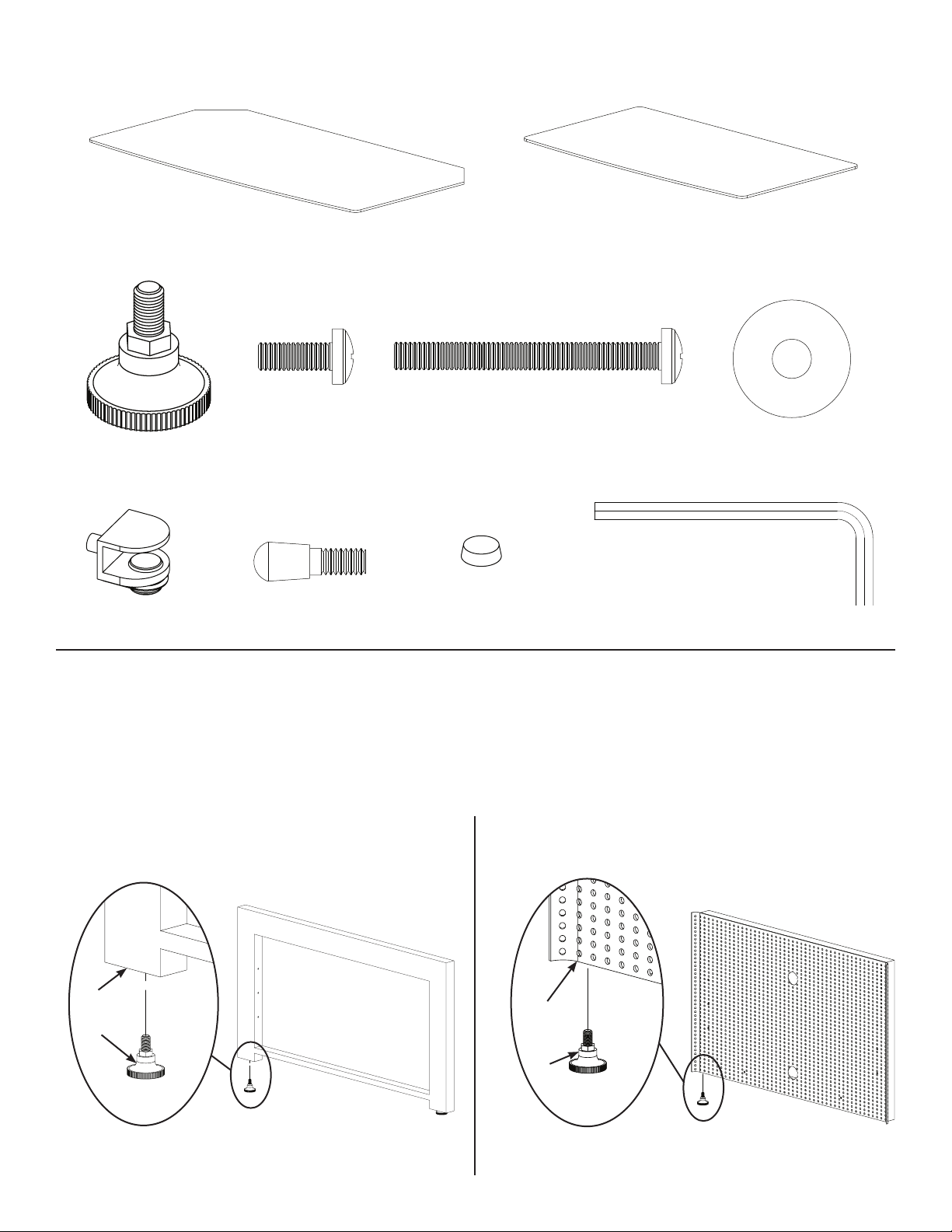
Supplied Parts and Hardware Continued: (Threaded fasteners are shown actual size.)
Foot - G
Qty. 4
Shelf Clamp - K
Qty. 2
Top Glass Shelf - E
Qty. 1
M6 x 16 MM Bolt - H
Qty. 6
Shelf Pin - L
Qty. 2
M6 x 60 MM Bolt - I
Qty. 3
Glass Protector - M
Qty. 8
Glass Shelf - F
Qty. 2
M6 Washer - J
Qty. 3
Allen Key - N
Qty. 1
Step 1: Install Feet
NOTE: If necessary, the Feet (G) can be used to level the SFV41 after it is fully assembled.
Fully thread two Feet (G) into the bottom of the Front Frame (A) as shown in Diagram 1A.
Fully thread two Feet (G) into the bottom of the Back Frame (B) as shown in Diagram 1B.
Diagram 1A Diagram 1B
A
G
B
G
 Loading...