

Page 1
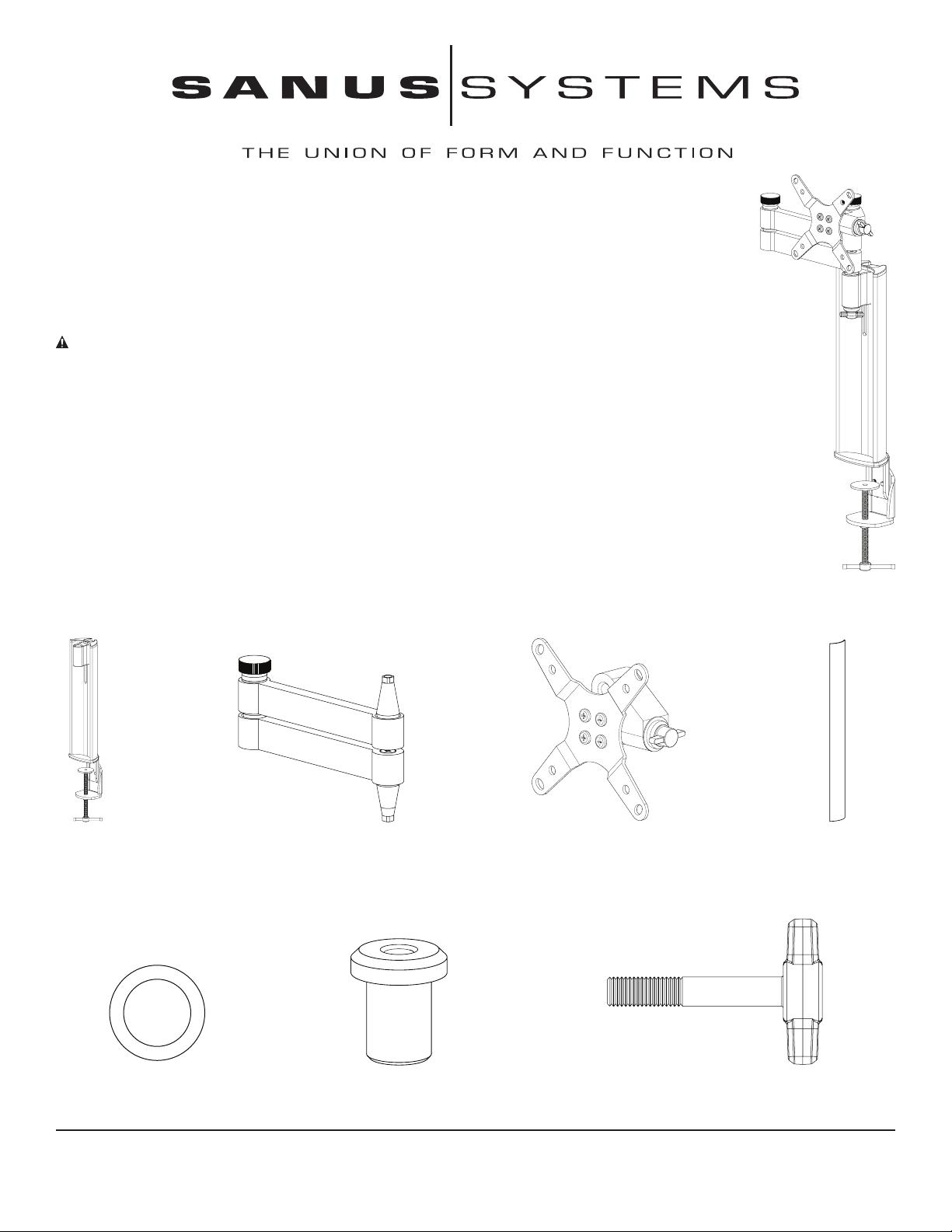
Assembly Instructions for Model: SD115
Thank you for choosing a Sanus Systems desk mount. The SD115 is designed to mount LCD
at panels with a VESA (Video Electronics Standards Association) hole pattern of 75 mm x 75 mm
or 100 mm x 100 mm. It allows you to effortlessly tilt and swivel the monitor up to 15° vertically, and
in almost any direction horizontally.
CAUTION: The weight of the monitor must not exceed 20 lbs (9 kg). Improper installation may cause
property damage or personal injury. Do not use this product for any purpose that is not explicitly specied
by Sanus Systems.
If you do not understand these directions, or have any doubts about the safety of the installation, please
contact Sanus at 800.359.5520 or www.sanus.com. Our customer service representatives can quickly
assist you with installation questions, and missing or damaged parts. Replacement parts for products
purchased through authorized dealers will be shipped directly to you. Check carefully to make sure that
there are no missing or defective parts. Sanus Systems can not be liable for damage or injury caused
by incorrect mounting, incorrect assembly, or incorrect use. Please call Sanus Systems before returning
products to the point of purchase.
Supplied Parts and Hardware
NOTE: Threaded fasteners and washers are shown actual size.
Pillar – A
Qty: 1
Washer – E
Qty: 1
Sanus Systems 2221 Hwy 36 West, Saint Paul, MN 55113 09.07.06 (6901-100122)
Customer Service: 800.359.5520. See complementary Sanus products at www.sanus.com
Arm – B
Qty: 1
Extended Cap – F
Qty: 1
Monitor Mount – C
Qty: 1
Cable Cover – D
Qty: 1
T-Knob – G
Qty: 1
Page 2
Supplied Parts and Hardware (continued)
NOTE: Threaded fasteners and washers are shown actual size.
M4 x 10 Screw–H
Qty: 4
Small Cap – L
Qty: 1
M4 x 30 Screw – I
Qty: 4
Small Washer – M
Qty: 2
Spacer – J
Qty: 4
Round Knob – N
Qty: 1
Large Washer – K
Qty: 1
Allen Key – O
Qty: 1
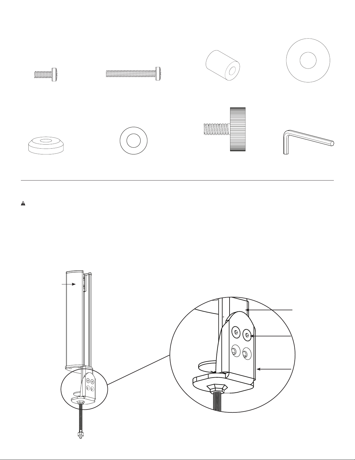
Step 1: Adjust the Pillar Clamp Height for Thicker Desk Surfaces (optional)
CAUTION: Do not adjust the height of the pillar with a monitor attached. Sanus Systems is not responsible for property
damage and/or personal injury.
If you have a thick desk surface, you may need to adjust the pillar clamp height. Loosen and remove the two screws on
the pillar stem (A) with the Allen key (O), as shown in Figure 1. Slide the two pieces of the stem apart until the upper holes
on the outside stem align with the holes on the inner stem. Place the screws through the holes and tighten them with the
Allen key.
Figure 1
Pillar (A)
Inner Stem
Screw
Outer Stem
Page 3
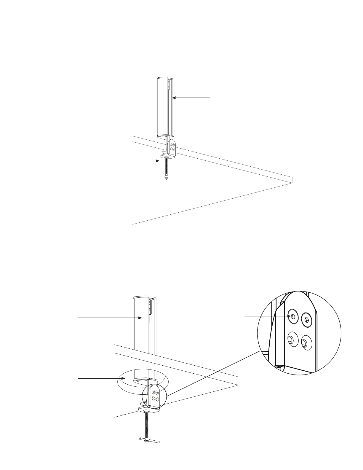
Step 2: Attach the Pillar to the Desk.
To attach the pillar (A) to the edge of the desk as shown in Figure 2a, place the pillar in the desired location. Check that
the pad is resting at on the nished surface of the desk. Secure the pillar (A) by tightening the clamp until the base rests
rmly against the bottom of the desk.
Figure 2a
Pillar (A)
Tighten clamp against
bottom of desk
Desk
To attach the pillar through a wire management hole as shown in Figure 2b, you must rst separate the inner and outer
stems on the pillar. Loosen and remove the two screws on the stem with the Allen key (D), and slide the stems apart.
Place the pillar through the wire management hole, resting the pad at on the nished surface of the desk. Reattach the
outer stem with the two screws and the Allen key. Then secure the pillar by tightening the clamp until the base rests rmly
against the bottom of the desk.
Figure 2b
Pillar (A)
Wire Management
Hole in Desk
Screw on Outer
Stem of Pillar
Page 4

Step 3: Place the Arm into the Pillar
Slide the arm (B) into the pillar (A) by placing the cone-shaped bushing into the opening on the pillar. The knob on the arm
should face up, as shown in Figure 3.
Figure 3
Arm (B)
Pillar (A)
Desk
Step 4: Attach the Arm to the Pillar
Place the washer (E) onto the extended cap (F) and place them onto the bottom cone-shaped bushing on the arm (B), as
shown in Figure 4. Turn the extended cap until it clicks into place, and the square cut ts snugly over the square end of
the arm bushing. Insert the T-knob (G) through a small washer (M) into the extended cap, as shown in Figure 4. Tighten
the T-knob.
CAUTION: Make certain that the arm (B) is rmly attached to the pillar (A). If the arm wobbles, the extended cap (F)
may have slipped off the square end of the arm bushing. Remove the T-knob (G) and turn the extended cap until it clicks
back into place. Then reinsert the T-knob and tighten.
Figure 4
Arm (B)
Pillar (A)
Bushing on
Arm (B)
Pillar (A)
Washer (E)
Extended Cap (F)
Small Washer (M)
T-Knob (G)
Page 5

Step 5: Attach the Monitor Mount to a Monitor with a Flat Back
NOTE: For monitors with curved backs or obstructions, go to Step 6.
Attach the monitor mount (C) to the back of your LCD monitor using the M4 x 10 mm screws (H), as shown in Figure
5. Position the monitor mount so that the large side of the tapered hole faces the bottom of the monitor. Place the four
screws through the monitor mount into the VESA bolt mounting pattern on the back of the monitor. Tighten the screw into
the monitor. Go to Step 7.
Figure 5
M4 x 10 Screw (H)
Tapered hole on Monitor
Mount (C) faces down
M4 x 10 Screw (H)
Step 6: Attach the Monitor Mount to a Monitor with a Curved Back or Obstructions
Attach the monitor mount (C) to the back of your LCD monitor using the M4 x 30 mm screws (I) and the spacers (J), as
shown in Figure 6. Position the monitor mount so that the large side of the tapered hole faces the bottom of the monitor.
Place the four screws through the monitor mount and the spacers, and then into the VESA bolt mounting pattern on the
back of the monitor. Tighten the bolts to the monitor.
Figure 6
Spacer (J)
M4 x 30 Screw (I)
Tapered hole on Monitor
Mount (C) faces down
M4 x 30 Screw (I)
Spacer (J)
Page 6

Step 7: Attach the Monitor Mount and Monitor to the Arm
NOTE: So that all the parts can be seen clearly, this step is shown without the monitor in Figure 7b.
Set the tapered hole in the monitor mount (C) down over the cone-shaped bushing on the arm (B). Make certain the
monitor mount is completely seated onto the arm, as seen in Figures 7a and 7b.
Add the large washer (K). Then add the small cap (L), turning it until the square cut ts over the square top of the coneshaped bushing on the arm. Finally, place the round knob (N) through the small washer (M), the small cap, and the large
washer, and into the cone-shaped bushing on the arm. You can now set the desired level of tension for each of the knobs.
Figure 7a
Monitor Mount (C)
Cone-Shaped Bushing on Arm (B)
Figure 7b
Round Knob (N)
Small Washer (M)
Small Cap (L)
Large Washer (K)
Monitor Mount (C)
Cone-Shaped Bushing
on Arm (B)
Page 7

Step 8: Cable Management
Place the monitor cables into the channel on the back of the pillar (A). Snap the cable cover (D) into the grooves along the
edge of the channel, as shown in Figure 8.
Figure 8
Groove
Cable Cover (D)
Channel on
Pillar (A)
Step 9: Adjust Arm Height (Optional)
Required Tool: Phillips screwdriver
CAUTION: Do not adjust the Arm height if a monitor is attached. Sanus Systems is not responsible for property
damage and/or personal injury.
Remove the Cable Cover (D) from the Pillar (A), and lift the monitor cables out of the channel on the Pillar. See Step
8 for additional information. Remove the Monitor Mount (C) and the attached monitor from the Arm (B). See Step 7 for
additional details about how the Monitor Mount and Arm t together.
Loosen the two screws at the top of the Pillar with a Phillips screwdriver. See Figure 9. Slide the Arm to the desired height,
and tighten the screws with the screwdriver. Replace the Monitor Mount with attached monitor as described in Step 7.
Replace the monitor cables and Cable Cover as described in Step 8.
Figure 9
Bushing on Arm (B)
Screws
CSAV, Inc. and its afliated corporations and subsidiaries (collectively, “CSAV”), intend to make this manual accurate and complete. However, CSAV makes no claim that the information contained herein
covers all details, conditions, or variations. Nor does it provide for every possible contingency in connection with the installation or use of this product. The information contained in this document is subject to
change without notice or obligation of any kind. CSAV makes no representation of warranty, expressed or implied, regarding the information contained herein. CSAV assumes no responsibility for accuracy,
completeness or sufciency of the information contained in this document.
Page 8

SD115 ADDENDUM
This Addendum covers the assembly procedure for the SD115 Monitor Mount.
Supplied Parts and Hardware
Make sure all parts are included and undamaged. Never use defective parts. If hardware is damaged or missing, contact your local
hardware store or Sanus Systems. Before returning products to the point of purchase, contact Sanus Systems. Replacement parts
for products purchased through authorized dealers are shipped directly to you.
[02] x1
[01] x1
Sanus Systems 2221 Hwy 36 West, St Paul, MN 55113 USA • 12.19.06 (6901-100138)
Customer Service 800.359.5520 • www.sanus.com
[03] x1
[06] x1[05] x1[04] x1
Page 9

1
The square surfaces of the shaft on the head [01] and Spacer [04] must nest together.
[02]
[03]
[01]
[04]
[05]
[06]
CSAV, Inc. and its affiliated corporations and subsidiaries (collectively, “CSAV”), intend to make this manual accurate and complete. However, CSAV makes no claim that the information contained herein covers all details,
conditions, or variations. Nor does it provide for every possible contingency in connection with the installation or use of this product. The information contained in this document is subject to change without notice
or obligation of any kind. CSAV makes no representation of warranty, expressed or implied, regarding the information contained herein. CSAV assumes no responsibility for accuracy, completeness or sufficiency of the
information contained in this document.
2
6901-100138
 Loading...