

Page 1
SA206 INSTRUCTION MANUAL
We’ll Make It Stress-Free
If you have any questions along the way, just give us a call.
1-800-359-5520. We’re ready to help!
Scan for more information
about this product
san.us/449
Page 2
2
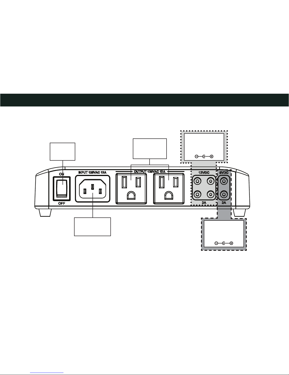
IMPORTANT SAFETY INSTRUCTIONS – SAVE THESE INSTRUCTIONS – PLEASE READ ENTIRE MANUAL PRIOR TO USE
12 VDC
2A Max Total*
5.5mm OD
2.5mm ID
* Maximum DC Output:
12VDC - 2A
5VDC - 2A
Each individual jack can output up to 2A.
Do not exceed maximum ratings.
Master
Power
Switch
IEC Power
Inlet
12A/125V/60HZ
Power Outlet
125 VAC
60 Hz
12A
Power Outlets
5 VDC
2A Max Total*
5.5mm OD
2.1mm ID
Page 3

3
CAUTION: Avoid potential personal injuries and property damage!
ƕ To Reduce the Risk of Electric Shock - Use Only in Dry Locations Indoors!
ƕ The input plug of this power tap is intended to serve as the disconnect device, it shall be easily accessible and withdrawn.
ƕ This power center does not contain internal circuit breaker protection. INSTALLER MUST ensure that the input of this power center
is connected individually to an electrical service panel that is protected with a UL Listed 20A (Maximum) circuit breaker for overload
protection of the power center.
ƕ Not for use with ground-fault circuit-interrupter receptacles or receptacles with indicatior lights or controls.
ƕ To reduce the risk of fire or electric shock, do not use this device with a receptacle in which the slot openings to not align with the
blades.
ƕ Do not install this device if there is not at least 30 feet (10 meters) or more of wire between the electrical outlet and the electrical service
panel.
ƕ All accessories must be grounded.
ƕ Elevated Operating Ambient - If installed in a closed or multi-unit rack assembly, the operating ambient temperature of the rack
environment may be greater than room ambient. Therefore, consideration should be given to installing the equipment in an environment
compatible with the maximum ambient temperature (32-104°F/30-40°C) specifi ed by the manufacturer.
ƕ Reduced Air Flow - Installation of the equipment in a rack should be such that the amount of air fl ow required for safe operation of the
equipment is not compromised.
ƕ Circuit Overloading - Consideration should be given to the connection of the equipment to the supply circuit and the e ect that
overloading of the circuits might have on overcurrent protection and supply wiring. Appropriate consideration of equipment nameplate
ratings should be used when addressing this concern.
ƕ Do not use this product for any purpose not explicitly specified by manufacturer.
ƕ If you do not understand these instructions, or have doubts about the safety of the installation, assembly or use of this product, contact
Customer Service or call a qualified contractor.
ƕ Manufacturer is not responsible for damage or injury caused by incorrect assembly or use.
Page 4
4
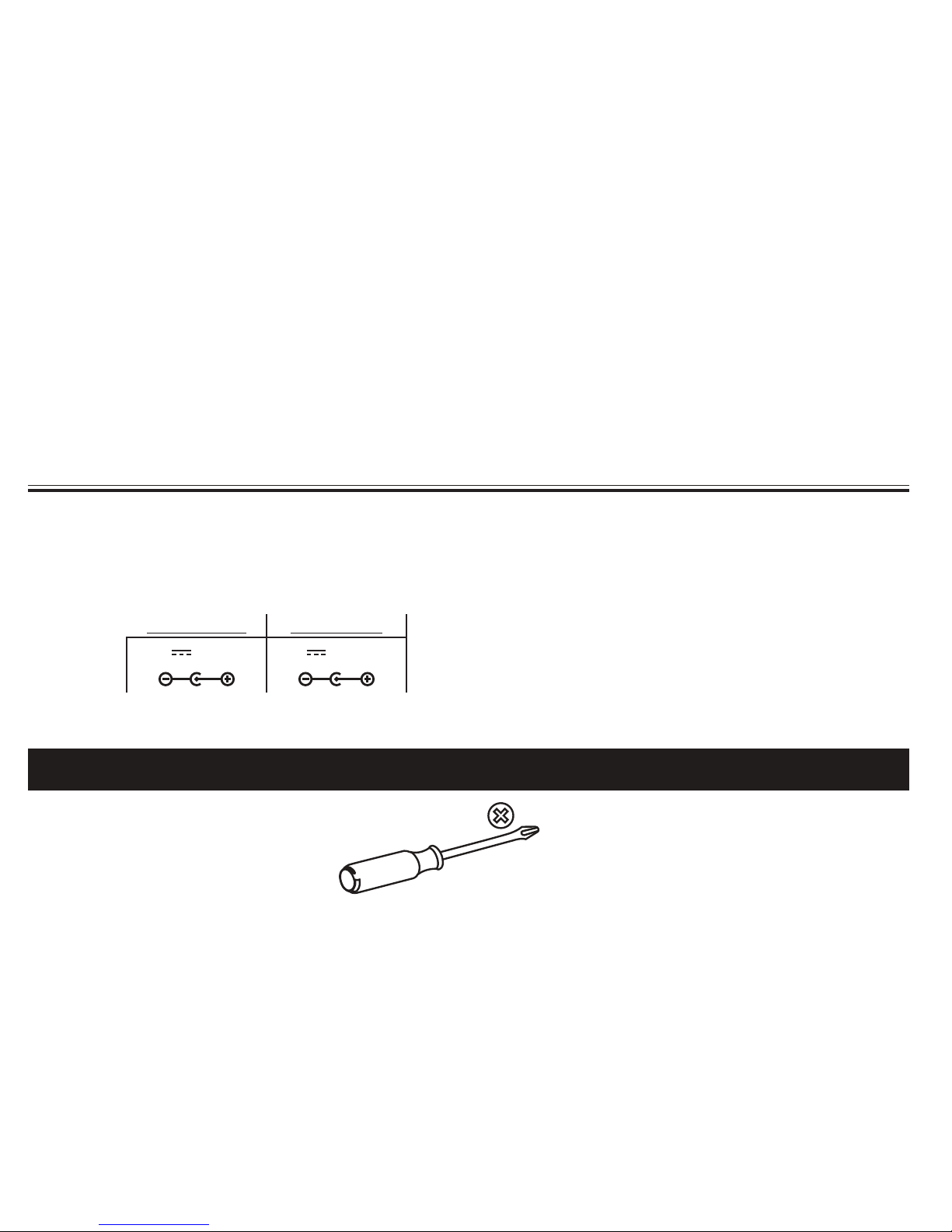
Recommended Tools
WARRANTY
The SA206 SANUS ECO-Mini™ Multi-volt Power Supply is covered by a five year product warranty against manufacturer’s defects. If you
have any questions or experience any problems with your Sanus product, please contact Sanus Customer Service.
Specifications
ƕ Power Input Connection: IEC 320 C14 (Use power supply cord with NEMA 5-15P plug type only.)
ƕ 1500 joule
ƕ EMI/RFI noise filtration
ƕ 12A/125V/60Hz
ƕ Suppressed voltage rating: L-N 400V
ƕ Outputs:
12 VDC 2A Max 5 VDC 2A Max
12V
2A Max* 5V 2A Max*
* Maximum DC Output:
12VDC - 2A
5VDC - 2A
Each individual jack can output up to 2A.
Do not exceed maximum ratings.
Page 5
5
5V DC
2A Max
12V DC
2A Max
3.5 mm OD
1.35 mm ID
5.5 mm OD
2.1 mm ID
5.5 mm OD
2.1 mm ID
5.5 mm OD
2.5 mm ID
5.5 mm OD
2.5 mm ID
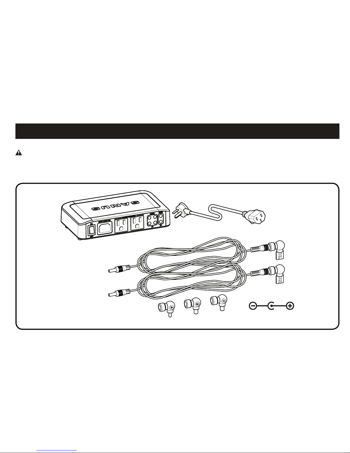
WARNING: This product contains small items that could be a choking hazard if swallowed.
Before starting assembly, verify all parts are included and undamaged. If any parts are missing or damaged, do not return the damaged item
to your dealer; contact Customer Service. Never use damaged parts!
Supplied Parts
ECO-Mini with Power Cord
ECO-Mini DC Cable Kit with Adapters
Page 6
6
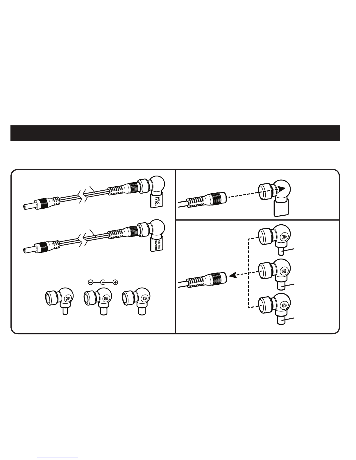
ECO-Mini DC Cable Kit
3.5 mm OD
1.35 mm ID
5.5 mm OD
2.1 mm ID
5.5 mm OD
2.5 mm ID
Remove cover of the
appropriate cord.
Replace cover with the
required Component
Adapter.
12V DC
2A Max
5V DC
2A Max
12V DC
2A Max
Black/Black
Black/Red
3.5 mm OD
1.35 mm ID
5.5 mm OD
2.1 mm ID
5.5 mm OD
2.5 mm ID
When using DC power, test the cables and component adapters first.
1. Does your component use 5V DC or 12V DC?
2. Does one of the three Component Adapters fit your component?
Component Adapters
Page 7

7
1
Using ECO-Mini with SA808/SA809 (purchased separately) - Optional
1. To use the ECO-Mini in the SA808 or SA809 in-wall boxes
(purchased separately), first remove feet.
2. Fit the ECO-Mini into the ECO-Mini bracket supplied with the
SA808 and SA809 (purchased separately).
3. Use two of the screws from the feet to secure the ECO-Mini in
the bracket.
2
3
Page 8

8
Using ECO-Mini with SA808 and SA809 - Optional cont.
4. Slide the ECO-Mini and bracket into the top of the housing of the SA808 or SA809. Lock the bracket into the housing by sliding it towards
the corner until you feel it catch.
4 SA808 4 SA809
Page 9

9
Using ECO-Mini with SA808 and SA809 - Optional cont.
5. Use the ECO-Mini power cord to supply power to the ECO-Mini.
5
Page 10

10
Using ECO-Mini on a Wall - Optional Using ECO-Mini on a Shelf - Optional
To wall mount the ECO-Mini, fi rst remove feet. Then hang the ECOMini using the keyhole slots on the bottom from nails or screws (not
included) inserted in the wall. Nails or screws should be level and
spaced 6.3 inches (160 mm) apart.
The ECO-Mini can also be placed on a shelf or inside a rack. Do not
remove feet.
Page 11

11
Dimensions Troubleshooting
7.68 in.
[195 mm]
6.3 in.
[160 mm]
1.50 in.
[38.1 mm]
4.33 in.
[110 mm]
1.76 in.
[44.76 mm]
If you have no output power
1. Make sure the unit is plugged into a functioning outlet.
2. Make sure the power switch is in the on position.
3. Turn the unit off for 30 seconds, turn it back on.
If it works, you are done.
If it does not, please call Customer Service.
Page 12

12
ESPAÑOL
INSTRUCCIONES DE SEGURIDAD IMPORTANTES. CONSÉRVELAS. LEA TODO EL MANUAL ANTES DE UTILIZAR ESTE PRODUCTO.
PRECAUCIÓN: Evite lesiones y daños materiales.
ƕ Para reducir el riesgo de descarga eléctrica, utilice este producto únicamente en lugares techados y secos.
ƕ El enchufe de este tomacorriente múltiple constituye su mecanismo de desconexión, por lo que deberá ubicarse en un lugar al
que pueda accederse fácilmente para retirarlo.
ƕ Este centro de alimentación no cuenta con disyuntor interno. El INSTALADOR DEBE cerciorarse de que el enchufe de este centro
de alimentación se conecte individualmente a un tablero eléctrico protegido por un disyuntor de 20 A (como máximo) aceptado
por UL, a fin de que el centro esté protegido contra sobrecargas.
ƕ No se debe usar con tomacorrientes con interruptor de circuito por fallos de conexión a tierra.
ƕ Para reducir el riesgo de incendios y descargas eléctricas, no utilice este dispositivo con un tomacorriente en el que las ranuras
no se alineen con los bornes.
ƕ No instale este dispositivo si no hay al menos 10 metros (30 pies) o más de cable entre el tomacorriente y el tablero eléctrico.
ƕ Todos los accesorios deben estar conectados a tierra.
ƕ Temperatura de funcionamiento elevada – Si se instala el producto en un bastidor cerrado o con múltiples unidades, la temperatura
de funcionamiento puede resultar superior a la temperatura de la habitación. Por lo tanto, considere instalar el equipo en una
habitación compatible con la temperatura ambiente máxima (0 °C a 40 °C/32 °F a 104 °F) que especifica el fabricante.
ƕ Flujo de aire reducido – La instalación del equipo en un bastidor debe realizarse respetando el volumen de flujo de aire requerido
para el manejo seguro del equipo.
ƕ Sobrecarga del circuito – La conexión del equipo al circuito de alimentación debe realizarse teniendo en consideración el efecto
que podría ocasionar la sobrecarga de los circuitos sobre la protección contra sobretensión y el cableado eléctrico. Por lo tanto,
deben tenerse en cuenta los valores indicados en la placa de identificación del equipo.
ƕ No utilice este producto para ningún otro propósito que no sea el especificado explícitamente por el fabricante.
ƕ Si no entiende las instrucciones o si tiene dudas acerca de la seguridad de la instalación, del ensamblado o del uso del producto,
póngase en contacto con el servicio de atención al cliente o llame a un técnico calificado.
ƕ El fabricante no se responsabiliza por ningún daño o lesión resultante del montaje incorrecto o de uso indebido.
Page 13

13
ESPAÑOL
Herramientas recomendadas Ver página 3
Piezas suministradas Ver página 3
ADVERTENCIA: Este producto contiene piezas pequeñas que, si fuesen tragadas, podrían producir asfixia.
Antes de iniciar el ensamblaje, compruebe que todas las piezas estén incluidas y en buenas condiciones. Si faltan piezas o alguna está
dañada, no devuelva el artículo al distribuidor; póngase en contacto con el servicio de atención al cliente. Nunca utilice piezas deterioradas.
Kit de cables de CC ECO-Mini
Antes de usar energía de CC, pruebe los cables y adaptadores de los componentes.
1. ¿Su componente usa 5V o 12V de CC?
2. ¿Alguno de los tres Adaptadores de componentes coincide con su componente?
Retire la cubierta del cable apropiado.
Vuelva a colocar la cubierta con el Adaptador del componente que se requiera.
GARANTÍA
La fuente de alimentación multivoltaje SANUS ECO-Mini™ SA206 tiene una garantía de cinco años contra defectos de fabricación. Si tiene
alguna pregunta o inconveniente con este producto, póngase en contacto con el servicio de atención al cliente de Sanus.
Especificaciones
ƕ Conector de alimentación: IEC 320 C14 (Utilice un cable de alimentación con el único tipo NEMA 5-15P.)
ƕ 1500 julios
ƕ Filtración de ruido EMI/RFI
ƕ 12A/125V/60Hz
ƕ Capacidad de protección contra sobretensión: L-N 400 V
ƕ Salidas:
12 VDC 2A Máx. 5 VDC 2A Máx.
12V
2A Máx*.
(por conector)
5V 2 A Máx*.
(por conector)
*Salida DC máxima:
12VDC - 2A
5VDC - 2A
Cada gato individuo puede producir hasta 2A.
No exceda valores máximos.
Page 14

14
ESPAÑOL
Uso del ECO-Mini con SA808/SA809 (se vende por separado) - Opcional
1. Para usar ECO-Mini en cajas empotradas SA808 o SA809 (se vende por separado), primero debe retirar la base.
2. Coloque ECO-Mini en la placa de sujeción del ECO-Mini incluida con SA808 y SA809 (se vende por separado).
3. Use 2 de los tornillos de la base para asegurar el ECO-Mini en la placa de sujeción.
4. Deslice el ECO-Mini y la placa de sujeción hacia la parte superior de la carcasa de SA808 o SA809. Bloquee la placa de sujeción en la
carcasa. Para ello, deslícela hacia la esquina hasta que se enganche.
5. Use el cable de alimentación ECO-Mini para suministrarle electricidad al ECO-Mini.
Uso del ECO-Mini sobre una pared - Opcional
Para montar el ECO-Mini en la pared, primero retire la base. Luego cuelgue el ECO-Mini usando las ranuras de la parte inferior con clavos o
tornillos (no se incluyen) insertados en la pared. Los clavos o tornillos se deben nivelar y colocar a una distancia de 160 mm (6.3") uno de otro.
Uso del ECO-Mini sobre una repisa - Opcional
También puede colocar el ECO-Mini en una repisa o dentro de un bastidor. No retire la base.
Dimensiones
Resolución de problemas
Si no tiene potencia de salida
1. Asegúrese de que la unidad esté conectada a un tomacorriente que funcione.
2. Asegúrese de que la llave de encendido esté en la posición de encendido.
3. Apague la unidad por 30 segundos y vuelva a encenderla.
Si funciona, habrá finalizado.
En caso contrario, llame al servicio de atención al cliente.
Page 15

15
ESPAÑOL
Page 16

16
Milestone AV Technologies and its a liated corporations and subsidiaries (collectively, “Milestone”), intend to make this manual accurate and complete. However,
Milestone makes no claim that the information contained herein covers all details, conditions, or variations. Nor does it provide for every possible contingency in
connection with the installation or use of this product. The information contained in this document is subject to change without notice or obligation of any kind.
Milestone makes no representation of warranty, expressed or implied, regarding the information contained herein. Milestone assumes no responsibility for accuracy,
completeness or su ciency of the information contained in this document.
©2013 Milestone AV Technologies, a Duchossois Group Company. All rights reserved. Sanus is a division of Milestone.
All other brand names or marks are used for identifi cation purposes and are trademarks of their respective owners.
Thank you for choosing Sanus! Please take a moment to let us know how we did:
SANUS • 6436 City West Parkway • Eden Prairie, MN 55344 USA 6901-002289 00
Americas: 800-359-5520 • info@sanus.com • Leave a review: sanus.com
UK: 0800-056-2853
Page 17

Page 18

 Loading...